EP4498114A1 - Nls using a bounded linear initial search space and a fixed grid with pre-calculated variables - Google Patents
Nls using a bounded linear initial search space and a fixed grid with pre-calculated variables Download PDFInfo
- Publication number
- EP4498114A1 EP4498114A1 EP23194702.9A EP23194702A EP4498114A1 EP 4498114 A1 EP4498114 A1 EP 4498114A1 EP 23194702 A EP23194702 A EP 23194702A EP 4498114 A1 EP4498114 A1 EP 4498114A1
- Authority
- EP
- European Patent Office
- Prior art keywords
- height
- sensor
- elevation angle
- range
- elevation
- Prior art date
- Legal status (The legal status is an assumption and is not a legal conclusion. Google has not performed a legal analysis and makes no representation as to the accuracy of the status listed.)
- Pending
Links
Images




Classifications
-
- B—PERFORMING OPERATIONS; TRANSPORTING
- B60—VEHICLES IN GENERAL
- B60W—CONJOINT CONTROL OF VEHICLE SUB-UNITS OF DIFFERENT TYPE OR DIFFERENT FUNCTION; CONTROL SYSTEMS SPECIALLY ADAPTED FOR HYBRID VEHICLES; ROAD VEHICLE DRIVE CONTROL SYSTEMS FOR PURPOSES NOT RELATED TO THE CONTROL OF A PARTICULAR SUB-UNIT
- B60W40/00—Estimation or calculation of non-directly measurable driving parameters for road vehicle drive control systems not related to the control of a particular sub unit, e.g. by using mathematical models
- B60W40/02—Estimation or calculation of non-directly measurable driving parameters for road vehicle drive control systems not related to the control of a particular sub unit, e.g. by using mathematical models related to ambient conditions
-
- G—PHYSICS
- G01—MEASURING; TESTING
- G01S—RADIO DIRECTION-FINDING; RADIO NAVIGATION; DETERMINING DISTANCE OR VELOCITY BY USE OF RADIO WAVES; LOCATING OR PRESENCE-DETECTING BY USE OF THE REFLECTION OR RERADIATION OF RADIO WAVES; ANALOGOUS ARRANGEMENTS USING OTHER WAVES
- G01S7/00—Details of systems according to groups G01S13/00, G01S15/00, G01S17/00
- G01S7/02—Details of systems according to groups G01S13/00, G01S15/00, G01S17/00 of systems according to group G01S13/00
- G01S7/40—Means for monitoring or calibrating
-
- G—PHYSICS
- G06—COMPUTING OR CALCULATING; COUNTING
- G06F—ELECTRIC DIGITAL DATA PROCESSING
- G06F17/00—Digital computing or data processing equipment or methods, specially adapted for specific functions
- G06F17/10—Complex mathematical operations
- G06F17/15—Correlation function computation including computation of convolution operations
-
- B—PERFORMING OPERATIONS; TRANSPORTING
- B60—VEHICLES IN GENERAL
- B60W—CONJOINT CONTROL OF VEHICLE SUB-UNITS OF DIFFERENT TYPE OR DIFFERENT FUNCTION; CONTROL SYSTEMS SPECIALLY ADAPTED FOR HYBRID VEHICLES; ROAD VEHICLE DRIVE CONTROL SYSTEMS FOR PURPOSES NOT RELATED TO THE CONTROL OF A PARTICULAR SUB-UNIT
- B60W60/00—Drive control systems specially adapted for autonomous road vehicles
- B60W60/001—Planning or execution of driving tasks
-
- G—PHYSICS
- G01—MEASURING; TESTING
- G01S—RADIO DIRECTION-FINDING; RADIO NAVIGATION; DETERMINING DISTANCE OR VELOCITY BY USE OF RADIO WAVES; LOCATING OR PRESENCE-DETECTING BY USE OF THE REFLECTION OR RERADIATION OF RADIO WAVES; ANALOGOUS ARRANGEMENTS USING OTHER WAVES
- G01S13/00—Systems using the reflection or reradiation of radio waves, e.g. radar systems; Analogous systems using reflection or reradiation of waves whose nature or wavelength is irrelevant or unspecified
- G01S13/02—Systems using reflection of radio waves, e.g. primary radar systems; Analogous systems
- G01S13/06—Systems determining position data of a target
- G01S13/42—Simultaneous measurement of distance and other co-ordinates
-
- G—PHYSICS
- G01—MEASURING; TESTING
- G01S—RADIO DIRECTION-FINDING; RADIO NAVIGATION; DETERMINING DISTANCE OR VELOCITY BY USE OF RADIO WAVES; LOCATING OR PRESENCE-DETECTING BY USE OF THE REFLECTION OR RERADIATION OF RADIO WAVES; ANALOGOUS ARRANGEMENTS USING OTHER WAVES
- G01S13/00—Systems using the reflection or reradiation of radio waves, e.g. radar systems; Analogous systems using reflection or reradiation of waves whose nature or wavelength is irrelevant or unspecified
- G01S13/02—Systems using reflection of radio waves, e.g. primary radar systems; Analogous systems
- G01S13/06—Systems determining position data of a target
- G01S13/46—Indirect determination of position data
-
- G—PHYSICS
- G01—MEASURING; TESTING
- G01S—RADIO DIRECTION-FINDING; RADIO NAVIGATION; DETERMINING DISTANCE OR VELOCITY BY USE OF RADIO WAVES; LOCATING OR PRESENCE-DETECTING BY USE OF THE REFLECTION OR RERADIATION OF RADIO WAVES; ANALOGOUS ARRANGEMENTS USING OTHER WAVES
- G01S13/00—Systems using the reflection or reradiation of radio waves, e.g. radar systems; Analogous systems using reflection or reradiation of waves whose nature or wavelength is irrelevant or unspecified
- G01S13/88—Radar or analogous systems specially adapted for specific applications
- G01S13/93—Radar or analogous systems specially adapted for specific applications for anti-collision purposes
- G01S13/931—Radar or analogous systems specially adapted for specific applications for anti-collision purposes of land vehicles
-
- G—PHYSICS
- G01—MEASURING; TESTING
- G01S—RADIO DIRECTION-FINDING; RADIO NAVIGATION; DETERMINING DISTANCE OR VELOCITY BY USE OF RADIO WAVES; LOCATING OR PRESENCE-DETECTING BY USE OF THE REFLECTION OR RERADIATION OF RADIO WAVES; ANALOGOUS ARRANGEMENTS USING OTHER WAVES
- G01S7/00—Details of systems according to groups G01S13/00, G01S15/00, G01S17/00
- G01S7/02—Details of systems according to groups G01S13/00, G01S15/00, G01S17/00 of systems according to group G01S13/00
- G01S7/40—Means for monitoring or calibrating
- G01S7/4004—Means for monitoring or calibrating of parts of a radar system
- G01S7/4026—Antenna boresight
- G01S7/4034—Antenna boresight in elevation, i.e. in the vertical plane
-
- G—PHYSICS
- G06—COMPUTING OR CALCULATING; COUNTING
- G06F—ELECTRIC DIGITAL DATA PROCESSING
- G06F17/00—Digital computing or data processing equipment or methods, specially adapted for specific functions
- G06F17/10—Complex mathematical operations
- G06F17/16—Matrix or vector computation, e.g. matrix-matrix or matrix-vector multiplication, matrix factorization
-
- G—PHYSICS
- G06—COMPUTING OR CALCULATING; COUNTING
- G06F—ELECTRIC DIGITAL DATA PROCESSING
- G06F18/00—Pattern recognition
- G06F18/20—Analysing
- G06F18/24—Classification techniques
- G06F18/245—Classification techniques relating to the decision surface
- G06F18/2453—Classification techniques relating to the decision surface non-linear, e.g. polynomial classifier
-
- B—PERFORMING OPERATIONS; TRANSPORTING
- B60—VEHICLES IN GENERAL
- B60W—CONJOINT CONTROL OF VEHICLE SUB-UNITS OF DIFFERENT TYPE OR DIFFERENT FUNCTION; CONTROL SYSTEMS SPECIALLY ADAPTED FOR HYBRID VEHICLES; ROAD VEHICLE DRIVE CONTROL SYSTEMS FOR PURPOSES NOT RELATED TO THE CONTROL OF A PARTICULAR SUB-UNIT
- B60W2420/00—Indexing codes relating to the type of sensors based on the principle of their operation
- B60W2420/40—Photo, light or radio wave sensitive means, e.g. infrared sensors
- B60W2420/408—Radar; Laser, e.g. lidar
-
- G—PHYSICS
- G01—MEASURING; TESTING
- G01S—RADIO DIRECTION-FINDING; RADIO NAVIGATION; DETERMINING DISTANCE OR VELOCITY BY USE OF RADIO WAVES; LOCATING OR PRESENCE-DETECTING BY USE OF THE REFLECTION OR RERADIATION OF RADIO WAVES; ANALOGOUS ARRANGEMENTS USING OTHER WAVES
- G01S13/00—Systems using the reflection or reradiation of radio waves, e.g. radar systems; Analogous systems using reflection or reradiation of waves whose nature or wavelength is irrelevant or unspecified
- G01S13/02—Systems using reflection of radio waves, e.g. primary radar systems; Analogous systems
- G01S13/06—Systems determining position data of a target
- G01S13/46—Indirect determination of position data
- G01S2013/462—Indirect determination of position data using multipath signals
-
- G—PHYSICS
- G01—MEASURING; TESTING
- G01S—RADIO DIRECTION-FINDING; RADIO NAVIGATION; DETERMINING DISTANCE OR VELOCITY BY USE OF RADIO WAVES; LOCATING OR PRESENCE-DETECTING BY USE OF THE REFLECTION OR RERADIATION OF RADIO WAVES; ANALOGOUS ARRANGEMENTS USING OTHER WAVES
- G01S13/00—Systems using the reflection or reradiation of radio waves, e.g. radar systems; Analogous systems using reflection or reradiation of waves whose nature or wavelength is irrelevant or unspecified
- G01S13/88—Radar or analogous systems specially adapted for specific applications
- G01S13/93—Radar or analogous systems specially adapted for specific applications for anti-collision purposes
- G01S13/931—Radar or analogous systems specially adapted for specific applications for anti-collision purposes of land vehicles
- G01S2013/9327—Sensor installation details
- G01S2013/93271—Sensor installation details in the front of the vehicles
-
- G—PHYSICS
- G01—MEASURING; TESTING
- G01S—RADIO DIRECTION-FINDING; RADIO NAVIGATION; DETERMINING DISTANCE OR VELOCITY BY USE OF RADIO WAVES; LOCATING OR PRESENCE-DETECTING BY USE OF THE REFLECTION OR RERADIATION OF RADIO WAVES; ANALOGOUS ARRANGEMENTS USING OTHER WAVES
- G01S7/00—Details of systems according to groups G01S13/00, G01S15/00, G01S17/00
- G01S7/02—Details of systems according to groups G01S13/00, G01S15/00, G01S17/00 of systems according to group G01S13/00
- G01S7/41—Details of systems according to groups G01S13/00, G01S15/00, G01S17/00 of systems according to group G01S13/00 using analysis of echo signal for target characterisation; Target signature; Target cross-section
- G01S7/411—Identification of targets based on measurements of radar reflectivity
- G01S7/412—Identification of targets based on measurements of radar reflectivity based on a comparison between measured values and known or stored values
Definitions
- NLS non-linear least squares
- the NLS method relies on a good initial guess, which is then refined through iterations to arrive at a final determination.
- Good techniques have been developed for generating the initial guess; however, they are often plagued by large search spaces. Many times they fail to account for physical and environmental constraints which can dramatically reduce the search space.
- the NLS method may be computationally expensive due to the large amount of calculations associated with various matrices. Performing multiple iterations of the NLS method in a crowded environment can tax associated systems and lead to decreased performance.
- This document is directed to methods of and systems for enabling NLS using a bounded linear initial search space and a fixed grid with pre-calculated variables.
- Some aspects described below include a method that includes receiving, via a sensor, a first signal reflected by an object, where the first signal has a first elevation angle relative to a boresight of the sensor.
- the method also includes receiving, via the sensor, a second signal reflected by the object and a ground plane, where the second signal has a second elevation angle relative to the boresight of the sensor.
- the method further includes determining a range to the object based on at least one of the first signal or the second signal and establishing a maximum height corresponding to an estimated maximum height of the object.
- the method also includes establishing a line of second elevation angles as a function of: first elevation angles, a sensor height, and the range, where the first elevation angles are between: a function of: the sensor height and the range and a function of: the sensor height, the range, and the maximum height.
- the method further includes determining an initial elevation angle pair of one of the first elevation angles and one of the second elevation angles using a search algorithm along the line.
- the method also includes refining, using NLS method, the initial elevation angle pair to determine the first elevation angle and the second elevation angle.
- the method further includes calculating a height of the object based on at least one of the first elevation angle or the second elevation angle and the sensor height.
- Other aspects described below include a system that is configured to perform the above method and computer-readable storage media comprising instructions that, when executed, cause at least one processor to perform the above method.
- a method that includes receiving an initial elevation angle pair of an initial first elevation angle and an initial second elevation angle corresponding to respective signals that have been reflected off an object.
- the first elevation angle corresponding to a direct path reflection from the object and the second elevation angle corresponding to a multipath reflection from the object and a ground.
- the method also includes receiving a grid comprising pre-calculated variables for each of a plurality of grid points. The grid points corresponding to respective angle pairs of first elevation angles and second elevation angles.
- the method further includes refining the initial elevation angle pair by, for each iteration of one or more iterations: determining a closest grid point to a current elevation angle pair, where the initial elevation angle pair is the current elevation angle pair for a first iteration and performing an NLS iteration on the closest grid point using the pre-calculated variables for the closest grid point to determine a next angle pair.
- the next angle pair becomes the current elevation angle pair for a next iteration.
- the method also includes, based on the iterations, determining a final elevation angle pair.
- the final elevation angle pair is one of the grid points.
- the method further includes calculating a height of the object based on the final elevation angle pair.
- Other aspects described below include a system that is configured to perform the above method and computer-readable storage media comprising instructions that, when executed, cause at least one processor to perform the above method.
- the NLS method may be used to determine elevation angles of incoming signals. Although it is very powerful, the NLS method relies on a good initial guess. One key factor for determining reliable initial guesses without undue computational burden is a small search space. Otherwise, the search space may be the entire field-of-view of the sensor.
- the vast majority of detections have a direct path reflection and a multipath reflection off the ground.
- there is information about the environment that may be used to bound the first angles to be less than a gap between sensor limits.
- a first part of the invention receives first and second signals with unknown first and second elevation angles, respectively, that have been reflected by an object, with the second signal also having been reflected off a ground.
- a line of second angles is then established as a function of first angles, a sensor height, and a range to the object. The first angles being bound by a function of the sensor height and the range and a function of the sensor height, the range, and the maximum height.
- a search algorithm e.g. greedy search
- the initial elevation angle pair may then be refined (e.g., using NLS iterations but not necessarily using a grid with precalculated variables as described with regard to the second part of the invention) to determine a height of the object.
- a second part of the invention receives an initial elevation angle pair (not necessarily calculated using a bounded linear initial search space as described with regard to the first part of the invention) and refines it by, for one or more iterations: determining a closest grid point to a current elevation angle pair and performing an NLS iteration on the closest grid point using the pre-calculated variables for the closest grid point to determine a next elevation angle pair. When the iterations have converged a height of the object is calculated based on a final elevation angle pair.
- a small search space e.g., a line with extents well within sensor limits
- computational burden on associated systems may be reduced compared to conventional means by requiring less number of, and only linear, operations.
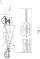
- Fig. 1 illustrates an example environment 100 where NLS using a bounded linear initial search space and a fixed grid with pre-calculated variables may be used.
- the example environment 100 contains a host vehicle 102 with a vehicle system 104 and a portion of a target 106 (hereinafter referred to simply as target 106).
- the host vehicle 102 may be any type of system (automobile, car, truck, motorcycle, e-bike, boat, air vehicle, and so on).
- the target 106 may be a portion of any moving or stationary object.
- the vehicle system 104 transmits a transmission signal (not shown) and receives reflections of the transmission signal that have been reflected by objects (e.g., the target 106). For example, the vehicle system 104 receives a first signal 108 and a second signal 110 that have been reflected off the target 106. The second signal 110 has also been reflected off a ground 112. In other words, the first signal 108 is a direct path reflection while the second signal 110 is a multipath reflection.
- the vehicle system 104 comprises at least one sensor (e.g., radar sensor) that detects the first signal 108 and the second signal 110.
- the sensor has a boresight 114 with a misalignment angle 116 ( ⁇ ). If the boresight 114 is angled toward the ground (as shown), the misalignment angle 116 is negative, while, if the boresight 114 is angled away from the ground, the misalignment angle 116 is positive. If there is no misalignment, the misalignment angle 116 is zero.
- the first signal 108 has a first angle 118 ( ⁇ 1 ) relative to the boresight 114.
- the second signal 110 has a second angle 120 ( ⁇ 2 ) relative to the boresight 114.
- the second angle 120 is necessarily less than zero since it has been reflected off the ground 112 and the first angle 118 is necessarily greater than the second angle.
- the first signal 108 has a first range 122 ( r d ) and the second signal 110 has a second range 124 ( r m ).
- first range and the second range are similar enough to be replaced with a range ( r ) estimated from range-Doppler processing (e.g., they share a similar range value or bin).
- the sensor has a sensor height 126 ( h r ) relative to the ground 112.
- the target 106 has a target height 128 ( h t ) relative to the ground 112.
- the minimum height 130 and the maximum height 132 are discussed further below.
- the vehicle system 104 contains an initial angles module 134, an NLS module 136, and a vehicle component 138.
- the initial angles module 134 is configured to perform a search (e.g., greedy search) along a line 140 of second angles as a function of first angles to determine an initial angle pair 142 ( ⁇ 1 , ⁇ 2 ) .
- the line 140 is bounded based on the minimum height 130 and the maximum height 132. The line 140 and its bounds are discussed further below.
- the NLS module 136 is configured to perform NLS iterations starting with the initial angle pair 142 using an angle grid 144.
- the angle grid 144 has pre-calculated variables for each grid point that are used to simplify (e.g., vectorize) the NLS iterations.
- the NLS module 136 is further configured to calculate the target height 128 based on the final angle pair.
- the target height 128 may then be received by the vehicle component 138 that is configured to perform a vehicle function based on the target height 128.
- the vehicle component 138 may be an advanced driver assist system (ADAS) or autonomous driving function that provides information about the target 106 and/or controls a function of the host vehicle 102 (e.g., speed, trajectory) based on the target height 128.
- ADAS advanced driver assist system
- autonomous driving function that provides information about the target 106 and/or controls a function of the host vehicle 102 (e.g., speed, trajectory) based on the target height 128.
- Fig. 2 illustrates an example of the vehicle system 104.
- Components of the vehicle system 104 may be arranged anywhere within or on the host vehicle 102.
- the vehicle system 104 may include at least one processor 200, computer-readable storage media 202 (e.g., media, medium, mediums), and the vehicle component 138.
- the components are operatively and/or communicatively coupled via a link 204.
- the processor 200 e.g., application processor, microprocessor, digital-signal processor (DSP), controller
- the processor 200 is coupled to the computer-readable storage media 202 via the link 204 and executes instructions (e.g., code) stored within the computer-readable storage media 202 (e.g., non-transitory storage device such as a hard drive, solid-state drive (SSD), flash memory, read-only memory (ROM)) to implement or otherwise cause the initial angles module 134 and the NLS module 136 (or portions thereof) to perform the techniques described herein.
- instructions e.g., code
- non-transitory storage device such as a hard drive, solid-state drive (SSD), flash memory, read-only memory (ROM)
- the initial angles module 134 and the NLS module 136 may be a stand-alone components (e.g., having dedicated computer-readable storage media comprising instructions and/or executed on dedicated hardware, such as a dedicated processor, pre-programmed field-programmable-gate-array (FPGA), system on chip (SOC), and the like).
- the processor 200 and the computer-readable storage media 202 may be any number of components, comprise multiple components distributed throughout the host vehicle 102, located remote to the host vehicle 102, dedicated or shared with other components, modules, or systems of the host vehicle 102, and/or configured differently than illustrated without departing from the scope of this disclosure.
- the computer-readable storage media 202 also contains sensor data 206 generated by one or more sensors or types of sensors (not shown) that may be local or remote to the vehicle system 104.
- the sensor data 206 indicates or otherwise enables the determination of information usable to perform the techniques described herein.
- one or more of the sensors e.g., radar
- the vehicle component 138 contains one or more systems or components that are communicatively coupled to the NLS module 136 and configured to use the target height 128 to perform a vehicle function.
- the vehicle component 138 may comprise a downstream processing module or an Advanced Driver Assist System (ADAS) with means for accelerating, steering, or braking the host vehicle 102.
- ADAS Advanced Driver Assist System
- the vehicle component 138 is communicatively coupled to the NLS module 136 via the link 204.
- the initial angles module 134 and the NLS module 136 may be part of the vehicle component 138 and visa-versa.
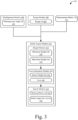
- Fig. 3 illustrates, at 300, an example flow of determining the initial angle pair 142.
- the modules described below may be combined, separated, or rearranged without departing from the scope of this disclosure.
- Aline generation module 302 of the initial angles module 134 receives the misalignment angle 116, a range 304 (r) to the target 106, the minimum height 130, and the maximum height 132 and forms the line 140 using the above variables and the sensor height 126 (which is fixed).
- the misalignment angle 116 may come from a misalignment module 306 and may be determined using any techniques known by those of ordinary skill in the art.
- the range 304 may come from a range module 308 that determines the range 304 to the target 106 based on range-Doppler processing. It is assumed that the first range 122 and the second range 124 are close enough to each other that they register in a similar range bin. Thus, the first range 122 equals the second range 124 equals the range 304.
- the minimum height 130 and the maximum height 132 may come from a height module 310 (e.g., if they are not fixed).
- the minimum height 130 and the maximum height 132 may be functions of the range 304, whether the target 106 is moving or stationary, the range 304 and an azimuth angle of the target 106, and/or whether the target 106 can be identified in a target list.
- the maximum height 132 may be higher for a further target than for a closer one.
- the maximum height may be set to a maximum vehicle height if the target is moving.
- a coordinate of the target 106 and whether it lies on a current road may be determined.
- a maximum height may be smaller for targets on the road than for targets off the road.
- attributes of the first signal 108 and/or the second signal 110 may be compared to attributes or properties of targets in a tracked target list that is maintained by a fusion tracking system (e.g., fusing camera, radar, lidar, etc. data). Responsive to matching one or more of the attributes or properties (e.g., range, range rate, signal-to-noise ratio, azimuth angle), the object data associated with the tracked target in the tracked target list may be used to determine the minimum height 130 and/or the maximum height 132.
- a fusion tracking system e.g., fusing camera, radar, lidar, etc. data.
- the object data associated with the tracked target in the tracked target list may be used to determine the minimum height 130 and/or the maximum height 132.
- the minimum height 130 and/or the maximum height 132 may be set based on typical values for a car.
- ⁇ 2 ⁇ sin ⁇ 1 sin ⁇ 1 + ⁇ + 2 h r r ⁇ ⁇ where the line 140 is bounded by sin ⁇ 1 h l ⁇ h r r ⁇ ⁇ ⁇ ⁇ 1 ⁇ sin ⁇ 1 h v ⁇ h r r ⁇ ⁇ (e.g., based on environmental aspects).
- Equation 1 is a general case. If misalignment and the minimum height are not considered Equation 1 becomes Equation 2.
- ⁇ 2 ⁇ sin ⁇ 1 sin ⁇ 1 + 2 h r r where sin ⁇ 1 ⁇ h r r ⁇ ⁇ 1 ⁇ sin ⁇ 1 h v ⁇ h r r .
- the line 140 is received by a search module 312 of the initial angles module 134 that performs a search along the line 140 to determine the initial angle pair 142.
- the search module 312 may utilize a steering matrix 314 ( A ) and a measurement matrix 316 ( Y ) (e.g., received from the sensor) and solves Equation 3 using the search algorithm (e.g., a greedy search).
- Equation 3 The solution to Equation 3 is the initial angle pair 142. Because the line 140 is bounded by functions based on the minimum height 130 and the maximum height 132, the search space is considerably reduced compared with traditional techniques. Not only does that cause less likelihood of the search algorithm getting trapped by local minima, but it also makes determining the initial angle pair 142 quicker and less computationally burdensome.
- Fig. 4 illustrates, at 400, the line 140.
- the line 140 is based on Equation 1.
- physics aspects dictate that the second angle 120 is a function of the first angle 118, the misalignment angle 116, the sensor height 126, and the range 304 (e.g., ⁇ sin ⁇ 1 sin ⁇ 1 + ⁇ + 2 h r r ⁇ ⁇ ).
- Environmental aspects dictate that the first angle 118 is greater than a function of the minimum height 130, the sensor height 126, the range 304, and the misalignment angle 116 (e.g., sin ⁇ 1 h l ⁇ h r r ⁇ ).
- the first angle 118 is less than a function of the maximum height 132, the sensor height 126, the range 304, and the misalignment angle 116 (e.g., sin ⁇ 1 h v ⁇ h r r ⁇ ⁇ ). Accordingly, the search space accounts for misalignment while being shrunk considerably from sensor fields-of-view, especially at long ranges.
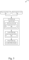
- Fig. 5 illustrates, at 500, an example flow of determining the target height 128.
- the modules described below may be combined, separated, or rearranged without departing from the scope of this disclosure.
- An update module 502 of the NLS module 136 receives the measurement matrix 316, the initial angle pair 142, and the angle grid 144 and determines a final angle pair 504 using NLS iterations. It should be noted that the initial angle pair 142 is not necessarily determined using the previous techniques. Any known techniques of determining/finding an initial angle pair may be used without departing from the scope of this disclosure.
- the angle grid 144 contains a plurality of grid points 506 with respective variables 508 ( B, C, F, A ⁇ ).
- the grid points 506 may be pre-defined pairs of angles within a field of view of the sensor (e.g., possible pairs of the first angle 118 and the second angle 120) or may be placed based on some prior information (e.g., sensor height 126, minimum height 130, maximum height 132, range 304).
- Each of the grid points 506 contains a set of variables 508 that have been calculated for that grid point.
- the variables 508 are defined according to Equations 4.
- variables 508 may be pre-calculated and stored in the angle grid 144 and some of the variables 508 may be calculated in real-time.
- F BB H .
- variable B may be stored in the angle grid 144 and variable F may be calculated in real-time.
- any number of variables 508 may be stored for each grid point 506.
- the update module 502 performs NLS iterations starting with the initial angle pair 142 and using the variables 508. To do so, the update module 502 determines a closest grid point 506 to a current angle pair (e.g., the initial angle pair 142 for the first iteration), receives the variables 508 associated with the grid point 506, and calculates a Hessian matrix ( H ) and a gradient vector ( g ) according to Equations 5 and 6, respectively.
- the operations of calculating the Hessian matrix and the gradient vector for each iteration are all linear (e.g., it is vectorized). This makes the computation of the Hessian matrix and the gradient vector much more simplified compared to traditional means. Accordingly, computational resources may be preserved.
- the update module 502 uses the Hessian matrix, the gradient vector, and the current angle pair (e.g., the initial angle pair 142 for the first iteration), the update module 502 then determines the next angle pair according to either a line search (according to Equation 7) or a trust region function (according to Equation 8) and the process repeats until convergence.
- ⁇ ( l ) is the current angle pair
- ⁇ H -1 g and (H + ⁇ ⁇ diag( H )) -1 g correspond to offsets or distances to the next angle pair
- ⁇ is a damping factor that is a non-negative scalar and determines a size of the trust region (also known as Levenberg-Marquardt algorithm).
- the most-recent grid point 506 becomes the final angle pair 504. Any number of ways may be used to determine convergence. For example, if the next angle pair is closest to the current angle pair, convergence may be assumed. (e.g., the closest grid point is the previous closest grid point).
- the final angle pair 504 is then received by a height module 510 that calculates the target height 128 based on the final angle pair 504.
- the height module 510 may use one of Equations 9 or 10 to calculate the target height 128.
- Fig. 6 illustrates, at 600, an example of NLS iterations using the angle grid 144 with the variables 508.
- the iterations start with the initial angle pair 142.
- a grid point 506 that is closest to the initial angle pair 142 is determined (e.g., 506-1) and the variables 508 for grid point 506-1 are used to calculate the Hessian matrix and the gradient vector.
- the Hessian matrix and the gradient vector are then used to determine a next angle pair from the initial angle pair 142 (e.g., angle pair 602-1).
- the process determines a closest grid point 506 to the angle pair 602-1 (e.g., 506-2).
- the variables 508 for the grid point 506-2 are used to calculate the Hessian matrix and the gradient vector.
- the Hessian matrix and the gradient vector are then used to determine the next angle pair from the current angle pair (e.g., angle pair 602-2).
- the process determines a closest grid point 506 to the angle pair 602-2 (e.g., 506-3).
- the process determines the next angle pair from the previous angle pair by calculating the Hessian matrix and the gradient vector using the variables for grid point 506-3.
- the next angle pair is 602-3.
- the process may determine that convergence has occurred. Accordingly, grid point 506-3 becomes the final angle pair 504. Other techniques may be used to determine convergence without departing from the scope of this disclosure. In some implementations, the angle pair 602-3 may be considered the final angle pair 504.
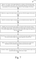
- Fig. 7 is an example method 700 of NLS using a bounded linear initial search space.
- the example method 700 may be implemented in any of the previously described environments, by any of the previously described systems or components, and by utilizing any of the previously described data flows, process flows, or techniques.
- the order in which the operations are shown and/or described is not intended to be construed as a limitation, and the order may be rearranged without departing from the scope of this disclosure.
- any number of the operations can be combined with any other number of the operations to implement the example process flow or an alternate process flow.
- a first signal reflected by an object is received at a first elevation angle relative to a boresight of a sensor, and a second signal reflected by the object and a ground plane is received at a second elevation angle relative to the boresight of the sensor.
- the initial angles module 134 may receive the measurement matrix 316 corresponding to the first signal 108 and the second signal 110.
- a range to the object is determined based on at least one of the first signal or the second signal.
- the range module 308 may calculate the range 304 through range-Doppler processing of the first signal 108 and/or the second signal 110.
- a maximum height corresponding to an estimated maximum height of the object is established.
- the height module 310 may establish the maximum height 132.
- a line of second elevation angles as a function of first elevation angles, a sensor height, and the range is established.
- the first elevation angles being between a function of the sensor height and the range and a function of the sensor height, the range, and the maximum height.
- the line generation module 302 may establish the line 140 (e.g., according to Equation 2) based on the sensor height 126 and the range 304.
- the first elevation angles may be between a function of the sensor height 126 and the range 304 (e.g., sin ⁇ 1 h l ⁇ h r r ⁇ ⁇ ) and a function of the sensor height 126, the range 304, and the maximum height 132 (e.g., sin ⁇ 1 h v ⁇ h r r ⁇ ⁇ ).
- an initial elevation angle pair of one of the first elevation angles and one of the second elevation angles is determined using a search algorithm along the line.
- the search module 312 may use a greedy search algorithm along the line 140 (e.g., via Equation 3) to determine the initial angle pair 142.
- the initial elevation angle pair is refined using an NLS method to determine the first elevation angle and the second elevation angle.
- the NLS module 136 may apply an NLS method to determine a final elevation angle pair.
- the NLS method may or may not use the angle grid 144 with precalculated variables.
- a traditional NLS method may be applied to determine the final elevation angle pair (e.g., final angle pair 504).
- a height of the object is calculated based on at least one of the first elevation angle or the second elevation angle and the sensor height.
- the height module 510 may calculate the target height 128 using Equation 9 or 10.
- Fig. 8 is an example method 800 of NLS using a fixed grid with pre-calculated variables.
- the example method 800 may be implemented in any of the previously described environments, by any of the previously described systems or components, and by utilizing any of the previously described data flows, process flows, or techniques.
- the order in which the operations are shown and/or described is not intended to be construed as a limitation, and the order may be rearranged without departing from the scope of this disclosure.
- any number of the operations can be combined with any other number of the operations to implement the example process flow or an alternate process flow
- an initial elevation angle pair of an initial first elevation angle and an initial second elevation angle corresponding to respective signals that have been reflected off an object are received.
- the NLS module 136 may receive the initial angle pair 142 corresponding to the first signal 108 and the second signal 110.
- the initial angle pair 142 may be determined via any number of techniques, including those described in regard to Figs. 1 , 3 , 4 , and 7 as well as conventional techniques.
- a grid comprising pre-calculated variables for each of a plurality of grid points is received.
- the grid points correspond to respective angle pairs of first elevation angles and second elevation angles.
- the update module 502 may receive the angle grid 144 which contains the grid points 506 with associated variables 508 (e.g., calculated according to Equations 4).
- the initial elevation angle pair is refined by, for each iteration of one or more iterations: determining a closest grid point to a current elevation angle pair, where the initial elevation angle pair is the current elevation angle pair for a first iteration and performing an NLS iteration on the closest grid point using the pre-calculated variables for the closest grid point to determine a next elevation angle pair.
- the next elevation angle pair becomes the current elevation angle pair for a next iteration.
- the update module 502 may perform NLS iterations (e.g., using Equation 7 or 8) along grid points 506 by using respective variables 508 for the grid points to update the Hessian matrices and gradient vectors (e.g., using Equation 5 and Equation 6) starting with a grid point 506 closest to the initial angle pair 142.
- a final elevation angle pair is determined.
- the final elevation angle pair is one of the grid points.
- the update module 502 may determine the final angle pair 504 by determining that the NLS iterations have achieved convergence.
- the final angle pair 504 being one of the grid points 506.
- a height of the object is calculated based on the final elevation angle pair.
- the height module 510 may calculate the target height 128 using Equation 9 or Equation 10.
- Example 1a A method comprising: receiving, via a sensor and at a first elevation angle relative to a boresight of the sensor, a first signal reflected by an object; receiving, via the sensor and at a second elevation angle relative to the boresight of the sensor, a second signal reflected by the object and a ground plane; determining a range to the object based on at least one of the first signal or the second signal; establishing a maximum height corresponding to an estimated maximum height of the object; establishing a line of second elevation angles as a function of first elevation angles, a sensor height, and the range, wherein the first elevation angles are between a first value based on the sensor height and the range and a second value based on the sensor height, the range, and the maximum height; determining an initial elevation angle pair of one of the first elevation angles and one of the second elevation angles using a search algorithm along the line; refining, using an NLS method, the initial elevation angle pair to determine the first elevation angle and the second elevation angle; and calculating a height of the object
- Example 2a The method of example 1a, further comprising performing a vehicle function based on the height of the object.
- Example 3a The method of example 2a, wherein the vehicle function comprises an advanced driver assist system or autonomous driving function.
- Example 4a The method of example 1a, wherein the function comprises a negative inverse sin of: a sin of the first elevation angle plus a ratio of twice the sensor height and the range.
- Example 5a The method of example 1a, wherein the first value comprises a negative inverse sin of a ratio of the sensor height and the range.
- Example 6a The method of example 1a, wherein the second value comprises an inverse sin of a ratio of a difference between the maximum height and the sensor height and the range.
- Example 7a The method of example 1a, further comprising determining a misalignment angle between the sensor and the ground plane, wherein: the line of second elevation angles is further a function of the misalignment angle, the first value is based further on the misalignment angle, and the second value is based further on the misalignment angle.
- Example 8a The method of example 1a, further comprising establishing a minimum height corresponding to an estimated minimum height of the object, wherein the first value is based further on the minimum height.
- Example 9a The method of example 1a, wherein the search algorithm is a greedy search algorithm.
- Example 10a The method of example 1a, wherein the maximum height is based on the range.
- Example 11a The method of example 10a, wherein the maximum height is further based on an azimuth angle of the object.
- Example 12a The method of example 1a, further comprising receiving a target list of tracked targets, wherein the maximum height is based on the target list.
- Example 13a The method of example 12a, further comprising: comparing properties of at least one of the first signal or the second signal to properties of the tracked targets in the target list; and responsive to determining that the properties of at least one of the first signal or the second signal match the properties of one of the tracked targets, determining the maximum height based on the properties of the one of the tracked targets.
- Example 14a The method of example 13a, wherein: the properties of the one of the tracked targets comprise a height of the one of the tracked targets; and the maximum height is set to the height of the one of the tracked targets.
- Example 15a A system comprising: at least one processor configured to: receive, via a sensor and at a first elevation angle relative to a boresight of the sensor, a first signal reflected by an object; receive, via the sensor and at a second elevation angle relative to the boresight of the sensor, a second signal reflected by the object and a ground plane; determine a range to the object based on at least one of the first signal or the second signal; establish a maximum height corresponding to an estimated maximum height of the object; establish a line of second elevation angles as a function of first elevation angles, a sensor height, and the range, wherein the first elevation angles are between a first value based on the sensor height and the range and a second value based on the sensor height, the range, and the maximum height; determine an initial elevation angle pair of one of the first elevation angles and one of the second elevation angles using a search algorithm along the line; refine, using an NLS method, the initial elevation angle pair to determine the first elevation angle and the second elevation angle; and calculate a height of the object
- Example 16a The system of example 15a, further comprising the sensor, wherein the sensor is a radar sensor.
- Example 17a The system of example 15a, wherein the maximum height is based on the range, an azimuth of the object, or a property in a tracked target list.
- Example 18a The system of example 15a, wherein the processor is further configured to receive or determine a misalignment angle between the sensor and the ground plane, wherein: the line of second elevation angles is further a function of the misalignment angle, the first value is further based on the misalignment angle, and the second value is further based on the misalignment angle.
- Example 19a The system of example 15a, wherein the search algorithm is a greedy search algorithm.
- Example 20a A non-transitory computer-readable storage media comprising instructions that, when executed, cause at least one processor to: receive, via a sensor and at a first elevation angle relative to a boresight of the sensor, a first signal reflected by an object; receive, via the sensor and at a second elevation angle relative to the boresight of the sensor, a second signal reflected by the object and a ground plane; determine a range to the object based on at least one of the first signal or the second signal; establish a maximum height corresponding to an estimated maximum height of the object; establish a line of second elevation angles as a function of first elevation angles, a sensor height, and the range, wherein the first elevation angles are between a first value based on the sensor height and the range and a second value based on the sensor height, the range, and the maximum height; determine an initial elevation angle pair of one of the first elevation angles and one of the second elevation angles using a search algorithm along the line; refine, using an NLS method, the initial elevation angle pair to determine the first elevation angle and
- Example 1b A method comprising: receiving an initial elevation angle pair including an initial first elevation angle and an initial second elevation angle corresponding to respective signals from an object, the initial first elevation angle corresponding to a direct path reflection from the object, the initial second elevation angle corresponding to a multipath reflection from the object and a ground; receiving a grid comprising pre-calculated variables for each of a plurality of grid points, the grid points corresponding to respective angle pairs of possible first and second elevation angles; refining the initial elevation angle pair by: for a first iteration: determining a first closest grid point to the initial elevation angle pair; performing an NLS iteration on the first closest grid point using the pre-calculated variables for the first closest grid point to determine a second elevation angle pair; and determining a second closest grid point to the second elevation angle pair; and for each subsequent iteration of one or more subsequent iterations: performing an NLS iteration on a current grid point using the pre-calculated variables for the current grid point to determine a next elevation angle pair, the current grid point being
- Example 2b The method of example 1b, wherein the NLS iteration uses only linear operations.
- Example 3b The method of example 1b, wherein the NLS iteration comprises calculating a Hessian matrix and a gradient vector using the pre-calculated variables and a measurement matrix corresponding to the respective signals.
- Example 4b The method of example 3b, wherein the NLS iteration further comprises using the Hessian matrix and the gradient vector to determine an offset from the closest grid point.
- Example 5b The method of example 4b, wherein the offset comprises a function of the Hessian matrix, the gradient vector, and a damping factor.
- Example 6b The method of example 5b, wherein the NLS iteration comprises a line search or a trust region function.
- Example 7b The method of example 1b, wherein the pre-calculated variables comprise four variables.
- Example 8b The method of example 7b, wherein the pre-calculated variables comprise: a first variable based on a first derivative of a steering matrix and the steering matrix; a second variable based on the steering matrix; a third variable based on the first derivative of the steering matrix and the steering matrix; a fourth variable based on the steering matrix.
- Example 9b The method of example 1b, wherein one of the pre-calculated variables comprises a pseudoinverse of a steering matrix.
- Example 10b The method of example 1b, wherein one of the pre-calculated variables comprises a product of a conjugate transpose of a first derivative of a steering matrix and a function that projects a measurement matrix onto an orthogonal complement of a column space of the steering matrix.
- Example 11b The method of example 10b, wherein another of the pre-calculated variables comprises a product of the conjugate transpose of the first derivative of the steering matrix, the function, and the first derivative of the steering matrix.
- Example 12b The method of example 1b, wherein one of the pre-calculated variables comprises an inverse of a product of a conjugate transpose of a steering matrix and the steering matrix.
- Example 13b The method of example 1b, wherein the subsequent iterations are performed until the subsequent closest grid point is the current grid point.
- Example 14b The method of example 1b, wherein the respective signals are radar signals.
- Example 15b A system comprising: at least one processor configured to: receive an initial elevation angle pair including an initial first elevation angle and an initial second elevation angle corresponding to respective signals from an object, the initial first elevation angle corresponding to a direct path reflection from the object, the initial second elevation angle corresponding to a multipath reflection from the object and a ground; receive a grid comprising pre-calculated variables for each of a plurality of grid points, the grid points corresponding to respective angle pairs of possible first and second elevation angles; refine the initial elevation angle pair by: for a first iteration: determining a first closest grid point to the initial elevation angle pair; performing an NLS iteration on the first closest grid point using the pre-calculated variables for the first closest grid point to determine a second elevation angle pair; and determining a second closest grid point to the second elevation angle pair; and for each subsequent iteration of one or more subsequent iterations: performing an NLS iteration on a current grid point using the precalculated variables for the current grid point to determine a next elevation angle pair, the
- Example 16b The system of example 15b, wherein the NLS iteration uses only linear operations.
- Example 17b The system of example 15b, wherein the NLS iteration comprises calculating a Hessian matrix and a gradient vector using the pre-calculated variables and a measurement matrix corresponding to the respective signals.
- Example 18b The system of example 15b, wherein the subsequent iterations are performed until the subsequent closest grid point is the current grid point.
- Example 19b The system of example 15b, wherein at least one of: one of the precalculated variables comprises a pseudoinverse of a steering matrix; one of the pre-calculated variables comprises a product of a conjugate transpose of a first derivative of the steering matrix and a function that projects a measurement matrix onto an orthogonal complement of a column space of the steering matrix; one of the pre-calculated variables comprises a product of the conjugate transpose of the first derivative of the steering matrix, the function, and the first derivative of the steering matrix; or one of the pre-calculated variables comprises an inverse of a product of the conjugate transpose of the steering matrix and the steering matrix.
- Example 20b A non-transitory computer-readable storage media comprising instructions that, when executed, cause at least one processor to: receive an initial elevation angle pair including an initial first elevation angle and an initial second elevation angle corresponding to respective signals from an object, the initial first elevation angle corresponding to a direct path reflection from the object, the initial second elevation angle corresponding to a multipath reflection from the object and a ground; receive a grid comprising pre-calculated variables for each of a plurality of grid points, the grid points corresponding to respective angle pairs of possible first and second elevation angles; refine the initial elevation angle pair by: for a first iteration: determining a first closest grid point to the initial elevation angle pair; performing an NLS iteration on the first closest grid point using the pre-calculated variables for the first closest grid point to determine a second elevation angle pair; and determining a second closest grid point to the second elevation angle pair; and for each subsequent iteration of one or more subsequent iterations: performing an NLS iteration on a current grid point using the pre-calculated variables
- "at least one of: a, b, or c” is intended to cover a, b, c, a-b, a-c, b-c, and a-b-c, as well as any combination with multiples of the same element (e.g., a-a, a-a-a, a-a-b, a-a-c, a-b-b, a-c-c, b-b, b-b-b, b-b-c, c-c, and c-c-c or any other ordering of a, b, and c).
Landscapes
- Engineering & Computer Science (AREA)
- Physics & Mathematics (AREA)
- Radar, Positioning & Navigation (AREA)
- Remote Sensing (AREA)
- General Physics & Mathematics (AREA)
- Mathematical Physics (AREA)
- Data Mining & Analysis (AREA)
- Theoretical Computer Science (AREA)
- Computer Networks & Wireless Communication (AREA)
- Computational Mathematics (AREA)
- Mathematical Optimization (AREA)
- Pure & Applied Mathematics (AREA)
- Mathematical Analysis (AREA)
- General Engineering & Computer Science (AREA)
- Automation & Control Theory (AREA)
- Mechanical Engineering (AREA)
- Transportation (AREA)
- Software Systems (AREA)
- Algebra (AREA)
- Computing Systems (AREA)
- Databases & Information Systems (AREA)
- Nonlinear Science (AREA)
- Bioinformatics & Computational Biology (AREA)
- Computer Vision & Pattern Recognition (AREA)
- Evolutionary Biology (AREA)
- Evolutionary Computation (AREA)
- Bioinformatics & Cheminformatics (AREA)
- Human Computer Interaction (AREA)
- Artificial Intelligence (AREA)
- Life Sciences & Earth Sciences (AREA)
- Electromagnetism (AREA)
- Radar Systems Or Details Thereof (AREA)
Abstract
Description
- Determining attributes of incoming signals (e.g., radar signals) without other information can be difficult. The non-linear least squares (NLS) method is often used under the deterministic unknown signal assumption. For example, the NLS method may be used to determine elevation angles of incoming signals.
- Although it is very powerful, the NLS method relies on a good initial guess, which is then refined through iterations to arrive at a final determination. Good techniques have been developed for generating the initial guess; however, they are often plagued by large search spaces. Many times they fail to account for physical and environmental constraints which can dramatically reduce the search space.
- Furthermore, the NLS method may be computationally expensive due to the large amount of calculations associated with various matrices. Performing multiple iterations of the NLS method in a crowded environment can tax associated systems and lead to decreased performance.
- This document is directed to methods of and systems for enabling NLS using a bounded linear initial search space and a fixed grid with pre-calculated variables. Some aspects described below include a method that includes receiving, via a sensor, a first signal reflected by an object, where the first signal has a first elevation angle relative to a boresight of the sensor. The method also includes receiving, via the sensor, a second signal reflected by the object and a ground plane, where the second signal has a second elevation angle relative to the boresight of the sensor. The method further includes determining a range to the object based on at least one of the first signal or the second signal and establishing a maximum height corresponding to an estimated maximum height of the object. The method also includes establishing a line of second elevation angles as a function of: first elevation angles, a sensor height, and the range, where the first elevation angles are between: a function of: the sensor height and the range and a function of: the sensor height, the range, and the maximum height. The method further includes determining an initial elevation angle pair of one of the first elevation angles and one of the second elevation angles using a search algorithm along the line. The method also includes refining, using NLS method, the initial elevation angle pair to determine the first elevation angle and the second elevation angle. The method further includes calculating a height of the object based on at least one of the first elevation angle or the second elevation angle and the sensor height. Other aspects described below include a system that is configured to perform the above method and computer-readable storage media comprising instructions that, when executed, cause at least one processor to perform the above method.
- Other aspects described below include a method that includes receiving an initial elevation angle pair of an initial first elevation angle and an initial second elevation angle corresponding to respective signals that have been reflected off an object. The first elevation angle corresponding to a direct path reflection from the object and the second elevation angle corresponding to a multipath reflection from the object and a ground. The method also includes receiving a grid comprising pre-calculated variables for each of a plurality of grid points. The grid points corresponding to respective angle pairs of first elevation angles and second elevation angles. The method further includes refining the initial elevation angle pair by, for each iteration of one or more iterations: determining a closest grid point to a current elevation angle pair, where the initial elevation angle pair is the current elevation angle pair for a first iteration and performing an NLS iteration on the closest grid point using the pre-calculated variables for the closest grid point to determine a next angle pair. The next angle pair becomes the current elevation angle pair for a next iteration. The method also includes, based on the iterations, determining a final elevation angle pair. The final elevation angle pair is one of the grid points. The method further includes calculating a height of the object based on the final elevation angle pair. Other aspects described below include a system that is configured to perform the above method and computer-readable storage media comprising instructions that, when executed, cause at least one processor to perform the above method.
- This Summary introduces simplified concepts for enabling NLS using a bounded linear initial search space and a fixed grid with pre-calculated variables that are further described in the Detailed Description and Drawings. This Summary is not intended to identify essential features of the claimed subject matter, nor is it intended for use in determining the scope of the claimed subject matter.
- Methods of and systems for enabling NLS using a bounded linear initial search space and a fixed grid with pre-calculated variables are described with reference to the following drawings that use some of the same numbers throughout to reference like or examples of like features and components.
-
Fig. 1 illustrates, in accordance with techniques of this disclosure, an example environment where NLS using a bounded linear initial search space and a fixed grid with pre-calculated variables may be used. -
Fig. 2 illustrates, in accordance with techniques of this disclosure, an example system of a host vehicle configured to implement NLS using a bounded linear initial search space and a fixed grid with pre-calculated variables. -
Fig. 3 illustrates, in accordance with techniques of this disclosure, an example flow of NLS using a bounded linear initial search space. -
Fig. 4 illustrates, in accordance with techniques of this disclosure, an example of a bounded linear initial search space. -
Fig. 5 illustrates, in accordance with techniques of this disclosure, an example flow of NLS using a fixed grid with pre-calculated variables. -
Fig. 6 illustrates, in accordance with techniques of this disclosure, an example diagram of NLS using a fixed grid with pre-calculated variables. -
Fig. 7 illustrates, in accordance with techniques of this disclosure, an example method of NLS using a bounded linear initial search space. -
Fig. 8 illustrates, in accordance with techniques of this disclosure, an example method of NLS using a fixed grid with pre-calculated variables. - The NLS method may be used to determine elevation angles of incoming signals. Although it is very powerful, the NLS method relies on a good initial guess. One key factor for determining reliable initial guesses without undue computational burden is a small search space. Otherwise, the search space may be the entire field-of-view of the sensor.
- For automotive applications, the vast majority of detections have a direct path reflection and a multipath reflection off the ground. Physics dictates that the elevation angles of the reflections are related to each other. Furthermore, there is information about the environment that may be used to bound the first angles to be less than a gap between sensor limits.
- Another problem with conventional NLS techniques is that their iterations are computationally expensive due to non-linear operations. Specifically, calculations of the Hessian matrix and the gradient vector can tax associated systems, especially in crowded environments.
- Described herein is NLS using a bounded linear initial search space and a fixed grid with pre-calculated variables. A first part of the invention receives first and second signals with unknown first and second elevation angles, respectively, that have been reflected by an object, with the second signal also having been reflected off a ground. A line of second angles is then established as a function of first angles, a sensor height, and a range to the object. The first angles being bound by a function of the sensor height and the range and a function of the sensor height, the range, and the maximum height. A search algorithm (e.g. greedy search) is then used to search for an initial elevation angle pair along the line. The initial elevation angle pair may then be refined (e.g., using NLS iterations but not necessarily using a grid with precalculated variables as described with regard to the second part of the invention) to determine a height of the object.
- A second part of the invention receives an initial elevation angle pair (not necessarily calculated using a bounded linear initial search space as described with regard to the first part of the invention) and refines it by, for one or more iterations: determining a closest grid point to a current elevation angle pair and performing an NLS iteration on the closest grid point using the pre-calculated variables for the closest grid point to determine a next elevation angle pair. When the iterations have converged a height of the object is calculated based on a final elevation angle pair.
- By leveraging the physics aspects (e.g., that the second angles are functions of the associated first angles) and the environment aspects (e.g., that the first angles are bound between functions of heights and range), a small search space (e.g., a line with extents well within sensor limits) may be established. Doing so may enable avoidance of local minima and minimize required computational resources. Also, by using the fixed grid with pre-calculated variables, computational burden on associated systems may be reduced compared to conventional means by requiring less number of, and only linear, operations.
-
Fig. 1 illustrates anexample environment 100 where NLS using a bounded linear initial search space and a fixed grid with pre-calculated variables may be used. Theexample environment 100 contains ahost vehicle 102 with avehicle system 104 and a portion of a target 106 (hereinafter referred to simply as target 106). - The
host vehicle 102 may be any type of system (automobile, car, truck, motorcycle, e-bike, boat, air vehicle, and so on). Thetarget 106 may be a portion of any moving or stationary object. - The
vehicle system 104 transmits a transmission signal (not shown) and receives reflections of the transmission signal that have been reflected by objects (e.g., the target 106). For example, thevehicle system 104 receives afirst signal 108 and asecond signal 110 that have been reflected off thetarget 106. Thesecond signal 110 has also been reflected off aground 112. In other words, thefirst signal 108 is a direct path reflection while thesecond signal 110 is a multipath reflection. - The
vehicle system 104 comprises at least one sensor (e.g., radar sensor) that detects thefirst signal 108 and thesecond signal 110. The sensor has aboresight 114 with a misalignment angle 116 (δ). If theboresight 114 is angled toward the ground (as shown), themisalignment angle 116 is negative, while, if theboresight 114 is angled away from the ground, themisalignment angle 116 is positive. If there is no misalignment, themisalignment angle 116 is zero. - The
first signal 108 has a first angle 118 (θ1 ) relative to theboresight 114. Thesecond signal 110 has a second angle 120 (θ2 ) relative to theboresight 114. In the illustrated example, thesecond angle 120 is necessarily less than zero since it has been reflected off theground 112 and thefirst angle 118 is necessarily greater than the second angle. - The
first signal 108 has a first range 122 (rd ) and thesecond signal 110 has a second range 124 (rm ). For the purposes of this disclosure, it is assumed that the first range and the second range are similar enough to be replaced with a range (r) estimated from range-Doppler processing (e.g., they share a similar range value or bin). - The sensor has a sensor height 126 (hr ) relative to the
ground 112. Thetarget 106 has a target height 128 (ht ) relative to theground 112. There is also a minimum height 130 (hl ) relative to theground 112 that corresponds to an estimated minimum height of thetarget 106 and a maximum height 132 (hv ) relative to theground 112 that corresponds to an estimated maximum height of thetarget 106. Theminimum height 130 and themaximum height 132 are discussed further below. - The
vehicle system 104 contains aninitial angles module 134, anNLS module 136, and avehicle component 138. Theinitial angles module 134 is configured to perform a search (e.g., greedy search) along aline 140 of second angles as a function of first angles to determine an initial angle pair 142 (θ1,θ2 ). Theline 140 is bounded based on theminimum height 130 and themaximum height 132. Theline 140 and its bounds are discussed further below. - The
NLS module 136 is configured to perform NLS iterations starting with theinitial angle pair 142 using anangle grid 144. Theangle grid 144 has pre-calculated variables for each grid point that are used to simplify (e.g., vectorize) the NLS iterations. When the NLS iterations converge on a final angle pair, theNLS module 136 is further configured to calculate thetarget height 128 based on the final angle pair. - The
target height 128 may then be received by thevehicle component 138 that is configured to perform a vehicle function based on thetarget height 128. For example, thevehicle component 138 may be an advanced driver assist system (ADAS) or autonomous driving function that provides information about thetarget 106 and/or controls a function of the host vehicle 102 (e.g., speed, trajectory) based on thetarget height 128. -
Fig. 2 illustrates an example of thevehicle system 104. Components of thevehicle system 104 may be arranged anywhere within or on thehost vehicle 102. Thevehicle system 104 may include at least oneprocessor 200, computer-readable storage media 202 (e.g., media, medium, mediums), and thevehicle component 138. The components are operatively and/or communicatively coupled via alink 204. - The processor 200 (e.g., application processor, microprocessor, digital-signal processor (DSP), controller) is coupled to the computer-
readable storage media 202 via thelink 204 and executes instructions (e.g., code) stored within the computer-readable storage media 202 (e.g., non-transitory storage device such as a hard drive, solid-state drive (SSD), flash memory, read-only memory (ROM)) to implement or otherwise cause theinitial angles module 134 and the NLS module 136 (or portions thereof) to perform the techniques described herein. - Although shown as being within the computer-
readable storage media 202, theinitial angles module 134 and the NLS module 136 (or portions thereof) may be a stand-alone components (e.g., having dedicated computer-readable storage media comprising instructions and/or executed on dedicated hardware, such as a dedicated processor, pre-programmed field-programmable-gate-array (FPGA), system on chip (SOC), and the like). Theprocessor 200 and the computer-readable storage media 202 may be any number of components, comprise multiple components distributed throughout thehost vehicle 102, located remote to thehost vehicle 102, dedicated or shared with other components, modules, or systems of thehost vehicle 102, and/or configured differently than illustrated without departing from the scope of this disclosure. - The computer-
readable storage media 202 also containssensor data 206 generated by one or more sensors or types of sensors (not shown) that may be local or remote to thevehicle system 104. Thesensor data 206 indicates or otherwise enables the determination of information usable to perform the techniques described herein. For example, one or more of the sensors (e.g., radar) may generatesensor data 206 usable to determine attributes of thefirst signal 108 and thesecond signal 110. - The
vehicle component 138 contains one or more systems or components that are communicatively coupled to theNLS module 136 and configured to use thetarget height 128 to perform a vehicle function. For example, thevehicle component 138 may comprise a downstream processing module or an Advanced Driver Assist System (ADAS) with means for accelerating, steering, or braking thehost vehicle 102. Thevehicle component 138 is communicatively coupled to theNLS module 136 via thelink 204. Although shown as separate components, theinitial angles module 134 and theNLS module 136 may be part of thevehicle component 138 and visa-versa. -
Fig. 3 illustrates, at 300, an example flow of determining theinitial angle pair 142. The modules described below may be combined, separated, or rearranged without departing from the scope of this disclosure.Aline generation module 302 of theinitial angles module 134 receives themisalignment angle 116, a range 304 (r) to thetarget 106, theminimum height 130, and themaximum height 132 and forms theline 140 using the above variables and the sensor height 126 (which is fixed). Themisalignment angle 116 may come from amisalignment module 306 and may be determined using any techniques known by those of ordinary skill in the art. - The
range 304 may come from arange module 308 that determines therange 304 to thetarget 106 based on range-Doppler processing. It is assumed that thefirst range 122 and thesecond range 124 are close enough to each other that they register in a similar range bin. Thus, thefirst range 122 equals thesecond range 124 equals therange 304. - The
minimum height 130 and themaximum height 132 may come from a height module 310 (e.g., if they are not fixed). Theminimum height 130 and themaximum height 132 may be functions of therange 304, whether thetarget 106 is moving or stationary, therange 304 and an azimuth angle of thetarget 106, and/or whether thetarget 106 can be identified in a target list. - As an example for a function of the
range 304, themaximum height 132 may be higher for a further target than for a closer one. As an example for a function of whether the target is moving or stationary, the maximum height may be set to a maximum vehicle height if the target is moving. As an example for a function ofrange 304 and azimuth, a coordinate of thetarget 106 and whether it lies on a current road may be determined. A maximum height may be smaller for targets on the road than for targets off the road. - As an example for a function of whether the
target 106 can be identified in a target list, attributes of thefirst signal 108 and/or thesecond signal 110 may be compared to attributes or properties of targets in a tracked target list that is maintained by a fusion tracking system (e.g., fusing camera, radar, lidar, etc. data). Responsive to matching one or more of the attributes or properties (e.g., range, range rate, signal-to-noise ratio, azimuth angle), the object data associated with the tracked target in the tracked target list may be used to determine theminimum height 130 and/or themaximum height 132. For example, if a specific target being tracked is a car and the attributes of thefirst signal 108 and/or thesecond signal 110 match attributes stored along with the car entry, then theminimum height 130 and/or themaximum height 132 may be set based on typical values for a car. - Regardless of how the
minimum height 130 and themaximum height 132 are determined, they are used along with themisalignment angle 116, therange 304, and thesensor height 126 to form theline 140 of second angles as a function of first angles according toEquation 1, which is based on the physics relationship between the elevation angles.
line 140 is bounded by
- It may be noticed that, especially for long ranges, the bounds of the search space are considerably reduced compared to sensor limits. Further, misalignment is considered, which is often neglected in traditional techniques.
-
Equation 1 is a general case. If misalignment and the minimum height are not consideredEquation 1 becomes Equation 2.

- The
line 140 is received by asearch module 312 of theinitial angles module 134 that performs a search along theline 140 to determine theinitial angle pair 142. To do so, thesearch module 312 may utilize a steering matrix 314 (A) and a measurement matrix 316 (Y) (e.g., received from the sensor) and solves Equation 3 using the search algorithm (e.g., a greedy search).

measurement matrix 316 onto an orthogonal complement of a column space of the steering matrix 314), H denotes conjugate transpose, -1denotes inverse, and ∥ ∥ F denotes Frobenius norm. - Although the greedy search has been used in the above, other search algorithms may be used without departing from the scope of this disclosure. Most, if not all, search algorithms will benefit from the reduced search space using the techniques described above.
- The solution to Equation 3 is the
initial angle pair 142. Because theline 140 is bounded by functions based on theminimum height 130 and themaximum height 132, the search space is considerably reduced compared with traditional techniques. Not only does that cause less likelihood of the search algorithm getting trapped by local minima, but it also makes determining theinitial angle pair 142 quicker and less computationally burdensome. -
Fig. 4 illustrates, at 400, theline 140. As illustrated, theline 140 is based onEquation 1. Again, physics aspects dictate that thesecond angle 120 is a function of thefirst angle 118, themisalignment angle 116, thesensor height 126, and the range 304 (e.g.,
first angle 118 is greater than a function of theminimum height 130, thesensor height 126, therange 304, and the misalignment angle 116 (e.g.,
first angle 118 is less than a function of themaximum height 132, thesensor height 126, therange 304, and the misalignment angle 116 (e.g.,
-
Fig. 5 illustrates, at 500, an example flow of determining thetarget height 128. The modules described below may be combined, separated, or rearranged without departing from the scope of this disclosure. Anupdate module 502 of theNLS module 136 receives themeasurement matrix 316, theinitial angle pair 142, and theangle grid 144 and determines a final angle pair 504 using NLS iterations. It should be noted that theinitial angle pair 142 is not necessarily determined using the previous techniques. Any known techniques of determining/finding an initial angle pair may be used without departing from the scope of this disclosure. - The
angle grid 144 contains a plurality of grid points 506 with respective variables 508 (B, C, F, A† ). The grid points 506 may be pre-defined pairs of angles within a field of view of the sensor (e.g., possible pairs of thefirst angle 118 and the second angle 120) or may be placed based on some prior information (e.g.,sensor height 126,minimum height 130,maximum height 132, range 304). Each of the grid points 506 contains a set ofvariables 508 that have been calculated for that grid point. Thevariables 508 are defined according to Equations 4.
- In some implementations, some of the
variables 508 may be pre-calculated and stored in theangle grid 144 and some of thevariables 508 may be calculated in real-time. For example, F = BBH. Thus, variable B may be stored in theangle grid 144 and variable F may be calculated in real-time. In other words, any number ofvariables 508 may be stored for eachgrid point 506. - The
update module 502 performs NLS iterations starting with theinitial angle pair 142 and using thevariables 508. To do so, theupdate module 502 determines aclosest grid point 506 to a current angle pair (e.g., theinitial angle pair 142 for the first iteration), receives thevariables 508 associated with thegrid point 506, and calculates a Hessian matrix (H) and a gradient vector (g) according to Equations 5 and 6, respectively.


- It should be noted that, by using the
variables 508, the operations of calculating the Hessian matrix and the gradient vector for each iteration are all linear (e.g., it is vectorized). This makes the computation of the Hessian matrix and the gradient vector much more simplified compared to traditional means. Accordingly, computational resources may be preserved. - Using the Hessian matrix, the gradient vector, and the current angle pair (e.g., the
initial angle pair 142 for the first iteration), theupdate module 502 then determines the next angle pair according to either a line search (according to Equation 7) or a trust region function (according to Equation 8) and the process repeats until convergence.

- Once the iterations have converged, the most-
recent grid point 506 becomes the final angle pair 504. Any number of ways may be used to determine convergence. For example, if the next angle pair is closest to the current angle pair, convergence may be assumed. (e.g., the closest grid point is the previous closest grid point). - The final angle pair 504 is then received by a
height module 510 that calculates thetarget height 128 based on the final angle pair 504. For example, theheight module 510 may use one of Equations 9 or 10 to calculate thetarget height 128.

-
Fig. 6 illustrates, at 600, an example of NLS iterations using theangle grid 144 with thevariables 508. The iterations start with theinitial angle pair 142. Agrid point 506 that is closest to theinitial angle pair 142 is determined (e.g., 506-1) and thevariables 508 for grid point 506-1 are used to calculate the Hessian matrix and the gradient vector. The Hessian matrix and the gradient vector are then used to determine a next angle pair from the initial angle pair 142 (e.g., angle pair 602-1). The process determines aclosest grid point 506 to the angle pair 602-1 (e.g., 506-2). Thevariables 508 for the grid point 506-2 are used to calculate the Hessian matrix and the gradient vector. The Hessian matrix and the gradient vector are then used to determine the next angle pair from the current angle pair (e.g., angle pair 602-2). The process determines aclosest grid point 506 to the angle pair 602-2 (e.g., 506-3). The process then determines the next angle pair from the previous angle pair by calculating the Hessian matrix and the gradient vector using the variables for grid point 506-3. In the illustrated example, the next angle pair is 602-3. - Because the
closest grid point 506 to the angle pair 602-3 is 506-3, the process may determine that convergence has occurred. Accordingly, grid point 506-3 becomes the final angle pair 504. Other techniques may be used to determine convergence without departing from the scope of this disclosure. In some implementations, the angle pair 602-3 may be considered the final angle pair 504. -
Fig. 7 is anexample method 700 of NLS using a bounded linear initial search space. Theexample method 700 may be implemented in any of the previously described environments, by any of the previously described systems or components, and by utilizing any of the previously described data flows, process flows, or techniques. The order in which the operations are shown and/or described is not intended to be construed as a limitation, and the order may be rearranged without departing from the scope of this disclosure. Furthermore, any number of the operations can be combined with any other number of the operations to implement the example process flow or an alternate process flow. - At 702, a first signal reflected by an object is received at a first elevation angle relative to a boresight of a sensor, and a second signal reflected by the object and a ground plane is received at a second elevation angle relative to the boresight of the sensor. For example, the
initial angles module 134 may receive themeasurement matrix 316 corresponding to thefirst signal 108 and thesecond signal 110. - At 704, a range to the object is determined based on at least one of the first signal or the second signal. For example, the
range module 308 may calculate therange 304 through range-Doppler processing of thefirst signal 108 and/or thesecond signal 110. - At 706, a maximum height corresponding to an estimated maximum height of the object is established. For example, the
height module 310 may establish themaximum height 132. - At 708, a line of second elevation angles as a function of first elevation angles, a sensor height, and the range is established. The first elevation angles being between a function of the sensor height and the range and a function of the sensor height, the range, and the maximum height. For example, the
line generation module 302 may establish the line 140 (e.g., according to Equation 2) based on thesensor height 126 and therange 304. The first elevation angles may be between a function of thesensor height 126 and the range 304 (e.g.,
sensor height 126, therange 304, and the maximum height 132 (e.g.,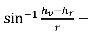
- At 710, an initial elevation angle pair of one of the first elevation angles and one of the second elevation angles is determined using a search algorithm along the line. For example, the
search module 312 may use a greedy search algorithm along the line 140 (e.g., via Equation 3) to determine theinitial angle pair 142. - At 712, the initial elevation angle pair is refined using an NLS method to determine the first elevation angle and the second elevation angle. For example, the
NLS module 136 may apply an NLS method to determine a final elevation angle pair. The NLS method may or may not use theangle grid 144 with precalculated variables. In other words, a traditional NLS method may be applied to determine the final elevation angle pair (e.g., final angle pair 504). - At 714, a height of the object is calculated based on at least one of the first elevation angle or the second elevation angle and the sensor height. For example, the
height module 510 may calculate thetarget height 128 using Equation 9 or 10. -
Fig. 8 is anexample method 800 of NLS using a fixed grid with pre-calculated variables. Theexample method 800 may be implemented in any of the previously described environments, by any of the previously described systems or components, and by utilizing any of the previously described data flows, process flows, or techniques. The order in which the operations are shown and/or described is not intended to be construed as a limitation, and the order may be rearranged without departing from the scope of this disclosure. Furthermore, any number of the operations can be combined with any other number of the operations to implement the example process flow or an alternate process flow - At 802, an initial elevation angle pair of an initial first elevation angle and an initial second elevation angle corresponding to respective signals that have been reflected off an object are received. The first elevation angle corresponding to a direct path reflection from the object, the second elevation angle corresponding to a multipath reflection from the object and a ground. For example, the
NLS module 136 may receive theinitial angle pair 142 corresponding to thefirst signal 108 and thesecond signal 110. Theinitial angle pair 142 may be determined via any number of techniques, including those described in regard toFigs. 1 ,3 ,4 , and7 as well as conventional techniques. - At 804, a grid comprising pre-calculated variables for each of a plurality of grid points is received. The grid points correspond to respective angle pairs of first elevation angles and second elevation angles. For example, the
update module 502 may receive theangle grid 144 which contains the grid points 506 with associated variables 508 (e.g., calculated according to Equations 4). - At 806, the initial elevation angle pair is refined by, for each iteration of one or more iterations: determining a closest grid point to a current elevation angle pair, where the initial elevation angle pair is the current elevation angle pair for a first iteration and performing an NLS iteration on the closest grid point using the pre-calculated variables for the closest grid point to determine a next elevation angle pair. The next elevation angle pair becomes the current elevation angle pair for a next iteration. For example, the
update module 502 may perform NLS iterations (e.g., using Equation 7 or 8) along grid points 506 by usingrespective variables 508 for the grid points to update the Hessian matrices and gradient vectors (e.g., using Equation 5 and Equation 6) starting with agrid point 506 closest to theinitial angle pair 142. - At 808, based on the iterations, a final elevation angle pair is determined. The final elevation angle pair is one of the grid points. For example, the
update module 502 may determine the final angle pair 504 by determining that the NLS iterations have achieved convergence. The final angle pair 504 being one of the grid points 506. - At 810, a height of the object is calculated based on the final elevation angle pair. For example, the
height module 510 may calculate thetarget height 128 using Equation 9 or Equation 10. - Example 1a: A method comprising: receiving, via a sensor and at a first elevation angle relative to a boresight of the sensor, a first signal reflected by an object; receiving, via the sensor and at a second elevation angle relative to the boresight of the sensor, a second signal reflected by the object and a ground plane; determining a range to the object based on at least one of the first signal or the second signal; establishing a maximum height corresponding to an estimated maximum height of the object; establishing a line of second elevation angles as a function of first elevation angles, a sensor height, and the range, wherein the first elevation angles are between a first value based on the sensor height and the range and a second value based on the sensor height, the range, and the maximum height; determining an initial elevation angle pair of one of the first elevation angles and one of the second elevation angles using a search algorithm along the line; refining, using an NLS method, the initial elevation angle pair to determine the first elevation angle and the second elevation angle; and calculating a height of the object based on at least one of the first elevation angle or the second elevation angle and the sensor height.
- Example 2a: The method of example 1a, further comprising performing a vehicle function based on the height of the object.
- Example 3a: The method of example 2a, wherein the vehicle function comprises an advanced driver assist system or autonomous driving function.
- Example 4a: The method of example 1a, wherein the function comprises a negative inverse sin of: a sin of the first elevation angle plus a ratio of twice the sensor height and the range.
- Example 5a: The method of example 1a, wherein the first value comprises a negative inverse sin of a ratio of the sensor height and the range.
- Example 6a: The method of example 1a, wherein the second value comprises an inverse sin of a ratio of a difference between the maximum height and the sensor height and the range.
- Example 7a: The method of example 1a, further comprising determining a misalignment angle between the sensor and the ground plane, wherein: the line of second elevation angles is further a function of the misalignment angle, the first value is based further on the misalignment angle, and the second value is based further on the misalignment angle.
- Example 8a: The method of example 1a, further comprising establishing a minimum height corresponding to an estimated minimum height of the object, wherein the first value is based further on the minimum height.
- Example 9a: The method of example 1a, wherein the search algorithm is a greedy search algorithm.
- Example 10a: The method of example 1a, wherein the maximum height is based on the range.
- Example 11a: The method of example 10a, wherein the maximum height is further based on an azimuth angle of the object.
- Example 12a: The method of example 1a, further comprising receiving a target list of tracked targets, wherein the maximum height is based on the target list.
- Example 13a: The method of example 12a, further comprising: comparing properties of at least one of the first signal or the second signal to properties of the tracked targets in the target list; and responsive to determining that the properties of at least one of the first signal or the second signal match the properties of one of the tracked targets, determining the maximum height based on the properties of the one of the tracked targets.
- Example 14a: The method of example 13a, wherein: the properties of the one of the tracked targets comprise a height of the one of the tracked targets; and the maximum height is set to the height of the one of the tracked targets.
- Example 15a: A system comprising: at least one processor configured to: receive, via a sensor and at a first elevation angle relative to a boresight of the sensor, a first signal reflected by an object; receive, via the sensor and at a second elevation angle relative to the boresight of the sensor, a second signal reflected by the object and a ground plane; determine a range to the object based on at least one of the first signal or the second signal; establish a maximum height corresponding to an estimated maximum height of the object; establish a line of second elevation angles as a function of first elevation angles, a sensor height, and the range, wherein the first elevation angles are between a first value based on the sensor height and the range and a second value based on the sensor height, the range, and the maximum height; determine an initial elevation angle pair of one of the first elevation angles and one of the second elevation angles using a search algorithm along the line; refine, using an NLS method, the initial elevation angle pair to determine the first elevation angle and the second elevation angle; and calculate a height of the object based on at least one of the first elevation angle or the second elevation angle and the sensor height.
- Example 16a: The system of example 15a, further comprising the sensor, wherein the sensor is a radar sensor.
- Example 17a: The system of example 15a, wherein the maximum height is based on the range, an azimuth of the object, or a property in a tracked target list.
- Example 18a: The system of example 15a, wherein the processor is further configured to receive or determine a misalignment angle between the sensor and the ground plane, wherein: the line of second elevation angles is further a function of the misalignment angle, the first value is further based on the misalignment angle, and the second value is further based on the misalignment angle.
- Example 19a: The system of example 15a, wherein the search algorithm is a greedy search algorithm.
- Example 20a: A non-transitory computer-readable storage media comprising instructions that, when executed, cause at least one processor to: receive, via a sensor and at a first elevation angle relative to a boresight of the sensor, a first signal reflected by an object; receive, via the sensor and at a second elevation angle relative to the boresight of the sensor, a second signal reflected by the object and a ground plane; determine a range to the object based on at least one of the first signal or the second signal; establish a maximum height corresponding to an estimated maximum height of the object; establish a line of second elevation angles as a function of first elevation angles, a sensor height, and the range, wherein the first elevation angles are between a first value based on the sensor height and the range and a second value based on the sensor height, the range, and the maximum height; determine an initial elevation angle pair of one of the first elevation angles and one of the second elevation angles using a search algorithm along the line; refine, using an NLS method, the initial elevation angle pair to determine the first elevation angle and the second elevation angle; and calculate a height of the object based on at least one of the first elevation angle or the second elevation angle and the sensor height.
- Example 1b: A method comprising: receiving an initial elevation angle pair including an initial first elevation angle and an initial second elevation angle corresponding to respective signals from an object, the initial first elevation angle corresponding to a direct path reflection from the object, the initial second elevation angle corresponding to a multipath reflection from the object and a ground; receiving a grid comprising pre-calculated variables for each of a plurality of grid points, the grid points corresponding to respective angle pairs of possible first and second elevation angles; refining the initial elevation angle pair by: for a first iteration: determining a first closest grid point to the initial elevation angle pair; performing an NLS iteration on the first closest grid point using the pre-calculated variables for the first closest grid point to determine a second elevation angle pair; and determining a second closest grid point to the second elevation angle pair; and for each subsequent iteration of one or more subsequent iterations: performing an NLS iteration on a current grid point using the pre-calculated variables for the current grid point to determine a next elevation angle pair, the current grid point being the second closest grid point for a first subsequent iteration; and determining a subsequent closest grid point to the next elevation angle pair, the subsequent closest grid point becoming the current grid point for a next iteration; and determining, based on the iterations, a final subsequent closest grid point as a final elevation angle pair; and calculating a height of the object based on the final elevation angle pair.
- Example 2b: The method of example 1b, wherein the NLS iteration uses only linear operations.
- Example 3b: The method of example 1b, wherein the NLS iteration comprises calculating a Hessian matrix and a gradient vector using the pre-calculated variables and a measurement matrix corresponding to the respective signals.
- Example 4b: The method of example 3b, wherein the NLS iteration further comprises using the Hessian matrix and the gradient vector to determine an offset from the closest grid point.
- Example 5b: The method of example 4b, wherein the offset comprises a function of the Hessian matrix, the gradient vector, and a damping factor.
- Example 6b: The method of example 5b, wherein the NLS iteration comprises a line search or a trust region function.
- Example 7b: The method of example 1b, wherein the pre-calculated variables comprise four variables.
- Example 8b: The method of example 7b, wherein the pre-calculated variables comprise: a first variable based on a first derivative of a steering matrix and the steering matrix; a second variable based on the steering matrix; a third variable based on the first derivative of the steering matrix and the steering matrix; a fourth variable based on the steering matrix.
- Example 9b: The method of example 1b, wherein one of the pre-calculated variables comprises a pseudoinverse of a steering matrix.
- Example 10b: The method of example 1b, wherein one of the pre-calculated variables comprises a product of a conjugate transpose of a first derivative of a steering matrix and a function that projects a measurement matrix onto an orthogonal complement of a column space of the steering matrix.
- Example 11b: The method of example 10b, wherein another of the pre-calculated variables comprises a product of the conjugate transpose of the first derivative of the steering matrix, the function, and the first derivative of the steering matrix.
- Example 12b: The method of example 1b, wherein one of the pre-calculated variables comprises an inverse of a product of a conjugate transpose of a steering matrix and the steering matrix.
- Example 13b: The method of example 1b, wherein the subsequent iterations are performed until the subsequent closest grid point is the current grid point.
- Example 14b: The method of example 1b, wherein the respective signals are radar signals.
- Example 15b: A system comprising: at least one processor configured to: receive an initial elevation angle pair including an initial first elevation angle and an initial second elevation angle corresponding to respective signals from an object, the initial first elevation angle corresponding to a direct path reflection from the object, the initial second elevation angle corresponding to a multipath reflection from the object and a ground; receive a grid comprising pre-calculated variables for each of a plurality of grid points, the grid points corresponding to respective angle pairs of possible first and second elevation angles; refine the initial elevation angle pair by: for a first iteration: determining a first closest grid point to the initial elevation angle pair; performing an NLS iteration on the first closest grid point using the pre-calculated variables for the first closest grid point to determine a second elevation angle pair; and determining a second closest grid point to the second elevation angle pair; and for each subsequent iteration of one or more subsequent iterations: performing an NLS iteration on a current grid point using the precalculated variables for the current grid point to determine a next elevation angle pair, the current grid point being the second closest grid point for a first subsequent iteration; and determining a subsequent closest grid point to the next elevation angle pair, the subsequent closest grid point becoming the current grid point for a next iteration; and determine, based on the iterations, a final subsequent closest grid point as a final elevation angle pair; and calculate a height of the object based on the final elevation angle pair.
- Example 16b: The system of example 15b, wherein the NLS iteration uses only linear operations.
- Example 17b: The system of example 15b, wherein the NLS iteration comprises calculating a Hessian matrix and a gradient vector using the pre-calculated variables and a measurement matrix corresponding to the respective signals.
- Example 18b: The system of example 15b, wherein the subsequent iterations are performed until the subsequent closest grid point is the current grid point.
- Example 19b: The system of example 15b, wherein at least one of: one of the precalculated variables comprises a pseudoinverse of a steering matrix; one of the pre-calculated variables comprises a product of a conjugate transpose of a first derivative of the steering matrix and a function that projects a measurement matrix onto an orthogonal complement of a column space of the steering matrix; one of the pre-calculated variables comprises a product of the conjugate transpose of the first derivative of the steering matrix, the function, and the first derivative of the steering matrix; or one of the pre-calculated variables comprises an inverse of a product of the conjugate transpose of the steering matrix and the steering matrix.
- Example 20b: A non-transitory computer-readable storage media comprising instructions that, when executed, cause at least one processor to: receive an initial elevation angle pair including an initial first elevation angle and an initial second elevation angle corresponding to respective signals from an object, the initial first elevation angle corresponding to a direct path reflection from the object, the initial second elevation angle corresponding to a multipath reflection from the object and a ground; receive a grid comprising pre-calculated variables for each of a plurality of grid points, the grid points corresponding to respective angle pairs of possible first and second elevation angles; refine the initial elevation angle pair by: for a first iteration: determining a first closest grid point to the initial elevation angle pair; performing an NLS iteration on the first closest grid point using the pre-calculated variables for the first closest grid point to determine a second elevation angle pair; and determining a second closest grid point to the second elevation angle pair; and for each subsequent iteration of one or more subsequent iterations: performing an NLS iteration on a current grid point using the pre-calculated variables for the current grid point to determine a next elevation angle pair, the current grid point being the second closest grid point for a first subsequent iteration; and determining a subsequent closest grid point to the next elevation angle pair, the subsequent closest grid point becoming the current grid point for a next iteration; and determine, based on the iterations, a final subsequent closest grid point as a final elevation angle pair; and calculate a height of the object based on the final elevation angle pair.
- While various embodiments of the disclosure are described in the foregoing description and shown in the drawings, it is to be understood that this disclosure is not limited thereto but may be variously embodied to practice within the scope of the following claims. From the foregoing description, it will be apparent that various changes may be made without departing from the spirit and scope of the disclosure as defined by the following claims.
- The use of "or" and grammatically related terms indicates non-exclusive alternatives without limitation unless the context clearly dictates otherwise. As used herein, a phrase referring to "at least one of" a list of items refers to any combination of those items, including single members. As an example, "at least one of: a, b, or c" is intended to cover a, b, c, a-b, a-c, b-c, and a-b-c, as well as any combination with multiples of the same element (e.g., a-a, a-a-a, a-a-b, a-a-c, a-b-b, a-c-c, b-b, b-b-b, b-b-c, c-c, and c-c-c or any other ordering of a, b, and c).
Claims (15)
- A method comprising:receiving, via a sensor and at a first elevation angle relative to a boresight of the sensor, a first signal reflected by an object;receiving, via the sensor and at a second elevation angle relative to the boresight of the sensor, a second signal reflected by the object and a ground plane;determining a range to the object based on at least one of the first signal or the second signal;establishing a maximum height corresponding to an estimated maximum height of the object;establishing a line of second elevation angles as a function of first elevation angles, a sensor height, and the range, wherein the first elevation angles are between a first value based on the sensor height and the range and a second value based on the sensor height, the range, and the maximum height;determining an initial elevation angle pair of one of the first elevation angles and one of the second elevation angles using a search algorithm along the line;refining, using a non-linear least squares method, the initial elevation angle pair to determine the first elevation angle and the second elevation angle; andcalculating a height of the object based on at least one of the first elevation angle or the second elevation angle and the sensor height.
- The method of claim 1, further comprising performing a vehicle function based on the height of the object.
- The method of claim 2, wherein the vehicle function comprises an advanced driver assist system or autonomous driving function.
- The method of any preceding claim, wherein the function comprises a negative inverse sin of: a sin of the first elevation angle plus a ratio of twice the sensor height and the range.
- The method of any preceding claim, wherein the first value comprises a negative inverse sin of a ratio of the sensor height and the range.
- The method of any preceding claim, wherein the second value comprises an inverse sin of a ratio of a difference between the maximum height and the sensor height and the range.
- The method of any preceding claim, further comprising determining a misalignment angle between the sensor and the ground plane, wherein:the line of second elevation angles is further a function of the misalignment angle,the first value is based further on the misalignment angle, andthe second value is based further on the misalignment angle.
- The method of any preceding claim, further comprising establishing a minimum height corresponding to an estimated minimum height of the object, wherein the first value is based further on the minimum height.
- The method of any preceding claim, wherein the search algorithm is a greedy search algorithm.
- The method of any preceding claim, wherein the maximum height is based on the range.
- The method of claim 10, wherein the maximum height is further based on an azimuth angle of the object.
- The method of any preceding claim, further comprising receiving a target list of tracked targets, wherein the maximum height is based on the target list.
- The method of claim 12, further comprising:comparing properties of at least one of the first signal or the second signal to properties of the tracked targets in the target list; andresponsive to determining that the properties of at least one of the first signal or the second signal match the properties of one of the tracked targets, determining the maximum height based on the properties of the one of the tracked targets.
- The method of claim 13, wherein:the properties of the one of the tracked targets comprise a height of the one of the tracked targets; andthe maximum height is set to the height of the one of the tracked targets.
- A system comprising at least one processor configured to perform the method of any of claims 1-14.
Applications Claiming Priority (1)
| Application Number | Priority Date | Filing Date | Title |
|---|---|---|---|
| US18/360,682 US12365343B2 (en) | 2023-07-27 | 2023-07-27 | NLS using a bounded linear initial search space and a fixed grid with pre-calculated variables |
Publications (1)
| Publication Number | Publication Date |
|---|---|
| EP4498114A1 true EP4498114A1 (en) | 2025-01-29 |
Family
ID=87889068
Family Applications (1)
| Application Number | Title | Priority Date | Filing Date |
|---|---|---|---|
| EP23194702.9A Pending EP4498114A1 (en) | 2023-07-27 | 2023-08-31 | Nls using a bounded linear initial search space and a fixed grid with pre-calculated variables |
Country Status (3)
| Country | Link |
|---|---|
| US (1) | US12365343B2 (en) |
| EP (1) | EP4498114A1 (en) |
| CN (1) | CN119377537A (en) |
Citations (2)
| Publication number | Priority date | Publication date | Assignee | Title |
|---|---|---|---|---|
| EP3767333A1 (en) * | 2019-07-16 | 2021-01-20 | Nxp B.V. | Method and system for height estimation in ultra-short-range radar |
| EP4075161A1 (en) * | 2021-04-13 | 2022-10-19 | Aptiv Technologies Limited | Method of estimating target height by detection device |
Family Cites Families (4)
| Publication number | Priority date | Publication date | Assignee | Title |
|---|---|---|---|---|
| JP6011489B2 (en) * | 2013-08-26 | 2016-10-19 | トヨタ自動車株式会社 | In-vehicle control device |
| DE102014201026A1 (en) | 2014-01-21 | 2015-07-23 | Robert Bosch Gmbh | Method for angle estimation and radar sensor for motor vehicles |
| DE102016207871A1 (en) | 2016-05-09 | 2017-11-09 | Robert Bosch Gmbh | Azimuth determination by means of a radar sensor |
| US11454705B2 (en) | 2019-02-22 | 2022-09-27 | Veoneer Us, Llc | Tracking system and method for characterizing target height using percentage of range bins |
-
2023
- 2023-07-27 US US18/360,682 patent/US12365343B2/en active Active
- 2023-08-31 EP EP23194702.9A patent/EP4498114A1/en active Pending
- 2023-10-24 CN CN202311389924.0A patent/CN119377537A/en active Pending
Patent Citations (2)
| Publication number | Priority date | Publication date | Assignee | Title |
|---|---|---|---|---|
| EP3767333A1 (en) * | 2019-07-16 | 2021-01-20 | Nxp B.V. | Method and system for height estimation in ultra-short-range radar |
| EP4075161A1 (en) * | 2021-04-13 | 2022-10-19 | Aptiv Technologies Limited | Method of estimating target height by detection device |
Non-Patent Citations (3)
| Title |
|---|
| LARIBI AMIR ET AL: "A new height-estimation method using FMCW radar Doppler beam sharpening", 2017 25TH EUROPEAN SIGNAL PROCESSING CONFERENCE (EUSIPCO), EURASIP, 28 August 2017 (2017-08-28), pages 1932 - 1396, XP033236275, [retrieved on 20171023], DOI: 10.23919/EUSIPCO.2017.8081546 * |
| SHISHANOV SERGEI ET AL: "Road Object Height Estimation Using Multipath Effect in Automotive Radar Measurements", 2023 24TH INTERNATIONAL RADAR SYMPOSIUM (IRS), GERMAN INSTITUTE OF NAVIGATION (DGON), 24 May 2023 (2023-05-24), pages 1 - 7, XP034375699, [retrieved on 20230711], DOI: 10.23919/IRS57608.2023.10172404 * |
| ZHUANG ZHENRUI ET AL: "UAV Localization Using Staring Radar Under Multipath Interference", IGARSS 2022 - 2022 IEEE INTERNATIONAL GEOSCIENCE AND REMOTE SENSING SYMPOSIUM, IEEE, 17 July 2022 (2022-07-17), pages 2291 - 2294, XP034194288, [retrieved on 20220928], DOI: 10.1109/IGARSS46834.2022.9884358 * |
Also Published As
| Publication number | Publication date |
|---|---|
| US20250033644A1 (en) | 2025-01-30 |
| US12365343B2 (en) | 2025-07-22 |
| CN119377537A (en) | 2025-01-28 |
Similar Documents
| Publication | Publication Date | Title |
|---|---|---|
| EP3285230B1 (en) | Enhanced object detection and motion estimation for a vehicle environment detection system | |
| EP1631843B1 (en) | Object detection system and method of detecting object | |
| EP2894601B1 (en) | Method for analyzing related images, image processing system, vehicle comprising such system and computer program product | |
| Schuster et al. | Probabilistic data association for tracking extended targets under clutter using random matrices | |
| EP4231051B1 (en) | Multi-scan sensor fusion for object tracking | |
| EP1835463A2 (en) | Obstacle tracking apparatus and method | |
| EP2144038A2 (en) | Inertial measurement using an imaging sensor and a digitized map | |
| US10613196B2 (en) | Apparatus for processing signals of radar and method for processing signals thereof | |
| EP3499265B1 (en) | Determining object motion and acceleration vector in a vehicle radar system | |
| EP3588135B1 (en) | Method of determining an alignment error of an antenna and vehicle with an antenna and a detection device | |
| US11994577B2 (en) | Object tracking device | |
| US20190266421A1 (en) | System and method for detecting close cut-in vehicle based on free space signal | |
| US7804445B1 (en) | Method and apparatus for determination of range and direction for a multiple tone phased array radar in a multipath environment | |
| EP4498118A1 (en) | Nls using a bounded linear initial search space and a fixed grid with pre- calculated variables | |
| US12365343B2 (en) | NLS using a bounded linear initial search space and a fixed grid with pre-calculated variables | |
| Page et al. | Detection and tracking of moving vehicles with Gotcha radar systems | |
| US9465102B2 (en) | Apparatus, method, and computer readable medium for correcting an interpolation coefficient for stereo matching | |
| US20230384440A1 (en) | Super-Resolution Based on Iterative Multiple-Source Angle-of-Arrival Estimation | |
| US10725143B2 (en) | 3D direction finding method and device therefore | |
| EP4191273A1 (en) | Multi-channel joint interference mitigation | |
| CN113140130B (en) | Object detection device and vehicle control system including the object detection device | |
| JP2004212187A (en) | Image radar device | |
| US20210199752A1 (en) | System and method for intercepting an exo-atmospheric target using passive ranging estimation | |
| EP4184207A1 (en) | Method and apparatus for determination of direction of arrival angle | |
| CN117630831A (en) | Rate estimation and angular offset correction in SAR images by performing image matching |
Legal Events
| Date | Code | Title | Description |
|---|---|---|---|
| PUAI | Public reference made under article 153(3) epc to a published international application that has entered the european phase |
Free format text: ORIGINAL CODE: 0009012 |
|
| STAA | Information on the status of an ep patent application or granted ep patent |
Free format text: STATUS: THE APPLICATION HAS BEEN PUBLISHED |
|
| AK | Designated contracting states |
Kind code of ref document: A1 Designated state(s): AL AT BE BG CH CY CZ DE DK EE ES FI FR GB GR HR HU IE IS IT LI LT LU LV MC ME MK MT NL NO PL PT RO RS SE SI SK SM TR |
|
| STAA | Information on the status of an ep patent application or granted ep patent |
Free format text: STATUS: REQUEST FOR EXAMINATION WAS MADE |
|
| 17P | Request for examination filed |
Effective date: 20250722 |
|
| STAA | Information on the status of an ep patent application or granted ep patent |
Free format text: STATUS: EXAMINATION IS IN PROGRESS |
|
| 17Q | First examination report despatched |
Effective date: 20251219 |