EP4498095A1 - Method and apparatus for detecting a collision between an obstacle and a moving vehicle - Google Patents
Method and apparatus for detecting a collision between an obstacle and a moving vehicle Download PDFInfo
- Publication number
- EP4498095A1 EP4498095A1 EP23188428.9A EP23188428A EP4498095A1 EP 4498095 A1 EP4498095 A1 EP 4498095A1 EP 23188428 A EP23188428 A EP 23188428A EP 4498095 A1 EP4498095 A1 EP 4498095A1
- Authority
- EP
- European Patent Office
- Prior art keywords
- vehicle
- time interval
- sensor data
- time
- acceleration
- Prior art date
- Legal status (The legal status is an assumption and is not a legal conclusion. Google has not performed a legal analysis and makes no representation as to the accuracy of the status listed.)
- Pending
Links
Images
Classifications
-
- G—PHYSICS
- G01—MEASURING; TESTING
- G01P—MEASURING LINEAR OR ANGULAR SPEED, ACCELERATION, DECELERATION, OR SHOCK; INDICATING PRESENCE, ABSENCE, OR DIRECTION, OF MOVEMENT
- G01P15/00—Measuring acceleration; Measuring deceleration; Measuring shock, i.e. sudden change of acceleration
- G01P15/02—Measuring acceleration; Measuring deceleration; Measuring shock, i.e. sudden change of acceleration by making use of inertia forces using solid seismic masses
- G01P15/08—Measuring acceleration; Measuring deceleration; Measuring shock, i.e. sudden change of acceleration by making use of inertia forces using solid seismic masses with conversion into electric or magnetic values
- G01P15/0891—Measuring acceleration; Measuring deceleration; Measuring shock, i.e. sudden change of acceleration by making use of inertia forces using solid seismic masses with conversion into electric or magnetic values with indication of predetermined acceleration values
-
- G—PHYSICS
- G06—COMPUTING OR CALCULATING; COUNTING
- G06N—COMPUTING ARRANGEMENTS BASED ON SPECIFIC COMPUTATIONAL MODELS
- G06N20/00—Machine learning
-
- G—PHYSICS
- G06—COMPUTING OR CALCULATING; COUNTING
- G06N—COMPUTING ARRANGEMENTS BASED ON SPECIFIC COMPUTATIONAL MODELS
- G06N20/00—Machine learning
- G06N20/10—Machine learning using kernel methods, e.g. support vector machines [SVM]
-
- G—PHYSICS
- G06—COMPUTING OR CALCULATING; COUNTING
- G06N—COMPUTING ARRANGEMENTS BASED ON SPECIFIC COMPUTATIONAL MODELS
- G06N3/00—Computing arrangements based on biological models
- G06N3/02—Neural networks
- G06N3/08—Learning methods
-
- G—PHYSICS
- G08—SIGNALLING
- G08G—TRAFFIC CONTROL SYSTEMS
- G08G1/00—Traffic control systems for road vehicles
- G08G1/01—Detecting movement of traffic to be counted or controlled
- G08G1/0104—Measuring and analyzing of parameters relative to traffic conditions
- G08G1/0108—Measuring and analyzing of parameters relative to traffic conditions based on the source of data
- G08G1/0112—Measuring and analyzing of parameters relative to traffic conditions based on the source of data from the vehicle, e.g. floating car data [FCD]
-
- G—PHYSICS
- G08—SIGNALLING
- G08G—TRAFFIC CONTROL SYSTEMS
- G08G1/00—Traffic control systems for road vehicles
- G08G1/01—Detecting movement of traffic to be counted or controlled
- G08G1/0104—Measuring and analyzing of parameters relative to traffic conditions
- G08G1/0125—Traffic data processing
- G08G1/0133—Traffic data processing for classifying traffic situation
-
- G—PHYSICS
- G08—SIGNALLING
- G08G—TRAFFIC CONTROL SYSTEMS
- G08G1/00—Traffic control systems for road vehicles
- G08G1/16—Anti-collision systems
- G08G1/165—Anti-collision systems for passive traffic, e.g. including static obstacles, trees
-
- G—PHYSICS
- G08—SIGNALLING
- G08G—TRAFFIC CONTROL SYSTEMS
- G08G1/00—Traffic control systems for road vehicles
- G08G1/16—Anti-collision systems
- G08G1/166—Anti-collision systems for active traffic, e.g. moving vehicles, pedestrians, bikes
-
- G—PHYSICS
- G08—SIGNALLING
- G08G—TRAFFIC CONTROL SYSTEMS
- G08G1/00—Traffic control systems for road vehicles
- G08G1/01—Detecting movement of traffic to be counted or controlled
- G08G1/0104—Measuring and analyzing of parameters relative to traffic conditions
- G08G1/0137—Measuring and analyzing of parameters relative to traffic conditions for specific applications
- G08G1/0141—Measuring and analyzing of parameters relative to traffic conditions for specific applications for traffic information dissemination
Definitions
- the present disclosure relates to the field of vehicle control systems and, more particularly, to a method for detecting a collision between an obstacle and a moving vehicle.
- ADAS Advanced Driver Assistance Systems
- driver assistance systems have been designed to guide the driver and assist him in risk anticipation by automating, improving, or adapting some or all of the tasks related to driving a vehicle.
- the driver can be relieved of tasks that may distract him.
- driver assistance systems rely generally on sensors to assist the driver throughout their journey and often communicate with a server to receive real-time information along the vehicle's route.
- Modern assistance driver systems also provide additional information related to the route, such as weather conditions, traffic congestion, duration, and disruptions on the road (diversions or lane closures, for example).
- the driver assistance system can also be configured to provide information, including regulatory indications, such as speed limits or the presence of checkpoints.
- Driver assistance may further encompass secondary tasks such as location finding and obstacle detection.
- secondary tasks such as location finding and obstacle detection.
- it enables the anticipation of potential collisions, such as with stationary obstacles (traffic barriers, signs, or trees, for example) or with moving obstacles like other vehicles.
- the detection of such accident subsequently enables the driver assistance system to alert emergency services in case of passenger's injuries and/or to notify the vehicle's manufacturer about damages that have occurred and their location for repair purpose.
- Such collision is considered as a "minor” collision which refers to a low-impact accident where the resulting damage does not significantly affect the drivability or the safety of the vehicle.
- a minor collision may involve a low-speed incident wherein the vehicle makes contact with an obstacle, resulting in superficial damage.
- the object of the present invention is to at least substantially remedy the above-mentioned drawbacks.
- the present disclosure relates to a computer-implemented method for detecting a collision between at least one obstacle and a moving vehicle by a machine learning classification model, the method comprising:
- the method is referred to hereinafter as the collision detection method.
- the "at least one on-vehicle sensor” comprises one on-vehicle sensor or a plurality of on-vehicle sensors.
- the on-vehicle sensor may be integrated into the vehicle to collect data about its surroundings or internal systems.
- the obtained sensor data provides information about the acceleration values of the vehicle.
- the sensor data is time-series data that is collected at a plurality of corresponding timings.
- the sensor data is collected on sampling times, i.e. at specific intervals or time points.
- Sensor data is then collected periodically with a regular time interval.
- the on-vehicle sensor may measure 700 accelerations through 7 seconds and may store them to provide them as a time-series of 700 accelerations.
- the sensor data is then collected every 7 seconds.
- the sensor data may be collected during other periods as 15 seconds, 13 seconds, 10 seconds or 5 seconds for example. Such periods may be set by a person skilled in the art based on the computing resources of the vehicle.
- the on-vehicle sensor may be an accelerometer that may detect changes in the vehicle's speed along three perpendicular axes and then may determine the acceleration in these directions.
- Collecting sensor data as time-series helps to identify if a peak acceleration value among said acceleration values is greater than a predetermined threshold. If that is the case, the first, second and third sets of sensor data as defined above provide information about the driver's reaction, e.g. aggressive driving. It is then possible to distinguish between acceleration due to a minor collision and acceleration that does not incur in vehicle damage and that may be caused for example by aggressive driving, bad road conditions, i.e. potholes, bricks or other road irregularities such as speedbumps that may cause discomfort to the passengers.
- the first, second and third sets of sensor data are processed in order to extract time-series statistical data over the first, second and third time interval, noting that a time-series statistical data may refer to a collection of data points recorded over a time interval.
- a time-series statistical data may refer to a collection of data points recorded over a time interval.
- the term "statistical data” may refer to statistical values such as a maximum value among an extracted set of sensor data values or an average value of the extracted set of sensor data.
- only data that comprises substantive information intended to distinguish between acceleration due to a minor collision and acceleration that does not incur in vehicle damage, are provided to the machine learning classification model.
- the machine learning classification model is then trained to execute a function of determining whether the peak acceleration value is representative of a collision between the moving vehicle and an obstacle.
- machine learning classification models there are different machine learning classification models able to execute such function. They may select the architecture of the machine learning classification model based on the computing resources available in the vehicle for example.
- the collected acceleration value comprises a longitudinal acceleration value and a lateral acceleration value
- the collected sensor data further comprise a yaw rate of the vehicle, a speed value of the vehicle, a position of an accelerator pedal of the vehicle, a pressure value of a brake master cylinder of the vehicle and a value of a steering angle speed of the vehicle.
- the longitudinal acceleration may refer to the acceleration experienced by the vehicle in the direction of its motion, either as forward acceleration or deceleration, when the lateral acceleration may refer to the acceleration experienced by the vehicle in a direction perpendicular to its motion, commonly experienced during cornering or turning.
- an on-vehicle accelerometer or a wheel speed sensor may be used. More precisely, the accelerometer may measure changes in velocity along a longitudinal axis that is parallel to the motion direction of the vehicle, while the wheel speed sensor may measure changes in wheel speeds which is directly related to the change in the vehicle's velocity.
- the lateral acceleration value may be obtained by the same on-vehicle accelerometer that may measure changes in velocity along a perpendicular axis to the motion direction of the vehicle.
- the lateral acceleration may be provided by a gyroscope that may measure the vehicle's angular velocity which helps to determine the lateral acceleration when the vehicle undergoes rotational motion during cornering for example.
- the other collected sensor data defined above are also provided by on-vehicle sensors.
- the yaw rate may be provided by the on-vehicle gyroscope when the position of the accelerator pedal may be provided by an on-vehicle throttle position sensor.
- the processing step comprises filtering said first, second and third sets of sensor data before extracting the first, second and third time-series statistical data.
- the collected data may be noisy or may contain missing values, outliers and errors. Filtering the first, second and third sets of sensor data may thus involve removing or correcting these issues. Filtering such sets of sensor data may also include normalizing and/or scaling them in order to bring them to a common scale.
- the predetermined threshold is set between 0.3G and 0.6G.
- the unit “G” refers to the acceleration due to gravity. More precisely, 1G is equivalent to the standard acceleration due to gravity on the surface of the Earth, which is approximately 9.81 meters per second squared (m/s 2 ).
- the first time interval comprises a first sub-interval prior and adjacent to the corresponding timing of the acceleration peak and a second sub-interval subsequent and adjacent to the corresponding timing of the acceleration peak, the first time interval corresponding to a sum in time of the first sub-interval and the second sub-interval.
- the first sub-interval and the second sub-interval are sub-intervals around the acceleration peak.
- the sum in time of the first sub-interval and the second sub-interval may be set between 1 and 3 seconds.
- the person skilled in the art is able to choose the duration of the first and the second sub-intervals to obtain this sum.
- the second time interval is set between 2 and 5 seconds, and wherein the third time interval is set between 2 and 10 seconds.
- the sensor data are collected from the at least one sensor via a controller area network bus.
- the at least one obstacle is a stationary obstacle or a moving obstacle.
- the "stationary obstacle” is fixed or immobile in the vehicle's surroundings, such as parked cars, traffic barriers, road signs, buildings, or trees. While the stationary obstacle is not currently obstructing the vehicle's path, it has the potential to become an obstacle that may cause a collision with the moving vehicle if it approaches it too closely or deviates from its intended path.
- the "moving obstacle” is in motion within the vehicle's surroundings, including other vehicles, pedestrians, cyclists, or animals. This moving obstacle has the potential to intersect with the vehicle's path and create a collision risk if their trajectories converge.
- the present disclosure further relates to a computer program set including instructions for executing the steps of the above-described computer-implemented method when said program set is executed by one computer.
- This program set can use any programming language and take the form of source code, object code, or a code intermediate between source code and object code, such as a partially compiled form or any other desirable form.
- the present disclosure further relates to an apparatus for detecting a collision between at least one obstacle and a moving vehicle by an on-vehicle machine learning classification model, the apparatus comprising:
- the apparatus referred to hereinafter as the collision detection apparatus may be configured to carry out the above-mentioned collision detection method and may have part or all of the above-described features.
- the collision detection apparatus may have the hardware structure of a computer.
- the present disclosure also relates to a vehicle comprising an apparatus for detecting a collision, as described above.
- vehicle may be directed to an apparatus capable of transporting people or objects from one location to another, such as a car or a motorcycle.
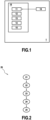
- FIG. 1 shows a block diagram of a collision detection apparatus 10 comprising a collecting module 11, a delimiting module 12, an extracting module 13, a processing module 15, and an applying module 14 according to embodiments of the present disclosure.
- the collision detection apparatus 10 may be located inside a vehicle 1 which may be, without limitation, an autonomous or semi-autonomous vehicle.
- the collision detection apparatus 10 may be configured to detect a collision between at least one obstacle and the vehicle 1 during its motion by an on-vehicle machine learning classification model.
- Such collision is considered minor when it refers to a low-impact accident where the resulting damage does not significantly affect the drivability or the safety of the vehicle 1.
- a minor collision may involve a low-speed incident wherein the vehicle 1 makes contact with an obstacle, resulting in superficial damage.
- a minor collision may occur due to a collision with another vehicle wherein the force of the impact is not high enough to trigger airbag deployment, but enough to induce damage to the vehicles. It is then difficult to detect this collision as it may be confounded with an acceleration that does not incur in vehicle damage caused for example by aggressive driving, bad road conditions, i.e. potholes, bricks or other road irregularities such as speedbumps that may cause discomfort to the passengers.
- the collision detection apparatus 10 is configured to distinguish between acceleration due to a minor collision and acceleration that does not incur in vehicle damage.
- Such vehicle 1 may be directed to an apparatus capable of transporting people from one location to another, such as a car or a motorcycle, and may be categorized into different levels based on the extent of automation and human involvement in the driving tasks.
- the collision detection apparatus 10 may comprise an electronic circuit, a processor (shared, dedicated, or group), a combinational logic circuit, a memory that executes one or more software programs, and/or other suitable components that provide the described functionality.
- the collision detection apparatus 10 may be a computer device.
- the collision detection apparatus 10 may be connected to a memory, which may store data, e.g. at least one computer program, which, when executed, carries out the collision detection method according to the present disclosure.
- the memory can be a ROM (for "Read Only Memory”), a CD ROM, a microelectronic circuit ROM, or in the form of magnetic storage means, for example, a diskette (floppy disk), a flash disk, a SSD (for "Solid State Drive”) or a hard disk.
- ROM Read Only Memory
- CD ROM Compact Disc ROM
- microelectronic circuit ROM or in the form of magnetic storage means, for example, a diskette (floppy disk), a flash disk, a SSD (for "Solid State Drive”) or a hard disk.
- the memory can be an integrated circuit in which the program is incorporated, the circuit being adapted to execute the collision detection method or to be used in its execution.
- the collecting module 11 is a module for collecting sensor data, comprising acceleration values, from at least one on-vehicle sensor 18 at a plurality of corresponding timings during motion of the vehicle 1 (the moving vehicle). Such sensor data are collected from the on-vehicle sensor 18 via a controller area network bus (commonly named CAN).
- CAN controller area network bus
- the sensor data provides information about the acceleration values of the vehicle 1.
- the sensor data is time-series data that is collected at a plurality of corresponding timings. In other words, the sensor data is collected on sampling times, i.e. at specific intervals or time points. Sensor data is then collected periodically with a regular time interval.
- the on-vehicle sensor 18 may measure 700 accelerations through 7 seconds and may store them in a memory to provide them as a time-series of 700 accelerations. The sensor data is then collected every 7 seconds. Of course, the sensor data may be collected during other periods as 15 seconds, 13 seconds, 10 seconds or 5 seconds. These periods may be set by a person skilled in the art based on the computing resources for example.
- the on-vehicle sensor 18 may be an accelerometer that may detect changes in the vehicle's speed along three perpendicular axes and then may determine the acceleration in these directions.
- the collecting module 11 may collect a longitudinal acceleration value and a lateral acceleration value. More precisely, the longitudinal acceleration may refer to the acceleration experienced by the vehicle 1 in the direction of its motion, either as forward acceleration or deceleration, when the lateral acceleration may refer to the acceleration experienced by the vehicle 1 in a direction perpendicular to its motion, commonly experienced during cornering or turning.
- the accelerometer may thus measure changes in velocity along a longitudinal axis that is parallel to the motion direction of the vehicle 1 to obtain the longitudinal acceleration value, when it measures changes in velocity along a perpendicular axis to the motion direction of the vehicle 1 to obtain the lateral acceleration value.
- acceleration values i.e. the longitudinal acceleration and the lateral acceleration, directly or indirectly following series of calculations.
- the collecting module 11 may be configured to further collect sensor data comprising a yaw rate of the vehicle 1, a speed value of the vehicle 1, a position of an accelerator pedal of the vehicle 1, a pressure value of a brake master cylinder of the vehicle 1 and a value of a steering angle speed of the vehicle 1.
- the yaw rate may be provided by the gyroscope as the on-vehicle sensor 18 when the position of the accelerator pedal may be provided by an on-vehicle throttle position sensor as the on-vehicle sensor 18.
- the receiving module 11 may be implemented as software running on the collision detection apparatus 10 or may be implemented partially or fully as a hardware element of the collision detection apparatus 10.
- the delimiting module 12 is a module for delimiting, when a peak acceleration value among said acceleration values is greater than a predetermined threshold, a first time interval comprising the corresponding timing of the peak acceleration value.
- the delimiting module 12 may be implemented as software running on the driver collision detection apparatus 10 or may be implemented partially or fully as a hardware element of the collision detection apparatus 10.
- the driver collision detection 10 may comprise a program that includes both the collecting module 11 and the delimiting module 12.
- the collecting module 11 may be realized as an independent program (in particular, beside a program forming the delimiting module 12).
- Collecting sensor data as time-series helps to identify if a peak acceleration value among said acceleration values is greater than the predetermined threshold which means that the peak acceleration value is not usual when driving.
- the delimiting module 12 is then configured for delimiting the first time interval comprising the corresponding timing of the peak acceleration value by dividing in it into a first sub-interval prior and adjacent to the corresponding timing of the acceleration peak and a second sub-interval subsequent and adjacent to the corresponding timing of the acceleration peak.
- first sub-interval and the second sub-interval are sub-intervals around the acceleration peak.
- the sum in time of the first sub-interval and the second sub-interval may be set between 1 and 3 seconds.
- the person skilled in the art is able to choose the duration of the first and the second sub-intervals to obtain this sum.
- identifying the peak acceleration value is not sufficient to detect a minor collision between an obstacle and the moving vehicle 1.
- the peak acceleration value even being greater than the predetermined threshold, can be confused with a usual acceleration if the driver has an aggressive driving for example. It is then advantageous to collect said sensor data before and after the occurrence of the peak acceleration value that is greater than the predetermined threshold in order to characterize the driver's behaviour.
- the extracting module 13 is a module for extracting a first set of sensor data during the first time interval, a second set of sensor data collected during a second time interval prior and adjacent to the first time interval, and a third set of sensor data collected during a third time interval subsequent and adjacent to the first time interval.
- the second time interval may be set between 2 and 5 seconds, and the third time interval may be set between 2 and 10 seconds.
- the extracting module 13 may be implemented as software running on the collision detection apparatus 10 and may also be implemented partially or fully on the collision detection apparatus 10 as a hardware element of the collision detection apparatus 10.
- the extracting module 13 may comprise a program that includes together the collecting module 11 and the delimiting module 12.
- the extracting module 13 may be realized as an independent program (in particular, beside a program forming both the collecting module 11 and the delimiting module 12, or beside a program forming the delimiting module 12 and beside a program forming the collecting module 11).
- the processing module 15 is a module for processing the first set of sensor data in order to extract a first time-series statistical data over the first time interval.
- the processing module 15 is also configured to process the second set of sensor data to extract a second time-series statistical data over the second time interval, and to process the third set of sensor data in order to extract a third time-series statistical data over the third time interval.
- the processing module 15 may be configured to filter the first, second and third sets of sensor data before extracting the first, second and third time-series statistical data.
- the collected sensor data may be noisy or may contain missing values, outliers and errors.
- filtering the first, second and third sets of sensor data may thus involve removing or correcting these issues.
- Filtering the first, second and third sets of sensor data may also include normalizing and/or scaling them in order to bring them to a common scale.
- the processing module 15 may be implemented as software running on the driver collision detection apparatus 10 or may be implemented partially or fully as a hardware element of the collision detection apparatus 10.
- the applying module 14 is a module for applying said first, second and time-series statistical data to the machine learning classification model to determine whether the peak acceleration value is representative of a collision that may be minor, between the moving vehicle 1 and the obstacle. It is then possible to distinguish between acceleration due to a minor collision and acceleration that does not incur in vehicle damage.
- the applying module 14 may be implemented as software running on the collision detection apparatus 10 or may be implemented partially or fully as a hardware element of the collision detection apparatus 10.
- the collision detection apparatus 10 may comprise a program which includes together the collecting module 11, the delimiting module 12 and the extracting module 13.
- the applying module 14 may be realized as independent program (in particular beside a program forming together the delimiting module 12, the collecting module 11, the extracting module 13, and the processing module 15 or beside a program forming the delimiting module 12, beside a program forming the collecting module 11 beside a program forming the extracting module 13, and beside a program forming the processing module 15).
- the tasks carried out by the collision detection apparatus 10 are detailed hereinafter with respect to the corresponding collision detection method, an embodiment of which is illustrated in Fig. 2 .
- FIG. 2 is a flowchart of the collision detection method 20 according to an embodiment of the present disclosure.
- the collision detection method 20 is performed for detecting a collision between at least one obstacle and the moving vehicle 1 by the machine learning classification model. More precisely, the collision detection method 20 is executed to distinguish between acceleration due to a minor collision and acceleration that does not incur in vehicle damage.
- a minor collision may occur due to a collision with another vehicle wherein the force of the impact is not enough to trigger airbag deployment, but enough to induce damage to the vehicles. It is then difficult to detect this collision as it may be confounded with an acceleration that does not incur in vehicle damage that may be caused for example by aggressive driving, bad road conditions, i.e. potholes, bricks or other road irregularities such as speedbumps that may cause discomfort to the passengers.
- bad road conditions i.e. potholes, bricks or other road irregularities such as speedbumps that may cause discomfort to the passengers.
- the collision detection method 20 comprises a step 21 performed by the collecting module 11 to collect the sensor data, comprising the acceleration values at the plurality of corresponding timings during the motion of the moving vehicle 1.
- the sensor data are collected from said at least on-vehicle sensor 18 illustrated in Figure 1 .
- the collected acceleration value may comprise the longitudinal acceleration value and the lateral acceleration value, the yaw rate of the vehicle 1, the speed value of the vehicle 1, the position of the accelerator pedal of the vehicle 1, the pressure value of the brake master cylinder of the vehicle 1 and a value of the steering angle speed of the vehicle 1.
- the yaw rate may be provided by the gyroscope as the on-vehicle sensor 18 when the position of the accelerator pedal may be provided by an on-vehicle throttle position sensor as the on-vehicle sensor 18.
- the collision detection method 20 further comprises a step 22 performed by the delimiting module 12 to delimit, when a peak acceleration value among said acceleration values is greater than the predetermined threshold, the first time interval comprising the corresponding timing of the peak acceleration value.
- the predetermined threshold may be set between 0.3G and 0.6G.
- Delimiting the first time interval further comprises dividing in it into the first sub-interval prior and adjacent to the corresponding timing of the acceleration peak and the second sub-interval subsequent and adjacent to the corresponding timing of the acceleration peak.
- first sub-interval and the second sub-interval are sub-intervals around the acceleration peak.
- the sum in time of the first sub-interval and the second sub-interval may be set between 1 and 3 seconds.
- the collision detection method 20 further comprises a step 23 performed by the extracting module 13 to extract the first set of sensor data collected during the first time interval, the second set of sensor data collected during the second time interval prior and adjacent to the first time interval, and the third set of sensor data collected during the third time interval subsequent and adjacent to the first time interval.
- the second time interval may be set between 2 and 5 seconds, and the third time interval may be set between 2 and 10 seconds.
- the collision detection method 20 further comprises a step 24 performed by the processing module 15 to process said first set of sensor data in order to extract a first time-series statistical data over the first time interval, to process said second set of sensor data in order to extract a second time-series statistical data over the second time interval, and to process said third set of sensor data in order to extract a third time-series statistical data over the third time interval.
- the step 24 optionally further comprises sub-step of filtering said first, second and third sets of sensor data before extracting the first, second and third time-series statistical data in order to improve the accuracy, the quality and the reliability of the collected sensor data.
- Filtering the first, second and third sets of sensor data may also include normalizing and/or scaling them in order to bring them to a common scale.
- the collision detection method 20 further comprises a step 25 performed by the applying module 14 to apply said first, second and third time-series statistical data to the machine learning classification model to determine whether the peak acceleration value is representative of a collision between the moving vehicle 1 and an obstacle.
Landscapes
- Engineering & Computer Science (AREA)
- Physics & Mathematics (AREA)
- General Physics & Mathematics (AREA)
- Theoretical Computer Science (AREA)
- Software Systems (AREA)
- Mathematical Physics (AREA)
- Artificial Intelligence (AREA)
- Data Mining & Analysis (AREA)
- Evolutionary Computation (AREA)
- Computing Systems (AREA)
- General Engineering & Computer Science (AREA)
- Medical Informatics (AREA)
- Computer Vision & Pattern Recognition (AREA)
- Chemical & Material Sciences (AREA)
- Analytical Chemistry (AREA)
- Health & Medical Sciences (AREA)
- Life Sciences & Earth Sciences (AREA)
- Biomedical Technology (AREA)
- Biophysics (AREA)
- Computational Linguistics (AREA)
- General Health & Medical Sciences (AREA)
- Molecular Biology (AREA)
- Traffic Control Systems (AREA)
Abstract
A computer-implemented method for detecting a collision between at least one obstacle and a moving vehicle (1) by a machine learning classification model, the method comprising:a) collecting sensor data, comprising acceleration values, from at least one on-vehicle sensor (18) at a plurality of corresponding timings during motion of the moving vehicle;b) delimiting, when a peak acceleration value among said acceleration values is greater than a predetermined threshold, a first time interval comprising the corresponding timing of the peak acceleration value;c) extracting sets of sensor data collected during the first, a second and a third time interval;d) processing the sets of sensor data to extract a first, second and third time-series statistical data; ande) applying said first, second and third time-series statistical data s to the machine learning classification model.
Description
- The present disclosure relates to the field of vehicle control systems and, more particularly, to a method for detecting a collision between an obstacle and a moving vehicle.
- Increased traffic density on the roads requires drivers of vehicles to pay full attention to surrounding vehicles while trying to avoid any possible obstacle on their travel path. However, as the human cannot remain continuously concentrated on all the tasks to be performed on the travel path in order to ensure its safety, this may lead to driving errors which can cause serious damage to the driver and their car and/or to the surroundings such as pedestrians or other vehicles.
- Nearly all road accidents are due to human error, while the remaining accidents are attributed to environmental factors and mechanical features. In fact, human error is believed to play a role in 94% of accidents, encompassing driver's inattention, internal and external distractions, and inadequate surveillance. This makes driver failures or errors a significant concern for public safety.
- The automation of vehicles then represents a major challenge for automotive safety and driving optimization. In an effort to eliminate human error while driving a vehicle, Advanced Driver Assistance Systems (ADAS), also known as "driver assistance systems" have been designed to guide the driver and assist him in risk anticipation by automating, improving, or adapting some or all of the tasks related to driving a vehicle. Thus, the driver can be relieved of tasks that may distract him.
- These driver assistance systems rely generally on sensors to assist the driver throughout their journey and often communicate with a server to receive real-time information along the vehicle's route. Modern assistance driver systems also provide additional information related to the route, such as weather conditions, traffic congestion, duration, and disruptions on the road (diversions or lane closures, for example). The driver assistance system can also be configured to provide information, including regulatory indications, such as speed limits or the presence of checkpoints.
- Driver assistance may further encompass secondary tasks such as location finding and obstacle detection. In particular, it enables the anticipation of potential collisions, such as with stationary obstacles (traffic barriers, signs, or trees, for example) or with moving obstacles like other vehicles.
- To detect obstacles in the vehicle's environment, existing perception solutions are commonly used. They rely on sensors as front-facing cameras for lane detection and obstacle recognition. To increase the accuracy of such recognition, various obstacle detection systems have been developed by using data fusion, machine learning, and sensors such as LiDAR, radar, and GPS that collect data from the vehicle's external environment. The collected data is then processed, leading either to autonomous vehicle decisions (e.g. automatic braking, engine power limitation) or to transmission of information to the driver through visual alerts, audio signals, or steering wheel vibrations, leaving then the driver in charge of making decisions.
- In order to avoid collisions with recognized obstacles, machine learning algorithms have been developed that typically rely on the position of the vehicle with respect to said obstacles. These algorithms define a predefined evolving zone wherein the vehicle must remain to prevent such collisions.
- However, there are situations, e.g. dense traffic with multiple vehicles, pedestrians, and complex road layouts, where it becomes challenging for the machine learning algorithms to anticipate and respond to the actions of all the surrounding obstacles simultaneously, resulting in an accident that is easily detectable by the driver assistance system due to the severity of the impact.
- The detection of such accident subsequently enables the driver assistance system to alert emergency services in case of passenger's injuries and/or to notify the vehicle's manufacturer about damages that have occurred and their location for repair purpose.
- But, when a collision occurs with another vehicle wherein the force of the impact is not high enough to trigger airbag deployment, but enough to induce damage to the vehicles, it is then difficult to detect this collision as it may be confounded with an acceleration that does not incur in vehicle damage and that may be caused for example by aggressive driving, bad road conditions, i.e. potholes, bricks or other road irregularities such as speedbumps that may cause discomfort to the passengers.
- Such collision is considered as a "minor" collision which refers to a low-impact accident where the resulting damage does not significantly affect the drivability or the safety of the vehicle. In other words, a minor collision may involve a low-speed incident wherein the vehicle makes contact with an obstacle, resulting in superficial damage.
- Even though minor collisions may not result in significant injuries or major damage, detecting and documenting these collisions allows for a proper assessment of the vehicle's safety systems, ensuring that they are functioning as intended. It also helps repair technicians to assess if repairs are necessary to restore the vehicle's condition. Thus, addressing the minor damages helps to prevent them from worsening over time and potentially leading to more significant issues.
- Currently, the existing solutions do not adequately and easily identify minor collisions when they occur. Especially, such solutions provide machine learning models that require large amounts of input data to assess the occurrence of a minor collision. These models do not only tend to confuse minor collision with acceleration that does not incur in vehicle damage, but also request extensive computational resources and present implementation challenges in the embedded systems of the vehicle.
- The object of the present invention is to at least substantially remedy the above-mentioned drawbacks. In this respect, the present disclosure relates to a computer-implemented method for detecting a collision between at least one obstacle and a moving vehicle by a machine learning classification model, the method comprising:
- a) collecting sensor data, comprising acceleration values, from at least one on-vehicle sensor at a plurality of corresponding timings during motion of the moving vehicle;
- b) delimiting, when a peak acceleration value among said acceleration values is greater than a predetermined threshold, a first time interval comprising the corresponding timing of the peak acceleration value;
- c) extracting a first set of sensor data collected during the first time interval, a second set of sensor data collected during a second time interval prior and adjacent to the first time interval, and a third set of sensor data collected during a third time interval subsequent and adjacent to the first time interval;
- d) processing said first set of sensor data in order to extract a first time-series statistical data over the first time interval, processing said second set of sensor data in order to extract a second time-series statistical data over the second time interval, and processing said third set of sensor data in order to extract a third time-series statistical data over the third time interval; and
- e) applying said first, second and third time-series statistical data to the machine learning classification model to determine whether the peak acceleration value is representative of a collision between the moving vehicle and an obstacle.
- For conciseness, the method is referred to hereinafter as the collision detection method.
- As used herein, for conciseness and unless the context indicates otherwise, "a", "an", and "the" are intended to refer to "at least one" or "each" and to include plural forms as well. Conversely, generic plural forms include the singular. Further, the "at least one on-vehicle sensor" comprises one on-vehicle sensor or a plurality of on-vehicle sensors. The on-vehicle sensor may be integrated into the vehicle to collect data about its surroundings or internal systems.
- According to the present disclosure, the obtained sensor data provides information about the acceleration values of the vehicle. The sensor data is time-series data that is collected at a plurality of corresponding timings. In other words, the sensor data is collected on sampling times, i.e. at specific intervals or time points. Sensor data is then collected periodically with a regular time interval.
- As an example, the on-vehicle sensor may measure 700 accelerations through 7 seconds and may store them to provide them as a time-series of 700 accelerations. The sensor data is then collected every 7 seconds. Of course, the sensor data may be collected during other periods as 15 seconds, 13 seconds, 10 seconds or 5 seconds for example. Such periods may be set by a person skilled in the art based on the computing resources of the vehicle.
- In order to provide this information, the on-vehicle sensor may be an accelerometer that may detect changes in the vehicle's speed along three perpendicular axes and then may determine the acceleration in these directions.
- Collecting sensor data as time-series helps to identify if a peak acceleration value among said acceleration values is greater than a predetermined threshold. If that is the case, the first, second and third sets of sensor data as defined above provide information about the driver's reaction, e.g. aggressive driving. It is then possible to distinguish between acceleration due to a minor collision and acceleration that does not incur in vehicle damage and that may be caused for example by aggressive driving, bad road conditions, i.e. potholes, bricks or other road irregularities such as speedbumps that may cause discomfort to the passengers.
- To this end, the first, second and third sets of sensor data are processed in order to extract time-series statistical data over the first, second and third time interval, noting that a time-series statistical data may refer to a collection of data points recorded over a time interval. Further, the term "statistical data" may refer to statistical values such as a maximum value among an extracted set of sensor data values or an average value of the extracted set of sensor data. In this respect, only data, that comprises substantive information intended to distinguish between acceleration due to a minor collision and acceleration that does not incur in vehicle damage, are provided to the machine learning classification model.
- The machine learning classification model is then trained to execute a function of determining whether the peak acceleration value is representative of a collision between the moving vehicle and an obstacle.
- The person skilled in the art knows that there are different machine learning classification models able to execute such function. They may select the architecture of the machine learning classification model based on the computing resources available in the vehicle for example.
- Optionally, the collected acceleration value comprises a longitudinal acceleration value and a lateral acceleration value, and wherein the collected sensor data further comprise a yaw rate of the vehicle, a speed value of the vehicle, a position of an accelerator pedal of the vehicle, a pressure value of a brake master cylinder of the vehicle and a value of a steering angle speed of the vehicle.
- The longitudinal acceleration may refer to the acceleration experienced by the vehicle in the direction of its motion, either as forward acceleration or deceleration, when the lateral acceleration may refer to the acceleration experienced by the vehicle in a direction perpendicular to its motion, commonly experienced during cornering or turning.
- To obtain the longitudinal acceleration, an on-vehicle accelerometer or a wheel speed sensor may be used. More precisely, the accelerometer may measure changes in velocity along a longitudinal axis that is parallel to the motion direction of the vehicle, while the wheel speed sensor may measure changes in wheel speeds which is directly related to the change in the vehicle's velocity.
- The lateral acceleration value may be obtained by the same on-vehicle accelerometer that may measure changes in velocity along a perpendicular axis to the motion direction of the vehicle. Alternatively or additionally, the lateral acceleration may be provided by a gyroscope that may measure the vehicle's angular velocity which helps to determine the lateral acceleration when the vehicle undergoes rotational motion during cornering for example.
- The other collected sensor data defined above are also provided by on-vehicle sensors. For example, the yaw rate may be provided by the on-vehicle gyroscope when the position of the accelerator pedal may be provided by an on-vehicle throttle position sensor.
- Optionally, the processing step comprises filtering said first, second and third sets of sensor data before extracting the first, second and third time-series statistical data.
- In order to improve the accuracy, the quality and the reliability of the collected sensor data, i.e. the first, second and third sets of sensor data, it is advantageous to filter them before processing them..
- In fact, the collected data (raw data) may be noisy or may contain missing values, outliers and errors. Filtering the first, second and third sets of sensor data may thus involve removing or correcting these issues. Filtering such sets of sensor data may also include normalizing and/or scaling them in order to bring them to a common scale.
- Optionally, the predetermined threshold is set between 0.3G and 0.6G.
- The unit "G" refers to the acceleration due to gravity. More precisely, 1G is equivalent to the standard acceleration due to gravity on the surface of the Earth, which is approximately 9.81 meters per second squared (m/s2).
- Optionally, the first time interval comprises a first sub-interval prior and adjacent to the corresponding timing of the acceleration peak and a second sub-interval subsequent and adjacent to the corresponding timing of the acceleration peak, the first time interval corresponding to a sum in time of the first sub-interval and the second sub-interval.
- In other words, the first sub-interval and the second sub-interval are sub-intervals around the acceleration peak. For example, the sum in time of the first sub-interval and the second sub-interval may be set between 1 and 3 seconds. Of course, the person skilled in the art is able to choose the duration of the first and the second sub-intervals to obtain this sum.
- Optionally, the second time interval is set between 2 and 5 seconds, and wherein the third time interval is set between 2 and 10 seconds.
- Optionally, the sensor data are collected from the at least one sensor via a controller area network bus.
- Of course, the person skilled in the art is able to use other well-known means and well-known techniques to collect data from the on-vehicle sensor.
- Optionally, the at least one obstacle is a stationary obstacle or a moving obstacle.
- The "stationary obstacle" is fixed or immobile in the vehicle's surroundings, such as parked cars, traffic barriers, road signs, buildings, or trees. While the stationary obstacle is not currently obstructing the vehicle's path, it has the potential to become an obstacle that may cause a collision with the moving vehicle if it approaches it too closely or deviates from its intended path.
- The "moving obstacle" is in motion within the vehicle's surroundings, including other vehicles, pedestrians, cyclists, or animals. This moving obstacle has the potential to intersect with the vehicle's path and create a collision risk if their trajectories converge.
- The present disclosure further relates to a computer program set including instructions for executing the steps of the above-described computer-implemented method when said program set is executed by one computer.
- This program set can use any programming language and take the form of source code, object code, or a code intermediate between source code and object code, such as a partially compiled form or any other desirable form.
- The present disclosure further relates to an apparatus for detecting a collision between at least one obstacle and a moving vehicle by an on-vehicle machine learning classification model, the apparatus comprising:
- a collecting module configured to collect sensor data, comprising acceleration values, from at least one on-vehicle sensor at a plurality of corresponding timings during motion of the moving vehicle;
- a delimiting module configured to delimit, when a peak acceleration value among said acceleration values is greater than a predetermined threshold, a first time interval comprising the corresponding timing of the peak acceleration value;
- an extracting module configured to extract a first set of sensor data collected during the first time interval, a second set of sensor data collected during a second time interval prior and adjacent to the first time interval, and a third set of sensor data collected during a third time interval subsequent and adjacent to the first time interval;
- a processing module configured to process said first set of sensor data in order to extract a first time-series statistical data over the first time interval, to process said second set of sensor data in order to extract a second time-series statistical data over the second time interval, and to process said third set of sensor data in order to extract a third time-series statistical data over the third time interval; and
- an applying module configured to apply said first, second and third time-series statistical data to the on-vehicle machine learning classification model to determine whether the peak acceleration value is representative of a collision between the moving vehicle and an obstacle.
- The apparatus referred to hereinafter as the collision detection apparatus, may be configured to carry out the above-mentioned collision detection method and may have part or all of the above-described features. The collision detection apparatus may have the hardware structure of a computer.
- The present disclosure also relates to a vehicle comprising an apparatus for detecting a collision, as described above.
- The term "vehicle" may be directed to an apparatus capable of transporting people or objects from one location to another, such as a car or a motorcycle.
- Features, advantages, and technical and industrial significance of exemplary embodiments of the invention will be described below with reference to the accompanying drawings, in which like signs denote like elements, and wherein:
-
Fig. 1 is a block diagram of a collision detection apparatus according to an embodiment of the present disclosure; and -
Fig. 2 is a flowchart of a collision detection method according to an embodiment of the present disclosure. -
Figure 1 shows a block diagram of acollision detection apparatus 10 comprising a collectingmodule 11, a delimitingmodule 12, an extractingmodule 13, aprocessing module 15, and an applyingmodule 14 according to embodiments of the present disclosure. Thecollision detection apparatus 10 may be located inside avehicle 1 which may be, without limitation, an autonomous or semi-autonomous vehicle. - The
collision detection apparatus 10 may be configured to detect a collision between at least one obstacle and thevehicle 1 during its motion by an on-vehicle machine learning classification model. - Such collision is considered minor when it refers to a low-impact accident where the resulting damage does not significantly affect the drivability or the safety of the
vehicle 1. In other words, a minor collision may involve a low-speed incident wherein thevehicle 1 makes contact with an obstacle, resulting in superficial damage. - For example, a minor collision may occur due to a collision with another vehicle wherein the force of the impact is not high enough to trigger airbag deployment, but enough to induce damage to the vehicles. It is then difficult to detect this collision as it may be confounded with an acceleration that does not incur in vehicle damage caused for example by aggressive driving, bad road conditions, i.e. potholes, bricks or other road irregularities such as speedbumps that may cause discomfort to the passengers. Thus, the
collision detection apparatus 10 is configured to distinguish between acceleration due to a minor collision and acceleration that does not incur in vehicle damage. -
Such vehicle 1 may be directed to an apparatus capable of transporting people from one location to another, such as a car or a motorcycle, and may be categorized into different levels based on the extent of automation and human involvement in the driving tasks. - The
collision detection apparatus 10 may comprise an electronic circuit, a processor (shared, dedicated, or group), a combinational logic circuit, a memory that executes one or more software programs, and/or other suitable components that provide the described functionality. In other words, thecollision detection apparatus 10 may be a computer device. Thecollision detection apparatus 10 may be connected to a memory, which may store data, e.g. at least one computer program, which, when executed, carries out the collision detection method according to the present disclosure. - For example, the memory can be a ROM (for "Read Only Memory"), a CD ROM, a microelectronic circuit ROM, or in the form of magnetic storage means, for example, a diskette (floppy disk), a flash disk, a SSD (for "Solid State Drive") or a hard disk.
- Alternatively, the memory can be an integrated circuit in which the program is incorporated, the circuit being adapted to execute the collision detection method or to be used in its execution.
- The collecting
module 11 is a module for collecting sensor data, comprising acceleration values, from at least one on-vehicle sensor 18 at a plurality of corresponding timings during motion of the vehicle 1 (the moving vehicle). Such sensor data are collected from the on-vehicle sensor 18 via a controller area network bus (commonly named CAN). - The sensor data provides information about the acceleration values of the
vehicle 1. The sensor data is time-series data that is collected at a plurality of corresponding timings. In other words, the sensor data is collected on sampling times, i.e. at specific intervals or time points. Sensor data is then collected periodically with a regular time interval. - As an example, the on-
vehicle sensor 18 may measure 700 accelerations through 7 seconds and may store them in a memory to provide them as a time-series of 700 accelerations. The sensor data is then collected every 7 seconds. Of course, the sensor data may be collected during other periods as 15 seconds, 13 seconds, 10 seconds or 5 seconds. These periods may be set by a person skilled in the art based on the computing resources for example. - In order to provide such information, the on-
vehicle sensor 18 may be an accelerometer that may detect changes in the vehicle's speed along three perpendicular axes and then may determine the acceleration in these directions. - With this on-vehicle accelerometer, the collecting
module 11 may collect a longitudinal acceleration value and a lateral acceleration value. More precisely, the longitudinal acceleration may refer to the acceleration experienced by thevehicle 1 in the direction of its motion, either as forward acceleration or deceleration, when the lateral acceleration may refer to the acceleration experienced by thevehicle 1 in a direction perpendicular to its motion, commonly experienced during cornering or turning. - The accelerometer may thus measure changes in velocity along a longitudinal axis that is parallel to the motion direction of the
vehicle 1 to obtain the longitudinal acceleration value, when it measures changes in velocity along a perpendicular axis to the motion direction of thevehicle 1 to obtain the lateral acceleration value. - Of course, the person skilled in the art is able to use other on-
vehicle sensors 18 either individually or in combination to collect acceleration values, i.e. the longitudinal acceleration and the lateral acceleration, directly or indirectly following series of calculations. - The collecting
module 11 may be configured to further collect sensor data comprising a yaw rate of thevehicle 1, a speed value of thevehicle 1, a position of an accelerator pedal of thevehicle 1, a pressure value of a brake master cylinder of thevehicle 1 and a value of a steering angle speed of thevehicle 1. - For example, the yaw rate may be provided by the gyroscope as the on-
vehicle sensor 18 when the position of the accelerator pedal may be provided by an on-vehicle throttle position sensor as the on-vehicle sensor 18. - The receiving
module 11 may be implemented as software running on thecollision detection apparatus 10 or may be implemented partially or fully as a hardware element of thecollision detection apparatus 10. - The delimiting
module 12 is a module for delimiting, when a peak acceleration value among said acceleration values is greater than a predetermined threshold, a first time interval comprising the corresponding timing of the peak acceleration value. - The delimiting
module 12 may be implemented as software running on the drivercollision detection apparatus 10 or may be implemented partially or fully as a hardware element of thecollision detection apparatus 10. - In particular, the
driver collision detection 10 may comprise a program that includes both the collectingmodule 11 and the delimitingmodule 12. Alternatively, the collectingmodule 11 may be realized as an independent program (in particular, beside a program forming the delimiting module 12). - Collecting sensor data as time-series helps to identify if a peak acceleration value among said acceleration values is greater than the predetermined threshold which means that the peak acceleration value is not usual when driving.
- The delimiting
module 12 is then configured for delimiting the first time interval comprising the corresponding timing of the peak acceleration value by dividing in it into a first sub-interval prior and adjacent to the corresponding timing of the acceleration peak and a second sub-interval subsequent and adjacent to the corresponding timing of the acceleration peak. - In particular, the first sub-interval and the second sub-interval are sub-intervals around the acceleration peak. For example, the sum in time of the first sub-interval and the second sub-interval may be set between 1 and 3 seconds. Of course, the person skilled in the art is able to choose the duration of the first and the second sub-intervals to obtain this sum.
- However, identifying the peak acceleration value is not sufficient to detect a minor collision between an obstacle and the moving
vehicle 1. In fact, the peak acceleration value, even being greater than the predetermined threshold, can be confused with a usual acceleration if the driver has an aggressive driving for example. It is then advantageous to collect said sensor data before and after the occurrence of the peak acceleration value that is greater than the predetermined threshold in order to characterize the driver's behaviour. - Accordingly, the extracting
module 13 is a module for extracting a first set of sensor data during the first time interval, a second set of sensor data collected during a second time interval prior and adjacent to the first time interval, and a third set of sensor data collected during a third time interval subsequent and adjacent to the first time interval. - The second time interval may be set between 2 and 5 seconds, and the third time interval may be set between 2 and 10 seconds.
- The extracting
module 13 may be implemented as software running on thecollision detection apparatus 10 and may also be implemented partially or fully on thecollision detection apparatus 10 as a hardware element of thecollision detection apparatus 10. - In particular, the extracting
module 13 may comprise a program that includes together the collectingmodule 11 and the delimitingmodule 12. Alternatively, the extractingmodule 13 may be realized as an independent program (in particular, beside a program forming both the collectingmodule 11 and the delimitingmodule 12, or beside a program forming the delimitingmodule 12 and beside a program forming the collecting module 11). - The
processing module 15 is a module for processing the first set of sensor data in order to extract a first time-series statistical data over the first time interval. Theprocessing module 15 is also configured to process the second set of sensor data to extract a second time-series statistical data over the second time interval, and to process the third set of sensor data in order to extract a third time-series statistical data over the third time interval. - Further, in order to improve the accuracy, the quality and the reliability of the collected sensor data, the
processing module 15 may be configured to filter the first, second and third sets of sensor data before extracting the first, second and third time-series statistical data. - In fact, the collected sensor data (raw data) may be noisy or may contain missing values, outliers and errors. In this situation, filtering the first, second and third sets of sensor data may thus involve removing or correcting these issues.
- Filtering the first, second and third sets of sensor data may also include normalizing and/or scaling them in order to bring them to a common scale.
- The
processing module 15 may be implemented as software running on the drivercollision detection apparatus 10 or may be implemented partially or fully as a hardware element of thecollision detection apparatus 10. - The applying
module 14 is a module for applying said first, second and time-series statistical data to the machine learning classification model to determine whether the peak acceleration value is representative of a collision that may be minor, between the movingvehicle 1 and the obstacle. It is then possible to distinguish between acceleration due to a minor collision and acceleration that does not incur in vehicle damage. - The applying
module 14 may be implemented as software running on thecollision detection apparatus 10 or may be implemented partially or fully as a hardware element of thecollision detection apparatus 10. In particular, thecollision detection apparatus 10 may comprise a program which includes together the collectingmodule 11, the delimitingmodule 12 and the extractingmodule 13. Alternatively, the applyingmodule 14 may be realized as independent program (in particular beside a program forming together the delimitingmodule 12, the collectingmodule 11, the extractingmodule 13, and theprocessing module 15 or beside a program forming the delimitingmodule 12, beside a program forming the collectingmodule 11 beside a program forming the extractingmodule 13, and beside a program forming the processing module 15). - The tasks carried out by the
collision detection apparatus 10 are detailed hereinafter with respect to the corresponding collision detection method, an embodiment of which is illustrated inFig. 2 . -
Figure 2 is a flowchart of thecollision detection method 20 according to an embodiment of the present disclosure. Thecollision detection method 20 is performed for detecting a collision between at least one obstacle and the movingvehicle 1 by the machine learning classification model. More precisely, thecollision detection method 20 is executed to distinguish between acceleration due to a minor collision and acceleration that does not incur in vehicle damage. - For example, a minor collision may occur due to a collision with another vehicle wherein the force of the impact is not enough to trigger airbag deployment, but enough to induce damage to the vehicles. It is then difficult to detect this collision as it may be confounded with an acceleration that does not incur in vehicle damage that may be caused for example by aggressive driving, bad road conditions, i.e. potholes, bricks or other road irregularities such as speedbumps that may cause discomfort to the passengers.
- To this end, the
collision detection method 20 comprises astep 21 performed by the collectingmodule 11 to collect the sensor data, comprising the acceleration values at the plurality of corresponding timings during the motion of the movingvehicle 1. As explained above, the sensor data are collected from said at least on-vehicle sensor 18 illustrated inFigure 1 . - The collected acceleration value may comprise the longitudinal acceleration value and the lateral acceleration value, the yaw rate of the
vehicle 1, the speed value of thevehicle 1, the position of the accelerator pedal of thevehicle 1, the pressure value of the brake master cylinder of thevehicle 1 and a value of the steering angle speed of thevehicle 1. - For example, the yaw rate may be provided by the gyroscope as the on-
vehicle sensor 18 when the position of the accelerator pedal may be provided by an on-vehicle throttle position sensor as the on-vehicle sensor 18. - That is, the
collision detection method 20 further comprises astep 22 performed by the delimitingmodule 12 to delimit, when a peak acceleration value among said acceleration values is greater than the predetermined threshold, the first time interval comprising the corresponding timing of the peak acceleration value. As an example, the predetermined threshold may be set between 0.3G and 0.6G. - Delimiting the first time interval further comprises dividing in it into the first sub-interval prior and adjacent to the corresponding timing of the acceleration peak and the second sub-interval subsequent and adjacent to the corresponding timing of the acceleration peak.
- In particular, the first sub-interval and the second sub-interval are sub-intervals around the acceleration peak. For example, the sum in time of the first sub-interval and the second sub-interval may be set between 1 and 3 seconds.
- The
collision detection method 20 further comprises astep 23 performed by the extractingmodule 13 to extract the first set of sensor data collected during the first time interval, the second set of sensor data collected during the second time interval prior and adjacent to the first time interval, and the third set of sensor data collected during the third time interval subsequent and adjacent to the first time interval. - The second time interval may be set between 2 and 5 seconds, and the third time interval may be set between 2 and 10 seconds.
- The
collision detection method 20 further comprises astep 24 performed by theprocessing module 15 to process said first set of sensor data in order to extract a first time-series statistical data over the first time interval, to process said second set of sensor data in order to extract a second time-series statistical data over the second time interval, and to process said third set of sensor data in order to extract a third time-series statistical data over the third time interval. - The
step 24 optionally further comprises sub-step of filtering said first, second and third sets of sensor data before extracting the first, second and third time-series statistical data in order to improve the accuracy, the quality and the reliability of the collected sensor data. - Filtering the first, second and third sets of sensor data may also include normalizing and/or scaling them in order to bring them to a common scale.
- Finally, the
collision detection method 20 further comprises astep 25 performed by the applyingmodule 14 to apply said first, second and third time-series statistical data to the machine learning classification model to determine whether the peak acceleration value is representative of a collision between the movingvehicle 1 and an obstacle. - Although the present disclosure refers to specific exemplary embodiments, modifications may be provided to these examples without departing from the general scope of the invention as defined by the claims. In particular, individual characteristics of the different illustrated/mentioned embodiments may be combined in additional embodiments. Therefore, the description and the drawings should be considered in an illustrative rather than in a restrictive sense.
Claims (11)
- A computer-implemented method (20) for detecting a collision between at least one obstacle and a moving vehicle (1) by a machine learning classification model, the method comprising the following steps:a) collecting sensor data, comprising acceleration values, from at least one on-vehicle sensor (18) at a plurality of corresponding timings during motion of the moving vehicle (1);b) delimiting, when a peak acceleration value among said acceleration values is greater than a predetermined threshold, a first time interval comprising the corresponding timing of the peak acceleration value;c) extracting a first set of sensor data collected during the first time interval, a second set of sensor data collected during a second time interval prior and adjacent to the first time interval, and a third set of sensor data collected during a third time interval subsequent and adjacent to the first time interval;d) processing said first set of sensor data in order to extract a first time-series statistical data over the first time interval, processing said second set of sensor data in order to extract a second time-series statistical data over the second time interval, and processing said third set of sensor data in order to extract a third time-series statistical data over the third time interval; ande) applying said first, second and third time-series statistical data to the machine learning classification model to determine whether the peak acceleration value is representative of a collision between the moving vehicle (1) and an obstacle.
- The computer-implemented method (20) according to claim 1, wherein the collected acceleration value comprises a longitudinal acceleration value and a lateral acceleration value, and wherein the collected sensor data further comprise a yaw rate of the vehicle (1), a speed value of the vehicle (1), a position of an accelerator pedal of the vehicle (1), a pressure value of a brake master cylinder of the vehicle (1) and a value of a steering angle speed of the vehicle (1).
- The computer-implemented method (20) according to claim 1 or 2, wherein the processing step comprises filtering said first, second and third sets of sensor data before extracting the first, second and third time-series statistical data.
- The computer-implemented method (20) according to any one of claims 1 to 3, wherein the predetermined threshold is set between 0.3G and 0.6G.
- The computer-implemented method (20) according to any one of claims 1 to 4, wherein the first time interval comprises a first sub-interval prior and adjacent to the corresponding timing of the acceleration peak and a second sub-interval subsequent and adjacent to the corresponding timing of the acceleration peak, the first time interval corresponding to a sum in time of the first sub-interval and the second sub-interval.
- The computer-implemented method (20) according to any one of claims 1 to 4, wherein the second time interval is set between 2 and 5 seconds, and wherein the third time interval is set between 2 and 10 seconds.
- The computer-implemented method (20) according to any one of claims 1 to 6, wherein the sensor data are collected from the at least one sensor via a controller area network bus.
- The computer-implemented method (20) according to any one of claims 1 to 7, wherein the at least one obstacle is a stationary obstacle or a moving obstacle.
- A computer program set including instructions for executing the steps of the method of any one of claims 1 to 8 when said program set is executed by at least one computer.
- An apparatus (10) for detecting a collision between at least one obstacle and a moving vehicle (1) by an on-vehicle machine learning classification model, the apparatus comprising:- a collecting module (11) configured to collect sensor data, comprising acceleration values, from at least one on-vehicle sensor (18) at a plurality of corresponding timings during motion of the moving vehicle (1);- a delimiting module (12) configured to delimit, when a peak acceleration value among said acceleration values is greater than a predetermined threshold, a first time interval comprising the corresponding timing of the peak acceleration value;- an extracting module (13) configured to extract a first set of sensor data collected during the first time interval, a second set of sensor data collected during a second time interval prior and adjacent to the first time interval, and a third set of sensor data collected during a third time interval subsequent and adjacent to the first time interval;- a processing module (15) configured to process said first set of sensor data in order to extract a first time-series statistical data over the first time interval, to process said second set of sensor data in order to extract a second time-series statistical data over the second time interval, and to process said third set of sensor data in order to extract a third time-series statistical data over the third time interval; and- an applying module (14) configured to apply said first, second and third time-series statistical data to the on-vehicle machine learning classification model to determine whether the peak acceleration value is representative of a collision between the moving vehicle (1) and an obstacle.
- A vehicle (1) comprising an apparatus (10) according to claim 10.
Priority Applications (1)
| Application Number | Priority Date | Filing Date | Title |
|---|---|---|---|
| EP23188428.9A EP4498095A1 (en) | 2023-07-28 | 2023-07-28 | Method and apparatus for detecting a collision between an obstacle and a moving vehicle |
Applications Claiming Priority (1)
| Application Number | Priority Date | Filing Date | Title |
|---|---|---|---|
| EP23188428.9A EP4498095A1 (en) | 2023-07-28 | 2023-07-28 | Method and apparatus for detecting a collision between an obstacle and a moving vehicle |
Publications (1)
| Publication Number | Publication Date |
|---|---|
| EP4498095A1 true EP4498095A1 (en) | 2025-01-29 |
Family
ID=87519980
Family Applications (1)
| Application Number | Title | Priority Date | Filing Date |
|---|---|---|---|
| EP23188428.9A Pending EP4498095A1 (en) | 2023-07-28 | 2023-07-28 | Method and apparatus for detecting a collision between an obstacle and a moving vehicle |
Country Status (1)
| Country | Link |
|---|---|
| EP (1) | EP4498095A1 (en) |
Citations (5)
| Publication number | Priority date | Publication date | Assignee | Title |
|---|---|---|---|---|
| WO2001087695A1 (en) * | 2000-05-19 | 2001-11-22 | Honda Giken Kogyo Kabushiki Kaisha | Automatic accident reporting apparatus for two-wheeled vehicles |
| CN109830002A (en) * | 2019-01-23 | 2019-05-31 | 征辕科技(宁波)有限公司 | Event data record method, apparatus of driving a vehicle and event data recorder |
| US20190354838A1 (en) * | 2018-05-21 | 2019-11-21 | Uber Technologies, Inc. | Automobile Accident Detection Using Machine Learned Model |
| US20220118931A1 (en) * | 2020-10-21 | 2022-04-21 | Cambridge Mobile Telematics Inc. | Method and system for vehicle crash prediction using multi-vehicle data |
| US20220161789A1 (en) * | 2018-06-29 | 2022-05-26 | Geotab Inc. | Characterizing a vehicle collision |
-
2023
- 2023-07-28 EP EP23188428.9A patent/EP4498095A1/en active Pending
Patent Citations (5)
| Publication number | Priority date | Publication date | Assignee | Title |
|---|---|---|---|---|
| WO2001087695A1 (en) * | 2000-05-19 | 2001-11-22 | Honda Giken Kogyo Kabushiki Kaisha | Automatic accident reporting apparatus for two-wheeled vehicles |
| US20190354838A1 (en) * | 2018-05-21 | 2019-11-21 | Uber Technologies, Inc. | Automobile Accident Detection Using Machine Learned Model |
| US20220161789A1 (en) * | 2018-06-29 | 2022-05-26 | Geotab Inc. | Characterizing a vehicle collision |
| CN109830002A (en) * | 2019-01-23 | 2019-05-31 | 征辕科技(宁波)有限公司 | Event data record method, apparatus of driving a vehicle and event data recorder |
| US20220118931A1 (en) * | 2020-10-21 | 2022-04-21 | Cambridge Mobile Telematics Inc. | Method and system for vehicle crash prediction using multi-vehicle data |
Non-Patent Citations (1)
| Title |
|---|
| ZHU MEIXIN ET AL: "Real-time crash identification using connected electric vehicle operation data", ACCIDENT ANALYSIS & PREVENTION, PERGAMON, GB, vol. 173, 26 May 2022 (2022-05-26), XP087093358, ISSN: 0001-4575, [retrieved on 20220526], DOI: 10.1016/J.AAP.2022.106708 * |
Similar Documents
| Publication | Publication Date | Title |
|---|---|---|
| CN111731284B (en) | Driving assistance method and device, vehicle-mounted terminal equipment and storage medium | |
| CN111311914B (en) | Vehicle driving accident monitoring method and device and vehicle | |
| US12482303B2 (en) | System for recording event data of autonomous vehicle | |
| CN111354187A (en) | Method and driver assistance system for assisting a driver of a vehicle | |
| US9638615B2 (en) | Method and control device and detection device for recognizing an entry of a motor vehicle into a traffic lane opposite a driving direction | |
| US8666563B2 (en) | Determination apparatus for determining erroneous application of accelerator rather than brake | |
| US20220375349A1 (en) | Method and device for lane-changing prediction of target vehicle | |
| CN113335311B (en) | Vehicle collision detection method and device, vehicle and storage medium | |
| US12311974B2 (en) | Verification of vehicle prediction function | |
| US20240278805A1 (en) | Vehicle safety system implementing dynamic severity and controllability determinations | |
| CN111666859A (en) | Dangerous driving behavior identification method | |
| US20240355197A1 (en) | Filtering device, filtering method, and non-transitory recording medium | |
| JP2024152782A (en) | Information processing device, information processing method, program, and storage medium | |
| CN114954413A (en) | Vehicle self-checking processing method, device, equipment and storage medium | |
| JP6816379B2 (en) | Collision avoidance system, information processing device, collision avoidance program and information processing program | |
| CN111169474B (en) | Autonomous emergency steering avoidance assisting device and method | |
| JP2010039718A (en) | Vehicle control device, vehicle control method, and vehicle control processing program | |
| CN118419048A (en) | Abnormality detection system and abnormality detection method | |
| JP6796679B2 (en) | Vehicle control system and method, and driving support server | |
| EP4498095A1 (en) | Method and apparatus for detecting a collision between an obstacle and a moving vehicle | |
| CN115384489A (en) | Intelligent collision relieving system and method for bus | |
| CN113591673A (en) | Method and device for recognizing traffic signs | |
| CN117351774A (en) | A non-machine collision warning system and method based on autonomous driving vehicles | |
| US20250042406A1 (en) | Method and System for Detecting an Occurrence of a Predetermined Driving Situation During a Journey Using an Activated Driver Assistance System | |
| CN115798182A (en) | Intelligent safety management method and system for motorcycle |
Legal Events
| Date | Code | Title | Description |
|---|---|---|---|
| PUAI | Public reference made under article 153(3) epc to a published international application that has entered the european phase |
Free format text: ORIGINAL CODE: 0009012 |
|
| STAA | Information on the status of an ep patent application or granted ep patent |
Free format text: STATUS: REQUEST FOR EXAMINATION WAS MADE |
|
| 17P | Request for examination filed |
Effective date: 20230728 |
|
| AK | Designated contracting states |
Kind code of ref document: A1 Designated state(s): AL AT BE BG CH CY CZ DE DK EE ES FI FR GB GR HR HU IE IS IT LI LT LU LV MC ME MK MT NL NO PL PT RO RS SE SI SK SM TR |
|
| GRAP | Despatch of communication of intention to grant a patent |
Free format text: ORIGINAL CODE: EPIDOSNIGR1 |
|
| STAA | Information on the status of an ep patent application or granted ep patent |
Free format text: STATUS: GRANT OF PATENT IS INTENDED |