EP4498034A1 - Secondary battery sealing gap measurement equipment and measurement method - Google Patents
Secondary battery sealing gap measurement equipment and measurement method Download PDFInfo
- Publication number
- EP4498034A1 EP4498034A1 EP23775280.3A EP23775280A EP4498034A1 EP 4498034 A1 EP4498034 A1 EP 4498034A1 EP 23775280 A EP23775280 A EP 23775280A EP 4498034 A1 EP4498034 A1 EP 4498034A1
- Authority
- EP
- European Patent Office
- Prior art keywords
- point
- sealing
- distance
- outer end
- sealing gap
- Prior art date
- Legal status (The legal status is an assumption and is not a legal conclusion. Google has not performed a legal analysis and makes no representation as to the accuracy of the status listed.)
- Pending
Links
Images




Classifications
-
- G—PHYSICS
- G01—MEASURING; TESTING
- G01B—MEASURING LENGTH, THICKNESS OR SIMILAR LINEAR DIMENSIONS; MEASURING ANGLES; MEASURING AREAS; MEASURING IRREGULARITIES OF SURFACES OR CONTOURS
- G01B11/00—Measuring arrangements characterised by the use of optical techniques
- G01B11/02—Measuring arrangements characterised by the use of optical techniques for measuring length, width or thickness
- G01B11/06—Measuring arrangements characterised by the use of optical techniques for measuring length, width or thickness for measuring thickness ; e.g. of sheet material
-
- G—PHYSICS
- G01—MEASURING; TESTING
- G01B—MEASURING LENGTH, THICKNESS OR SIMILAR LINEAR DIMENSIONS; MEASURING ANGLES; MEASURING AREAS; MEASURING IRREGULARITIES OF SURFACES OR CONTOURS
- G01B11/00—Measuring arrangements characterised by the use of optical techniques
- G01B11/02—Measuring arrangements characterised by the use of optical techniques for measuring length, width or thickness
-
- G—PHYSICS
- G01—MEASURING; TESTING
- G01B—MEASURING LENGTH, THICKNESS OR SIMILAR LINEAR DIMENSIONS; MEASURING ANGLES; MEASURING AREAS; MEASURING IRREGULARITIES OF SURFACES OR CONTOURS
- G01B11/00—Measuring arrangements characterised by the use of optical techniques
- G01B11/02—Measuring arrangements characterised by the use of optical techniques for measuring length, width or thickness
- G01B11/026—Measuring arrangements characterised by the use of optical techniques for measuring length, width or thickness by measuring distance between sensor and object
-
- G—PHYSICS
- G01—MEASURING; TESTING
- G01B—MEASURING LENGTH, THICKNESS OR SIMILAR LINEAR DIMENSIONS; MEASURING ANGLES; MEASURING AREAS; MEASURING IRREGULARITIES OF SURFACES OR CONTOURS
- G01B11/00—Measuring arrangements characterised by the use of optical techniques
- G01B11/02—Measuring arrangements characterised by the use of optical techniques for measuring length, width or thickness
- G01B11/028—Measuring arrangements characterised by the use of optical techniques for measuring length, width or thickness by measuring lateral position of a boundary of the object
-
- G—PHYSICS
- G01—MEASURING; TESTING
- G01B—MEASURING LENGTH, THICKNESS OR SIMILAR LINEAR DIMENSIONS; MEASURING ANGLES; MEASURING AREAS; MEASURING IRREGULARITIES OF SURFACES OR CONTOURS
- G01B11/00—Measuring arrangements characterised by the use of optical techniques
- G01B11/14—Measuring arrangements characterised by the use of optical techniques for measuring distance or clearance between spaced objects or spaced apertures
-
- H—ELECTRICITY
- H01—ELECTRIC ELEMENTS
- H01M—PROCESSES OR MEANS, e.g. BATTERIES, FOR THE DIRECT CONVERSION OF CHEMICAL ENERGY INTO ELECTRICAL ENERGY
- H01M10/00—Secondary cells; Manufacture thereof
- H01M10/04—Construction or manufacture in general
- H01M10/0404—Machines for assembling batteries
-
- H—ELECTRICITY
- H01—ELECTRIC ELEMENTS
- H01M—PROCESSES OR MEANS, e.g. BATTERIES, FOR THE DIRECT CONVERSION OF CHEMICAL ENERGY INTO ELECTRICAL ENERGY
- H01M50/00—Constructional details or processes of manufacture of the non-active parts of electrochemical cells other than fuel cells, e.g. hybrid cells
- H01M50/10—Primary casings; Jackets or wrappings
- H01M50/102—Primary casings; Jackets or wrappings characterised by their shape or physical structure
- H01M50/105—Pouches or flexible bags
-
- H—ELECTRICITY
- H01—ELECTRIC ELEMENTS
- H01M—PROCESSES OR MEANS, e.g. BATTERIES, FOR THE DIRECT CONVERSION OF CHEMICAL ENERGY INTO ELECTRICAL ENERGY
- H01M50/00—Constructional details or processes of manufacture of the non-active parts of electrochemical cells other than fuel cells, e.g. hybrid cells
- H01M50/10—Primary casings; Jackets or wrappings
- H01M50/131—Primary casings; Jackets or wrappings characterised by physical properties, e.g. gas permeability, size or heat resistance
-
- H—ELECTRICITY
- H01—ELECTRIC ELEMENTS
- H01M—PROCESSES OR MEANS, e.g. BATTERIES, FOR THE DIRECT CONVERSION OF CHEMICAL ENERGY INTO ELECTRICAL ENERGY
- H01M50/00—Constructional details or processes of manufacture of the non-active parts of electrochemical cells other than fuel cells, e.g. hybrid cells
- H01M50/10—Primary casings; Jackets or wrappings
- H01M50/183—Sealing members
- H01M50/186—Sealing members characterised by the disposition of the sealing members
-
- Y—GENERAL TAGGING OF NEW TECHNOLOGICAL DEVELOPMENTS; GENERAL TAGGING OF CROSS-SECTIONAL TECHNOLOGIES SPANNING OVER SEVERAL SECTIONS OF THE IPC; TECHNICAL SUBJECTS COVERED BY FORMER USPC CROSS-REFERENCE ART COLLECTIONS [XRACs] AND DIGESTS
- Y02—TECHNOLOGIES OR APPLICATIONS FOR MITIGATION OR ADAPTATION AGAINST CLIMATE CHANGE
- Y02E—REDUCTION OF GREENHOUSE GAS [GHG] EMISSIONS, RELATED TO ENERGY GENERATION, TRANSMISSION OR DISTRIBUTION
- Y02E60/00—Enabling technologies; Technologies with a potential or indirect contribution to GHG emissions mitigation
- Y02E60/10—Energy storage using batteries
Definitions
- the present invention relates to a facility and method for measuring a sealing gap for a secondary battery, in which a sealing gap disposed between an electrode assembly accommodation part and a sealing part of a pouch is capable of being accurately measured.
- secondary batteries refer to chargeable and dischargeable, unlike primary batteries that are not chargeable.
- the secondary batteries are being widely used for mobile phones, notebook computers, and camcorders, electric vehicles, and the like.
- the secondary batteries are classified into a can type secondary battery, in which an electrode assembly is embedded in a metal can, a pouch type secondary battery in which an electrode assembly is embedded in a pouch, and a button type secondary battery having a coin shape.
- a pouch type secondary battery includes an electrode assembly and a pouch accommodating the electrode assembly. That is, the electrode assembly has a structure in which a positive electrode and a negative electrode are alternately disposed with a separator therebetween.
- the pouch includes an accommodation part accommodating the electrode assembly and a sealing part sealing the accommodation part while being formed on an edge of the accommodation part.
- three of four edges formed on the pouch are sealed first in an assembly process to form a sealing part, and a remaining one edge formed on the pouch is sealed in a degassing process to form a sealing part.
- the sealing part formed on the pouch has to be formed in consideration of a full width of the electrode assembly, insulation failure, and sealing failure.
- the full width of the electrode assembly may include a sealing gap disposed between the accommodation part and the sealing part.
- the sealing gap requires a certain width to ensure safety. That is, the sealing gap has a width set according to a thickness of the accommodation part.
- the sealing gap may have different values in the assembly process and the degassing process. That is, in the assembling process, the electrode assembly, an electrolyte, and a gas may be filled in the accommodation part, and in the degassing process, the gas inside the accommodation part may be discharged to cause a difference in sealing gap.
- the difference in sealing gap in the assembly process and the degassing process may cause defects in a process of folding the sealing part, and thus, it is necessary to accurately measure the sealing gap in the degassing process.
- the sealing gap disposed between the accommodation part and the sealing part of the pouch was measured using a steel ruler.
- the steel ruler has a problem in that a measured value varies depending on the number of measurements or each operator, and thus, it is difficult to accurately measure the sealing gap.
- An object of the present invention is to provide a facility and method for measuring a sealing gap for a secondary battery, in which a sealing gap disposed between an electrode assembly accommodation part and a sealing part of a pouch is capable of being accurately measured.
- the present invention provides a facility for measuring a sealing gap for a secondary battery, which measures a sealing gap disposed between an electrode assembly accommodation part and a sealing part of a pouch, and the facility includes: a first measurement device configured to acquire an inner start point and an outer end point of the sealing part; an origin point structure having a vertical reference surface corresponding to a point moved by a predetermined first distance (X1) in a direction of the electrode assembly accommodation part from a first reference origin point (O1) disposed between the inner start point and the outer end point; a second measurement device configured to acquire a second distance (X2) from the vertical reference surface to the electrode assembly accommodation part; and a controller configured to acquire the sealing gap based on the first distance (X1), the second distance (X2), and a third distance (X3) from the inner start point to the first reference origin point (O1).
- a first measurement device configured to acquire an inner start point and an outer end point of the sealing part
- an origin point structure having a vertical reference surface corresponding to a point moved by a predetermined first
- the controller may be configured to set the first reference origin point between the inner start point to the outer end point and acquire the third distance (X3) from the inner start point to the first reference origin point (O1).
- the first measurement device may include: a first displacement sensor configured to irradiate beam to one surface of the pouch so as to measure the inner start point and the outer end point of the sealing part; and a second displacement sensor configured to irradiate beam to the other surface of the pouch so as to measure the inner start point and the outer end point of the sealing part.
- the controller may be configured to set points at which the inner start point and the outer end point, which are respectively measured by the first displacement sensor and the second displacement sensor, overlap each other, as the inner start point and the outer end point of the sealing part.
- a thickness of a sealing width may be acquired based on a distance between a sealing width measured by the first displacement sensor and a sealing width measured by the second displacement sensor.
- the second measurement device may be configured to irradiate beam toward the vertical reference surface so as to set a point at which the vertical reference surface is disposed as a second reference origin point (O2) and irradiate beam to the electrode assembly accommodation part so that the beam passes through the second reference origin point (O2) so as to acquire the second distance (X2) from the second reference origin point (O2) to the electrode assembly accommodation part.
- the second measurement device may include a third displacement sensor configured to irradiate beam toward the vertical reference surface so as to set a point at which the vertical reference surface is disposed as the second reference origin point (O2).
- the controller may be configured to acquire a value obtained by subtracting the third distance (X3) from the sum of the first distance (X1) and the second distance (X2) as the sealing gap.
- the second reference origin point (O2) may be set so as not to be disposed within the sealing width.
- the origin point structure may further include a horizontal reference surface extending from the vertical reference surface in the direction of the sealing width and having a through-hole through which the beam irradiated from the first displacement sensor passes.
- the controller may be configured to determine that the sealing gap measured by the second measurement device is defective when the sealing gap is less or greater than a previously input sealing gap.
- a method for measuring a sealing gap for a secondary battery, in which a sealing gap disposed between an electrode assembly accommodation part and a sealing part of a pouch is measured according to the present invention includes: a first measurement process of acquiring an inner start point and an outer end point of the sealing part; an origin point setting process of setting a vertical reference surface corresponding to a point moved by a predetermined first distance (X1) in a direction of the electrode assembly accommodation part from a first reference origin point disposed between the inner start point and the outer end point; a second measurement process of acquiring a second distance (X2) from the vertical reference surface to the electrode assembly accommodation part; and a sealing gap measurement process of acquiring the sealing gap based on the first distance (X1), the second distance (X2), and a third distance (X3) from the inner start point to the first reference origin point (O1).
- the first reference origin point between the inner start point to the outer end point is set, and the third distance (X3) from the inner start point to the first reference origin point (O1) may be acquired.
- the first measurement process may further include: a first process of irradiating beam to one surface of the pouch to measure the inner start point and the outer end point of the sealing part; a second process of irradiating beam to the other surface of the pouch to measure the inner start point and the outer end point of the sealing part; and a third process of setting points at which the inner start point and the outer end point of the sealing part overlap each other as the inner start point and the outer end point of the sealing part if the inner start point and the outer end point of the sealing part, which are measured in the first process and the second process, do not match.
- the first measurement process may further include a process of acquiring a thickness of a sealing width based on a distance between a sealing width measured in the first process and a sealing width measured in the second process.
- beam may be irradiated toward the vertical reference surface to set a point at which the vertical reference surface is disposed as a second reference origin point (O2), and beam may be irradiated to the electrode assembly accommodation part so that the beam passes through the second reference origin point (O2) to acquire the second distance (X2) from the second reference origin point (O2) to the electrode assembly accommodation part.
- the second reference origin point (O2) may be set so as not to be disposed between the inner start point and the outer end point of the sealing part.
- a value obtained by subtracting the third distance (X3) from the sum of the first distance (X1) and the second distance (X2) may be acquired as the sealing gap.
- the method may further include an inspection process of determining whether the measured sealing gap is defective after the sealing gap measurement process is completed, wherein, in the inspection process, when the measured sealing gap is smaller or larger than the previously input sealing gap, it may be determined that the sealing gap is defective.
- the facility for measuring the sealing gap for the secondary battery according to the present invention may include the first measurement device and the second measurement device to accurately measure the sealing gap disposed between the electrode assembly accommodation part and the sealing part of the pouch, thereby accurately determining whether the sealing gap is defective.
- FIG. 1 is a perspective view of a secondary battery to the present invention.
- a secondary battery 1 of the present invention includes an electrode assembly, an electrolyte (not shown), and a pouch 10 accommodating the electrode assembly and the electrolyte.
- the electrode assembly has a structure in which a plurality of electrodes and a plurality of separators are alternately disposed.
- the plurality of electrodes may be positive and negative electrodes.
- electrode tabs are provided on the plurality of electrodes, and electrode leads are coupled to the electrode tabs.
- the pouch 10 includes an electrode assembly accommodation part 11 accommodating an electrode assembly, a gas pocket part 12 collecting a gas generated in the electrode assembly accommodation part 11, and a sealing part 13 sealing the electrode assembly accommodation part 11 and the gas pocket part 12, and the sealing part 13 includes a sealing surface sealing an edge of the electrode assembly accommodation part 11 and the gas pocket part 12, and a re-sealing surface sealing a gap between the electrode assembly accommodation part and the gas pocket part.
- a sealing gap 14 is provided in a full-width direction of the pouch 10 (left and right direction of the pouch as viewed in FIG. 1 ) to prevent defects from occurring when sealing the pouch, and the sealing gap 14 is disposed between the electrode assembly accommodation part 11 and the sealing part 13. That is, the sealing gap 14 may be an extra space that is not sealed.
- the sealing gap 14 requires a certain width to ensure safety, and thus, it is necessary to measure whether the sealing gap secured in the pouch is accurately secured.
- a facility for measuring the sealing gap for the secondary battery according to a first embodiment of the present invention may be used.
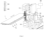
- FIG. 2 is a perspective view illustrating the facility for measuring the sealing gap for the secondary battery according to a first embodiment of the present invention
- FIG. 3 is a partial enlarged view of FIG. 2
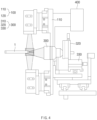
- FIG. 4 is a front view of FIG. 2
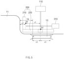
- FIG. 5 is a view for explaining a sealing gap measurement state using the facility for measuring the sealing gap for the secondary battery according to the first embodiment of the present invention
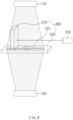
- FIG. 6 is a perspective view illustrating an origin point structure of the facility for measuring the sealing gap for the secondary battery according to the first embodiment of the present invention
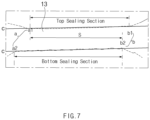
- FIG. 7 is a view for explaining a state of measuring a sealing width of the facility for measuring the sealing gap for the secondary battery according to the first embodiment of the present invention.
- the facility for measuring the sealing gap for the secondary battery according to the first embodiment of the present invention is configured to measure the sealing gap disposed between the electrode assembly accommodation part and the sealing part of the pouch.
- the facility for measuring the sealing gap for the secondary battery according to the first embodiment of the present invention may include a first measurement device 100, an origin point structure 200, a second measurement device 300, and a controller 400.
- the first measurement device 100 is configured to acquire an inner start point and an outer end point of the sealing part.
- the first measurement device 100 acquires a sealing width S through the inner start point a and the outer end point b of the sealing part 13 provided in the pouch.
- a first reference origin point O1 is set within the sealing width S.
- the sealing of the pouch is performed from the electrode assembly accommodation part toward the gas pocket part.
- a point at which the sealing starts is referred to as the inner start point a, and a point at which the sealing is ended is referred to as the outer end point b.
- the first measurement device 100 include a first displacement sensor 110 and a second displacement sensor 120
- the first displacement sensor 110 and the second displacement sensor 120 are provided to correspond to both sides (upper and lower portions of the pouch when viewed in FIG. 1 ) with respect to the pouch 10, and beam is irradiated onto a surface of the pouch to measure each of the inner start point a and the outer end point b of the sealing part 13.
- the first displacement sensor 110 and the second displacement sensor 120 acquire the sealing width S through a distance between the inner start point a and the outer end point b.
- the first displacement sensor 110 and the second displacement sensor 120 generate a virtual horizontal line c to match sealing surfaces that are respectively formed on both surfaces of the pouch 10, and a point deviating from the virtual horizontal line c with respect to the virtual horizontal line c is regarded as an area except for the sealing area to designate the inner start point a and the outer end point b.
- the sealing width S may be calculated by measuring a distance between the inner start point a and the outer end point b.
- Each of the first displacement sensor 110 and the second displacement sensor 120 may be a line laser sensor.
- the line laser sensor refers to a device such as a scanner or facsimile that reads information such as characters and figures existing on a surface of a paper or object.
- the first measurement device 100 may further include a first vertical moving member 130. That is, the first vertical moving member 130 moves the first and second displacement sensors 110 and 120 toward both the surfaces of the pouch (top and bottom surfaces of the pouch when viewed in FIG. 2 ) or move the first and second displacement sensors 110 and 120 to be away from both the surfaces of the pouch.
- the first vertical moving member 130 may simultaneously move the first and second displacement sensors 120 in a direction toward the pouch or in an opposite direction thereof, and as a result, the distance may be adjusted so that the beam of the first and second displacement sensors 110 and 120 is accurately irradiated to the surface of the pouch.
- the first measurement device 100 may further include a first full-width moving member 140. That is, the first full width moving member 140 moves the first and second displacement sensors 110 and 120 in the full-width direction of the pouch (a left and right direction of the pouch when viewed in FIG. 2 ) to locate the first and second displacement sensors 110 and 120 on the sealing part of the pouch.
- the first and second displacement sensors 110 and 120 may be accurately disposed on the sealing part of the pouch, and as a result, the sealing width of the sealing part may be accurately measured.
- the origin point structure 200 provides a vertical reference surface corresponding to a point that is moved by a predetermined first distance X1 from a first reference origin point O1 disposed between the inner start point and the outer end point in the direction of the electrode assembly accommodation part.
- the origin point structure 200 is configured to set a second reference origin point O2 for measuring the sealing gap, and a vertical reference surface 210 disposed at a point moved by the first distance X1 from the first reference origin point O1 in the direction of the electrode assembly accommodating part is provided.
- the origin point structure 200 moves the vertical reference surface 210 horizontally from the first reference origin point O1 toward the electrode assembly accommodation part by the first distance X1 and then set the point as the second reference origin point O2.
- the vertical reference surface 210 sets the second reference origin point O2 at a point that is not disposed within the sealing width S. This is done for preventing a measurement error from occurring due to the vertical reference surface when measuring the sealing width through the first and second displacement sensors 110 and 120.
- the origin point structure 200 may further include a horizontal reference surface 220 for locating the first and second displacement sensors 110 and 120 and the third displacement sensor 310 on the same vertical surface.
- the horizontal reference surface 220 extends long from a lower end of the vertical reference surface 210 in the direction of the sealing width, and a through-hole 221 through which the beam irradiated from the first displacement sensor 110 passes is defined.
- the beam of the third displacement sensor 310 is irradiated to the vertical reference surface 210
- the beam of the first displacement sensor 110 is irradiated to the through-hole of the horizontal reference surface 220.
- the first and second displacement sensors 110 and 120 and the third displacement sensor 310 may be adjusted to be disposed on the same line, and as a result, an occurrence of errors in measuring the sealing width may be minimized.
- the second measurement device 300 is configured to acquire a second distance X2 from the vertical reference surface to the electrode assembly accommodation part.
- the second measurement device 300 includes a third displacement sensor 310.
- the third displacement sensor 310 irradiates beam toward the vertical reference surface 210 to set a point, at which the vertical reference surface 210 is disposed, as the second reference origin O2, and beam is irradiated to the electrode assembly accommodating part 11 to pass through the second reference origin point O2, thereby acquiring the second distance X2 from the second reference origin O2 to the electrode assembly accommodating part 11.
- the second measurement device 300 may further include a second vertical moving member 320.
- the second vertical moving member 320 allows the third displacement sensor 310 to ascend or descend so that the third displacement sensor 310 irradiates beam toward the vertical reference surface 210 of the origin point structure 200.
- a position of the third displacement sensor 310 may be accurately adjusted so that the beam of the third displacement sensor 310 is irradiated to the vertical reference surface 210 of the origin point structure 200.
- the second measurement device 300 may further include a second full-width moving member 250.
- the second full-width moving member 250 may move the third displacement sensor 310 forward or backward toward the pouch in order to adjust a distance between the third displacement sensors 310 based on the vertical reference surface 210.
- the distance between the vertical reference surface 210 and the third displacement sensor may be adjusted.
- the controller 400 is configured to acquire the sealing gap based on the first distance X1, the second distance X2, and the third distance X3 from the inner start point to the first reference origin point 01.
- the controller 400 sets the first reference origin point O1 between the inner start point a and the outer end point b and acquires the third distance X3 from the inner start point a to the first reference origin point O1.
- the sealing gap may be acquired based on the first distance X1, the second distance X2, and the third distance X3.
- the controller 400 may acquire a value acquired by subtracting the third distance X3 from the sum of the first distance X1 and the second distance X2 as the sealing gap 14.
- the controller 400 may set the first reference origin point O1 at a central point of the sealing width S.
- the distance between the inner start point and the first reference origin point and the distance between the outer end point and the first reference origin point are symmetrical to each other to improve efficiency of calculation.
- the controller 400 sets overlapping points between the inner start point a and the outer end point b of the sealing part 13, which are respectively measured by the first displacement sensor 110 and the second displacement sensor 120, as the inner start point a and the outer end point b of the sealing part 13.
- the controller 400 set overlapping points between the inner start point and the outer end point of the sealing part, which are measured by the first displacement sensor 110 and the second displacement sensor 120 as the inner start point and the outer end point of the sealing part.
- the controller 400 sets the inner start point a1 of the overlapping top sealing surface of the inner start point a1 of the upper sealing surface and the inner starting point a2 of the lower sealing surface as the inner starting point of the sealing unit and sets the outer end point b2 of the overlapping lower sealing surface of the outer end point b1 of the upper sealing surface and the outer end point b2 of the lower sealing surface as the outer end point of the sealing part.
- accuracy in measurement with respect to the sealing width S may be improved.
- the controller 400 acquires a thickness of the sealing width based on the distance between the sealing width measured by the first displacement sensor 110 and the sealing width measured by the second displacement sensor 120. Thus, the thickness of the sealing width may be accurately measured without an additional facility.
- the controller 400 may determine that the sealing gap 14 measured by the second measurement device 300 is less or greater than the previously input sealing gap as defective. Thus, defects in the sealing gap disposed in the pouch may be accurately measured and inspected.
- the input sealing gap may be set according to a size of the pouch and a capacity of the electrode assembly.
- the facility for measuring the sealing gap for the secondary battery according to the first embodiment of the present invention may include a first measurement device 100, an origin point structure 200, a second measurement device 300, and a controller 400 to accurately measure the sealing gap provided in the pouch.
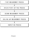
- FIG. 8 is a flowchart illustrating a method for measuring a sealing gap for a secondary battery according to the first embodiment of the present invention.
- the method for measuring the sealing gap for the secondary battery according to the first embodiment of the present invention is configured to measure a sealing gap disposed between an electrode assembly accommodation part and a sealing part of a pouch.
- the method for measuring the sealing gap for the secondary battery according to the first embodiment of the present invention includes a first measurement process, an origin point setting process, a second measurement process, and a sealing gap measurement process.
- a first measurement device 100 In the first measurement process, a first measurement device 100 is used, and the first measurement device 100 includes a first displacement sensor 110 and a second displacement sensor 120.
- a sealing width S is acquired through an inner start point a and an outer end point b of a sealing part 13 provided in the pouch.
- a first reference origin point O1 is set within the sealing width.
- the first measurement step includes a first process of measuring an inner start point and an outer end point of the sealing part by irradiating beam on one surface of the pouch, and a second process of measuring an inner start point and an outer end point of the sealing part by irradiating beam on the other surface of the pouch.
- the inner start point and the outer end point of the sealing part formed on both sides of the pouch are measured through the first displacement sensor 110 and the second displacement sensor 120, which are provided on both surfaces of the pouch, respectively.
- the first displacement sensor 110 measures the inner start point a1 and the outer end point b1 of the upper sealing surface formed on the top surface of the pouch
- the second displacement sensor 120 measures the inner start point a2 and the outer end point b2 of the lower sealing surface formed on the bottom surface of the pouch.
- the sealing width S is acquired by measuring the distance between the inner start point and the outer end point of the sealing surface measured by the first and second displacement sensors 110 and 120.
- a first reference origin point O1 is set within the sealing width S.
- the first reference origin point may be set at a center point of the sealing width.
- the points at which the inner start point and the outer end point of the sealing part provided on both the surfaces of the pouch overlap each other are set as the inner start point and outer end point of the sealing part, respectively.
- the first measurement process further includes a third process of setting the points at which the inner start point and the outer end point of the sealing part overlap each other as the inner start point and the outer end point of the sealing part, respectively.
- the inner start point a1 of the upper sealing surface of the inner start point a1 of the upper sealing surface and the inner start point a2 of the lower sealing surface is set, and the outer end point b2 of the lower sealing surface of the outer end point b1 of the upper sealing surface and the outer end point b2 of the lower sealing surface is set.
- the first measurement process further includes a process of acquiring a thickness of the sealing width based on the distance between the sealing width measured in the first process and the sealing width measured in the second process. That is, the thickness of the sealing width may be acquired based on the distance between the sealing width measured by the first displacement sensor 110 and the sealing width measured by the second displacement sensor 120.
- a third distance X3 between the inner start point a and the first reference origin point O1 is acquired.
- the origin point setting process uses an origin point structure 200, and the origin point structure 200 includes a vertical reference surface 210 and a horizontal reference surface 220.
- the vertical reference surface 210 corresponding to a point moved by a predetermined first distance X1 in a direction of the electrode assembly accommodation part from the first reference origin point O1 disposed between the inner start point a and the outer end point b is set.
- the first and second displacement sensors 110 and 120 and the third displacement sensor 310 to be described later may be disposed on the same vertical surface.
- the horizontal reference surface 220 extends in the sealing width direction from the lower end of the vertical reference surface 210.
- the beam of the third displacement sensor 310 is irradiated to the vertical reference surface 210, and the beam of the first displacement sensor 110 is irradiated to the through-hole of the horizontal reference surface 220.
- the first and second displacement sensors 120 and the third displacement sensor 310 may be adjusted to be disposed on the same line, and as a result, an occurrence of errors in measuring the sealing width may be minimized.
- the second measurement process uses a second measurement device 300, and the second measurement device 300 includes a third displacement sensor 310.
- beam is irradiated toward the vertical reference surface 210 to set a point at which the vertical reference surface 210 is disposed as the second reference origin point O2, and then, beam is irradiated to the electrode assembly accommodating part to pass through the second reference origin point O2, thereby acquiring the second distance X2 from the second reference origin O2 to the electrode assembly accommodating part 11.
- the second reference origin point O2 is set so as not to be disposed between the inner start point and outer end point of the sealing part.
- the sealing gap is acquired based on the first distance X1, the second distance X2, and the third distance X3 from the inner start point to the first reference origin point O1.
- a value acquired by subtracting the third distance X3 from the sum of the first distance X1 and the second distance X2 may be acquired as the sealing gap.
- the sealing gap measurement process may further include an inspection process of determining whether the measured sealing gap is defective.
- the inspection process if the measured sealing gap is less or greater than a previously input sealing gap, it is determined as a defect.
- the sealing gap may be accurately measured, and whether the sealing gap is defective may be accurately inspected.
- a facility 1000 for measuring a sealing gap for a secondary battery may include a first measurement device, an origin point structure, a second measurement device, and a controller.
- the first measurement device, the origin point structure, the second measurement device, and the controller have the same configurations as the first measurement device, the origin point structure, the second measurement device, and the controller of the facility for measuring the sealing gap for the secondary battery according to the first embodiment, and thus, redundant descriptions thereof are omitted.
- the facility 1000 for measuring the sealing gap for the secondary battery according to the second embodiment of the present invention includes a jig device 410 on which a pouch is disposed and a guide device 500 that slidably moves the first and second measurement devices 100 and 300 in a full-length direction of a pouch.
- the jig device 410 fixes the pouch without movement while disposing the pouch thereon.
- the guide device 500 moves the jig device 410 in the full-length direction of the pouch to inspect whether the sealing gap formed in the pouch is defective on the whole.
- the guide device 500 includes a guide rail 510 formed in the full-length direction of the pouch, and a guide member 520 movably coupled to the guide rail 510 to move the jig device along the guide rail.
- the facility for measuring the sealing gap for the secondary battery according to the second embodiment of the present invention may measure the entire sealing gap formed in the full-length direction of the pouch to inspect whether the sealing gap is defective on the whole.
Landscapes
- Physics & Mathematics (AREA)
- General Physics & Mathematics (AREA)
- Chemical & Material Sciences (AREA)
- Chemical Kinetics & Catalysis (AREA)
- Electrochemistry (AREA)
- General Chemical & Material Sciences (AREA)
- Engineering & Computer Science (AREA)
- Manufacturing & Machinery (AREA)
- Secondary Cells (AREA)
- Length Measuring Devices By Optical Means (AREA)
Abstract
Description
- The present application claims the benefit of the priority of
Korean Patent Application Nos. 10-2022-0035013, filed on March 21, 2022 10-2023-0036787, filed on March 21, 2023 - The present invention relates to a facility and method for measuring a sealing gap for a secondary battery, in which a sealing gap disposed between an electrode assembly accommodation part and a sealing part of a pouch is capable of being accurately measured.
- In general, secondary batteries refer to chargeable and dischargeable, unlike primary batteries that are not chargeable. The secondary batteries are being widely used for mobile phones, notebook computers, and camcorders, electric vehicles, and the like.
- The secondary batteries are classified into a can type secondary battery, in which an electrode assembly is embedded in a metal can, a pouch type secondary battery in which an electrode assembly is embedded in a pouch, and a button type secondary battery having a coin shape.
- Also, a pouch type secondary battery includes an electrode assembly and a pouch accommodating the electrode assembly. That is, the electrode assembly has a structure in which a positive electrode and a negative electrode are alternately disposed with a separator therebetween. The pouch includes an accommodation part accommodating the electrode assembly and a sealing part sealing the accommodation part while being formed on an edge of the accommodation part.
- In the secondary battery, three of four edges formed on the pouch are sealed first in an assembly process to form a sealing part, and a remaining one edge formed on the pouch is sealed in a degassing process to form a sealing part.
- Here, the sealing part formed on the pouch has to be formed in consideration of a full width of the electrode assembly, insulation failure, and sealing failure. The full width of the electrode assembly may include a sealing gap disposed between the accommodation part and the sealing part.
- The sealing gap requires a certain width to ensure safety. That is, the sealing gap has a width set according to a thickness of the accommodation part. In particular, the sealing gap may have different values in the assembly process and the degassing process. That is, in the assembling process, the electrode assembly, an electrolyte, and a gas may be filled in the accommodation part, and in the degassing process, the gas inside the accommodation part may be discharged to cause a difference in sealing gap.
- Here, the difference in sealing gap in the assembly process and the degassing process may cause defects in a process of folding the sealing part, and thus, it is necessary to accurately measure the sealing gap in the degassing process.
- In the related art, the sealing gap disposed between the accommodation part and the sealing part of the pouch was measured using a steel ruler. However, the steel ruler has a problem in that a measured value varies depending on the number of measurements or each operator, and thus, it is difficult to accurately measure the sealing gap.
- An object of the present invention is to provide a facility and method for measuring a sealing gap for a secondary battery, in which a sealing gap disposed between an electrode assembly accommodation part and a sealing part of a pouch is capable of being accurately measured.
- The present invention provides a facility for measuring a sealing gap for a secondary battery, which measures a sealing gap disposed between an electrode assembly accommodation part and a sealing part of a pouch, and the facility includes: a first measurement device configured to acquire an inner start point and an outer end point of the sealing part; an origin point structure having a vertical reference surface corresponding to a point moved by a predetermined first distance (X1) in a direction of the electrode assembly accommodation part from a first reference origin point (O1) disposed between the inner start point and the outer end point; a second measurement device configured to acquire a second distance (X2) from the vertical reference surface to the electrode assembly accommodation part; and a controller configured to acquire the sealing gap based on the first distance (X1), the second distance (X2), and a third distance (X3) from the inner start point to the first reference origin point (O1).
- The controller may be configured to set the first reference origin point between the inner start point to the outer end point and acquire the third distance (X3) from the inner start point to the first reference origin point (O1).
- The first measurement device may include: a first displacement sensor configured to irradiate beam to one surface of the pouch so as to measure the inner start point and the outer end point of the sealing part; and a second displacement sensor configured to irradiate beam to the other surface of the pouch so as to measure the inner start point and the outer end point of the sealing part.
- If the inner start point and the outer end point of the sealing part, which are measured by the first displacement sensor and the second displacement sensor do not match, the controller may be configured to set points at which the inner start point and the outer end point, which are respectively measured by the first displacement sensor and the second displacement sensor, overlap each other, as the inner start point and the outer end point of the sealing part.
- A thickness of a sealing width may be acquired based on a distance between a sealing width measured by the first displacement sensor and a sealing width measured by the second displacement sensor.
- The second measurement device may be configured to irradiate beam toward the vertical reference surface so as to set a point at which the vertical reference surface is disposed as a second reference origin point (O2) and irradiate beam to the electrode assembly accommodation part so that the beam passes through the second reference origin point (O2) so as to acquire the second distance (X2) from the second reference origin point (O2) to the electrode assembly accommodation part.
- The second measurement device may include a third displacement sensor configured to irradiate beam toward the vertical reference surface so as to set a point at which the vertical reference surface is disposed as the second reference origin point (O2).
- The controller may be configured to acquire a value obtained by subtracting the third distance (X3) from the sum of the first distance (X1) and the second distance (X2) as the sealing gap.
- The second reference origin point (O2) may be set so as not to be disposed within the sealing width.
- The origin point structure may further include a horizontal reference surface extending from the vertical reference surface in the direction of the sealing width and having a through-hole through which the beam irradiated from the first displacement sensor passes.
- The controller may be configured to determine that the sealing gap measured by the second measurement device is defective when the sealing gap is less or greater than a previously input sealing gap.
- A method for measuring a sealing gap for a secondary battery, in which a sealing gap disposed between an electrode assembly accommodation part and a sealing part of a pouch is measured according to the present invention includes: a first measurement process of acquiring an inner start point and an outer end point of the sealing part; an origin point setting process of setting a vertical reference surface corresponding to a point moved by a predetermined first distance (X1) in a direction of the electrode assembly accommodation part from a first reference origin point disposed between the inner start point and the outer end point; a second measurement process of acquiring a second distance (X2) from the vertical reference surface to the electrode assembly accommodation part; and a sealing gap measurement process of acquiring the sealing gap based on the first distance (X1), the second distance (X2), and a third distance (X3) from the inner start point to the first reference origin point (O1).
- In the first measurement process, the first reference origin point between the inner start point to the outer end point is set, and the third distance (X3) from the inner start point to the first reference origin point (O1) may be acquired.
- The first measurement process may further include: a first process of irradiating beam to one surface of the pouch to measure the inner start point and the outer end point of the sealing part; a second process of irradiating beam to the other surface of the pouch to measure the inner start point and the outer end point of the sealing part; and a third process of setting points at which the inner start point and the outer end point of the sealing part overlap each other as the inner start point and the outer end point of the sealing part if the inner start point and the outer end point of the sealing part, which are measured in the first process and the second process, do not match.
- The first measurement process may further include a process of acquiring a thickness of a sealing width based on a distance between a sealing width measured in the first process and a sealing width measured in the second process.
- In the second measurement process, beam may be irradiated toward the vertical reference surface to set a point at which the vertical reference surface is disposed as a second reference origin point (O2), and beam may be irradiated to the electrode assembly accommodation part so that the beam passes through the second reference origin point (O2) to acquire the second distance (X2) from the second reference origin point (O2) to the electrode assembly accommodation part.
- In the second measurement process, the second reference origin point (O2) may be set so as not to be disposed between the inner start point and the outer end point of the sealing part.
- In the sealing gap measurement process, a value obtained by subtracting the third distance (X3) from the sum of the first distance (X1) and the second distance (X2) may be acquired as the sealing gap.
- The method may further include an inspection process of determining whether the measured sealing gap is defective after the sealing gap measurement process is completed, wherein, in the inspection process, when the measured sealing gap is smaller or larger than the previously input sealing gap, it may be determined that the sealing gap is defective.
- The facility for measuring the sealing gap for the secondary battery according to the present invention may include the first measurement device and the second measurement device to accurately measure the sealing gap disposed between the electrode assembly accommodation part and the sealing part of the pouch, thereby accurately determining whether the sealing gap is defective.
-
-
FIG. 1 is a cross-sectional view of a secondary battery to the present invention. -
FIG. 2 is a perspective view illustrating a facility for measuring a sealing gap for a secondary battery according to a first embodiment of the present invention. -
FIG. 3 is a partial enlarged view ofFIG. 2 . -
FIG. 4 is a front view ofFIG. 2 . -
FIG. 5 is a view for explaining a sealing gap measurement state using the facility for measuring the sealing gap for the secondary battery according to the first embodiment of the present invention. -
FIG. 6 is a perspective view illustrating an origin point structure of the facility for measuring the sealing gap for the secondary battery according to the first embodiment of the present invention. -
FIG. 7 is a view for explaining a state of measuring a sealing width of the facility for measuring the sealing gap for the secondary battery according to the first embodiment of the present invention. -
FIG. 8 is a flowchart illustrating a method for measuring a sealing gap for a secondary battery according to the first embodiment of the present invention. -
FIG. 9 is a schematic view of a first measurement process. -
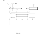
FIG. 10 is a schematic view of an origin setting process and a second measurement process. -
FIG. 11 is a schematic view of a sealing gap measurement process. -
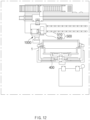
FIG. 12 is a plan view illustrating a facility for measuring a sealing gap for a secondary battery according to a second embodiment of the present invention. - Hereinafter, embodiments of the present invention will be described in detail with reference to the accompanying drawings in such a manner that the technical idea of the present invention may easily be carried out by a person with ordinary skill in the art to which the invention pertains. The present invention may, however, be embodied in different forms and should not be construed as limited to the embodiments set forth herein. In the drawings, anything unnecessary for describing the present invention will be omitted for clarity, and also like reference numerals in the drawings denote like elements.
-
FIG. 1 is a perspective view of a secondary battery to the present invention. - Referring to
FIG. 1 , asecondary battery 1 of the present invention includes an electrode assembly, an electrolyte (not shown), and apouch 10 accommodating the electrode assembly and the electrolyte. - The electrode assembly has a structure in which a plurality of electrodes and a plurality of separators are alternately disposed. The plurality of electrodes may be positive and negative electrodes. Here, electrode tabs are provided on the plurality of electrodes, and electrode leads are coupled to the electrode tabs.
- The
pouch 10 includes an electrodeassembly accommodation part 11 accommodating an electrode assembly, agas pocket part 12 collecting a gas generated in the electrodeassembly accommodation part 11, and a sealingpart 13 sealing the electrodeassembly accommodation part 11 and thegas pocket part 12, and the sealingpart 13 includes a sealing surface sealing an edge of the electrodeassembly accommodation part 11 and thegas pocket part 12, and a re-sealing surface sealing a gap between the electrode assembly accommodation part and the gas pocket part. - A sealing
gap 14 is provided in a full-width direction of the pouch 10 (left and right direction of the pouch as viewed inFIG. 1 ) to prevent defects from occurring when sealing the pouch, and the sealinggap 14 is disposed between the electrodeassembly accommodation part 11 and the sealingpart 13. That is, the sealinggap 14 may be an extra space that is not sealed. - The sealing
gap 14 requires a certain width to ensure safety, and thus, it is necessary to measure whether the sealing gap secured in the pouch is accurately secured. Here, a facility for measuring the sealing gap for the secondary battery according to a first embodiment of the present invention may be used. - Hereinafter, the facility for measuring the sealing gap for the secondary battery according to the first embodiment of the present invention will be described in detail with reference to the accompanying drawings.
-
FIG. 2 is a perspective view illustrating the facility for measuring the sealing gap for the secondary battery according to a first embodiment of the present invention,FIG. 3 is a partial enlarged view ofFIG. 2 ,FIG. 4 is a front view ofFIG. 2 ,FIG. 5 is a view for explaining a sealing gap measurement state using the facility for measuring the sealing gap for the secondary battery according to the first embodiment of the present invention,FIG. 6 is a perspective view illustrating an origin point structure of the facility for measuring the sealing gap for the secondary battery according to the first embodiment of the present invention, andFIG. 7 is a view for explaining a state of measuring a sealing width of the facility for measuring the sealing gap for the secondary battery according to the first embodiment of the present invention.
the facility for measuring the sealing gap for the secondary battery according to the first embodiment of the present invention is configured to measure the sealing gap disposed between the electrode assembly accommodation part and the sealing part of the pouch. - That is, as illustrated in
FIGS. 1 to 4 , the facility for measuring the sealing gap for the secondary battery according to the first embodiment of the present invention may include afirst measurement device 100, anorigin point structure 200, asecond measurement device 300, and acontroller 400. - The
first measurement device 100 is configured to acquire an inner start point and an outer end point of the sealing part. - That is, the
first measurement device 100 acquires a sealing width S through the inner start point a and the outer end point b of the sealingpart 13 provided in the pouch. In addition, a first reference origin point O1 is set within the sealing width S. - The sealing of the pouch is performed from the electrode assembly accommodation part toward the gas pocket part. A point at which the sealing starts is referred to as the inner start point a, and a point at which the sealing is ended is referred to as the outer end point b.
- For example, the
first measurement device 100 include afirst displacement sensor 110 and asecond displacement sensor 120, thefirst displacement sensor 110 and thesecond displacement sensor 120 are provided to correspond to both sides (upper and lower portions of the pouch when viewed inFIG. 1 ) with respect to thepouch 10, and beam is irradiated onto a surface of the pouch to measure each of the inner start point a and the outer end point b of the sealingpart 13. Thus, thefirst displacement sensor 110 and thesecond displacement sensor 120 acquire the sealing width S through a distance between the inner start point a and the outer end point b. - Referring to
FIG. 7 , thefirst displacement sensor 110 and thesecond displacement sensor 120 generate a virtual horizontal line c to match sealing surfaces that are respectively formed on both surfaces of thepouch 10, and a point deviating from the virtual horizontal line c with respect to the virtual horizontal line c is regarded as an area except for the sealing area to designate the inner start point a and the outer end point b. In addition, the sealing width S may be calculated by measuring a distance between the inner start point a and the outer end point b. - Each of the
first displacement sensor 110 and thesecond displacement sensor 120 may be a line laser sensor. The line laser sensor refers to a device such as a scanner or facsimile that reads information such as characters and figures existing on a surface of a paper or object. - The
first measurement device 100 may further include a first vertical movingmember 130. That is, the first vertical movingmember 130 moves the first andsecond displacement sensors FIG. 2 ) or move the first andsecond displacement sensors member 130 may simultaneously move the first andsecond displacement sensors 120 in a direction toward the pouch or in an opposite direction thereof, and as a result, the distance may be adjusted so that the beam of the first andsecond displacement sensors - In addition, the
first measurement device 100 may further include a first full-width moving member 140. That is, the first fullwidth moving member 140 moves the first andsecond displacement sensors FIG. 2 ) to locate the first andsecond displacement sensors second displacement sensors - The
origin point structure 200 provides a vertical reference surface corresponding to a point that is moved by a predetermined first distance X1 from a first reference origin point O1 disposed between the inner start point and the outer end point in the direction of the electrode assembly accommodation part. - That is, the
origin point structure 200 is configured to set a second reference origin point O2 for measuring the sealing gap, and avertical reference surface 210 disposed at a point moved by the first distance X1 from the first reference origin point O1 in the direction of the electrode assembly accommodating part is provided. In addition, theorigin point structure 200 moves thevertical reference surface 210 horizontally from the first reference origin point O1 toward the electrode assembly accommodation part by the first distance X1 and then set the point as the second reference origin point O2. - Here, the
vertical reference surface 210 sets the second reference origin point O2 at a point that is not disposed within the sealing width S. This is done for preventing a measurement error from occurring due to the vertical reference surface when measuring the sealing width through the first andsecond displacement sensors - Particularly, the
origin point structure 200 may further include ahorizontal reference surface 220 for locating the first andsecond displacement sensors third displacement sensor 310 on the same vertical surface. - That is, the
horizontal reference surface 220 extends long from a lower end of thevertical reference surface 210 in the direction of the sealing width, and a through-hole 221 through which the beam irradiated from thefirst displacement sensor 110 passes is defined. Thus, in theorigin point structure 200, the beam of thethird displacement sensor 310 is irradiated to thevertical reference surface 210, and the beam of thefirst displacement sensor 110 is irradiated to the through-hole of thehorizontal reference surface 220. Thus, the first andsecond displacement sensors third displacement sensor 310 may be adjusted to be disposed on the same line, and as a result, an occurrence of errors in measuring the sealing width may be minimized. - The
second measurement device 300 is configured to acquire a second distance X2 from the vertical reference surface to the electrode assembly accommodation part. - That is, referring to
FIG. 5 , thesecond measurement device 300 includes athird displacement sensor 310. Thethird displacement sensor 310 irradiates beam toward thevertical reference surface 210 to set a point, at which thevertical reference surface 210 is disposed, as the second reference origin O2, and beam is irradiated to the electrodeassembly accommodating part 11 to pass through the second reference origin point O2, thereby acquiring the second distance X2 from the second reference origin O2 to the electrodeassembly accommodating part 11. - The
second measurement device 300 may further include a second vertical movingmember 320. The second vertical movingmember 320 allows thethird displacement sensor 310 to ascend or descend so that thethird displacement sensor 310 irradiates beam toward thevertical reference surface 210 of theorigin point structure 200. Thus, a position of thethird displacement sensor 310 may be accurately adjusted so that the beam of thethird displacement sensor 310 is irradiated to thevertical reference surface 210 of theorigin point structure 200. - In addition, the
second measurement device 300 may further include a second full-width moving member 250. The second full-width moving member 250 may move thethird displacement sensor 310 forward or backward toward the pouch in order to adjust a distance between thethird displacement sensors 310 based on thevertical reference surface 210. Thus, the distance between thevertical reference surface 210 and the third displacement sensor may be adjusted. - The
controller 400 is configured to acquire the sealing gap based on the first distance X1, the second distance X2, and the third distance X3 from the inner start point to the firstreference origin point 01. - That is, the
controller 400 sets the first reference origin point O1 between the inner start point a and the outer end point b and acquires the third distance X3 from the inner start point a to the first reference origin point O1. The sealing gap may be acquired based on the first distance X1, the second distance X2, and the third distance X3. - For example, the
controller 400 may acquire a value acquired by subtracting the third distance X3 from the sum of the first distance X1 and the second distance X2 as the sealinggap 14. - The
controller 400 may set the first reference origin point O1 at a central point of the sealing width S. In this case, the distance between the inner start point and the first reference origin point and the distance between the outer end point and the first reference origin point are symmetrical to each other to improve efficiency of calculation. - When the inner start point a and outer end point b of the sealing
part 13 measured by thefirst displacement sensor 110 and thesecond displacement sensor 120 do not match each other, thecontroller 400 sets overlapping points between the inner start point a and the outer end point b of the sealingpart 13, which are respectively measured by thefirst displacement sensor 110 and thesecond displacement sensor 120, as the inner start point a and the outer end point b of the sealingpart 13. - That is, when an inner start point a1 and an outer end point b2, which are measured by the
first displacement sensor 110 match with an inner start point a2 and an outer end point b2, which are measured by thesecond displacement sensor 120, thecontroller 400 set overlapping points between the inner start point and the outer end point of the sealing part, which are measured by thefirst displacement sensor 110 and thesecond displacement sensor 120 as the inner start point and the outer end point of the sealing part. - In other words, referring to
FIG. 5 , thecontroller 400 sets the inner start point a1 of the overlapping top sealing surface of the inner start point a1 of the upper sealing surface and the inner starting point a2 of the lower sealing surface as the inner starting point of the sealing unit and sets the outer end point b2 of the overlapping lower sealing surface of the outer end point b1 of the upper sealing surface and the outer end point b2 of the lower sealing surface as the outer end point of the sealing part. Thus, accuracy in measurement with respect to the sealing width S may be improved. - The
controller 400 acquires a thickness of the sealing width based on the distance between the sealing width measured by thefirst displacement sensor 110 and the sealing width measured by thesecond displacement sensor 120. Thus, the thickness of the sealing width may be accurately measured without an additional facility. - The
controller 400 may determine that the sealinggap 14 measured by thesecond measurement device 300 is less or greater than the previously input sealing gap as defective. Thus, defects in the sealing gap disposed in the pouch may be accurately measured and inspected. The input sealing gap may be set according to a size of the pouch and a capacity of the electrode assembly. - Therefore, the facility for measuring the sealing gap for the secondary battery according to the first embodiment of the present invention may include a
first measurement device 100, anorigin point structure 200, asecond measurement device 300, and acontroller 400 to accurately measure the sealing gap provided in the pouch. - Hereinafter, a method for measuring a sealing gap for a secondary battery according to the first embodiment of the present invention will be described.
-
FIG. 8 is a flowchart illustrating a method for measuring a sealing gap for a secondary battery according to the first embodiment of the present invention. - As illustrated in
FIG. 8 , the method for measuring the sealing gap for the secondary battery according to the first embodiment of the present invention is configured to measure a sealing gap disposed between an electrode assembly accommodation part and a sealing part of a pouch. - That is, the method for measuring the sealing gap for the secondary battery according to the first embodiment of the present invention includes a first measurement process, an origin point setting process, a second measurement process, and a sealing gap measurement process.
- In the first measurement process, a
first measurement device 100 is used, and thefirst measurement device 100 includes afirst displacement sensor 110 and asecond displacement sensor 120. - That is, in the first measurement process, as illustrated in
FIG. 9 , a sealing width S is acquired through an inner start point a and an outer end point b of a sealingpart 13 provided in the pouch. Next, a first reference origin point O1 is set within the sealing width. - In other words, the first measurement step includes a first process of measuring an inner start point and an outer end point of the sealing part by irradiating beam on one surface of the pouch, and a second process of measuring an inner start point and an outer end point of the sealing part by irradiating beam on the other surface of the pouch.
- In more detail, referring to
FIG. 7 , in the first measurement process, the inner start point and the outer end point of the sealing part formed on both sides of the pouch are measured through thefirst displacement sensor 110 and thesecond displacement sensor 120, which are provided on both surfaces of the pouch, respectively. For example, thefirst displacement sensor 110 measures the inner start point a1 and the outer end point b1 of the upper sealing surface formed on the top surface of the pouch, and thesecond displacement sensor 120 measures the inner start point a2 and the outer end point b2 of the lower sealing surface formed on the bottom surface of the pouch. In addition, the sealing width S is acquired by measuring the distance between the inner start point and the outer end point of the sealing surface measured by the first andsecond displacement sensors - Here, the first reference origin point may be set at a center point of the sealing width.
- In the first measurement process, if the inner start points and the outer end points of the sealing part provided on both the surfaces of the pouch do not match, the points at which the inner start point and the outer end point of the sealing part provided on both the surfaces of the pouch overlap each other are set as the inner start point and outer end point of the sealing part, respectively.
- That is, if the inner start points and the outer end points of the sealing part measured in the first process and the second process do not match, the first measurement process further includes a third process of setting the points at which the inner start point and the outer end point of the sealing part overlap each other as the inner start point and the outer end point of the sealing part, respectively.
- For example, in the first measurement process, referring to
FIG. 7 , the inner start point a1 of the upper sealing surface of the inner start point a1 of the upper sealing surface and the inner start point a2 of the lower sealing surface is set, and the outer end point b2 of the lower sealing surface of the outer end point b1 of the upper sealing surface and the outer end point b2 of the lower sealing surface is set. - The first measurement process further includes a process of acquiring a thickness of the sealing width based on the distance between the sealing width measured in the first process and the sealing width measured in the second process. That is, the thickness of the sealing width may be acquired based on the distance between the sealing width measured by the
first displacement sensor 110 and the sealing width measured by thesecond displacement sensor 120. - In the first measurement process, after setting the first reference origin point O1 between the inner start point a and the outer end point b, a third distance X3 between the inner start point a and the first reference origin point O1 is acquired.
- The origin point setting process uses an
origin point structure 200, and theorigin point structure 200 includes avertical reference surface 210 and ahorizontal reference surface 220. - That is, in the origin point setting process, as illustrated in
FIG. 10 , thevertical reference surface 210 corresponding to a point moved by a predetermined first distance X1 in a direction of the electrode assembly accommodation part from the first reference origin point O1 disposed between the inner start point a and the outer end point b is set. - In the origin point setting process, beam irradiated from the
first displacement sensor 110 passes through a through-hole 221 formed in thehorizontal reference surface 220 of theorigin point structure 200, and thus, the first andsecond displacement sensors third displacement sensor 310 to be described later may be disposed on the same vertical surface. Here, thehorizontal reference surface 220 extends in the sealing width direction from the lower end of thevertical reference surface 210. Thus, in theorigin point structure 200, the beam of thethird displacement sensor 310 is irradiated to thevertical reference surface 210, and the beam of thefirst displacement sensor 110 is irradiated to the through-hole of thehorizontal reference surface 220. Thus, the first andsecond displacement sensors 120 and thethird displacement sensor 310 may be adjusted to be disposed on the same line, and as a result, an occurrence of errors in measuring the sealing width may be minimized. - The second measurement process uses a
second measurement device 300, and thesecond measurement device 300 includes athird displacement sensor 310. - That is, in the second measurement process, beam is irradiated toward the
vertical reference surface 210 to set a point at which thevertical reference surface 210 is disposed as the second reference origin point O2, and then, beam is irradiated to the electrode assembly accommodating part to pass through the second reference origin point O2, thereby acquiring the second distance X2 from the second reference origin O2 to the electrodeassembly accommodating part 11. - In the second measurement process, the second reference origin point O2 is set so as not to be disposed between the inner start point and outer end point of the sealing part.
- As illustrated in
FIG. 11 , in the sealing gap measurement process, the sealing gap is acquired based on the first distance X1, the second distance X2, and the third distance X3 from the inner start point to the first reference origin point O1. - That is, in the sealing gap measurement process, a value acquired by subtracting the third distance X3 from the sum of the first distance X1 and the second distance X2 may be acquired as the sealing gap.
- The sealing gap measurement process may further include an inspection process of determining whether the measured sealing gap is defective.
- That is, in the inspection process, if the measured sealing gap is less or greater than a previously input sealing gap, it is determined as a defect.
- Therefore, in the method for measuring the sealing gap for the secondary battery according to the first embodiment of the present invention, the sealing gap may be accurately measured, and whether the sealing gap is defective may be accurately inspected.
- Hereinafter, in descriptions of another embodiment of the present invention, constituents having the same function as the above-mentioned embodiment have been given the same reference numeral in the drawings, and thus duplicated description will be omitted.
- As illustrated in
FIG. 12 , afacility 1000 for measuring a sealing gap for a secondary battery according to a second embodiment of the present invention may include a first measurement device, an origin point structure, a second measurement device, and a controller. - The first measurement device, the origin point structure, the second measurement device, and the controller have the same configurations as the first measurement device, the origin point structure, the second measurement device, and the controller of the facility for measuring the sealing gap for the secondary battery according to the first embodiment, and thus, redundant descriptions thereof are omitted.
- Here, the
facility 1000 for measuring the sealing gap for the secondary battery according to the second embodiment of the present invention includes a jig device 410 on which a pouch is disposed and a guide device 500 that slidably moves the first andsecond measurement devices - The jig device 410 fixes the pouch without movement while disposing the pouch thereon.
- The guide device 500 moves the jig device 410 in the full-length direction of the pouch to inspect whether the sealing gap formed in the pouch is defective on the whole. On the other hand, the guide device 500 includes a
guide rail 510 formed in the full-length direction of the pouch, and a guide member 520 movably coupled to theguide rail 510 to move the jig device along the guide rail. - Therefore, the facility for measuring the sealing gap for the secondary battery according to the second embodiment of the present invention may measure the entire sealing gap formed in the full-length direction of the pouch to inspect whether the sealing gap is defective on the whole.
- Accordingly, the scope of the present invention is defined by the appended claims more than the foregoing description and the exemplary embodiments described therein. Various modifications made within the meaning of an equivalent of the claims of the invention and within the claims are to be regarded to be in the scope of the present invention.
-
- O1: First reference origin point
- O2: Second reference origin point
- S: Sealing width
- 1: Secondary battery
- 10: Pouch
- 11: Electrode assembly accommodation part
- 12: Gas pocket part
- 13: Sealing part
- 14: Sealing gap
- 100: First measurement device
- 110: First displacement sensor
- 120: Second displacement sensor
- 140: First vertical moving member
- 150: First full-width moving member
- 200: Origin point structure
- 210: Vertical reference surface
- 220: Horizontal reference surface
- 221: Through-hole
- 300: Second measurement device
- 310: Third displacement sensor
- 330: Second vertical moving member
- 340: Second full-width moving member
- 400: Controller
- 410: Jig device
- 500: Guide device
- 510: Guide rail
- 520: Guide member
Claims (19)
- A facility for measuring a sealing gap for a secondary battery, which measures a sealing gap disposed between an electrode assembly accommodation part and a sealing part of a pouch, the facility comprising:a first measurement device configured to acquire an inner start point and an outer end point of the sealing part;an origin point structure having a vertical reference surface corresponding to a point moved by a predetermined first distance (X1) in a direction of the electrode assembly accommodation part from a first reference origin point (O1) disposed between the inner start point and the outer end point;a second measurement device configured to acquire a second distance (X2) from the vertical reference surface to the electrode assembly accommodation part; anda controller configured to acquire the sealing gap based on the first distance (X1), the second distance (X2), and a third distance (X3) from the inner start point to the first reference origin point (O1).
- The facility of claim 1, wherein the controller is configured to set the first reference origin point between the inner start point to the outer end point and acquire the third distance (X3) from the inner start point to the first reference origin point (O1).
- The facility of claim 1, wherein the first measurement device comprises:a first displacement sensor configured to irradiate beam to one surface of the pouch so as to measure the inner start point and the outer end point of the sealing part; anda second displacement sensor configured to irradiate beam to the other surface of the pouch so as to measure the inner start point and the outer end point of the sealing part.
- The facility of claim 3, wherein, if the inner start point and the outer end point of the sealing part, which are measured by the first displacement sensor and the second displacement sensor do not match, the controller is configured to set points at which the inner start point and the outer end point, which are respectively measured by the first displacement sensor and the second displacement sensor, overlap each other, as the inner start point and the outer end point of the sealing part.
- The facility of claim 3, wherein a thickness of a sealing width is acquired based on a distance between a sealing width measured by the first displacement sensor and a sealing width measured by the second displacement sensor.
- The facility of claim 5, wherein the second measurement device is configured to irradiate beam toward the vertical reference surface so as to set a point at which the vertical reference surface is disposed as a second reference origin point (O2) and irradiate beam to the electrode assembly accommodation part so that the beam passes through the second reference origin point (O2) so as to acquire the second distance (X2) from the second reference origin point (O2) to the electrode assembly accommodation part.
- The facility of claim 6, wherein the second measurement device comprises a third displacement sensor configured to irradiate beam toward the vertical reference surface so as to set a point at which the vertical reference surface is disposed as the second reference origin point (O2).
- The facility of claim 1, wherein the controller is configured to acquire a value obtained by subtracting the third distance (X3) from the sum of the first distance (X1) and the second distance (X2) as the sealing gap.
- The facility of claim 6, wherein the second reference origin point (O2) is set so as not to be disposed within the sealing width.
- The facility of claim 5, wherein the origin point structure further comprises a horizontal reference surface extending from the vertical reference surface in the direction of the sealing width and having a through-hole through which the beam irradiated from the first displacement sensor passes.
- The facility of claim 1, wherein the controller is configured to determine that the sealing gap measured by the second measurement device is defective when the sealing gap is less or greater than a previously input sealing gap.
- A method for measuring a sealing gap for a secondary battery, in which a sealing gap disposed between an electrode assembly accommodation part and a sealing part of a pouch is measured, the method comprising:a first measurement process of acquiring an inner start point and an outer end point of the sealing part;an origin point setting process of setting a vertical reference surface corresponding to a point moved by a predetermined first distance (X1) in a direction of the electrode assembly accommodation part from a first reference origin point disposed between the inner start point and the outer end point;a second measurement process of acquiring a second distance (X2) from the vertical reference surface to the electrode assembly accommodation part; anda sealing gap measurement process of acquiring the sealing gap based on the first distance (X1), the second distance (X2), and a third distance (X3) from the inner start point to the first reference origin point (O1).
- The method of claim 12, wherein, in the first measurement process, the first reference origin point between the inner start point to the outer end point is set, and the third distance (X3) from the inner start point to the first reference origin point (O1) is acquired.
- The method of claim 12, wherein the first measurement process further comprises:a first process of irradiating beam to one surface of the pouch to measure the inner start point and the outer end point of the sealing part;a second process of irradiating beam to the other surface of the pouch to measure the inner start point and the outer end point of the sealing part; anda third process of setting points at which the inner start point and the outer end point of the sealing part overlap each other as the inner start point and the outer end point of the sealing part if the inner start point and the outer end point of the sealing part, which are measured in the first process and the second process, do not match.
- The method of claim 14, wherein the first measurement process further comprises a process of acquiring a thickness of a sealing width based on a distance between a sealing width measured in the first process and a sealing width measured in the second process.
- The method of claim 12, wherein, in the second measurement process, beam is irradiated toward the vertical reference surface to set a point at which the vertical reference surface is disposed as a second reference origin point (O2), and beam is irradiated to the electrode assembly accommodation part so that the beam passes through the second reference origin point (O2) to acquire the second distance (X2) from the second reference origin point (O2) to the electrode assembly accommodation part.
- The method of claim 16, wherein, in the second measurement process, the second reference origin point (O2) is set so as not to be disposed between the inner start point and the outer end point of the sealing part.
- The method of claim 12, wherein, in the sealing gap measurement process, a value obtained by subtracting the third distance (X3) from the sum of the first distance (X1) and the second distance (X2) is acquired as the sealing gap.
- The method of claim 12, further comprising an inspection process of determining whether the measured sealing gap is defective after the sealing gap measurement process is completed,
wherein, in the inspection process, when the measured sealing gap is smaller or larger than the previously input sealing gap, it is determined that the sealing gap is defective.
Applications Claiming Priority (2)
| Application Number | Priority Date | Filing Date | Title |
|---|---|---|---|
| KR20220035013 | 2022-03-21 | ||
| PCT/KR2023/003749 WO2023182784A1 (en) | 2022-03-21 | 2023-03-21 | Secondary battery sealing gap measurement equipment and measurement method |
Publications (2)
| Publication Number | Publication Date |
|---|---|
| EP4498034A1 true EP4498034A1 (en) | 2025-01-29 |
| EP4498034A4 EP4498034A4 (en) | 2025-07-02 |
Family
ID=88290231
Family Applications (1)
| Application Number | Title | Priority Date | Filing Date |
|---|---|---|---|
| EP23775280.3A Pending EP4498034A4 (en) | 2022-03-21 | 2023-03-21 | Device for measuring the sealing gap of a secondary battery and measuring method |
Country Status (3)
| Country | Link |
|---|---|
| EP (1) | EP4498034A4 (en) |
| KR (1) | KR20230137265A (en) |
| CN (1) | CN118215819A (en) |
Families Citing this family (1)
| Publication number | Priority date | Publication date | Assignee | Title |
|---|---|---|---|---|
| KR102805814B1 (en) * | 2024-07-10 | 2025-05-14 | 주식회사 정안시스템 | Disconnection detection sensor position alignment device for pouch-type secondary battery cells equipped with a displacement measurement sensor |
Family Cites Families (4)
| Publication number | Priority date | Publication date | Assignee | Title |
|---|---|---|---|---|
| JP2011033459A (en) * | 2009-07-31 | 2011-02-17 | Toppan Printing Co Ltd | Sealing width measuring device of packaging bag |
| KR102091768B1 (en) * | 2015-08-11 | 2020-03-20 | 주식회사 엘지화학 | Pouch sealing gap measuring apparatus |
| KR102039526B1 (en) * | 2016-07-12 | 2019-11-01 | 주식회사 엘지화학 | Device and method for inspection of sealing performance of pouch type secondary battery |
| KR102287763B1 (en) | 2016-11-03 | 2021-08-10 | 주식회사 엘지에너지솔루션 | Manufacturing system of battery cell |
-
2023
- 2023-03-21 KR KR1020230036787A patent/KR20230137265A/en active Pending
- 2023-03-21 EP EP23775280.3A patent/EP4498034A4/en active Pending
- 2023-03-21 CN CN202380014247.6A patent/CN118215819A/en active Pending
Also Published As
| Publication number | Publication date |
|---|---|
| KR20230137265A (en) | 2023-10-04 |
| CN118215819A (en) | 2024-06-18 |
| EP4498034A4 (en) | 2025-07-02 |
Similar Documents
| Publication | Publication Date | Title |
|---|---|---|
| KR102923060B1 (en) | Method for battery cell electrode alignment inspection | |
| CN108120728B (en) | X-ray inspection device for batteries | |
| US11835468B2 (en) | Device and method for inspecting air void at lead film of battery | |
| KR20200005290A (en) | Method of detecting electrode damage in pouch type secondary battery and apparatus for detecting electrode damage in pouch type secondary battery | |
| US12179290B2 (en) | System for detecting poor weld in welded portion of battery module, and method thereof | |
| JP4595500B2 (en) | Winding device and winding deviation inspection method | |
| KR102768401B1 (en) | Short testing apparatus and checking method for deformation of electrode-tab using the short testing apparatus | |
| EP4498034A1 (en) | Secondary battery sealing gap measurement equipment and measurement method | |
| CN116710766B (en) | Equipment for detecting foreign object locations in low-voltage battery cells and analytical methods using the equipment | |
| KR102900762B1 (en) | System for detecting crack of battery cell using the eddy current sensor | |
| KR102091768B1 (en) | Pouch sealing gap measuring apparatus | |
| US20250003733A1 (en) | Device and Method for Measuring Sealing Gap for Secondary Battery | |
| JP7479465B2 (en) | How to inspect for welding defects | |
| EP4498319A1 (en) | Method and device for inspecting abnormality in electrodes | |
| EP4307433B1 (en) | Method and system for manufacturing battery cell | |
| CN116636064B (en) | Equipment and methods for detecting internal defects in battery cells using TDR (Transmission Diagnostic Removal). | |
| JP2023109711A (en) | Ion migration measurement device and migration measurement method | |
| JP7792453B2 (en) | Method for inspecting a battery cell stack with respect to the position of a battery cell layer | |
| US20260092982A1 (en) | An apparatus for detecting defects of a battery cell and a method for detecting defects of a battery cell | |
| KR20220152128A (en) | Manufacturing method and manufacturing system of battery cell | |
| KR20260055833A (en) | Apparatus and method for inspecting lead taps of battery cells | |
| EP4644829A1 (en) | Lead tab position measuring device and lead tab position measuring method using same | |
| KR20240173491A (en) | Printed circuit board for battery pack capable of measuring temperature and manufacturing method therefor | |
| KR20260040994A (en) | Stacking Inspection Apparatus for Secondary Batteries and a Stacking Inspection Method Using the Same | |
| KR20260045325A (en) | Apparatus and method for inspecting pouch sealing thickness |
Legal Events
| Date | Code | Title | Description |
|---|---|---|---|
| STAA | Information on the status of an ep patent application or granted ep patent |
Free format text: STATUS: THE INTERNATIONAL PUBLICATION HAS BEEN MADE |
|
| PUAI | Public reference made under article 153(3) epc to a published international application that has entered the european phase |
Free format text: ORIGINAL CODE: 0009012 |
|
| STAA | Information on the status of an ep patent application or granted ep patent |
Free format text: STATUS: REQUEST FOR EXAMINATION WAS MADE |
|
| 17P | Request for examination filed |
Effective date: 20240426 |
|
| AK | Designated contracting states |
Kind code of ref document: A1 Designated state(s): AL AT BE BG CH CY CZ DE DK EE ES FI FR GB GR HR HU IE IS IT LI LT LU LV MC ME MK MT NL NO PL PT RO RS SE SI SK SM TR |
|
| DAV | Request for validation of the european patent (deleted) | ||
| DAX | Request for extension of the european patent (deleted) | ||
| A4 | Supplementary search report drawn up and despatched |
Effective date: 20250604 |
|
| RIC1 | Information provided on ipc code assigned before grant |
Ipc: H01M 50/131 20210101ALI20250528BHEP Ipc: H01M 50/186 20210101ALI20250528BHEP Ipc: H01M 50/105 20210101ALI20250528BHEP Ipc: G01B 11/06 20060101ALI20250528BHEP Ipc: G01B 11/02 20060101ALI20250528BHEP Ipc: G01B 11/14 20060101AFI20250528BHEP |