EP4498010A1 - Refrigerant detection device and air conditioning system - Google Patents
Refrigerant detection device and air conditioning system Download PDFInfo
- Publication number
- EP4498010A1 EP4498010A1 EP23803539.8A EP23803539A EP4498010A1 EP 4498010 A1 EP4498010 A1 EP 4498010A1 EP 23803539 A EP23803539 A EP 23803539A EP 4498010 A1 EP4498010 A1 EP 4498010A1
- Authority
- EP
- European Patent Office
- Prior art keywords
- refrigerant
- sensor
- remote control
- control communication
- signal
- Prior art date
- Legal status (The legal status is an assumption and is not a legal conclusion. Google has not performed a legal analysis and makes no representation as to the accuracy of the status listed.)
- Pending
Links
Images



Classifications
-
- F—MECHANICAL ENGINEERING; LIGHTING; HEATING; WEAPONS; BLASTING
- F24—HEATING; RANGES; VENTILATING
- F24F—AIR-CONDITIONING; AIR-HUMIDIFICATION; VENTILATION; USE OF AIR CURRENTS FOR SCREENING
- F24F11/00—Control or safety arrangements
- F24F11/50—Control or safety arrangements characterised by user interfaces or communication
- F24F11/56—Remote control
-
- F—MECHANICAL ENGINEERING; LIGHTING; HEATING; WEAPONS; BLASTING
- F24—HEATING; RANGES; VENTILATING
- F24F—AIR-CONDITIONING; AIR-HUMIDIFICATION; VENTILATION; USE OF AIR CURRENTS FOR SCREENING
- F24F11/00—Control or safety arrangements
- F24F11/30—Control or safety arrangements for purposes related to the operation of the system, e.g. for safety or monitoring
- F24F11/32—Responding to malfunctions or emergencies
- F24F11/36—Responding to malfunctions or emergencies to leakage of heat-exchange fluid
-
- F—MECHANICAL ENGINEERING; LIGHTING; HEATING; WEAPONS; BLASTING
- F24—HEATING; RANGES; VENTILATING
- F24F—AIR-CONDITIONING; AIR-HUMIDIFICATION; VENTILATION; USE OF AIR CURRENTS FOR SCREENING
- F24F11/00—Control or safety arrangements
- F24F11/89—Arrangement or mounting of control or safety devices
-
- F—MECHANICAL ENGINEERING; LIGHTING; HEATING; WEAPONS; BLASTING
- F24—HEATING; RANGES; VENTILATING
- F24F—AIR-CONDITIONING; AIR-HUMIDIFICATION; VENTILATION; USE OF AIR CURRENTS FOR SCREENING
- F24F2110/00—Control inputs relating to air properties
- F24F2110/50—Air quality properties
Definitions
- the present disclosure relates to a refrigerant detection device and an air conditioning system.
- PTL 1 discloses a configuration including a sensor (second sensor unit) capable of detecting a refrigerant and a power supply unit that supplies sensor drive power to the sensor, and detecting the occurrence of a refrigerant leakage based on a detection result of the sensor.
- the power supply unit is provided in the remote controller disposed below the indoor unit configuring the air conditioning device.
- the remote controller and the refrigerant sensor are connected to each other by a wired connection, and power supply and a transmission of a signal of the refrigerant sensor are performed through the wired connection.
- the communication line may be lengthened depending on the distance between the remote controller and the refrigerant sensor. Then, there is a problem that the signal of the sensor is particularly susceptible to the influence of noise.
- the present disclosure has been made to solve the above problems, and an object thereof is to provide a refrigerant detection device and an air conditioning system capable of suppressing the influence of noise.
- a refrigerant detection device including a signal processing kit that is connected to a remote control communication line to which a direct-current power supply voltage is supplied from an indoor unit, in which the signal processing kit includes a remote control communication circuit that is connectable to the remote control communication line, a supply unit that is capable of supplying a sensor drive voltage based on the direct-current power supply voltage to a refrigerant sensor, and a processing unit that is capable of acquiring a refrigerant detection signal detected by the refrigerant sensor, and the remote control communication circuit is capable of outputting a superimposed signal in which a pulse signal related to the refrigerant detection signal is superimposed on the direct-current power supply voltage, and performing bidirectional communication with the indoor unit via the remote control communication line.
- the influence of noise can be suppressed.
- the air conditioning system 1 includes an indoor unit 2, an outdoor unit (not illustrated), a remote controller 5, and a refrigerant detection device 10A.
- the indoor unit 2 is provided in a room R provided in various buildings or structures.
- the indoor unit 2 is disposed, for example, on the ceiling Rt of the room R.
- the indoor unit 2 may be disposed on, for example, a wall Rw of the room R.
- the indoor unit 2 and the outdoor unit are connected to each other via a refrigerant circuit (not illustrated).
- a refrigerant circulates through a refrigerant circuit between the indoor unit 2 and the outdoor unit.
- a flammable gas is used as the refrigerant.
- the flammable gas as the refrigerant is, for example, a Freon gas such as difluoromethane.
- the specific gravity of the flammable gas is higher than that of the air, and the flammable gas sinks downward in the room R.
- the indoor unit 2 is operated by an alternating-current power supply voltage supplied from the alternating power supply 6.
- the indoor unit 2 includes an AC-DC converter (not illustrated) that converts an alternating-current power supply voltage supplied from the alternating power supply 6 into a direct-current power supply voltage.
- the indoor unit 2 supplies the converted direct-current power supply voltage to the remote controller 5 and the refrigerant detection device 10A via a remote control communication line 100 which will be described later.
- the remote controller 5 is for remotely operating the indoor unit 2.
- the remote controller 5 includes a button, a switch, or the like (not illustrated) for remotely operating the indoor unit 2.
- the remote controller 5 is disposed on, for example, a wall Rw of the room R.
- the remote controller 5 is disposed below the indoor unit 2.
- the remote controller 5 may have a lamp, a display screen, or the like indicating the operation state of the indoor unit 2.
- the remote controller 5 is connected to the indoor unit 2 via a remote control communication line 100.
- the remote controller 5 is operated by a direct-current power supply voltage supplied via a remote control communication line 100.
- the remote controller 5 remotely operates the operation of the indoor unit 2 via the remote control communication line 100.
- the remote controller 5 transfers a command signal for remotely operating the indoor unit 2 in the room via the remote control communication line 100.
- the remote control communication line 100 transfers a direct-current power supply voltage and a command signal in a superimposed manner.
- the refrigerant detection device 10A detects a leakage of the refrigerant from a refrigerant circuit (not illustrated).
- the refrigerant detection device 10A includes at least one or more refrigerant sensors 20 and a signal processing kit 30A.
- the refrigerant detection device 10A includes a plurality of refrigerant sensors 20, a signal processing kit 30A, and a sensor kit 40.
- the refrigerant sensor 20 detects the refrigerant.
- the refrigerant sensor 20 In a case where the refrigerant sensor 20 detects the refrigerant, the refrigerant sensor 20 outputs a refrigerant detection signal indicating that the refrigerant is detected.
- the refrigerant sensor 20 is provided in each of the signal processing kit 30A and the sensor kit 40.
- the refrigerant sensor 20 is disposed on, for example, a wall Rw of the room R.
- the refrigerant sensor 20 is disposed within a predetermined range of height (for example, 30 cm) from the floor Rf of the room R.
- the signal processing kit 30A is connected to the remote control communication line 100.
- the signal processing kit 30A is supplied with a direct-current power supply voltage supplied from the indoor unit 2 via the remote control communication line 100.
- the signal processing kit 30A includes a remote control communication circuit 31, a processing unit 32, and a supply unit 33.
- the signal processing kit 30A further includes a refrigerant sensor 20.
- the remote control communication circuit 31 can be connected to the remote control communication line 100.
- the remote control communication circuit 31 is connected to the remote control communication line 100 via the input/output interface 35.
- the remote control communication circuit 31 can output a superimposed signal in which a pulse signal related to the refrigerant detection signal output in a case where the refrigerant is detected by the refrigerant sensor 20 is superimposed on the direct-current power supply voltage supplied from the indoor unit 2 to the remote control communication line 100.
- the remote control communication circuit 31 superimposes a pulse signal related to the refrigerant detection signal on the direct-current power supply voltage and transfers the pulse signal to the signal processing kit 30A via the remote control communication line 100, thereby performing two-wire communication between the power supply to the signal processing kit 30A and the refrigerant detection signal output from the refrigerant sensor 20 which will be described later.
- the remote control communication circuit 31 can perform bidirectional communication with the indoor unit 2 via the remote control communication line 100.
- the supply unit 33 drives the refrigerant sensor 20 by receiving the direct-current power supply voltage from the indoor unit 2 via the remote control communication line 100.
- the supply unit 33 can supply a sensor drive voltage based on the direct-current power supply voltage to the sensor kit 40 (refrigerant sensor 20).
- the supply unit 33 includes a DC-DC converter or the like (not illustrated) that reduces the direct-current power supply voltage supplied from the indoor unit 2 to a direct-current power supply voltage having a desired voltage, and supplies the direct-current power supply voltage reduced as a sensor drive voltage to the sensor kit 40.
- the processing unit 32 receives the direct-current power supply voltage supplied from the indoor unit 2 via the remote control communication line 100 and the remote control communication circuit 31.
- the processing unit 32 can acquire a refrigerant detection signal that is output in a case where the refrigerant is detected by the refrigerant sensor 20.
- the processing unit 32 acquires the refrigerant detection signal output from the refrigerant sensor 20, the processing unit 32 outputs the refrigerant detection signal or a signal indicating that the refrigerant detection signal has been acquired, as a pulse signal associated with the refrigerant detection signal.
- the processing unit 32 transfers the pulse signal output in a case where the refrigerant is detected by the refrigerant sensor 20 to the remote controller 5 and the indoor unit 2 via the remote control communication circuit 31 and the remote control communication line 100.
- the processing unit 32 is a processor such as CPU in terms of hardware.
- the indoor unit 2 In a case where the indoor unit 2 receives the pulse signal output from the processing unit 32 in a case where the refrigerant is detected by the refrigerant sensor 20, that is, in a case where the leakage of the refrigerant is detected, for example, the indoor unit 2 stops the operation.
- the remote controller 5 may be configured to output information indicating that a leakage of the refrigerant has occurred to the outside by displaying text information, turning on a lamp, or the like when the pulse signal output in a case where the refrigerant is detected by the refrigerant sensor 20 is received from the processing unit 32.
- the processing unit 32 may output to the outside that the refrigerant leakage has occurred by sounding of a buzzer (not illustrated) or the like.
- the sensor kit 40 is connected to the signal processing kit 30A via a sensor signal line 110.
- a plurality of (for example, three) sensor kits 40 are disposed.
- Each of the plurality of sensor kits 40 is provided with address information, and the processing unit 32 of the signal processing kit 30A can identify the plurality of sensor kits 40.
- Each of the sensor kits 40 is connected to the connection interface 38 of the signal processing kit 30A via the sensor signal line 110.
- the sensor signal line 110 is connected to the connection interface 45 of the sensor kit 40.
- the sensor kit 40 is supplied with the direct-current power supply voltage supplied from the indoor unit 2 to the signal processing kit 30A via the sensor signal line 110.
- the sensor kit 40 includes a sensor processing unit 42, a supply unit 43, and the refrigerant sensor 20.
- the supply unit 43 drives the refrigerant sensor 20 by the direct-current power supply voltage received from the supply unit 33 of the signal processing kit 30A via the sensor signal line 110.
- the supply unit 43 can supply a sensor drive voltage based on the direct-current power supply voltage to the refrigerant sensor 20.
- the supply unit 43 supplies the direct-current power supply voltage received from the supply unit 33 of the signal processing kit 30A via the sensor signal line 110 to the refrigerant sensor 20 of the sensor kit 40 as a sensor drive voltage.
- the sensor processing unit 42 receives a direct-current power supply voltage supplied from the supply unit 33 of the signal processing kit 30A via the sensor signal line 110.
- the sensor processing unit 42 can acquire a refrigerant detection signal that is output in a case where the refrigerant is detected by the refrigerant sensor 20 of the sensor kit 40.
- the sensor processing unit 42 acquires the refrigerant detection signal output from the refrigerant sensor 20, the sensor processing unit 42 outputs the refrigerant detection signal or a signal indicating that the refrigerant detection signal has been acquired, as a pulse signal associated with the refrigerant detection signal.
- the sensor processing unit 42 transmits a pulse signal output in a case where the refrigerant is detected by the refrigerant sensor 20 to the processing unit 32 of the signal processing kit 30A via the sensor signal line 110.
- the processing unit 32 transfers the pulse signal transmitted via the sensor signal line 110 to the indoor unit 2.
- the signal processing kit 30A receives the direct-current power supply voltage supplied from the indoor unit 2 via the remote control communication line 100 and the remote control communication circuit 31.
- the remote control communication circuit 31 outputs a superimposed signal in which a pulse signal related to the refrigerant detection signal is superimposed on the direct-current power supply voltage.
- the supply unit 33 supplies a sensor drive voltage based on the direct-current power supply voltage received via the remote control communication circuit 31 to the refrigerant sensor 20. Accordingly, it is not necessary to separately provide a configuration for supplying power to the refrigerant sensor 20.
- the refrigerant sensor 20 detects the refrigerant, the refrigerant sensor 20 outputs a refrigerant detection signal.
- the processing unit 32 acquires the refrigerant detection signal detected by the refrigerant sensor 20, the processing unit 32 outputs the pulse signal related to the refrigerant detection signal to the indoor unit 2 via the remote control communication line 100. In this manner, in a case where the leakage of the refrigerant is detected by the refrigerant sensor 20, a measure such as stopping the indoor unit 2 can be taken.
- the power supply to the refrigerant sensor 20 and the transmission of the pulse signal related to the refrigerant detection signal in the refrigerant sensor 20 are performed through the remote control communication line 100. Therefore, it is not necessary to newly provide a new signal line in order to supply power to the refrigerant sensor 20 and to transmit the pulse signal related to the refrigerant detection signal in the refrigerant sensor 20.
- the remote control communication circuit 31 is capable of bidirectional communication with the indoor unit 2 via the remote control communication line 100, in a case where a pulse signal related to the refrigerant detection signal is transmitted from the remote control communication circuit 31 to the indoor unit 2, the indoor unit 2 responds to the remote control communication circuit 31 as to whether or not the pulse signal is correctly received on the indoor unit 2. Therefore, even in a case where the remote control communication line 100 is long and noise is likely to be superimposed on the pulse signal, in a case where the noise is superimposed on the pulse signal and the pulse signal is not correctly received on the indoor unit 2 side, the pulse signal with the superimposed noise can be discarded. As a result, it is possible to suppress the influence of noise.
- the signal processing kit 30A further includes a refrigerant sensor 20 that can detect the refrigerant.
- the refrigerant can be detected by the refrigerant sensor 20 included in the signal processing kit 30A.
- the signal processing kit 30A further includes a sensor kit 40 that is connected to the signal processing kit 30A via the sensor signal line 110 and includes the refrigerant sensor 20.
- the sensor kit 40 including the refrigerant sensor 20 can be provided at a position different from the signal processing kit 30A.
- the signal processing kit 30A and the sensor kit 40 are connected to each other via the sensor signal line 110.
- the power supply to the refrigerant sensor 20 and the transmission of the refrigerant detection signal of the refrigerant sensor 20 can be performed between the signal processing kit 30A and the refrigerant sensor 20 of the sensor kit 40 via the sensor signal line 110.
- the sensor kit 40 is connected to the signal processing kit 30A which is connected to the indoor unit 2 via the remote control communication line 100. For this reason, the sensor kit 40 is not directly connected to the indoor unit 2. Therefore, it is not necessary to assign an address for control to the refrigerant sensor 20 of the sensor kit 40. Accordingly, the sensor kit 40 can be disposed by using the remote control communication line 100 without increasing the number of addresses, and the degree of design freedom of the entire refrigerant detection device 10A can be increased.
- the sensor kit 40 further includes a sensor processing unit 42.
- the sensor processing unit 42 outputs the refrigerant detection signal detected by the refrigerant sensor 20 to the signal processing kit 30A. Therefore, on the signal processing kit 30A side, even in a case where a plurality of the sensor kits 40 are disposed, it is possible to easily determine which refrigerant sensor 20 has detected the refrigerant.
- the signal processing kit 30A is connected to the remote controller 5 via the remote control communication line 100.
- the signal processing kit 30A is connected to the remote controller 5 via the remote control communication line 100.
- the length of the remote control communication line 100 connecting the remote controller 5 and the signal processing kit 30A disposed at a lower position than the indoor unit 2 can be reduced compared to a case where the indoor unit 2 and the signal processing kit 30A often disposed at a high position such as the ceiling Rt are directly connected to each other via the remote control communication line 100.
- the refrigerant detection device 10A which can detect the refrigerant at the plurality of places in the room R can be configured.
- the signal processing kit 30B of the first embodiment includes the refrigerant sensor 20 and the sensor kit 40.
- the sensor kit 40 is not provided, and the refrigerant sensor 20 is disposed outside the signal processing kit 30B.
- the refrigerant detection device 10B of the air conditioning system 1 in the present embodiment includes one or more refrigerant sensors 20 and a signal processing kit 30B.
- the refrigerant detection device 10B includes a plurality of refrigerant sensors 20 and a signal processing kit 30B.
- the signal processing kit 30B is connected to the remote control communication line 100.
- the signal processing kit 30B is supplied with a direct-current power supply voltage supplied from the indoor unit 2 via the remote control communication line 100.
- the signal processing kit 30B includes a remote control communication circuit 31, a processing unit 32, and a supply unit 33.
- the refrigerant sensor 20 is disposed outside the signal processing kit 30B.
- the refrigerant sensor 20 is connected to the connection interface 38 of the signal processing kit 30B via the signal line 120.
- the refrigerant sensor 20 In a case where the refrigerant sensor 20 detects the refrigerant, the refrigerant sensor 20 outputs a refrigerant detection signal indicating that the refrigerant is detected.
- the processing unit 32 can acquire a refrigerant detection signal that is output in a case where the refrigerant is detected by the refrigerant sensor 20 disposed outside the signal processing kit 30B.
- the processing unit 32 acquires the refrigerant detection signal output from the refrigerant sensor 20, the processing unit 32 outputs the refrigerant detection signal or a signal indicating that the refrigerant detection signal has been acquired, as a pulse signal associated with the refrigerant detection signal.
- the processing unit 32 transfers the pulse signal output in a case where the refrigerant is detected by the refrigerant sensor 20 to the remote controller 5 and the indoor unit 2 via the remote control communication circuit 31 and the remote control communication line 100.
- the remote control communication circuit 31 can perform the bidirectional communication with the indoor unit 2 via the remote control communication line 100. Therefore, in a case where noise is superimposed on the pulse signal and the pulse signal is not correctly received on the indoor unit 2 side, the pulse signal with the superimposed noise can be discarded. As a result, it is possible to suppress the influence of noise.
- the plurality of signal processing kits 30C are provided, which is different from the first and second embodiments.
- the refrigerant detection device 10C of the air conditioning system 1 in the present embodiment includes one or more refrigerant sensors 20 and a signal processing kit 30C.
- the refrigerant detection device 10C includes a plurality of refrigerant sensors 20 and a signal processing kit 30C.
- the plurality of signal processing kits 30C are respectively connected to the remote control communication line 100.
- the plurality of signal processing kits 30C are connected in parallel to the remote controller 5 by the remote control communication line 100.
- a direct-current power supply voltage supplied from the indoor unit 2 is supplied to each of the signal processing kits 30C via the remote control communication line 100.
- Each of the signal processing kits 30C includes a remote control communication circuit 31, a processing unit 32, and a supply unit 33.
- the refrigerant sensor 20 is disposed outside each of the signal processing kits 30C.
- the refrigerant sensor 20 is connected to the connection interface 38 of each signal processing kit 30C via the signal line 120.
- the processing unit 32 can acquire a refrigerant detection signal that is output in a case where the refrigerant is detected by the refrigerant sensor 20 disposed outside the signal processing kit 30C.
- the processing unit 32 acquires the refrigerant detection signal output from the refrigerant sensor 20, the processing unit 32 outputs the refrigerant detection signal or a signal indicating that the refrigerant detection signal has been acquired, as a pulse signal associated with the refrigerant detection signal.
- the processing unit 32 transfers the pulse signal output in a case where the refrigerant is detected by the refrigerant sensor 20 to the remote controller 5 and the indoor unit 2 via the remote control communication circuit 31 and the remote control communication line 100.
- the remote control communication circuit 31 can perform the bidirectional communication with the indoor unit 2 via the remote control communication line 100. Therefore, in a case where noise is superimposed on the pulse signal and the pulse signal is not correctly received on the indoor unit 2 side, the pulse signal with the superimposed noise can be discarded. As a result, it is possible to suppress the influence of noise.
- a plurality of the signal processing kits 30C are connected to the remote control communication line 100.
- the plurality of signal processing kits 30C can be disposed via the remote control communication line 100 with the indoor unit 2 as a starting point.
- the signal processing kit 30C of the refrigerant detection device 10C illustrated in the third embodiment may further include a temperature sensor 50 capable of detecting the temperature of a space air-conditioned by the indoor unit 2.
- the temperature sensor 50 that detects the temperature of the space air-conditioned by the indoor unit 2 is provided. In this manner, the temperature change of the space caused by the leakage of the refrigerant can be detected with a higher sensitivity.
- the temperature sensor 50 is provided in the signal processing kit 30C disposed at a position lower than the indoor unit 2. In this manner, the temperature in the vicinity of a person in the indoor space can be more accurately detected.
- the remote controller 5 is disposed between the signal processing kits 30A to 30C and the indoor unit 2.
- the present disclosure is not limited to such a configuration.
- the signal processing kits 30A to 30C may be directly connected to the remote control communication line 100 without the remote controller 5.
- the refrigerant detection devices 10A, 10B, and 10C and the air conditioning system 1 described in each embodiment are understood as follows, for example.
- the signal processing kits 30A, 30B, and 30C receive the direct-current power supply voltage supplied from the indoor unit 2 via the remote control communication line 100 and the remote control communication circuit 31.
- the remote control communication circuit 31 outputs a superimposed signal in which a pulse signal related to the refrigerant detection signal is superimposed on the direct-current power supply voltage.
- the supply unit 33 supplies a sensor drive voltage based on the direct-current power supply voltage received via the remote control communication circuit 31 to the refrigerant sensor 20. Accordingly, it is not necessary to separately provide a configuration for supplying power to the refrigerant sensor 20.
- the refrigerant sensor 20 When the refrigerant sensor 20 detects the refrigerant, the refrigerant sensor 20 outputs a refrigerant detection signal.
- the processing unit 32 acquires the refrigerant detection signal detected by the refrigerant sensor 20, the processing unit 32 outputs the pulse signal related to the refrigerant detection signal to the indoor unit 2 via the remote control communication line 100. In this way, the pulse signal related to the refrigerant detection signal is transmitted via the remote control communication line 100. Therefore, it is not necessary to newly provide a signal line for transmitting the pulse signal.
- the remote control communication circuit 31 is capable of bidirectional communication with the indoor unit 2 via the remote control communication line 100, for example, in a case where a pulse signal related to a refrigerant detection signal is transmitted from the remote control communication circuit 31 to the indoor unit 2, the indoor unit 2 can respond to the remote control communication circuit 31 as to whether or not the pulse signal is correctly received in the indoor unit 2 or the like. Therefore, even in a case where the remote control communication line 100 is long and noise is likely to be superimposed on the pulse signal, in a case where the noise is superimposed on the pulse signal and the pulse signal is not correctly received on the indoor unit 2 side, the pulse signal with the superimposed noise can be discarded. As a result, it is possible to suppress the influence of noise.
- the refrigerant detection device 10A according to a second aspect is the refrigerant detection device 10A according to (1), in which the signal processing kit 30A further includes the refrigerant sensor 20 capable of detecting the refrigerant.
- the refrigerant can be detected by the refrigerant sensor 20 included in the signal processing kit 30A.
- the refrigerant detection device 10A according to a third aspect is the refrigerant detection device 10A according to (1) or (2), further including the sensor kit 40 that is connected to the signal processing kit 30A via the sensor signal line 110 and includes the refrigerant sensor 20 capable of detecting the refrigerant.
- the signal processing kit 30A and the sensor kit 40 are connected to each other via the sensor signal line 110.
- the power supply to the refrigerant sensor 20 and the transmission of the refrigerant detection signal of the refrigerant sensor 20 can be performed between the signal processing kit 30A and the refrigerant sensor 20 of the sensor kit 40 via the sensor signal line 110.
- the sensor kit 40 is connected to the signal processing kit 30A which is connected to the indoor unit 2 via the remote control communication line 100. For this reason, the sensor kit 40 is not directly connected to the indoor unit 2. Therefore, it is not necessary to assign an address for control to the refrigerant sensor 20 of the sensor kit 40. Accordingly, the sensor kit 40 can be disposed by using the remote control communication line 100 without increasing the number of addresses, and the degree of design freedom of the entire refrigerant detection device 10A can be increased.
- the refrigerant detection device 10A according to a fourth aspect is the refrigerant detection device 10A according to (3), in which the sensor kit 40 further includes the sensor processing unit 42 that is capable of acquiring the refrigerant detection signal detected by the refrigerant sensor 20 and outputting the refrigerant detection signal to the signal processing kit 30A.
- the sensor processing unit 42 outputs the refrigerant detection signal detected by the refrigerant sensor 20 to the signal processing kit 30A. Therefore, on the signal processing kit 30A side, even in a case where a plurality of the sensor kits 40 are disposed, it is possible to easily determine which refrigerant sensor 20 has detected the refrigerant.
- the refrigerant detection device 10C according to a fifth aspect is the refrigerant detection device 10C according to any one of (1) to (4), in which a plurality of the signal processing kits 30C are connected to the remote control communication line 100.
- the plurality of signal processing kits 30C are connected to the remote control communication line 100, so that the plurality of signal processing kits 30C can be disposed via the remote control communication line 100 with the indoor unit 2 as a starting point.
- the refrigerant detection devices 10A, 10B, and 10C according to a sixth aspect are the refrigerant detection devices 10A, 10B, and 10C according to any one of (1) to (5), further including the remote controller 5 that is connected to the remote control communication line 100 and that is capable of performing remote operation of the indoor unit 2, in which the signal processing kits 30A, 30B, and 30C are connected to the remote controller 5 via the remote control communication line 100.
- the signal processing kits 30A, 30B, and 30C are connected to the remote controller 5 via the remote control communication line 100, so that the length of the remote control communication line 100 connecting the remote controller 5 and the signal processing kits 30A, 30B, and 30C disposed at a lower position than the indoor unit 2 can be reduced, compared to a case where the indoor unit 2 and the signal processing kits 30A, 30B, and 30C often disposed at a high position such as the ceiling Rt are connected to each other via the remote control communication line 100.
- the refrigerant detection devices 10A, 10B, and 10C according to a seventh aspect are the refrigerant detection devices 10A, 10B, and 10C according to any one of (1) to (6), including a plurality of the refrigerant sensors 20.
- the refrigerant detection devices 10A, 10B, and 10C that can detect the refrigerant at the plurality of places in the room R can be configured.
- the refrigerant detection devices 10A, 10B, and 10C according to an eighth aspect are the refrigerant detection devices 10A, 10B, and 10C according to any one of (1) to (7), in which the signal processing kits 30A, 30B, and 30C further include the temperature sensor 50 capable of detecting the temperature of the space air-conditioned by the indoor unit 2.
- the signal processing kits 30A, 30B, and 30C include the temperature sensor 50 that detects the temperature of the space air-conditioned by the indoor unit 2 with the temperature sensor 50. In this manner, the signal processing kits 30A, 30B, and 30C can detect the temperature change of the space caused by the leakage of the refrigerant with a higher sensitivity.
- the air conditioning system 1 includes the refrigerant detection devices 10A, 10B, and 10C according to any one of (1) to (8).
- the air conditioning system 1 including the refrigerant detection devices 10A, 10B, and 10C capable of suppressing the influence of noise can be configured.
- the influence of noise can be suppressed.
Landscapes
- Engineering & Computer Science (AREA)
- Chemical & Material Sciences (AREA)
- Combustion & Propulsion (AREA)
- Mechanical Engineering (AREA)
- General Engineering & Computer Science (AREA)
- Human Computer Interaction (AREA)
- Air Conditioning Control Device (AREA)
Abstract
Description
- The present disclosure relates to a refrigerant detection device and an air conditioning system.
- This application claims priority to
Japanese Patent Application No. 2022-077549, filed in Japan on May 10, 2022 - It is known to provide a refrigerant sensor in order to detect a refrigerant leakage of an air conditioning device. For example,
PTL 1 discloses a configuration including a sensor (second sensor unit) capable of detecting a refrigerant and a power supply unit that supplies sensor drive power to the sensor, and detecting the occurrence of a refrigerant leakage based on a detection result of the sensor. In this configuration, the power supply unit is provided in the remote controller disposed below the indoor unit configuring the air conditioning device. - [PTL 1]
Japanese Unexamined Patent Application Publication No. 2018-162912 - In a case where the configuration as described in
PTL 1 is applied to a commercial air conditioning device installed in a building or the like, the remote controller and the refrigerant sensor are connected to each other by a wired connection, and power supply and a transmission of a signal of the refrigerant sensor are performed through the wired connection. For this reason, in a case where the refrigerant sensor is disposed at a plurality of places in the room where the indoor unit is installed, the communication line may be lengthened depending on the distance between the remote controller and the refrigerant sensor. Then, there is a problem that the signal of the sensor is particularly susceptible to the influence of noise. - The present disclosure has been made to solve the above problems, and an object thereof is to provide a refrigerant detection device and an air conditioning system capable of suppressing the influence of noise.
- In order to solve the above problems, according to the present disclosure, there is provided a refrigerant detection device including a signal processing kit that is connected to a remote control communication line to which a direct-current power supply voltage is supplied from an indoor unit, in which the signal processing kit includes a remote control communication circuit that is connectable to the remote control communication line, a supply unit that is capable of supplying a sensor drive voltage based on the direct-current power supply voltage to a refrigerant sensor, and a processing unit that is capable of acquiring a refrigerant detection signal detected by the refrigerant sensor, and the remote control communication circuit is capable of outputting a superimposed signal in which a pulse signal related to the refrigerant detection signal is superimposed on the direct-current power supply voltage, and performing bidirectional communication with the indoor unit via the remote control communication line.
- According to the refrigerant detection device and the air conditioning system of the present disclosure, the influence of noise can be suppressed.
-
-
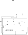
Fig. 1 is a diagram illustrating a schematic configuration of an air conditioning system according to an embodiment of the present disclosure. -
Fig. 2 is a diagram illustrating a functional configuration of a refrigerant detection device and an air conditioning system according to the first embodiment of the present disclosure. -
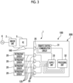
Fig. 3 is a diagram illustrating a functional configuration of a refrigerant detection device and an air conditioning system according to a second embodiment of the present disclosure. -
Fig. 4 is a diagram illustrating a functional configuration of a refrigerant detection device and an air conditioning system according to a third embodiment of the present disclosure. -
Fig. 5 is a diagram illustrating a functional configuration of a refrigerant detection device and an air conditioning system according to a modification example of the third embodiment of the present disclosure. - Hereinafter, a refrigerant detection device and an air conditioning system according to an embodiment of the present disclosure will be described with reference to
Figs. 1 and2 . - As illustrated in
Figs. 1 and2 , theair conditioning system 1 includes anindoor unit 2, an outdoor unit (not illustrated), aremote controller 5, and arefrigerant detection device 10A. - As illustrated in
Fig. 1 , theindoor unit 2 is provided in a room R provided in various buildings or structures. - The
indoor unit 2 is disposed, for example, on the ceiling Rt of the room R. - The
indoor unit 2 may be disposed on, for example, a wall Rw of the room R. - The
indoor unit 2 and the outdoor unit are connected to each other via a refrigerant circuit (not illustrated). - A refrigerant circulates through a refrigerant circuit between the
indoor unit 2 and the outdoor unit. - In the present embodiment, for example, a flammable gas is used as the refrigerant.
- The flammable gas as the refrigerant is, for example, a Freon gas such as difluoromethane.
- In the present embodiment, the specific gravity of the flammable gas is higher than that of the air, and the flammable gas sinks downward in the room R.
- As illustrated in
Fig. 2 , theindoor unit 2 is operated by an alternating-current power supply voltage supplied from thealternating power supply 6. - The
indoor unit 2 includes an AC-DC converter (not illustrated) that converts an alternating-current power supply voltage supplied from thealternating power supply 6 into a direct-current power supply voltage. - The
indoor unit 2 supplies the converted direct-current power supply voltage to theremote controller 5 and therefrigerant detection device 10A via a remotecontrol communication line 100 which will be described later. - The
remote controller 5 is for remotely operating theindoor unit 2. - The
remote controller 5 includes a button, a switch, or the like (not illustrated) for remotely operating theindoor unit 2. - As illustrated in
Fig. 1 , theremote controller 5 is disposed on, for example, a wall Rw of the room R. - The
remote controller 5 is disposed below theindoor unit 2. - The
remote controller 5 may have a lamp, a display screen, or the like indicating the operation state of theindoor unit 2. - The
remote controller 5 is connected to theindoor unit 2 via a remotecontrol communication line 100. - The
remote controller 5 is operated by a direct-current power supply voltage supplied via a remotecontrol communication line 100. - The
remote controller 5 remotely operates the operation of theindoor unit 2 via the remotecontrol communication line 100. - The
remote controller 5 transfers a command signal for remotely operating theindoor unit 2 in the room via the remotecontrol communication line 100. - The remote
control communication line 100 transfers a direct-current power supply voltage and a command signal in a superimposed manner. - As illustrated in
Fig. 2 , therefrigerant detection device 10A detects a leakage of the refrigerant from a refrigerant circuit (not illustrated). - The
refrigerant detection device 10A includes at least one ormore refrigerant sensors 20 and asignal processing kit 30A. - In the present embodiment, the
refrigerant detection device 10A includes a plurality ofrefrigerant sensors 20, asignal processing kit 30A, and asensor kit 40. - The
refrigerant sensor 20 detects the refrigerant. - In a case where the
refrigerant sensor 20 detects the refrigerant, therefrigerant sensor 20 outputs a refrigerant detection signal indicating that the refrigerant is detected. - In the present embodiment, the
refrigerant sensor 20 is provided in each of thesignal processing kit 30A and thesensor kit 40. - As illustrated in
Fig. 1 , therefrigerant sensor 20 is disposed on, for example, a wall Rw of the room R. - The
refrigerant sensor 20 is disposed within a predetermined range of height (for example, 30 cm) from the floor Rf of the room R. - As illustrated in
Fig. 2 , thesignal processing kit 30A is connected to the remotecontrol communication line 100. - The
signal processing kit 30A is supplied with a direct-current power supply voltage supplied from theindoor unit 2 via the remotecontrol communication line 100. - The
signal processing kit 30A includes a remotecontrol communication circuit 31, aprocessing unit 32, and asupply unit 33. - In the present embodiment, the
signal processing kit 30A further includes arefrigerant sensor 20. - The remote
control communication circuit 31 can be connected to the remotecontrol communication line 100. - The remote
control communication circuit 31 is connected to the remotecontrol communication line 100 via the input/output interface 35. - The remote
control communication circuit 31 can output a superimposed signal in which a pulse signal related to the refrigerant detection signal output in a case where the refrigerant is detected by therefrigerant sensor 20 is superimposed on the direct-current power supply voltage supplied from theindoor unit 2 to the remotecontrol communication line 100. - The remote
control communication circuit 31 superimposes a pulse signal related to the refrigerant detection signal on the direct-current power supply voltage and transfers the pulse signal to thesignal processing kit 30A via the remotecontrol communication line 100, thereby performing two-wire communication between the power supply to thesignal processing kit 30A and the refrigerant detection signal output from therefrigerant sensor 20 which will be described later. - The remote
control communication circuit 31 can perform bidirectional communication with theindoor unit 2 via the remotecontrol communication line 100. - The
supply unit 33 drives therefrigerant sensor 20 by receiving the direct-current power supply voltage from theindoor unit 2 via the remotecontrol communication line 100. - The
supply unit 33 can supply a sensor drive voltage based on the direct-current power supply voltage to the sensor kit 40 (refrigerant sensor 20). - The
supply unit 33 includes a DC-DC converter or the like (not illustrated) that reduces the direct-current power supply voltage supplied from theindoor unit 2 to a direct-current power supply voltage having a desired voltage, and supplies the direct-current power supply voltage reduced as a sensor drive voltage to thesensor kit 40. - The
processing unit 32 receives the direct-current power supply voltage supplied from theindoor unit 2 via the remotecontrol communication line 100 and the remotecontrol communication circuit 31. - The
processing unit 32 can acquire a refrigerant detection signal that is output in a case where the refrigerant is detected by therefrigerant sensor 20. - In a case where the
processing unit 32 acquires the refrigerant detection signal output from therefrigerant sensor 20, theprocessing unit 32 outputs the refrigerant detection signal or a signal indicating that the refrigerant detection signal has been acquired, as a pulse signal associated with the refrigerant detection signal. - The
processing unit 32 transfers the pulse signal output in a case where the refrigerant is detected by therefrigerant sensor 20 to theremote controller 5 and theindoor unit 2 via the remotecontrol communication circuit 31 and the remotecontrol communication line 100. - The
processing unit 32 is a processor such as CPU in terms of hardware. - In a case where the
indoor unit 2 receives the pulse signal output from theprocessing unit 32 in a case where the refrigerant is detected by therefrigerant sensor 20, that is, in a case where the leakage of the refrigerant is detected, for example, theindoor unit 2 stops the operation. - The
remote controller 5 may be configured to output information indicating that a leakage of the refrigerant has occurred to the outside by displaying text information, turning on a lamp, or the like when the pulse signal output in a case where the refrigerant is detected by therefrigerant sensor 20 is received from theprocessing unit 32. - In addition, in a case where the
processing unit 32 acquires the refrigerant detection signal output from therefrigerant sensor 20, theprocessing unit 32 may output to the outside that the refrigerant leakage has occurred by sounding of a buzzer (not illustrated) or the like. - The
sensor kit 40 is connected to thesignal processing kit 30A via a sensor signal line 110. - In the present embodiment, a plurality of (for example, three)
sensor kits 40 are disposed. - Each of the plurality of
sensor kits 40 is provided with address information, and theprocessing unit 32 of thesignal processing kit 30A can identify the plurality ofsensor kits 40. - Each of the
sensor kits 40 is connected to theconnection interface 38 of thesignal processing kit 30A via the sensor signal line 110. - The sensor signal line 110 is connected to the
connection interface 45 of thesensor kit 40. - The
sensor kit 40 is supplied with the direct-current power supply voltage supplied from theindoor unit 2 to thesignal processing kit 30A via the sensor signal line 110. - The
sensor kit 40 includes asensor processing unit 42, asupply unit 43, and therefrigerant sensor 20. - The
supply unit 43 drives therefrigerant sensor 20 by the direct-current power supply voltage received from thesupply unit 33 of thesignal processing kit 30A via the sensor signal line 110. - The
supply unit 43 can supply a sensor drive voltage based on the direct-current power supply voltage to therefrigerant sensor 20. - The
supply unit 43 supplies the direct-current power supply voltage received from thesupply unit 33 of thesignal processing kit 30A via the sensor signal line 110 to therefrigerant sensor 20 of thesensor kit 40 as a sensor drive voltage. - The
sensor processing unit 42 receives a direct-current power supply voltage supplied from thesupply unit 33 of thesignal processing kit 30A via the sensor signal line 110. - The
sensor processing unit 42 can acquire a refrigerant detection signal that is output in a case where the refrigerant is detected by therefrigerant sensor 20 of thesensor kit 40. - In a case where the
sensor processing unit 42 acquires the refrigerant detection signal output from therefrigerant sensor 20, thesensor processing unit 42 outputs the refrigerant detection signal or a signal indicating that the refrigerant detection signal has been acquired, as a pulse signal associated with the refrigerant detection signal. - The
sensor processing unit 42 transmits a pulse signal output in a case where the refrigerant is detected by therefrigerant sensor 20 to theprocessing unit 32 of thesignal processing kit 30A via the sensor signal line 110. - The
processing unit 32 transfers the pulse signal transmitted via the sensor signal line 110 to theindoor unit 2. - In the
refrigerant detection device 10A, thesignal processing kit 30A receives the direct-current power supply voltage supplied from theindoor unit 2 via the remotecontrol communication line 100 and the remotecontrol communication circuit 31. The remotecontrol communication circuit 31 outputs a superimposed signal in which a pulse signal related to the refrigerant detection signal is superimposed on the direct-current power supply voltage. Thesupply unit 33 supplies a sensor drive voltage based on the direct-current power supply voltage received via the remotecontrol communication circuit 31 to therefrigerant sensor 20. Accordingly, it is not necessary to separately provide a configuration for supplying power to therefrigerant sensor 20. When therefrigerant sensor 20 detects the refrigerant, therefrigerant sensor 20 outputs a refrigerant detection signal. When theprocessing unit 32 acquires the refrigerant detection signal detected by therefrigerant sensor 20, theprocessing unit 32 outputs the pulse signal related to the refrigerant detection signal to theindoor unit 2 via the remotecontrol communication line 100. In this manner, in a case where the leakage of the refrigerant is detected by therefrigerant sensor 20, a measure such as stopping theindoor unit 2 can be taken. - According to the above-described configuration, the power supply to the
refrigerant sensor 20 and the transmission of the pulse signal related to the refrigerant detection signal in therefrigerant sensor 20 are performed through the remotecontrol communication line 100. Therefore, it is not necessary to newly provide a new signal line in order to supply power to therefrigerant sensor 20 and to transmit the pulse signal related to the refrigerant detection signal in therefrigerant sensor 20. In addition, since the remotecontrol communication circuit 31 is capable of bidirectional communication with theindoor unit 2 via the remotecontrol communication line 100, in a case where a pulse signal related to the refrigerant detection signal is transmitted from the remotecontrol communication circuit 31 to theindoor unit 2, theindoor unit 2 responds to the remotecontrol communication circuit 31 as to whether or not the pulse signal is correctly received on theindoor unit 2. Therefore, even in a case where the remotecontrol communication line 100 is long and noise is likely to be superimposed on the pulse signal, in a case where the noise is superimposed on the pulse signal and the pulse signal is not correctly received on theindoor unit 2 side, the pulse signal with the superimposed noise can be discarded. As a result, it is possible to suppress the influence of noise. - In addition, the
signal processing kit 30A further includes arefrigerant sensor 20 that can detect the refrigerant. - Accordingly, the refrigerant can be detected by the
refrigerant sensor 20 included in thesignal processing kit 30A. - In addition, the
signal processing kit 30A further includes asensor kit 40 that is connected to thesignal processing kit 30A via the sensor signal line 110 and includes therefrigerant sensor 20. - Accordingly, the
sensor kit 40 including therefrigerant sensor 20 can be provided at a position different from thesignal processing kit 30A. In this case, thesignal processing kit 30A and thesensor kit 40 are connected to each other via the sensor signal line 110. The power supply to therefrigerant sensor 20 and the transmission of the refrigerant detection signal of therefrigerant sensor 20 can be performed between thesignal processing kit 30A and therefrigerant sensor 20 of thesensor kit 40 via the sensor signal line 110. - As described above, the
sensor kit 40 is connected to thesignal processing kit 30A which is connected to theindoor unit 2 via the remotecontrol communication line 100. For this reason, thesensor kit 40 is not directly connected to theindoor unit 2. Therefore, it is not necessary to assign an address for control to therefrigerant sensor 20 of thesensor kit 40. Accordingly, thesensor kit 40 can be disposed by using the remotecontrol communication line 100 without increasing the number of addresses, and the degree of design freedom of the entirerefrigerant detection device 10A can be increased. - In addition, the
sensor kit 40 further includes asensor processing unit 42. - The
sensor processing unit 42 outputs the refrigerant detection signal detected by therefrigerant sensor 20 to thesignal processing kit 30A. Therefore, on thesignal processing kit 30A side, even in a case where a plurality of thesensor kits 40 are disposed, it is possible to easily determine whichrefrigerant sensor 20 has detected the refrigerant. - In addition, the
signal processing kit 30A is connected to theremote controller 5 via the remotecontrol communication line 100. - As described above, the
signal processing kit 30A is connected to theremote controller 5 via the remotecontrol communication line 100. In this manner, the length of the remotecontrol communication line 100 connecting theremote controller 5 and thesignal processing kit 30A disposed at a lower position than theindoor unit 2 can be reduced compared to a case where theindoor unit 2 and thesignal processing kit 30A often disposed at a high position such as the ceiling Rt are directly connected to each other via the remotecontrol communication line 100. - In addition, by including the plurality of
refrigerant sensors 20, therefrigerant detection device 10A which can detect the refrigerant at the plurality of places in the room R can be configured. - Next, a second embodiment will be described with reference to
Fig. 3 . In the second embodiment, the same components as those in the first embodiment will be denoted by the same reference numerals, and detailed description thereof will be omitted. - The
signal processing kit 30B of the first embodiment includes therefrigerant sensor 20 and thesensor kit 40. On the other hand, in the second embodiment, thesensor kit 40 is not provided, and therefrigerant sensor 20 is disposed outside thesignal processing kit 30B. - As illustrated in
Fig. 3 , therefrigerant detection device 10B of theair conditioning system 1 in the present embodiment includes one or morerefrigerant sensors 20 and asignal processing kit 30B. - In the present embodiment, the
refrigerant detection device 10B includes a plurality ofrefrigerant sensors 20 and asignal processing kit 30B. - As illustrated in
Fig. 3 , thesignal processing kit 30B is connected to the remotecontrol communication line 100. - The
signal processing kit 30B is supplied with a direct-current power supply voltage supplied from theindoor unit 2 via the remotecontrol communication line 100. - The
signal processing kit 30B includes a remotecontrol communication circuit 31, aprocessing unit 32, and asupply unit 33. - The
refrigerant sensor 20 is disposed outside thesignal processing kit 30B. - The
refrigerant sensor 20 is connected to theconnection interface 38 of thesignal processing kit 30B via thesignal line 120. - In a case where the
refrigerant sensor 20 detects the refrigerant, therefrigerant sensor 20 outputs a refrigerant detection signal indicating that the refrigerant is detected. - The
processing unit 32 can acquire a refrigerant detection signal that is output in a case where the refrigerant is detected by therefrigerant sensor 20 disposed outside thesignal processing kit 30B. - In a case where the
processing unit 32 acquires the refrigerant detection signal output from therefrigerant sensor 20, theprocessing unit 32 outputs the refrigerant detection signal or a signal indicating that the refrigerant detection signal has been acquired, as a pulse signal associated with the refrigerant detection signal. - The
processing unit 32 transfers the pulse signal output in a case where the refrigerant is detected by therefrigerant sensor 20 to theremote controller 5 and theindoor unit 2 via the remotecontrol communication circuit 31 and the remotecontrol communication line 100. - Also in the
refrigerant detection device 10B, the remotecontrol communication circuit 31 can perform the bidirectional communication with theindoor unit 2 via the remotecontrol communication line 100. Therefore, in a case where noise is superimposed on the pulse signal and the pulse signal is not correctly received on theindoor unit 2 side, the pulse signal with the superimposed noise can be discarded. As a result, it is possible to suppress the influence of noise. - Next, a third embodiment will be described with reference to
Fig. 4 . In the third embodiment, the same components as those in the first embodiment and the second embodiment are denoted by the same reference numerals, and a detailed description thereof will be omitted. - In the third embodiment, the plurality of
signal processing kits 30C are provided, which is different from the first and second embodiments. - As illustrated in
Fig. 4 , therefrigerant detection device 10C of theair conditioning system 1 in the present embodiment includes one or morerefrigerant sensors 20 and asignal processing kit 30C. - In the present embodiment, the
refrigerant detection device 10C includes a plurality ofrefrigerant sensors 20 and asignal processing kit 30C. - As illustrated in
Fig. 4 , the plurality ofsignal processing kits 30C are respectively connected to the remotecontrol communication line 100. - The plurality of
signal processing kits 30C are connected in parallel to theremote controller 5 by the remotecontrol communication line 100. - A direct-current power supply voltage supplied from the
indoor unit 2 is supplied to each of thesignal processing kits 30C via the remotecontrol communication line 100. - Each of the
signal processing kits 30C includes a remotecontrol communication circuit 31, aprocessing unit 32, and asupply unit 33. - The
refrigerant sensor 20 is disposed outside each of thesignal processing kits 30C. - The
refrigerant sensor 20 is connected to theconnection interface 38 of eachsignal processing kit 30C via thesignal line 120. - The
processing unit 32 can acquire a refrigerant detection signal that is output in a case where the refrigerant is detected by therefrigerant sensor 20 disposed outside thesignal processing kit 30C. - In a case where the
processing unit 32 acquires the refrigerant detection signal output from therefrigerant sensor 20, theprocessing unit 32 outputs the refrigerant detection signal or a signal indicating that the refrigerant detection signal has been acquired, as a pulse signal associated with the refrigerant detection signal. - The
processing unit 32 transfers the pulse signal output in a case where the refrigerant is detected by therefrigerant sensor 20 to theremote controller 5 and theindoor unit 2 via the remotecontrol communication circuit 31 and the remotecontrol communication line 100. - Also in the
refrigerant detection device 10C, the remotecontrol communication circuit 31 can perform the bidirectional communication with theindoor unit 2 via the remotecontrol communication line 100. Therefore, in a case where noise is superimposed on the pulse signal and the pulse signal is not correctly received on theindoor unit 2 side, the pulse signal with the superimposed noise can be discarded. As a result, it is possible to suppress the influence of noise. - In the
refrigerant detection device 10C, a plurality of thesignal processing kits 30C are connected to the remotecontrol communication line 100. - Accordingly, the plurality of
signal processing kits 30C can be disposed via the remotecontrol communication line 100 with theindoor unit 2 as a starting point. - As illustrated in
Fig. 5 , thesignal processing kit 30C of therefrigerant detection device 10C illustrated in the third embodiment may further include atemperature sensor 50 capable of detecting the temperature of a space air-conditioned by theindoor unit 2. - In the
refrigerant detection device 10C, thetemperature sensor 50 that detects the temperature of the space air-conditioned by theindoor unit 2 is provided. In this manner, the temperature change of the space caused by the leakage of the refrigerant can be detected with a higher sensitivity. - In addition, the
temperature sensor 50 is provided in thesignal processing kit 30C disposed at a position lower than theindoor unit 2. In this manner, the temperature in the vicinity of a person in the indoor space can be more accurately detected. - Although the embodiments of the present disclosure have been described above, the embodiments are presented as examples and are not intended to limit the scope of the disclosure. The embodiments can be implemented in various other embodiments, and various omissions, replacements, and changes can be made without departing from the spirit of the disclosure. These embodiments and modifications thereof are included in the claims and the equivalents thereof as well as in the scope of the disclosure and the spirit thereof.
- For example, in the above embodiment, the
remote controller 5 is disposed between thesignal processing kits 30A to 30C and theindoor unit 2. However, the present disclosure is not limited to such a configuration. Thesignal processing kits 30A to 30C may be directly connected to the remotecontrol communication line 100 without theremote controller 5. - The
refrigerant detection devices air conditioning system 1 described in each embodiment are understood as follows, for example. -
- (1) The
refrigerant detection devices signal processing kits control communication line 100 to which the direct-current power supply voltage is supplied from theindoor unit 2, thesignal processing kits control communication circuit 31 that is connectable to the remotecontrol communication line 100, thesupply unit 33 that is capable of supplying the sensor drive voltage based on the direct-current power supply voltage to therefrigerant sensor 20, and theprocessing unit 32 that is capable of acquiring the refrigerant detection signal detected by therefrigerant sensor 20, and the remotecontrol communication circuit 31 is capable of outputting the superimposed signal in which the pulse signal related to the refrigerant detection signal is superimposed on the direct-current power supply voltage, and performing bidirectional communication with theindoor unit 2 via the remotecontrol communication line 100. - In the
refrigerant detection devices signal processing kits indoor unit 2 via the remotecontrol communication line 100 and the remotecontrol communication circuit 31. The remotecontrol communication circuit 31 outputs a superimposed signal in which a pulse signal related to the refrigerant detection signal is superimposed on the direct-current power supply voltage. Thesupply unit 33 supplies a sensor drive voltage based on the direct-current power supply voltage received via the remotecontrol communication circuit 31 to therefrigerant sensor 20. Accordingly, it is not necessary to separately provide a configuration for supplying power to therefrigerant sensor 20. When therefrigerant sensor 20 detects the refrigerant, therefrigerant sensor 20 outputs a refrigerant detection signal. When theprocessing unit 32 acquires the refrigerant detection signal detected by therefrigerant sensor 20, theprocessing unit 32 outputs the pulse signal related to the refrigerant detection signal to theindoor unit 2 via the remotecontrol communication line 100. In this way, the pulse signal related to the refrigerant detection signal is transmitted via the remotecontrol communication line 100. Therefore, it is not necessary to newly provide a signal line for transmitting the pulse signal. In addition, since the remotecontrol communication circuit 31 is capable of bidirectional communication with theindoor unit 2 via the remotecontrol communication line 100, for example, in a case where a pulse signal related to a refrigerant detection signal is transmitted from the remotecontrol communication circuit 31 to theindoor unit 2, theindoor unit 2 can respond to the remotecontrol communication circuit 31 as to whether or not the pulse signal is correctly received in theindoor unit 2 or the like. Therefore, even in a case where the remotecontrol communication line 100 is long and noise is likely to be superimposed on the pulse signal, in a case where the noise is superimposed on the pulse signal and the pulse signal is not correctly received on theindoor unit 2 side, the pulse signal with the superimposed noise can be discarded. As a result, it is possible to suppress the influence of noise. - (2) The
refrigerant detection device 10A according to a second aspect is therefrigerant detection device 10A according to (1), in which thesignal processing kit 30A further includes therefrigerant sensor 20 capable of detecting the refrigerant. - Accordingly, the refrigerant can be detected by the
refrigerant sensor 20 included in thesignal processing kit 30A. - (3) The
refrigerant detection device 10A according to a third aspect is therefrigerant detection device 10A according to (1) or (2), further including thesensor kit 40 that is connected to thesignal processing kit 30A via the sensor signal line 110 and includes therefrigerant sensor 20 capable of detecting the refrigerant. - In this manner, in a case where the
sensor kit 40 including therefrigerant sensor 20 is provided at a position different from thesignal processing kit 30A, thesignal processing kit 30A and thesensor kit 40 are connected to each other via the sensor signal line 110. The power supply to therefrigerant sensor 20 and the transmission of the refrigerant detection signal of therefrigerant sensor 20 can be performed between thesignal processing kit 30A and therefrigerant sensor 20 of thesensor kit 40 via the sensor signal line 110. - As described above, the
sensor kit 40 is connected to thesignal processing kit 30A which is connected to theindoor unit 2 via the remotecontrol communication line 100. For this reason, thesensor kit 40 is not directly connected to theindoor unit 2. Therefore, it is not necessary to assign an address for control to therefrigerant sensor 20 of thesensor kit 40. Accordingly, thesensor kit 40 can be disposed by using the remotecontrol communication line 100 without increasing the number of addresses, and the degree of design freedom of the entirerefrigerant detection device 10A can be increased. - (4) The
refrigerant detection device 10A according to a fourth aspect is therefrigerant detection device 10A according to (3), in which thesensor kit 40 further includes thesensor processing unit 42 that is capable of acquiring the refrigerant detection signal detected by therefrigerant sensor 20 and outputting the refrigerant detection signal to thesignal processing kit 30A. - In this manner, the
sensor processing unit 42 outputs the refrigerant detection signal detected by therefrigerant sensor 20 to thesignal processing kit 30A. Therefore, on thesignal processing kit 30A side, even in a case where a plurality of thesensor kits 40 are disposed, it is possible to easily determine whichrefrigerant sensor 20 has detected the refrigerant. - (5) The
refrigerant detection device 10C according to a fifth aspect is therefrigerant detection device 10C according to any one of (1) to (4), in which a plurality of thesignal processing kits 30C are connected to the remotecontrol communication line 100. - Accordingly, the plurality of
signal processing kits 30C are connected to the remotecontrol communication line 100, so that the plurality ofsignal processing kits 30C can be disposed via the remotecontrol communication line 100 with theindoor unit 2 as a starting point. - (6) The
refrigerant detection devices refrigerant detection devices remote controller 5 that is connected to the remotecontrol communication line 100 and that is capable of performing remote operation of theindoor unit 2, in which thesignal processing kits remote controller 5 via the remotecontrol communication line 100. - Accordingly, the
signal processing kits remote controller 5 via the remotecontrol communication line 100, so that the length of the remotecontrol communication line 100 connecting theremote controller 5 and thesignal processing kits indoor unit 2 can be reduced, compared to a case where theindoor unit 2 and thesignal processing kits control communication line 100. - (7) The
refrigerant detection devices refrigerant detection devices refrigerant sensors 20. - Accordingly, by including the plurality of
refrigerant sensors 20, therefrigerant detection devices - (8) The
refrigerant detection devices refrigerant detection devices signal processing kits temperature sensor 50 capable of detecting the temperature of the space air-conditioned by theindoor unit 2. - Accordingly, the
signal processing kits temperature sensor 50 that detects the temperature of the space air-conditioned by theindoor unit 2 with thetemperature sensor 50. In this manner, thesignal processing kits - (9) The
air conditioning system 1 according to a ninth aspect includes therefrigerant detection devices - Accordingly, the
air conditioning system 1 including therefrigerant detection devices - According to the refrigerant detection device and the air conditioning system of the present disclosure, the influence of noise can be suppressed.
-
- 1: Air conditioning system
- 2: Indoor unit
- 5: Remote controller
- 6: Alternating power supply
- 10A to 10C: Refrigerant detection device
- 20: Refrigerant sensor
- 30A to 30C: Signal processing kit
- 31: Remote control communication circuit
- 32: Processing unit
- 33: Supply unit
- 35: Input/output interface
- 38: Connection interface
- 40: Sensor kit
- 42: Sensor processing unit
- 43: Supply unit
- 45: Connection interface
- 50: Temperature sensor
- 100: Remote control communication line
- 110: Sensor signal line
- 120: Signal line
- R: Room
- Rf: Floor
- Rt: Ceiling
- Rw: Wall
Claims (9)
- A refrigerant detection device comprising:a signal processing kit that is connected to a remote control communication line to which a direct-current power supply voltage is supplied from an indoor unit,wherein the signal processing kit includesa remote control communication circuit that is connectable to the remote control communication line,a supply unit that is capable of supplying a sensor drive voltage based on the direct-current power supply voltage to a refrigerant sensor, anda processing unit that is capable of acquiring a refrigerant detection signal detected by the refrigerant sensor, andthe remote control communication circuit is capable ofoutputting a superimposed signal in which a pulse signal related to the refrigerant detection signal is superimposed on the direct-current power supply voltage, andperforming bidirectional communication with the indoor unit via the remote control communication line.
- The refrigerant detection device according to claim 1,
wherein the signal processing kit further includes the refrigerant sensor that is capable of detecting a refrigerant. - The refrigerant detection device according to claim 1 or 2, further comprising:
a sensor kit that is connected to the signal processing kit via a sensor signal line and includes the refrigerant sensor capable of detecting a refrigerant. - The refrigerant detection device according to claim 3,
wherein the sensor kit further includes a sensor processing unit that is capable of acquiring the refrigerant detection signal detected by the refrigerant sensor and outputting the refrigerant detection signal to the signal processing kit. - The refrigerant detection device according to claim 1 or 2,
wherein a plurality of the signal processing kits are connected to the remote control communication line. - The refrigerant detection device according to claim 1 or 2, further comprising:a remote controller connected to the remote control communication line and capable of performing remote operation of the indoor unit,wherein the signal processing kit is connected to the remote controller via the remote control communication line.
- The refrigerant detection device according to claim 1 or 2, comprising:
a plurality of the refrigerant sensors. - The refrigerant detection device according to claim 1 or 2,
wherein the signal processing kit further includes a temperature sensor that is capable of detecting a temperature of a space which is air-conditioned by the indoor unit. - An air conditioning system comprising:
the refrigerant detection device according to claim 1 or 2.
Applications Claiming Priority (2)
| Application Number | Priority Date | Filing Date | Title |
|---|---|---|---|
| JP2022077549A JP2023166774A (en) | 2022-05-10 | 2022-05-10 | Refrigerant detector and air conditioning system |
| PCT/JP2023/017299 WO2023219062A1 (en) | 2022-05-10 | 2023-05-08 | Refrigerant detection device and air conditioning system |
Publications (2)
| Publication Number | Publication Date |
|---|---|
| EP4498010A1 true EP4498010A1 (en) | 2025-01-29 |
| EP4498010A4 EP4498010A4 (en) | 2025-06-25 |
Family
ID=88730536
Family Applications (1)
| Application Number | Title | Priority Date | Filing Date |
|---|---|---|---|
| EP23803539.8A Pending EP4498010A4 (en) | 2022-05-10 | 2023-05-08 | REFRIGERANT DETECTION DEVICE AND AIR CONDITIONING SYSTEM |
Country Status (3)
| Country | Link |
|---|---|
| EP (1) | EP4498010A4 (en) |
| JP (1) | JP2023166774A (en) |
| WO (1) | WO2023219062A1 (en) |
Families Citing this family (1)
| Publication number | Priority date | Publication date | Assignee | Title |
|---|---|---|---|---|
| JP7809254B1 (en) * | 2024-12-19 | 2026-01-30 | ボッシュホームコンフォートジャパン株式会社 | air conditioning equipment |
Family Cites Families (9)
| Publication number | Priority date | Publication date | Assignee | Title |
|---|---|---|---|---|
| JP2013181700A (en) * | 2012-03-01 | 2013-09-12 | Panasonic Corp | System for controlling air-conditioned environment |
| JP2017053571A (en) * | 2015-09-10 | 2017-03-16 | ジョンソンコントロールズ ヒタチ エア コンディショニング テクノロジー(ホンコン)リミテッド | Refrigerant leak detector inspection system and air conditioning system |
| CN109073263A (en) * | 2016-05-13 | 2018-12-21 | 三菱电机株式会社 | Air conditioner |
| JP6911441B2 (en) | 2017-03-24 | 2021-07-28 | 三菱電機株式会社 | Environmental monitoring device |
| GB2575606C (en) * | 2017-05-31 | 2021-04-21 | Mitsubishi Electric Corp | Air-conditioning apparatus |
| JP6890188B2 (en) * | 2017-11-15 | 2021-06-18 | 日立ジョンソンコントロールズ空調株式会社 | Air conditioner |
| JP6746253B1 (en) * | 2019-06-04 | 2020-08-26 | 日立ジョンソンコントロールズ空調株式会社 | Air conditioner |
| CN213426160U (en) * | 2020-09-11 | 2021-06-11 | 深圳和而泰智能控制股份有限公司 | Single-wire communication conversion circuit, single-wire communication device and equipment |
| JP7252473B2 (en) | 2020-11-12 | 2023-04-05 | サミー株式会社 | pachinko machine |
-
2022
- 2022-05-10 JP JP2022077549A patent/JP2023166774A/en active Pending
-
2023
- 2023-05-08 EP EP23803539.8A patent/EP4498010A4/en active Pending
- 2023-05-08 WO PCT/JP2023/017299 patent/WO2023219062A1/en not_active Ceased
Also Published As
| Publication number | Publication date |
|---|---|
| EP4498010A4 (en) | 2025-06-25 |
| JP2023166774A (en) | 2023-11-22 |
| WO2023219062A1 (en) | 2023-11-16 |
Similar Documents
| Publication | Publication Date | Title |
|---|---|---|
| JP6584262B2 (en) | Support system | |
| EP1666805A1 (en) | Apparatus for testing an air conditioner | |
| US8164466B2 (en) | Apparatus and method for detecting a communication abnormality in a multi-type air conditioner | |
| EP3567837B1 (en) | Radio communication system | |
| JP2019018987A (en) | Elevator report control system and elevator report control method | |
| WO2023219062A1 (en) | Refrigerant detection device and air conditioning system | |
| CN112740717B (en) | Air Conditioning System | |
| EP3859221B1 (en) | Air conditioning system and application program | |
| JP2016194840A (en) | Test system | |
| JP2002279547A (en) | Disaster prevention monitoring equipment and compound alarm | |
| US12627524B2 (en) | Air treatment apparatus | |
| JP6718550B2 (en) | Support system | |
| EP2785148A2 (en) | Electrical apparatus control system | |
| KR200436731Y1 (en) | Fire Extinguisher Inspection System using Zigbee | |
| US12590724B2 (en) | Air-conditioning system and control device | |
| KR102107651B1 (en) | A system for management of an air-conditioning unit | |
| JP2009259657A (en) | Illumination control system | |
| JP4161180B2 (en) | Doorphone remote testing device | |
| JP7843865B2 (en) | Air conditioning system and control method for the air conditioning system | |
| JP7144486B2 (en) | Management equipment and communication system | |
| JP2008121911A (en) | Free-access underfloor air-conditioning state measuring device | |
| JPH10115449A (en) | Air conditioner wired remote control | |
| KR20090052748A (en) | Automatic Supervision Method and System of Multi-Air Conditioner | |
| JPH11201536A (en) | Remote control and receiver | |
| JP2021072228A (en) | Communication failure estimation system for lighting |
Legal Events
| Date | Code | Title | Description |
|---|---|---|---|
| STAA | Information on the status of an ep patent application or granted ep patent |
Free format text: STATUS: THE INTERNATIONAL PUBLICATION HAS BEEN MADE |
|
| PUAI | Public reference made under article 153(3) epc to a published international application that has entered the european phase |
Free format text: ORIGINAL CODE: 0009012 |
|
| STAA | Information on the status of an ep patent application or granted ep patent |
Free format text: STATUS: REQUEST FOR EXAMINATION WAS MADE |
|
| 17P | Request for examination filed |
Effective date: 20241023 |
|
| AK | Designated contracting states |
Kind code of ref document: A1 Designated state(s): AL AT BE BG CH CY CZ DE DK EE ES FI FR GB GR HR HU IE IS IT LI LT LU LV MC ME MK MT NL NO PL PT RO RS SE SI SK SM TR |
|
| A4 | Supplementary search report drawn up and despatched |
Effective date: 20250526 |
|
| RIC1 | Information provided on ipc code assigned before grant |
Ipc: F25B 49/02 20060101ALI20250520BHEP Ipc: F24F 11/89 20180101ALI20250520BHEP Ipc: F24F 11/56 20180101ALI20250520BHEP Ipc: F24F 11/36 20180101ALI20250520BHEP Ipc: F24F 11/50 20180101AFI20250520BHEP |
|
| DAV | Request for validation of the european patent (deleted) | ||
| DAX | Request for extension of the european patent (deleted) |