EP4498000A1 - Flat spray fuel injectors - Google Patents
Flat spray fuel injectors Download PDFInfo
- Publication number
- EP4498000A1 EP4498000A1 EP24190964.7A EP24190964A EP4498000A1 EP 4498000 A1 EP4498000 A1 EP 4498000A1 EP 24190964 A EP24190964 A EP 24190964A EP 4498000 A1 EP4498000 A1 EP 4498000A1
- Authority
- EP
- European Patent Office
- Prior art keywords
- fuel
- slots
- flat spray
- spaced apart
- spray
- Prior art date
- Legal status (The legal status is an assumption and is not a legal conclusion. Google has not performed a legal analysis and makes no representation as to the accuracy of the status listed.)
- Granted
Links
Images


Classifications
-
- F—MECHANICAL ENGINEERING; LIGHTING; HEATING; WEAPONS; BLASTING
- F23—COMBUSTION APPARATUS; COMBUSTION PROCESSES
- F23R—GENERATING COMBUSTION PRODUCTS OF HIGH PRESSURE OR HIGH VELOCITY, e.g. GAS-TURBINE COMBUSTION CHAMBERS
- F23R3/00—Continuous combustion chambers using liquid or gaseous fuel
- F23R3/28—Continuous combustion chambers using liquid or gaseous fuel characterised by the fuel supply
- F23R3/283—Attaching or cooling of fuel injecting means including supports for fuel injectors, stems, or lances
-
- F—MECHANICAL ENGINEERING; LIGHTING; HEATING; WEAPONS; BLASTING
- F23—COMBUSTION APPARATUS; COMBUSTION PROCESSES
- F23D—BURNERS
- F23D11/00—Burners using a direct spraying action of liquid droplets or vaporised liquid into the combustion space
- F23D11/10—Burners using a direct spraying action of liquid droplets or vaporised liquid into the combustion space the spraying being induced by a gaseous medium, e.g. water vapour
- F23D11/106—Burners using a direct spraying action of liquid droplets or vaporised liquid into the combustion space the spraying being induced by a gaseous medium, e.g. water vapour medium and fuel meeting at the burner outlet
- F23D11/107—Burners using a direct spraying action of liquid droplets or vaporised liquid into the combustion space the spraying being induced by a gaseous medium, e.g. water vapour medium and fuel meeting at the burner outlet at least one of both being subjected to a swirling motion
-
- F—MECHANICAL ENGINEERING; LIGHTING; HEATING; WEAPONS; BLASTING
- F23—COMBUSTION APPARATUS; COMBUSTION PROCESSES
- F23R—GENERATING COMBUSTION PRODUCTS OF HIGH PRESSURE OR HIGH VELOCITY, e.g. GAS-TURBINE COMBUSTION CHAMBERS
- F23R3/00—Continuous combustion chambers using liquid or gaseous fuel
- F23R3/02—Continuous combustion chambers using liquid or gaseous fuel characterised by the air-flow or gas-flow configuration
- F23R3/04—Air inlet arrangements
- F23R3/10—Air inlet arrangements for primary air
- F23R3/12—Air inlet arrangements for primary air inducing a vortex
- F23R3/14—Air inlet arrangements for primary air inducing a vortex by using swirl vanes
-
- F—MECHANICAL ENGINEERING; LIGHTING; HEATING; WEAPONS; BLASTING
- F23—COMBUSTION APPARATUS; COMBUSTION PROCESSES
- F23D—BURNERS
- F23D2900/00—Special features of, or arrangements for burners using fluid fuels or solid fuels suspended in a carrier gas
- F23D2900/11101—Pulverising gas flow impinging on fuel from pre-filming surface, e.g. lip atomizers
Definitions
- This disclosure relates to fuel injectors, and more particularly, to flat spray fuel injectors for gas turbine engines.
- Atomized flat spray fuel injectors for use within a dome air swirler or swirl cups provide a simpler design than an array of multiple pressure atomizers which have traditionally been used. Atomized flat spray fuel injectors are more compact than prefilmer style injectors and require less air velocity to atomize. Additionally, the flat spray may be staged among alternate circuits for efficiency purpose, for example, droplet placement into the air stream. Atomized flat spray injectors provide for a variety of spray capabilities that are able to cover different combustor geometries. For example, spray capabilities include both axial angle coverage (e.g., pie shape) and conical angle coverage, which is an issue with traditional prefilmer style injectors.
- axial angle coverage e.g., pie shape
- conical angle coverage which is an issue with traditional prefilmer style injectors.
- Purposeful bias in fuel placement is created to account for a variety of combustor geometries.
- targeted, atomized spray can be directed to an ignitor, such as a pilot.
- atomized flat spray fuel injectors allow for individual metering of fuel prior to filming, resulting in multiple fuel patterns and minimal uniformity of fuel patterns.
- the non-uniform spray accounts for combustor geometries (e.g., bias in compressor diffuser discharge air profile resulting in non-uniform spray) and is particularly advantageous for large fuel injectors, such as ones used in lean combustion.
- the subject disclosure is directed to a new and useful fuel injector assembly for a gas turbine engine.
- the fuel injector assembly has a fuel nozzle including a radial feed arm with an elongated axially extending nozzle portion having a central axis extending therethrough.
- the elongated nozzle portion has a distal spray tip with a frusto-conical outer surface and a planar front surface.
- a primary pressure atomizer port is centrally provided in the planar front surface of the distal spray tip and a set of circumferentially spaced apart secondary flat spray slots are provided in the frusto-conical outer surface of the distal spray tip.
- the secondary flat spray slots have non-uniform flow rates.
- the primary pressure atomizer port is operatively associated with a primary pressure atomizer within the distal spray tip of the nozzle portion of the fuel nozzle.
- the primary pressure atomizer includes an atomizing tip portion which the primary pressure atomizer port extends through.
- the primary pressure atomizer further includes a fuel swirler surrounded by the atomizing tip portion.
- the fuel swirler has a front surface which abuts an inner wall of the atomizing tip portion.
- the fuel swirler has a plurality of offset slots and a main swirler. The fuel exits the plurality of offset slots and is directed into the main swirler by the inner wall of the primary pressure atomizer and through the primary pressure atomizer port.
- a set of circumferentially spaced apart tertiary flat spray slots are provided in the frusto-conical outer surface rearward of the set of circumferentially spaced apart secondary flat spray slots.
- a primary fuel supply circuit extends through the fuel nozzle for supplying fuel to the primary pressure atomizer port.
- a secondary fuel supply circuit extends through the fuel nozzle for supplying fuel to the set of circumferentially spaced apart secondary flat spray slots.
- a tertiary fuel supply circuit extends through the fuel nozzle for supplying fuel to the set of circumferentially spaced apart tertiary flat spray slots.
- each flat spray slot in the set of circumferentially spaced apart secondary flat spray slots is a splash plate style spray slot.
- each flat spray slot in the set of circumferentially spaced apart secondary flat spray slots is a pressure washer style spray slot.
- each flat spray slot in the set of circumferentially spaced apart tertiary flat spray slots is a splash plate style spray slot.
- each flat spray slot in the set of circumferentially spaced apart tertiary flat spray slots is a pressure washer style spray slot.
- the set of circumferentially spaced apart secondary flat spray slots includes at least three circumferentially spaced apart secondary flat spray slots. In certain embodiments, the set of circumferentially spaced apart tertiary flat spray slots includes at least three circumferentially spaced apart tertiary flat spray slots. In one embodiment, the set of circumferentially spaced apart secondary flat spray slots and the set of circumferentially spaced apart tertiary flat spray slots can be axially aligned with one another relative to the central axis of the elongated nozzle portion. In another embodiment, the set of circumferentially spaced apart secondary flat spray slots and the set of circumferentially spaced apart tertiary flat spray slots can be axially offset from one another relative to the central axis of the elongated nozzle portion.
- the fuel injector assembly further includes an air swirler operatively associated with the distal spray tip.
- the air swirler is a dome air swirler.
- the air swirler is an air swirler cup.
- the primary pressure atomizer port is adapted and configured to issue a conic fuel spray.
- FIG. 1 an engine casing designated generally by reference numeral 50, which includes a fuel injector assembly 100 constructed in accordance with an embodiment of the subject disclosure that is designed to cover various combustor geometries and provide targeted flat spray.
- the fuel injector assembly 100 includes a fuel nozzle 102 having a radial feed arm 104 with an elongated axially extending nozzle portion 106, which has a central axis "X" extending therethrough.
- the fuel nozzle 102 is received within the engine casing 50 through an inlet hole 52 and is secured in place by an inlet fitting 54.
- the fuel nozzle 102 is supplied fuel from a fuel supply when in operation.
- fuel is sprayed out of the elongated nozzle portion 106 into an air swirler 118 and through to a combustion chamber 56.
- the elongated nozzle portion 106 has a distal spray tip 108 (e.g., as shown in Fig. 1 ) with a frusto-conical outer surface 110 and a planar front surface 112.
- a primary pressure atomizer port 114 is centrally provided in the planar front surface 112 of the distal spray tip 108 and a set of circumferentially spaced apart secondary flat spray slots 116 (e.g., secondary flat spray slots 116a-116d, as shown in Fig. 3 ) are provided in the frusto-conical outer surface 110 of the distal spray tip 108.
- the secondary flat spray slots 116 have non-uniform flow rates (e.g., injection characteristic, such as angle, can vary for improvement with uneven air flow).
- injection characteristic such as angle
- the pressure atomizing port 114 meters the flow rate of exiting fuel into a conic spray pattern 144, as shown in Fig. 4 , and the secondary flat spray slots 116a-116d create a flat spray pattern 146, as shown in Figs. 3 and 4 .
- the fuel injector assembly 100 further includes an air swirler 118 operatively associated with the distal spray tip 108.
- a diffuser 120 is separate from, but operatively associated with the fuel injector assembly 100 for guiding compressor airflow towards the air swirler.
- the diffuser 120 has a radially inner wall 120a and a radially outer wall 120b, as best shown in Fig. 2 . In operation, air flows through the diffuser 120 and surrounds the elongated nozzle portion 106 of the fuel nozzle 102 in an uneven pattern, as indicated by the directional flow arrows 148 in Fig. 1 .
- the air flow around the elongated nozzle portion 106 may have a concentrated air flow region around the center and creates dense and sparse air feed into air swirler 118.
- Fuel can be more efficiently placed into the high/low air flow regions by the independent calibration of particular injection sites (e.g., flat spray slots 116 & 136).
- the secondary flat spray slots 116a and 116c may be higher fuel flow than the secondary flat spray slots 116b and 116d.
- the air swirler 118 is an air swirler cup. In certain other embodiments, the air swirler 118 is a dome air swirler. Any other suitable type of air swirler is contemplated herein. In Figs. 1 and 2 , the air swirler 118 is shown within a combustion chamber 56 of the gas turbine engine. It is envisioned that pilot fuel flow from the fuel nozzle 102 can be targeted, for example, directed at the ignitor 58 during engine start-up (e.g., as shown in Fig. 1 ).
- втори ⁇ ество 116a-116d are shown spaced circumferentially around the central axis X.
- the four secondary flat spray slots 116a-116d can be spaced apart 90 degrees from each other (e.g., as shown in Fig. 3 ), or can include any other suitable arrangement.
- Any suitable length, arc, width, and number of secondary flat spray slots 116 is contemplated herein.
- certain secondary flat spray slots 116 may have a larger flow number and a wider angle resulting in one type of fuel flow pattern, while other secondary flat spray slots 116 may have a lower flow number and a narrower angle resulting in a different fuel flow pattern.
- the secondary flat spray slots 116a-116d are embedded or otherwise formed within the frusto-conical outer surface 110.
- the secondary flat spray slots 116a-116d are shown with fuel being sprayed therethrough, resulting in the flat spray pattern 146.
- Each secondary flat spray slot 116a-116d can be different as described above, to provide for different flow rates and flow patterns.
- the distal spray tip 108 is shown within the air swirler 118.
- the fuel injector assembly 100 is shown in operation and a fuel spray is shown coming from the pressure atomizer port 114 as well as from the secondary flat spray slots 116.
- the fuel coming from the pressure atomizer port is the conic spray pattern 144 and the fuel coming from the secondary flat spray slots 116a-116d is the flat spray pattern 146.
- the location of the secondary flat spray slots 116 around the central axis X can each have unique performance characteristics. For example, top and/or bottom location spray slots may be a lower flow number and a narrower angle and side location spray slots may be a larger flow number and wider angle.
- the primary pressure atomizer port 114 is operatively associated with a primary pressure atomizer 122 within the distal spray tip 108 of the nozzle portion 106 of the fuel nozzle 102.
- the primary pressure atomizer 122 is a common pressure atomizer used in the primary (e.g., pilot) fuel circuit 138.
- the primary pressure atomizer 122 includes an atomizing tip portion 124 which the primary pressure atomizer port 114 extends through.
- the primary pressure atomizer 122 further includes a fuel swirler 126 surrounded by the atomizing tip portion 124.
- the fuel swirler 126 has a front surface 128 which abuts an inner wall 130 of the atomizing tip portion 124.
- the fuel swirler 126 has a plurality of offset slots 132a, 132b, e.g., as best shown in Fig. 10 , and a main swirler 134.
- the plurality of offset slots 132a, 132b aid in imparting centrifugal swirling. Any number of offset slots 132 is contemplated herein.
- the fuel exits the plurality of offset slots 132a, 132b and is directed into the main swirler 134 by the inner wall 130 of the primary pressure atomizer 122 and through the primary pressure atomizer port 114.
- a primary fuel supply circuit 138 extends through the fuel nozzle 102 for supplying fuel to the primary pressure atomizer port 114.
- a secondary fuel supply circuit 140 extends through the fuel nozzle 102 for supplying fuel to the set of circumferentially spaced apart secondary flat spray slots 116.
- the primary fuel circuit 138 and secondary fuel circuit 140 are all supplied fuel independently and can each be staged on and/or off as best suits combustion performance (e.g., for power necessity, burn efficiency, emissions, etc.).
- each flat spray slot in the set of circumferentially spaced apart secondary flat spray slots 116 is a splash plate style spray slot (e.g., as shown by the secondary flat spray slots of Fig. 5 ).
- each flat spray slot in the set of circumferentially spaced apart secondary flat spray slots 116 is a pressure washer style spray slot (e.g., a pressure washer style spray slot is shown in Fig. 11 for the tertiary flat spray slots 136).
- the secondary flat spray slots 116 can be any arrangement of pressure washer and or splash plate style slots.
- the pressure washer style spray slots may be created by a keyseat, a double angle shank, or thread mill style cutting tool.
- the splash plate style spray slots may be created by a keyseat style cutting tool.
- Each of the secondary fuel circuits 140 include respective nominally central passages 143, e.g., as shown in Figs. 10, and 11 , which are operatively connected to the secondary flat spray slots 116.
- the nominally central passages 143a of the washer pressure washer style spray slots e.g., as shown in Fig 11
- the nominally central passages 143b of the splash plate style spray slots can be covered completely or partially by the opposite side of the secondary flat spray slots 116.
- the nominally central passage 143b may partially intersect the opposite side of the secondary flat spray slots 116 without impacting the spray performance.
- the fuel injector assembly further includes a set of circumferentially spaced apart tertiary flat spray slots 136 provided in the frusto-conical outer surface 110 rearward of the set of circumferentially spaced apart secondary flat spray slots 116.
- the tertiary flat spray slots 136 have non-uniform flow rates (e.g., injection characteristic, such as angle, can vary for improvement with uneven air flow)
- the fuel injector is shown in operation as described above with respect to Fig. 1 . Fuel is sprayed out of the elongated nozzle portion 106 into an air swirler 118 and into the combustion chamber 56.
- the elongated nozzle portion 106 includes the distal spray tip 108 (e.g., as shown in Fig. 6 ) with the frusto-conical outer surface 110 and the planar front surface 112.
- the primary pressure atomizer port 114 is centrally provided in the planar front surface 112 of the distal spray tip 108 and a set of circumferentially spaced apart secondary flat spray slots 116 and circumferentially spaced tertiary flat spray slots 136 (e.g., three tertiary spray slots 136a-136c as shown in Fig. 8 ) are provided in the frusto-conical outer surface 110 of the distal spray tip 108.
- the pressure atomizing port 114 meters the flow rate of exiting fuel into a conic spray pattern 144, e.g., as shown in Fig. 9 , and the secondary flat spray slots 116 and tertiary flat spray slots 136 create a flat spray pattern 146, as shown in Figs. 8 and 9 .
- three secondary flat spray slots 116a-116c are shown spaced circumferentially around the central axis X and three tertiary flat spray slots 136a-136c are shown rearward of the secondary flat spray slots 116a-116c and circumferentially spaced around the central axis X.
- the three secondary flat spray slots 116a-116c and the tertiary flat spray slots 136a-136c can be spaced apart 120 degrees from each other, e.g., as shown in Fig 8 , or they can include any other suitable arrangement.
- the set of circumferentially spaced apart secondary flat spray slots 116a-116c and the set of circumferentially spaced apart tertiary flat spray slots 136a-136c can be axially aligned with one another relative to the central axis X of the elongated nozzle portion 106.
- each of the secondary flat spray slots 116a-116c can be spaced apart 120 degrees from each other and each of the tertiary flat spray slots 136 can be reward of the secondary flat spray slots 116a-116c and can also be spaced 120 degrees apart from each other.
- the set of circumferentially spaced apart secondary flat spray slots 116a-116c and the set of circumferentially spaced apart tertiary flat spray slots 136a-136c can be axially offset from one another relative to the central axis X of the elongated nozzle portion 106.
- the secondary flat spray slots 116a-116c can be spaced apart 120 degrees from one another around the central axis and the tertiary flat spray slots 136a-136c can be reward of the secondary flat spray slots 116a-116c and spaced apart from each other 240 degrees from each other.
- the secondary flat spray slots 116a-116c and tertiary flat spray slots 136a-136c are embedded within the frusto-conical outer surface 110.
- the secondary flat spray slots 116a-116c and tertiary flat spray slots 136a-136c are shown with fuel being sprayed therethrough, resulting in the flat spray pattern 146.
- Each secondary flat spray slot 116a-116c and tertiary flat spray slot 136a-136c can be different as described above, to provide for different flow rates and flow patterns.
- the distal spray tip 108 is shown within the air swirler 118.
- the fuel injector assembly 100 is shown in operation and a fuel spray is shown coming from the pressure atomizer port 114 as well as from the secondary flat spray slots 116 and the tertiary flat spray slots 136.
- the fuel coming from the pressure atomizer port is the conic spray pattern 144 and the fuel coming from the secondary flat spray slots 116 and the tertiary flat spray slots 136 is the flat spray pattern 146.
- the location of the secondary flat spray slots 116 and the tertiary flat spray slots 136 around the central axis X can each have unique performance characteristics.
- top and/or bottom location spray slots may be a lower flow number and a narrower angle and side location spray slots may be a larger flow number and wider angle.
- a primary fuel supply circuit 138 extends through the fuel nozzle 102 for supplying fuel to the primary pressure atomizer port 114.
- a secondary fuel supply circuit 140 extends through the fuel nozzle 102 for supplying fuel to the set of circumferentially spaced apart secondary flat spray slots 116.
- a tertiary fuel supply circuit 142 extends through the fuel nozzle 102 for supplying fuel to the set of circumferentially spaced apart tertiary flat spray slots 136.
- the primary fuel circuit 138, secondary fuel circuit 140, and tertiary fuel circuit 142 are all supplied independently and can each be staged on and/or off as best suits combustion performance, e.g., for power necessity, burn efficiency, emissions, etc.).
- each flat spray slot in the set of circumferentially spaced apart secondary flat spray slots 116 is a splash plate style spray slot.
- each flat spray slot in the set of circumferentially spaced apart secondary flat spray slots 116 is a pressure washer style spray slot.
- each flat spray slot in the set of circumferentially spaced apart tertiary flat spray slots 136 is a splash plate style spray slot.
- each flat spray slot in the set of circumferentially spaced apart tertiary flat spray slots 136 is a pressure washer style spray slot. As shown in Fig. 10 , the tertiary flat spray slots 136 are of the flat spray style slot. As shown in Fig. 11 , the tertiary flat spray slots 136 are of the pressure washer style spray slot.
- the secondary flat spray slots 116 and tertiary flat spray slots 136 can be any arrangement of washer and or splash plate style slots.
- the pressure washer style spray slots may be created by a keyseat, a double angle shank, or thread mill style cutting tool.
- the splash plate style spray slots may be created by a keyseat style cutting tool.
- each of the secondary fuel circuits 140 and tertiary fuel circuits 142 include respective nominally central passages 143, e.g., as shown in Figs. 9 and 10 , which are operatively connected to the secondary flat spray slots 116 and the tertiary flat spray slots 136.
- the nominally central passages 143a of the washer pressure washer style spray slots have an eccentric open area between the nominally central passage 143a and the secondary flat spray slots 166 and/or the tertiary flat spray slots 136 to perform flow rate metering of exiting fuel and generates flat fuel spray.
- the nominally central passages 143b of the splash plate style spray slots can be covered completely or partially by the opposite side of the secondary flat spray slots 116 and/or the tertiary flat spray slots 136.
- the nominally central passage 143b may partially intersect the opposite side of the secondary flat spray slots 116 and/or the tertiary flat spray slots 136 without impacting the spray performance.
Landscapes
- Engineering & Computer Science (AREA)
- Chemical & Material Sciences (AREA)
- Combustion & Propulsion (AREA)
- Mechanical Engineering (AREA)
- General Engineering & Computer Science (AREA)
- Fuel-Injection Apparatus (AREA)
- Nozzles For Spraying Of Liquid Fuel (AREA)
Abstract
Description
- This disclosure relates to fuel injectors, and more particularly, to flat spray fuel injectors for gas turbine engines.
- There is a need for alternate injection styles for multi-circuit liquid fuel injectors for gas turbine engines. More specifically, there is a need for injecting fuel at operating conditions that may not be ideal for other traditional forms of injection, such as jet and prefilmer style injectors. Traditionally, complex fuel injector systems have been used for multi-circuit fuel injector systems. Due to the high temperatures within the environments of these systems, there is concern for the durability of such systems during long term use. For example, carbon growth on external faces or within the outlet features of such systems is an ongoing risk. Fuel passages must be thermally designed to prevent this carbon growth, or coking. Additionally, traditional systems also come with the risk of potential for streaky spray.
- Atomized flat spray fuel injectors for use within a dome air swirler or swirl cups provide a simpler design than an array of multiple pressure atomizers which have traditionally been used. Atomized flat spray fuel injectors are more compact than prefilmer style injectors and require less air velocity to atomize. Additionally, the flat spray may be staged among alternate circuits for efficiency purpose, for example, droplet placement into the air stream. Atomized flat spray injectors provide for a variety of spray capabilities that are able to cover different combustor geometries. For example, spray capabilities include both axial angle coverage (e.g., pie shape) and conical angle coverage, which is an issue with traditional prefilmer style injectors.
- Purposeful bias in fuel placement is created to account for a variety of combustor geometries. For example, targeted, atomized spray can be directed to an ignitor, such as a pilot. For example, atomized flat spray fuel injectors allow for individual metering of fuel prior to filming, resulting in multiple fuel patterns and minimal uniformity of fuel patterns. The non-uniform spray accounts for combustor geometries (e.g., bias in compressor diffuser discharge air profile resulting in non-uniform spray) and is particularly advantageous for large fuel injectors, such as ones used in lean combustion.
- Such conventional methods and systems have generally been considered satisfactory for their intended purpose. However, there is still a need in the art for improved fuel injectors that cover various combustor geometries. The present disclosure provides a solution for this need.
- The subject disclosure is directed to a new and useful fuel injector assembly for a gas turbine engine. The fuel injector assembly has a fuel nozzle including a radial feed arm with an elongated axially extending nozzle portion having a central axis extending therethrough. The elongated nozzle portion has a distal spray tip with a frusto-conical outer surface and a planar front surface. A primary pressure atomizer port is centrally provided in the planar front surface of the distal spray tip and a set of circumferentially spaced apart secondary flat spray slots are provided in the frusto-conical outer surface of the distal spray tip. The secondary flat spray slots have non-uniform flow rates.
- The primary pressure atomizer port is operatively associated with a primary pressure atomizer within the distal spray tip of the nozzle portion of the fuel nozzle. The primary pressure atomizer includes an atomizing tip portion which the primary pressure atomizer port extends through. The primary pressure atomizer further includes a fuel swirler surrounded by the atomizing tip portion. The fuel swirler has a front surface which abuts an inner wall of the atomizing tip portion. The fuel swirler has a plurality of offset slots and a main swirler. The fuel exits the plurality of offset slots and is directed into the main swirler by the inner wall of the primary pressure atomizer and through the primary pressure atomizer port.
- In certain embodiments, a set of circumferentially spaced apart tertiary flat spray slots are provided in the frusto-conical outer surface rearward of the set of circumferentially spaced apart secondary flat spray slots. A primary fuel supply circuit extends through the fuel nozzle for supplying fuel to the primary pressure atomizer port. A secondary fuel supply circuit extends through the fuel nozzle for supplying fuel to the set of circumferentially spaced apart secondary flat spray slots. A tertiary fuel supply circuit extends through the fuel nozzle for supplying fuel to the set of circumferentially spaced apart tertiary flat spray slots.
- In one embodiment, each flat spray slot in the set of circumferentially spaced apart secondary flat spray slots is a splash plate style spray slot. In another embodiment, each flat spray slot in the set of circumferentially spaced apart secondary flat spray slots is a pressure washer style spray slot. In certain embodiments, each flat spray slot in the set of circumferentially spaced apart tertiary flat spray slots is a splash plate style spray slot. In other embodiments, each flat spray slot in the set of circumferentially spaced apart tertiary flat spray slots is a pressure washer style spray slot.
- In certain embodiments, the set of circumferentially spaced apart secondary flat spray slots includes at least three circumferentially spaced apart secondary flat spray slots. In certain embodiments, the set of circumferentially spaced apart tertiary flat spray slots includes at least three circumferentially spaced apart tertiary flat spray slots. In one embodiment, the set of circumferentially spaced apart secondary flat spray slots and the set of circumferentially spaced apart tertiary flat spray slots can be axially aligned with one another relative to the central axis of the elongated nozzle portion. In another embodiment, the set of circumferentially spaced apart secondary flat spray slots and the set of circumferentially spaced apart tertiary flat spray slots can be axially offset from one another relative to the central axis of the elongated nozzle portion.
- The fuel injector assembly further includes an air swirler operatively associated with the distal spray tip. In certain embodiments, the air swirler is a dome air swirler. In certain embodiments, the air swirler is an air swirler cup. The primary pressure atomizer port is adapted and configured to issue a conic fuel spray.
- These and other features of the embodiments of the subject disclosure will become more readily apparent to those skilled in the art from the following detailed description taken in conjunction with the drawings.
- So that those skilled in the art to which the subject disclosure appertains will readily understand how to make and use the devices and methods of the subject disclosure without undue experimentation, embodiments thereof will be described in detail herein below with reference to certain figures, wherein:
-
Fig. 1 is a partial cross-sectional view of an engine casing of a gas turbine engine illustrating a fuel injector assembly of the subject disclosure, where an air swirler is shown in cross section, and the fuel injector assembly is shown in operation; -
Fig 2 . is a perspective view in partial cross-section of the fuel injector assembly ofFig. 1 shown installed in a combustor chamber of a gas turbine engine, and showing a diffuser for guiding compressor airflow towards the air swirler to reduce sparse air feed in general, yet there remains uneven distribution of air flow around the injector and into the air swirler; -
Fig. 3 is a front elevational view of a distal spray tip of an elongated nozzle portion of a nozzle of the fuel injector assembly ofFig. 1 , showing a set of circumferentially spaced apart secondary flat spray slots surrounding a central axis, with fuel issuing therefrom; -
Fig. 4 is an enlarged localized cross-sectional view of the injector assembly ofFig. 1 , showing fuel issuing from the secondary flat spray slots and from a primary atomizer port; -
Fig. 5 is a perspective in partial cross-section view taken along line 5-5 ofFig. 3 , showing a primary fuel circuit and a secondary fuel circuit within the distal spray tip of the elongated nozzle portion; -
Fig. 6 is a partial cross-sectional view of an engine casing of a gas turbine engine illustrating another embodiment of a fuel injector assembly of the subject disclosure, where an air swirler is shown in cross section, illustrating the fuel injector assembly in operation; -
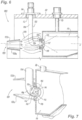
Fig. 7 is a perspective view in partial cross-section of fuel injector assembly ofFig. 6 shown installed in a combustor chamber of a gas turbine engine, and showing a diffuser for guiding compressor airflow towards the air swirler to reduce sparse air feed in general, yet there remains uneven distribution of air flow around the injector and into the air swirler; -
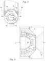
Fig. 8 is a front elevational view of a distal spray tip of an elongated nozzle portion of a nozzle of the fuel injector assembly ofFig. 6 , showing a set of circumferentially spaced apart secondary flat spray slots and a set of circumferentially spaced apart tertiary flat spray slots surrounding a central axis, with fuel issuing therefrom; -
Fig. 9 is an enlarged localized cross-sectional view of the injector assembly ofFig. 6 showing fuel issuing from the secondary flat spray slots, the tertiary flat spray slots, and the primary atomizer port; -
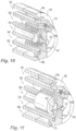
Fig. 10 is a perspective in partial cross-sectional view ofFig. 8 , showing a primary fuel circuit, a secondary fuel circuit, and a tertiary fuel circuit within the distal spray tip of the elongated nozzle portion, and illustrating splash plate style spray slots; and -
Fig. 11 is a perspective in partial cross section view ofFig. 8 , showing the primary fuel circuit, the secondary fuel circuit, and the tertiary fuel circuit within the distal spray tip of the elongated nozzle portion, illustrating pressure washer style spray slots. - Referring now to the drawings wherein like reference numerals identify similar structural features or aspects of the subject disclosure, there is shown in
Fig. 1 , an engine casing designated generally byreference numeral 50, which includes afuel injector assembly 100 constructed in accordance with an embodiment of the subject disclosure that is designed to cover various combustor geometries and provide targeted flat spray. - Referring to
Fig. 1 , thefuel injector assembly 100 includes afuel nozzle 102 having aradial feed arm 104 with an elongated axially extendingnozzle portion 106, which has a central axis "X" extending therethrough. Thefuel nozzle 102 is received within theengine casing 50 through aninlet hole 52 and is secured in place by aninlet fitting 54. Thefuel nozzle 102 is supplied fuel from a fuel supply when in operation. As shown inFig. 1 , when in operation, fuel is sprayed out of theelongated nozzle portion 106 into anair swirler 118 and through to acombustion chamber 56. - With reference to
Fig. 2 , theelongated nozzle portion 106 has a distal spray tip 108 (e.g., as shown inFig. 1 ) with a frusto-conicalouter surface 110 and a planarfront surface 112. A primarypressure atomizer port 114 is centrally provided in the planarfront surface 112 of thedistal spray tip 108 and a set of circumferentially spaced apart secondary flat spray slots 116 (e.g., secondaryflat spray slots 116a-116d, as shown inFig. 3 ) are provided in the frusto-conicalouter surface 110 of thedistal spray tip 108. The secondaryflat spray slots 116 have non-uniform flow rates (e.g., injection characteristic, such as angle, can vary for improvement with uneven air flow). In operation, thepressure atomizing port 114 meters the flow rate of exiting fuel into a conic spray pattern 144, as shown inFig. 4 , and the secondaryflat spray slots 116a-116d create aflat spray pattern 146, as shown inFigs. 3 and 4 . - With continued reference to
Figs. 1 and 2 , thefuel injector assembly 100 further includes anair swirler 118 operatively associated with thedistal spray tip 108. Adiffuser 120 is separate from, but operatively associated with thefuel injector assembly 100 for guiding compressor airflow towards the air swirler. Thediffuser 120 has a radiallyinner wall 120a and a radiallyouter wall 120b, as best shown inFig. 2 . In operation, air flows through thediffuser 120 and surrounds theelongated nozzle portion 106 of thefuel nozzle 102 in an uneven pattern, as indicated by thedirectional flow arrows 148 inFig. 1 . The air flow around theelongated nozzle portion 106, e.g., as shown by the dotted circle inFig. 1 andFig. 6 , surrounding thearrows 148, may have a concentrated air flow region around the center and creates dense and sparse air feed intoair swirler 118. Fuel can be more efficiently placed into the high/low air flow regions by the independent calibration of particular injection sites (e.g.,flat spray slots 116 & 136). For example, the secondaryflat spray slots flat spray slots - In certain embodiments, the
air swirler 118 is an air swirler cup. In certain other embodiments, theair swirler 118 is a dome air swirler. Any other suitable type of air swirler is contemplated herein. InFigs. 1 and 2 , theair swirler 118 is shown within acombustion chamber 56 of the gas turbine engine. It is envisioned that pilot fuel flow from thefuel nozzle 102 can be targeted, for example, directed at theignitor 58 during engine start-up (e.g., as shown inFig. 1 ). - With reference to
Fig. 3 , four secondaryflat spray slots 116a-116d are shown spaced circumferentially around the central axis X. The four secondaryflat spray slots 116a-116d can be spaced apart 90 degrees from each other (e.g., as shown inFig. 3 ), or can include any other suitable arrangement. For example, there can be less than four secondaryflat spray slots 116 or more than for secondaryflat spray slots 116. They can have different arcs and angles than what is shown inFig. 3 . They can be longer or shorter in length and wider or narrower in width than what is shown inFig. 3 . Any suitable length, arc, width, and number of secondaryflat spray slots 116 is contemplated herein. For example, certain secondaryflat spray slots 116 may have a larger flow number and a wider angle resulting in one type of fuel flow pattern, while other secondaryflat spray slots 116 may have a lower flow number and a narrower angle resulting in a different fuel flow pattern. - With continued reference to
Fig. 3 , the secondaryflat spray slots 116a-116d are embedded or otherwise formed within the frusto-conicalouter surface 110. The secondaryflat spray slots 116a-116d are shown with fuel being sprayed therethrough, resulting in theflat spray pattern 146. Each secondaryflat spray slot 116a-116d, can be different as described above, to provide for different flow rates and flow patterns. - Referring to
Fig. 4 , thedistal spray tip 108 is shown within theair swirler 118. Thefuel injector assembly 100 is shown in operation and a fuel spray is shown coming from thepressure atomizer port 114 as well as from the secondaryflat spray slots 116. The fuel coming from the pressure atomizer port is the conic spray pattern 144 and the fuel coming from the secondaryflat spray slots 116a-116d is theflat spray pattern 146. The location of the secondaryflat spray slots 116 around the central axis X (e.g., side versus top versus bottom locations) can each have unique performance characteristics. For example, top and/or bottom location spray slots may be a lower flow number and a narrower angle and side location spray slots may be a larger flow number and wider angle. - Referring now to
Fig. 5 , the primarypressure atomizer port 114 is operatively associated with aprimary pressure atomizer 122 within thedistal spray tip 108 of thenozzle portion 106 of thefuel nozzle 102. Theprimary pressure atomizer 122 is a common pressure atomizer used in the primary (e.g., pilot)fuel circuit 138. Theprimary pressure atomizer 122 includes anatomizing tip portion 124 which the primarypressure atomizer port 114 extends through. Theprimary pressure atomizer 122 further includes afuel swirler 126 surrounded by theatomizing tip portion 124. The fuel swirler 126 has afront surface 128 which abuts aninner wall 130 of theatomizing tip portion 124. The fuel swirler 126 has a plurality of offsetslots 132a, 132b, e.g., as best shown inFig. 10 , and amain swirler 134. The plurality of offsetslots 132a, 132b aid in imparting centrifugal swirling. Any number of offset slots 132 is contemplated herein. The fuel exits the plurality of offsetslots 132a, 132b and is directed into themain swirler 134 by theinner wall 130 of theprimary pressure atomizer 122 and through the primarypressure atomizer port 114. - A primary
fuel supply circuit 138 extends through thefuel nozzle 102 for supplying fuel to the primarypressure atomizer port 114. A secondaryfuel supply circuit 140 extends through thefuel nozzle 102 for supplying fuel to the set of circumferentially spaced apart secondaryflat spray slots 116. Theprimary fuel circuit 138 andsecondary fuel circuit 140 are all supplied fuel independently and can each be staged on and/or off as best suits combustion performance (e.g., for power necessity, burn efficiency, emissions, etc.). - With continued reference to
Figs. 4 and 5 , in one embodiment, each flat spray slot in the set of circumferentially spaced apart secondaryflat spray slots 116 is a splash plate style spray slot (e.g., as shown by the secondary flat spray slots ofFig. 5 ). In another embodiment, each flat spray slot in the set of circumferentially spaced apart secondaryflat spray slots 116 is a pressure washer style spray slot (e.g., a pressure washer style spray slot is shown inFig. 11 for the tertiary flat spray slots 136). The secondaryflat spray slots 116 can be any arrangement of pressure washer and or splash plate style slots. The pressure washer style spray slots may be created by a keyseat, a double angle shank, or thread mill style cutting tool. The splash plate style spray slots may be created by a keyseat style cutting tool. - Each of the
secondary fuel circuits 140 include respective nominally central passages 143, e.g., as shown inFigs. 10, and 11 , which are operatively connected to the secondaryflat spray slots 116. The nominally central passages 143a of the washer pressure washer style spray slots, e.g., as shown inFig 11 ) have an eccentric open area between the nominally central passage 143a and the secondaryflat spray slots 116 to perform flow rate metering of exiting fuel and generates flat fuel spray. The nominally central passages 143b of the splash plate style spray slots, (e.g., as shown inFigs 10 ), can be covered completely or partially by the opposite side of the secondaryflat spray slots 116. The nominally central passage 143b may partially intersect the opposite side of the secondaryflat spray slots 116 without impacting the spray performance. - Referring to
Fig. 6 , the system as described above with respect toFig. 1 is shown including all of the features described above with respect toFigs. 1-5 . InFig. 6 , the fuel injector assembly further includes a set of circumferentially spaced apart tertiaryflat spray slots 136 provided in the frusto-conicalouter surface 110 rearward of the set of circumferentially spaced apart secondaryflat spray slots 116. The tertiaryflat spray slots 136 have non-uniform flow rates (e.g., injection characteristic, such as angle, can vary for improvement with uneven air flow) InFig. 6 , the fuel injector is shown in operation as described above with respect toFig. 1 . Fuel is sprayed out of theelongated nozzle portion 106 into anair swirler 118 and into thecombustion chamber 56. - Referring to
Fig. 7 , theelongated nozzle portion 106 includes the distal spray tip 108 (e.g., as shown inFig. 6 ) with the frusto-conicalouter surface 110 and the planarfront surface 112. The primarypressure atomizer port 114 is centrally provided in the planarfront surface 112 of thedistal spray tip 108 and a set of circumferentially spaced apart secondaryflat spray slots 116 and circumferentially spaced tertiary flat spray slots 136 (e.g., threetertiary spray slots 136a-136c as shown inFig. 8 ) are provided in the frusto-conicalouter surface 110 of thedistal spray tip 108. In operation, thepressure atomizing port 114 meters the flow rate of exiting fuel into a conic spray pattern 144, e.g., as shown inFig. 9 , and the secondaryflat spray slots 116 and tertiaryflat spray slots 136 create aflat spray pattern 146, as shown inFigs. 8 and 9 . - Referring to
Fig. 8 , three secondaryflat spray slots 116a-116c are shown spaced circumferentially around the central axis X and three tertiaryflat spray slots 136a-136c are shown rearward of the secondaryflat spray slots 116a-116c and circumferentially spaced around the central axis X. The three secondaryflat spray slots 116a-116c and the tertiaryflat spray slots 136a-136c can be spaced apart 120 degrees from each other, e.g., as shown inFig 8 , or they can include any other suitable arrangement. For example, there can be less than three secondaryflat spray slots 116 and/or tertiaryflat spray slots 136 or more than three secondaryflat spray slots 116 and/or tertiaryflat spray slots 136. They can have different arcs and angles than what is shown inFig. 8 . They can be longer or shorter in length and wider or narrower in width than what is shown inFig. 8 . Any suitable length, arc, width, and number of secondaryflat spray slots 116 and/or tertiaryflat spray slots 136 is contemplated herein. - In one embodiment, the set of circumferentially spaced apart secondary
flat spray slots 116a-116c and the set of circumferentially spaced apart tertiaryflat spray slots 136a-136c can be axially aligned with one another relative to the central axis X of theelongated nozzle portion 106. For example, each of the secondaryflat spray slots 116a-116c can be spaced apart 120 degrees from each other and each of the tertiaryflat spray slots 136 can be reward of the secondaryflat spray slots 116a-116c and can also be spaced 120 degrees apart from each other. - In another embodiment shown in
Fig. 8 , the set of circumferentially spaced apart secondaryflat spray slots 116a-116c and the set of circumferentially spaced apart tertiaryflat spray slots 136a-136c can be axially offset from one another relative to the central axis X of theelongated nozzle portion 106. For example, the secondaryflat spray slots 116a-116c can be spaced apart 120 degrees from one another around the central axis and the tertiaryflat spray slots 136a-136c can be reward of the secondaryflat spray slots 116a-116c and spaced apart from each other 240 degrees from each other. - With continued reference to
Fig. 8 , the secondaryflat spray slots 116a-116c and tertiaryflat spray slots 136a-136c are embedded within the frusto-conicalouter surface 110. The secondaryflat spray slots 116a-116c and tertiaryflat spray slots 136a-136c are shown with fuel being sprayed therethrough, resulting in theflat spray pattern 146. Each secondaryflat spray slot 116a-116c and tertiaryflat spray slot 136a-136c, can be different as described above, to provide for different flow rates and flow patterns. - Referring now to
Fig. 9 , thedistal spray tip 108 is shown within theair swirler 118. Thefuel injector assembly 100 is shown in operation and a fuel spray is shown coming from thepressure atomizer port 114 as well as from the secondaryflat spray slots 116 and the tertiaryflat spray slots 136. The fuel coming from the pressure atomizer port is the conic spray pattern 144 and the fuel coming from the secondaryflat spray slots 116 and the tertiaryflat spray slots 136 is theflat spray pattern 146. The location of the secondaryflat spray slots 116 and the tertiaryflat spray slots 136 around the central axis X (e.g., side versus top versus bottom locations) can each have unique performance characteristics. For example, top and/or bottom location spray slots may be a lower flow number and a narrower angle and side location spray slots may be a larger flow number and wider angle. - Referring to
Figs. 10 and 11 , a primaryfuel supply circuit 138 extends through thefuel nozzle 102 for supplying fuel to the primarypressure atomizer port 114. A secondaryfuel supply circuit 140 extends through thefuel nozzle 102 for supplying fuel to the set of circumferentially spaced apart secondaryflat spray slots 116. A tertiaryfuel supply circuit 142 extends through thefuel nozzle 102 for supplying fuel to the set of circumferentially spaced apart tertiaryflat spray slots 136. Theprimary fuel circuit 138,secondary fuel circuit 140, andtertiary fuel circuit 142 are all supplied independently and can each be staged on and/or off as best suits combustion performance, e.g., for power necessity, burn efficiency, emissions, etc.). - In one embodiment, each flat spray slot in the set of circumferentially spaced apart secondary
flat spray slots 116 is a splash plate style spray slot. In another embodiment, each flat spray slot in the set of circumferentially spaced apart secondaryflat spray slots 116 is a pressure washer style spray slot. In certain embodiments, each flat spray slot in the set of circumferentially spaced apart tertiaryflat spray slots 136 is a splash plate style spray slot. In other embodiments, each flat spray slot in the set of circumferentially spaced apart tertiaryflat spray slots 136 is a pressure washer style spray slot. As shown inFig. 10 , the tertiaryflat spray slots 136 are of the flat spray style slot. As shown inFig. 11 , the tertiaryflat spray slots 136 are of the pressure washer style spray slot. - The secondary
flat spray slots 116 and tertiaryflat spray slots 136 can be any arrangement of washer and or splash plate style slots. The pressure washer style spray slots may be created by a keyseat, a double angle shank, or thread mill style cutting tool. The splash plate style spray slots may be created by a keyseat style cutting tool. - With continued reference to
Figs. 10 and 11 , each of thesecondary fuel circuits 140 andtertiary fuel circuits 142 include respective nominally central passages 143, e.g., as shown inFigs. 9 and10 , which are operatively connected to the secondaryflat spray slots 116 and the tertiaryflat spray slots 136. The nominally central passages 143a of the washer pressure washer style spray slots have an eccentric open area between the nominally central passage 143a and the secondary flat spray slots 166 and/or the tertiaryflat spray slots 136 to perform flow rate metering of exiting fuel and generates flat fuel spray. The nominally central passages 143b of the splash plate style spray slots can be covered completely or partially by the opposite side of the secondaryflat spray slots 116 and/or the tertiaryflat spray slots 136. The nominally central passage 143b may partially intersect the opposite side of the secondaryflat spray slots 116 and/or the tertiaryflat spray slots 136 without impacting the spray performance. - The embodiments of the present disclosure, as described above and shown in the drawings, provide for improvement in the art to which they pertain.
Claims (15)
- A fuel injector assembly (100) for a gas turbine engine, comprising:
a fuel nozzle (102) including a radial feed arm (104) with an elongated axially extending nozzle portion (106) having a central axis (X) extending therethrough, the elongated nozzle portion having a distal spray tip (108) with a frusto-conical outer surface (110) and a planar front surface (112), wherein a primary pressure atomizer port (114) is centrally provided in the planar front surface of the distal spray tip and a set of circumferentially spaced apart secondary flat spray slots (116) are provided in the frusto-conical outer surface of the distal spray tip. - The fuel injector assembly of claim 1, wherein the primary pressure atomizer port (114) is operatively associated with a primary pressure atomizer (122) within the distal spray tip (108) of the nozzle portion of the fuel nozzle, wherein the primary pressure atomizer includes an atomizing tip portion (124) which the primary pressure atomizer port extends through, and a fuel swirler (126) surrounded by the atomizing tip portion; and optionally:
wherein the fuel swirler has a front surface (128) which abuts an inner wall (130) of the atomizing tip portion, wherein the fuel swirler has a plurality of offset slots (132n) and a main swirler (134), and wherein fuel exits the plurality of offset slots and is directed into the main swirler by the inner wall of the primary pressure atomizer and through the primary pressure atomizer port. - The fuel injector assembly of Claim 1 or 2, wherein a set of circumferentially spaced apart tertiary flat spray slots (136) are provided in the frusto-conical outer surface (110) rearward of the set of circumferentially spaced apart secondary flat spray slots (116).
- The fuel injector assembly of Claim 1, 2 or 3, wherein a primary fuel supply circuit extends through the fuel nozzle (102) for supplying fuel to the primary pressure atomizer port (114); and/or wherein a secondary fuel supply circuit extends through the fuel nozzle for supplying fuel to the set of circumferentially spaced apart secondary flat spray slots (116).
- The fuel injector assembly of Claim 3 or 4, wherein a tertiary fuel supply circuit extends through the fuel nozzle (102) for supplying fuel to the set of circumferentially spaced apart tertiary flat spray slots (136).
- The fuel injector assembly of Claim 3, 4 or 5, wherein the each flat spray slot in the set of circumferentially spaced apart secondary flat spray slots (116) is a splash plate style spray slot; and/or wherein the each flat spray slot in the set of circumferentially spaced apart tertiary flat spray slots (136) is a splash plate style spray slot.
- The fuel injector assembly of any of claims 3 to 6, wherein the each flat spray slot in the set of circumferentially spaced apart secondary flat spray slots (116) is a pressure washer style spray slot; and/or wherein the each flat spray slot in the set of circumferentially spaced apart tertiary flat spray slots (136) is a pressure washer style spray slot.
- The fuel injector assembly of any preceding Claim, wherein the set of circumferentially spaced apart secondary flat spray slots (116) includes at least three circumferentially spaced apart secondary flat spray slots.
- The fuel injector assembly of any of Claims 3 to 8, wherein the set of circumferentially spaced apart tertiary flat spray slots (136) includes at least three circumferentially spaced apart tertiary flat spray slots.
- The fuel injector assembly of any of Claims 3 to 9, wherein the set of circumferentially spaced apart secondary flat spray slots (116) and the set of circumferentially spaced apart tertiary flat spray slots (136) are axially aligned with one another relative to the central axis (X) of the elongated nozzle portion (106).
- The fuel injector assembly of any of Claims 3 to 10, wherein the set of circumferentially spaced apart secondary flat spray slots (116) and the set of circumferentially spaced apart tertiary flat spray slots (136) are axially offset from one another relative to the central axis (X) of the elongated nozzle portion (106).
- The fuel injector assembly of any of Claims 3 to 11, further comprising an air swirler (118) operatively associated with the distal spray tip (106).
- The fuel injector assembly of any preceding claim, wherein the secondary flat spray slots (116) have non-uniform flow rates.
- The fuel injector assembly of Claim 12 or 13, wherein the air swirler (118) is a dome air swirler; or wherein the air swirler (118) is an air swirler cup.
- The fuel injector assembly of any preceding Claim, wherein the primary pressure atomizer port (114) is adapted and configured to issue a conic fuel spray.
Applications Claiming Priority (1)
| Application Number | Priority Date | Filing Date | Title |
|---|---|---|---|
| US18/225,796 US20250035306A1 (en) | 2023-07-25 | 2023-07-25 | Flat spray fuel injectors |
Publications (2)
| Publication Number | Publication Date |
|---|---|
| EP4498000A1 true EP4498000A1 (en) | 2025-01-29 |
| EP4498000B1 EP4498000B1 (en) | 2026-03-18 |
Family
ID=92043041
Family Applications (1)
| Application Number | Title | Priority Date | Filing Date |
|---|---|---|---|
| EP24190964.7A Active EP4498000B1 (en) | 2023-07-25 | 2024-07-25 | Flat spray fuel injectors |
Country Status (2)
| Country | Link |
|---|---|
| US (1) | US20250035306A1 (en) |
| EP (1) | EP4498000B1 (en) |
Families Citing this family (1)
| Publication number | Priority date | Publication date | Assignee | Title |
|---|---|---|---|---|
| US12338774B1 (en) * | 2024-04-11 | 2025-06-24 | General Electric Company | Fuel injector manifold having a variable fuel flow system for a turbine engine |
Citations (6)
| Publication number | Priority date | Publication date | Assignee | Title |
|---|---|---|---|---|
| JPS6197064A (en) * | 1984-10-17 | 1986-05-15 | Toyota Central Res & Dev Lab Inc | Two-fluid spray nozzle |
| JPH0666156A (en) * | 1992-08-11 | 1994-03-08 | Mitsubishi Heavy Ind Ltd | Fuel injection device for gas turbine |
| US5685706A (en) * | 1993-09-15 | 1997-11-11 | Electric Power Research Institute | V-jet atomizer |
| EP1251309A1 (en) * | 2001-04-20 | 2002-10-23 | Combustion Components Associates, Inc. | Fuel oil atomizer and method for discharging atomized fuel oil |
| US20140041390A1 (en) * | 2009-09-18 | 2014-02-13 | Delavan Inc. | Lean burn injectors having multiple pilot circuits |
| EP3832207A1 (en) * | 2019-12-06 | 2021-06-09 | Raytheon Technologies Corporation | Fuel injector assembly |
Family Cites Families (7)
| Publication number | Priority date | Publication date | Assignee | Title |
|---|---|---|---|---|
| JPS4924012B1 (en) * | 1971-03-03 | 1974-06-20 | ||
| US6024301A (en) * | 1998-10-16 | 2000-02-15 | Combustion Components Associates, Inc. | Low NOx liquid fuel oil atomizer spray plate and fabrication method thereof |
| US6547163B1 (en) * | 1999-10-01 | 2003-04-15 | Parker-Hannifin Corporation | Hybrid atomizing fuel nozzle |
| US6523350B1 (en) * | 2001-10-09 | 2003-02-25 | General Electric Company | Fuel injector fuel conduits with multiple laminated fuel strips |
| US10571128B2 (en) * | 2015-06-30 | 2020-02-25 | Ansaldo Energia Ip Uk Limited | Gas turbine fuel components |
| US12326259B2 (en) * | 2020-11-24 | 2025-06-10 | Pratt & Whitney Canada Corp. | Fuel swirler for pressure fuel nozzles |
| US11873993B1 (en) * | 2023-02-02 | 2024-01-16 | Pratt & Whitney Canada Corp. | Combustor for gas turbine engine with central fuel injection ports |
-
2023
- 2023-07-25 US US18/225,796 patent/US20250035306A1/en active Pending
-
2024
- 2024-07-25 EP EP24190964.7A patent/EP4498000B1/en active Active
Patent Citations (6)
| Publication number | Priority date | Publication date | Assignee | Title |
|---|---|---|---|---|
| JPS6197064A (en) * | 1984-10-17 | 1986-05-15 | Toyota Central Res & Dev Lab Inc | Two-fluid spray nozzle |
| JPH0666156A (en) * | 1992-08-11 | 1994-03-08 | Mitsubishi Heavy Ind Ltd | Fuel injection device for gas turbine |
| US5685706A (en) * | 1993-09-15 | 1997-11-11 | Electric Power Research Institute | V-jet atomizer |
| EP1251309A1 (en) * | 2001-04-20 | 2002-10-23 | Combustion Components Associates, Inc. | Fuel oil atomizer and method for discharging atomized fuel oil |
| US20140041390A1 (en) * | 2009-09-18 | 2014-02-13 | Delavan Inc. | Lean burn injectors having multiple pilot circuits |
| EP3832207A1 (en) * | 2019-12-06 | 2021-06-09 | Raytheon Technologies Corporation | Fuel injector assembly |
Also Published As
| Publication number | Publication date |
|---|---|
| US20250035306A1 (en) | 2025-01-30 |
| EP4498000B1 (en) | 2026-03-18 |
Similar Documents
| Publication | Publication Date | Title |
|---|---|---|
| CA2332359C (en) | Gas turbine fuel injector | |
| US6622488B2 (en) | Pure airblast nozzle | |
| US8128007B2 (en) | Radially outward flowing air-blast fuel injector for gas turbine engine | |
| US9046039B2 (en) | Staged pilots in pure airblast injectors for gas turbine engines | |
| KR100542900B1 (en) | Air atomized discrete jet liquid fuel injector and method | |
| US12422142B2 (en) | Fuel injector assembly for a turbine engine | |
| US6578777B2 (en) | Low pressure spray nozzle | |
| US20040061001A1 (en) | Discrete jet atomizer | |
| EP3180565B1 (en) | Multi-functional fuel nozzle with a dual-orifice atomizer | |
| US7117678B2 (en) | Fuel injector head | |
| JP2003106528A (en) | Double injector | |
| EP3180566B1 (en) | Multi-functional fuel nozzle with an atomizer array | |
| US20180304281A1 (en) | Airblast fuel nozzle | |
| EP2592351B1 (en) | Staged pilots in pure airblast injectors for gas turbine engines | |
| EP4498000B1 (en) | Flat spray fuel injectors | |
| JP2017524890A (en) | Multifunctional fuel nozzle with heat shield |
Legal Events
| Date | Code | Title | Description |
|---|---|---|---|
| PUAI | Public reference made under article 153(3) epc to a published international application that has entered the european phase |
Free format text: ORIGINAL CODE: 0009012 |
|
| STAA | Information on the status of an ep patent application or granted ep patent |
Free format text: STATUS: THE APPLICATION HAS BEEN PUBLISHED |
|
| AK | Designated contracting states |
Kind code of ref document: A1 Designated state(s): AL AT BE BG CH CY CZ DE DK EE ES FI FR GB GR HR HU IE IS IT LI LT LU LV MC ME MK MT NL NO PL PT RO RS SE SI SK SM TR |
|
| STAA | Information on the status of an ep patent application or granted ep patent |
Free format text: STATUS: REQUEST FOR EXAMINATION WAS MADE |
|
| 17P | Request for examination filed |
Effective date: 20250728 |
|
| GRAP | Despatch of communication of intention to grant a patent |
Free format text: ORIGINAL CODE: EPIDOSNIGR1 |
|
| STAA | Information on the status of an ep patent application or granted ep patent |
Free format text: STATUS: GRANT OF PATENT IS INTENDED |
|
| INTG | Intention to grant announced |
Effective date: 20251024 |
|
| GRAS | Grant fee paid |
Free format text: ORIGINAL CODE: EPIDOSNIGR3 |
|
| GRAA | (expected) grant |
Free format text: ORIGINAL CODE: 0009210 |
|
| STAA | Information on the status of an ep patent application or granted ep patent |
Free format text: STATUS: THE PATENT HAS BEEN GRANTED |
|
| AK | Designated contracting states |
Kind code of ref document: B1 Designated state(s): AL AT BE BG CH CY CZ DE DK EE ES FI FR GB GR HR HU IE IS IT LI LT LU LV MC ME MK MT NL NO PL PT RO RS SE SI SK SM TR |
|
| REG | Reference to a national code |
Ref country code: CH Ref legal event code: F10 Free format text: ST27 STATUS EVENT CODE: U-0-0-F10-F00 (AS PROVIDED BY THE NATIONAL OFFICE) Effective date: 20260318 Ref country code: GB Ref legal event code: FG4D |
|
| REG | Reference to a national code |
Ref country code: IE Ref legal event code: FG4D |
|
| REG | Reference to a national code |
Ref country code: DE Ref legal event code: R096 Ref document number: 602024003263 Country of ref document: DE |
|
| PG25 | Lapsed in a contracting state [announced via postgrant information from national office to epo] |
Ref country code: RS Free format text: LAPSE BECAUSE OF FAILURE TO SUBMIT A TRANSLATION OF THE DESCRIPTION OR TO PAY THE FEE WITHIN THE PRESCRIBED TIME-LIMIT Effective date: 20260618 |
|
| PG25 | Lapsed in a contracting state [announced via postgrant information from national office to epo] |
Ref country code: GR Free format text: LAPSE BECAUSE OF FAILURE TO SUBMIT A TRANSLATION OF THE DESCRIPTION OR TO PAY THE FEE WITHIN THE PRESCRIBED TIME-LIMIT Effective date: 20260619 |
|
| REG | Reference to a national code |
Ref country code: LT Ref legal event code: MG9D |
|
| PG25 | Lapsed in a contracting state [announced via postgrant information from national office to epo] |
Ref country code: LT Free format text: LAPSE BECAUSE OF FAILURE TO SUBMIT A TRANSLATION OF THE DESCRIPTION OR TO PAY THE FEE WITHIN THE PRESCRIBED TIME-LIMIT Effective date: 20260318 |
|
| PG25 | Lapsed in a contracting state [announced via postgrant information from national office to epo] |
Ref country code: NO Free format text: LAPSE BECAUSE OF FAILURE TO SUBMIT A TRANSLATION OF THE DESCRIPTION OR TO PAY THE FEE WITHIN THE PRESCRIBED TIME-LIMIT Effective date: 20260618 |
|
| PG25 | Lapsed in a contracting state [announced via postgrant information from national office to epo] |
Ref country code: SE Free format text: LAPSE BECAUSE OF FAILURE TO SUBMIT A TRANSLATION OF THE DESCRIPTION OR TO PAY THE FEE WITHIN THE PRESCRIBED TIME-LIMIT Effective date: 20260318 Ref country code: FI Free format text: LAPSE BECAUSE OF FAILURE TO SUBMIT A TRANSLATION OF THE DESCRIPTION OR TO PAY THE FEE WITHIN THE PRESCRIBED TIME-LIMIT Effective date: 20260318 |
|
| PG25 | Lapsed in a contracting state [announced via postgrant information from national office to epo] |
Ref country code: HR Free format text: LAPSE BECAUSE OF FAILURE TO SUBMIT A TRANSLATION OF THE DESCRIPTION OR TO PAY THE FEE WITHIN THE PRESCRIBED TIME-LIMIT Effective date: 20260318 |
|
| REG | Reference to a national code |
Ref country code: NL Ref legal event code: MP Effective date: 20260318 |
|
| PG25 | Lapsed in a contracting state [announced via postgrant information from national office to epo] |
Ref country code: LV Free format text: LAPSE BECAUSE OF FAILURE TO SUBMIT A TRANSLATION OF THE DESCRIPTION OR TO PAY THE FEE WITHIN THE PRESCRIBED TIME-LIMIT Effective date: 20260318 |
|
| PG25 | Lapsed in a contracting state [announced via postgrant information from national office to epo] |
Ref country code: BG Free format text: LAPSE BECAUSE OF FAILURE TO SUBMIT A TRANSLATION OF THE DESCRIPTION OR TO PAY THE FEE WITHIN THE PRESCRIBED TIME-LIMIT Effective date: 20260318 |