EP4497999A1 - Airblast fuel injectors - Google Patents
Airblast fuel injectors Download PDFInfo
- Publication number
- EP4497999A1 EP4497999A1 EP24190934.0A EP24190934A EP4497999A1 EP 4497999 A1 EP4497999 A1 EP 4497999A1 EP 24190934 A EP24190934 A EP 24190934A EP 4497999 A1 EP4497999 A1 EP 4497999A1
- Authority
- EP
- European Patent Office
- Prior art keywords
- fuel
- fuel injector
- feed
- airblast
- air swirler
- Prior art date
- Legal status (The legal status is an assumption and is not a legal conclusion. Google has not performed a legal analysis and makes no representation as to the accuracy of the status listed.)
- Pending
Links
Images



Classifications
-
- F—MECHANICAL ENGINEERING; LIGHTING; HEATING; WEAPONS; BLASTING
- F02—COMBUSTION ENGINES; HOT-GAS OR COMBUSTION-PRODUCT ENGINE PLANTS
- F02M—SUPPLYING COMBUSTION ENGINES IN GENERAL WITH COMBUSTIBLE MIXTURES OR CONSTITUENTS THEREOF
- F02M53/00—Fuel-injection apparatus characterised by having heating, cooling or thermally-insulating means
- F02M53/04—Injectors with heating, cooling, or thermally-insulating means
- F02M53/08—Injectors with heating, cooling, or thermally-insulating means with air cooling
-
- F—MECHANICAL ENGINEERING; LIGHTING; HEATING; WEAPONS; BLASTING
- F23—COMBUSTION APPARATUS; COMBUSTION PROCESSES
- F23R—GENERATING COMBUSTION PRODUCTS OF HIGH PRESSURE OR HIGH VELOCITY, e.g. GAS-TURBINE COMBUSTION CHAMBERS
- F23R3/00—Continuous combustion chambers using liquid or gaseous fuel
- F23R3/02—Continuous combustion chambers using liquid or gaseous fuel characterised by the air-flow or gas-flow configuration
- F23R3/04—Air inlet arrangements
- F23R3/10—Air inlet arrangements for primary air
- F23R3/12—Air inlet arrangements for primary air inducing a vortex
- F23R3/14—Air inlet arrangements for primary air inducing a vortex by using swirl vanes
-
- F—MECHANICAL ENGINEERING; LIGHTING; HEATING; WEAPONS; BLASTING
- F23—COMBUSTION APPARATUS; COMBUSTION PROCESSES
- F23R—GENERATING COMBUSTION PRODUCTS OF HIGH PRESSURE OR HIGH VELOCITY, e.g. GAS-TURBINE COMBUSTION CHAMBERS
- F23R3/00—Continuous combustion chambers using liquid or gaseous fuel
- F23R3/28—Continuous combustion chambers using liquid or gaseous fuel characterised by the fuel supply
- F23R3/283—Attaching or cooling of fuel injecting means including supports for fuel injectors, stems, or lances
Definitions
- the feed tube has three fuel tips, each having a respective reception hole that extends axially through the annular wall of the main body.
- the fuel injector includes an outer heat shield surrounding the feed tube. A stagnant air gap exists between the heat shield and the feed tube.
- the inner air cooler 108 is formed in the rear end wall 114 of the main body portion 106 and includes a plurality of circumferentially spaced apart cooling holes 108a, which are best shown in Fig. 6 .
- the cooling holes 108a surround the central axis X.
- the inner air cooler 108 facilitates cooling of the components of the main body 106 of the annular air swirler 102, particularly the cooling of the conical wall portion 118.
- the inner air swirler 110 is formed in an annular wall 120 of the main body 106, radially outboard from the conical wall portion 118. It includes a plurality of circumferentially spaced apart swirl holes 110a.
- the temperature of the incoming air e.g., compressor discharge air
- the prefilmer 112 is radially outboard from the inner air swirler 110 and it includes a circumferential prefilming surface 112a that extends downstream from the inner air swirler 110.
- the prefilming surface 112a has a circumferential internal fuel passage 113 formed therein, e.g., as best seen in Fig. 3 , (e.g., the circumferential internal fuel passage is a groove and/or recess which allows fuel to spread circumferentially along the prefilming surface 112a).
- the circumferential inner fuel passage shelters the fuel briefly from the air issuing from inner air swirler 110 allowing the fuel to distribute circumferentially around the prefilmer 112 before it meets with high velocity air issued from the inner air swirler 110.
- a feed tube 122 that has three fuel tips 124 (e.g., each of the fuel tips 124 are shown from an upstream position and are within respective reception holes).
- fuel tips 124 can be incorporated into the annular air swirler to increase the fuel distribution within the annular air swirler 102.
- the multiple fuel tips 124 have separate inlet fuel circuits which can each have different flow rates.
- Each fuel tip 124 has a respective reception hole 126 that extends axially through the annular wall 120 of the main body 106.
- the fuel injector 104 includes an outer heat shield 132 surrounding the feed tube 122.
- a stagnant air gap 134 exists between the heat shield 132 and the feed tube 122, as best seen in Fig. 2 .
- the heat shield 132 is closely fit to the annular air swirler 102 to reduce vibrational stress and wear on the feed tube 122.
- the stagnant air gap 134 isolates the feed tube 122 from high velocity hot air.
- the stagnant air gap 134 limits the amount of heat into the fuel circuit to prevent excessive internal wall temperatures.
- the stagnant air gap 134 prevents high temperatures from causing the fuel to degrade and cause internal carbon within the fuel passages and deteriorate performance.
- the airblast fuel injector assembly 100 further includes an outer air cap 136 surrounding the annular air swirler 102 so as define an outer air passage 138 between the prefilmer 112 and the outer air cap 136.
- the outer air cap 136 can be connected to the annular air swirler 102.
- the outer air passage 138 can be defined by a traditional air cap brazed onto outer air vanes, e.g., straight or swirl vanes, drilled holes, sliding alignment standoffs, or any other suitable manner of making airblast injectors.
- the outer air cap 136 can be formed integral with the annular air swirler 102, e.g., as one machined piece.
- the outer air cap 136 is attached to a combustor liner 140, e.g., as shown in Figs. 1 and 4-5 , of the gas turbine engine, either directly, e.g., by way of vanes, using a floating collar, or by way of a burner seal.
- the reception hole 126 in the annular wall 120 of the main body 106 has a lead-in chamfer or fillet 115 which allows the fuel tip 124 to be easily inserted therein (e.g., as best shown in Fig. 4A ).
- the above described airblast fuel injector assembly 100 reduces the surface area of the fuel circuit and limits heat transfer into the fuel.
- the feed tube 122 and annular air swirler 102 components reduce the overall cost and part count of the assembly.
- the arrangement of the fuel injector assembly 100 allows for easy replacement of the feed tubes 122.
- a fuel injector array 200 for a gas turbine engine configured for multipoint fuel injection which includes a plurality of airblast fuel injector assemblies 100, as described above.
- a grouping or set of annular air swirlers 102a-102j is fed fuel from respective feed tubes 122a-122j by way of respective fuel tips 124a-124j.
- the plurality of feed tubes 122a-122j are connected together along a common feed arm 242.
- each fuel injector array 200 can include ten fuel injector tips 124, or any other suitable number of fuel injector tips or arrangement.
- the fuel is then injected into the air blast injector assembly 100, which creates a film of fuel and is burned with the air to produce heat for the gas turbine engine.
- an array 200 can include seven or eight fuel tips 124 and air swirler assemblies 100, which provides the advantage of shorter feed tubes 122, thereby reducing stress, e.g., as shown by arrays 700 and 800 in Fig. 8 .
- the arrays can be arranged in a manner which results in a smaller casing inlet hole 152 in the gas turbine engine case 150 for the array to be removed (e.g., a five-fuel tip array that is arranged vertically, e.g., as shown by array 600 in Fig. 8 ).
- Each array 200 within a gas turbine engine casing can be uniform or alternatively, each array can have different arrangements entirely.
- the fuel injector array 200 further includes a scheduling valve 244 operatively associated with the fuel injector flange 154 of the feed arm 242 for allowing fuel to feed into different groups of feed tubes 122a-122j at different points of engine operation.
- the scheduling valve 244 is located near the inlet of the fuel injector feed tube 122. The scheduling valve 244 allows the fuel to enter different stages at different points of engine operation.
- each scheduling valve 244 is integral with the fuel injector assembly and attached in place to the gas turbine engine case 150 using the fuel injector flange 154.
- each array allows for the feed tubes 122a-122j to easily be replaced, maintained, and repaired, for example, in the event of internal fuel growth or reduced durability due to thermal erosion or fretting.
- the internal fuel scheduling vale 244 can allow for fuel staging for operability and injector arrays to be fed from a single external fuel manifold.
Landscapes
- Engineering & Computer Science (AREA)
- Chemical & Material Sciences (AREA)
- Combustion & Propulsion (AREA)
- Mechanical Engineering (AREA)
- General Engineering & Computer Science (AREA)
- Fuel-Injection Apparatus (AREA)
Abstract
Description
- This disclosure relates to fuel injectors and more particularly to airblast fuel injector assemblies and line-replaceable multipoint injector arrays for gas turbine engines.
- There is a need for improved thermal isolation of the fuel circuits within fuel injectors for gas turbine engines. The thermal environment that the injectors reside in continues to increase. The temperature of incoming fuel to injectors is also increasing. Improved thermal management is necessary to protect the fuel from overheating, which causes the fuel to deteriorate and can potentially form carbon deposits within the fuel circuit.
- Airblast injectors have many advantages over pressure atomizer fuel injectors, however even with heat shielding, airblast injectors have a larger fuel circuit surface area exposed to high temperatures. This larger surface area makes it harder to design the fuel injectors to withstand the thermal load and protect the fuel from coking.
- Multipoint injection schemes have been shown to reduce engine emissions and improve temperature distribution among other advantages. However, it is difficult to distribute fuel to a large number of fuel injectors. Traditional approaches have included internal fuel manifolds, however the problem exists that internal fuel manifolds are not line replaceable for maintenance, such as cleaning or replacement for durability. Traditional methods would require a major engine overhaul to be able to extract an internal fuel manifold. It would be advantageous for fuel injectors to be line-replaceable.
- Such conventional methods and systems have generally been considered satisfactory for their intended purpose. However, there is still a need in the art for improved thermal management within airblast injectors as well as multipoint injection schemes that are line-replaceable. The present disclosure provides a solution for this need.
- The subject disclosure is directed to a new and useful airblast fuel injector assembly for a gas turbine engine. The airblast fuel injector has an annular air swirler with a main body having a rear end wall defining a central axis of the annular air swirler, and a radially outwardly expanding conical wall portion extending downstream from the rear end wall. The annular air swirler further includes an inner air cooler formed in the rear end wall of the main body portion. The inner air cooler can further include a plurality of circumferentially spaced apart cooling holes surrounding the central axis of the air swirler.
- The annular air swirler further includes an inner air swirler formed in an annular wall of the main body radially outboard from the conical wall portion. The inner air swirler can further include a plurality of circumferentially spaced apart swirl holes. There is a prefilmer radially outboard from the inner air swirler and it includes a circumferential prefilming surface extending downstream from the inner air swirler, wherein the prefilming surface has a circumferential internal fuel passage formed therein. The circumferential inner fuel passage shelters the fuel briefly from the air issuing from inner air swirler allowing the fuel to distribute circumferentially around the prefilmer before it meets with high velocity air issued from the inner air swirler.
- The airblast fuel injector assembly further includes a fuel injector with a feed tube having at least one fuel tip projecting through a respective reception hole formed in the annular wall of the main body radially outboard from the inner air swirler, wherein each fuel tip has a fuel port positioned to direct fuel tangentially into the internal fuel passage in the prefilming surface.
- In one embodiment, the reception holes extend axially through the annular wall of the main body. In another embodiment, the reception holes extend radially through the annular wall of the main body.
- In certain embodiments of the disclosure, the feed tube has three fuel tips, each having a respective reception hole that extends axially through the annular wall of the main body. In certain embodiments, the fuel injector includes an outer heat shield surrounding the feed tube. A stagnant air gap exists between the heat shield and the feed tube.
- In certain embodiments, the airblast fuel injector assembly further includes an outer air cap surrounding the annular air swirler so as to define an outer air passage between the prefilmer and the outer air cap. In certain embodiments, the outer air cap is connected to the annular air swirler. In certain embodiments, the outer air cap is formed integral with the annular air swirler. The outer air cap is attached to a combustor liner of the gas turbine engine either directly, using a floating collar, or by way of a burner seal. In certain embodiments, the reception hole in the annular wall of the main body has a lead-in chamfer or fillet which allows the fuel tip to be easily inserted therein.
- The subject disclosure is also directed to a fuel injector array for a gas turbine engine which is configured for multipoint fuel injection and includes a plurality of airblast fuel injector assemblies as described above. The annular air swirler of each airblast fuel injector assembly is fed fuel from a respective feed tube. A plurality of feed tubes are connected together along a common feed arm.
- In certain embodiments, the fuel injector array further includes a scheduling valve operatively associated with an inlet fitting of the feed arm for allowing fuel to feed into different groups of feed tubes connected to the feed arm at different points of engine operation. The scheduling valve is adapted and configured to allow fuel to feed into a first group of feed tubes during an ignition stage. The scheduling valve is also adapted and configured to allow fuel to feed into a second group of feed tubes during an idle stage. The scheduling valve is also adapted and configured to allow fuel to feed into a third group of feed tubes during high power conditions, for example, a cruise and/or takeoff stage.
- In certain embodiments the fuel injector array includes a thermal management system that defines a cooling loop through the common the feed arm. In addition, the feed tubes and the common feed arm are all surrounded by respective outer heat shields. These and other features of the embodiments of the subject disclosure will become more readily apparent to those skilled in the art from the following detailed description taken in conjunction with the drawings.
- So that those skilled in the art to which the subject disclosure appertains will readily understand how to make and use the devices and methods of the subject disclosure without undue experimentation, embodiments thereof will be described in detail herein below with reference to certain figures, wherein:
-
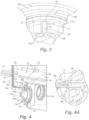
Fig. 1 is a perspective view in cross-section of an engine casing of a gas turbine engine illustrating an airblast fuel injector assembly of the subject disclosure in an installed position; -
Fig. 2 is a side elevational view in cross-section of the airblast fuel injector assembly ofFig. 1 , showing a fuel injector axially inserted into an annular wall of a main body of an annular air swirler; -
Fig. 3 is an enlarged localized perspective view of the airblast fuel injector assembly ofFig. 1 , showing a fuel tip of a feed tube of the fuel injector projecting through a respective reception hole formed in the annular wall of the main body; -
Fig. 4 is a perspective view similar toFig. 1 , wherein the fuel injector feed arm is inserted radially into the engine casing and axially into the respective reception hole formed in the annular wall of the main body of the annular air swirler; -
Fig. 4A is an enlarged localized perspective view of the airblast injector assembly ofFig 1 , showing a lead in chamfer/fillet within a reception hole of the annular air swirler; -
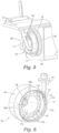
Fig. 5 is a perspective view of an embodiment of an airblast fuel injector assembly which includes three feed tubes inserted within respective reception holes formed in the annular wall of the main body of the annular air swirler; -
Fig. 6 is a perspective view of an embodiment of an airblast injector assembly in accordance with the subject disclosure, wherein the fuel tip is inserted radially in a respective reception hole within the annular wall of the main body of the annular air swirler; -
Fig. 7 is a perspective view of a section of an engine casing of a gas turbine engine configured for multipoint fuel injection which includes an array of airblast fuel injector assemblies of the subject disclosure and wherein a common feed arm supplies fuel to a plurality of feed tubes; -
Fig. 8 is a front elevational view of the section of an engine casing of a gas turbine engine configured for multipoint fuel injection which includes an array of airblast fuel injector assemblies ofFig. 7 , illustrating different feed arm arrangements each configured to feed fuel to a different number of airblast injector assemblies; and -
Fig. 9 is perspective view of the fuel injector of the airblast fuel injector assembly ofFig. 1 , showing a fuel port a fuel tip of the fuel injector. - Referring now to the drawings wherein like reference numerals identify similar structural features or aspects of the subject disclosure, there is shown in
Fig. 1 an engine casing designated generally byreference numeral 150, which includes a plurality of airblastfuel injector assemblies 100 constructed in accordance with an embodiment of the subject disclosure that is designed to improve thermal isolation within a gas turbine engine. - With reference to
Figs. 1 and 2 , an airblastfuel injector assembly 100 includes anannular air swirler 102 and afuel injector 104. Theannular air swirler 102 can be one machined or cast component or an assembly of separate components that are joined together. Theannular air swirler 102 includes amain body 106, aninner air cooler 108, aninner air swirler 110, and aprefilmer 112. Themain body 106 has arear end wall 114 defining a central axis "X" of theannular air swirler 110, and a radially outwardly expandingconical wall portion 118 that extends downstream from therear end wall 114. - With continuing reference to
Fig. 2 , theinner air cooler 108 is formed in therear end wall 114 of themain body portion 106 and includes a plurality of circumferentially spaced apart coolingholes 108a, which are best shown inFig. 6 . Thecooling holes 108a surround the central axis X. Theinner air cooler 108 facilitates cooling of the components of themain body 106 of theannular air swirler 102, particularly the cooling of theconical wall portion 118. Theinner air swirler 110 is formed in anannular wall 120 of themain body 106, radially outboard from theconical wall portion 118. It includes a plurality of circumferentially spaced apart swirlholes 110a. The temperature of the incoming air, e.g., compressor discharge air, is hot enough to burn off residual carbon that may grow on the air swirler at most conditions (e.g., takeoff and cruise). Theprefilmer 112 is radially outboard from theinner air swirler 110 and it includes acircumferential prefilming surface 112a that extends downstream from theinner air swirler 110. Theprefilming surface 112a has a circumferentialinternal fuel passage 113 formed therein, e.g., as best seen inFig. 3 , (e.g., the circumferential internal fuel passage is a groove and/or recess which allows fuel to spread circumferentially along theprefilming surface 112a). The circumferential inner fuel passage shelters the fuel briefly from the air issuing frominner air swirler 110 allowing the fuel to distribute circumferentially around theprefilmer 112 before it meets with high velocity air issued from theinner air swirler 110. - With reference to
Figs. 2 and3 , thefuel injector 104 includes afeed tube 122 which can have at least onefuel tip 124 projecting through arespective reception hole 126 formed in theannular wall 120 of themain body 106, radially outboard from theinner air swirler 110. Eachfuel tip 124 has afuel port 130 positioned to direct fuel tangentially into theinternal fuel passage 113 in theprefilming surface 112a (see alsoFig. 9 ). Thefuel tip 124 andfeed tube 122 can be one machined piece or they can be separately formed and joined together with conventional means such as by brazing or the like. - With reference to
Fig. 3 , thefeed tube 122 is shown in an installed position, inserted within thereception hole 126. Thefuel tip 124 is shown axially aligned with theprefilming surface 112a. In this embodiment, the reception holes 126 extend axially through theannular wall 120 of themain body 106, so that the fuel flows tangentially into the circumferentialinternal fuel passage 113 in theprefilming surface 112a. In another embodiment shown inFig. 6 , the reception holes 126 extend radially through theannular wall 120 of themain body 106, so that the fuel flows tangentially into the circumferentialinternal fuel passage 113 in theprefilming surface 112a. - With reference to
Fig. 4 , thefuel injector 104 is installed by radially inserting thefuel injector 104 into a gasturbine engine case 150. As shown bydirectional arrow 158 inFig. 4 , thefuel injector 104 is radially inserted through anouter wall 156 of the engine casing and through acasing inlet hole 152.Fuel injector flange 154 seals air pressure withing theengine case 150. Once thefuel injector 104 is inserted radially into theengine casing 150, it is then inserted axially into thereception hole 126 of theairblast assembly 102, as shown bydirectional arrow 160 inFig. 4 . Thefuel tip 124 is aligned with thereception hole 126, and thefuel injector 104 axially slides forward into thereception hole 126, thereby engaging thefuel tip 124 within theannular air swirler 102. Thefeed tube 122 of thefuel injector 104 is removed from thereception hole 126 just as it is inserted, facilitating ease of replacement of the part, without having to deconstruct the engine. - The
main body 106 of theannular air swirler 102 is configured to rotate within the floatingcollar 128, in order to align the fuelinjector feed tube 122 with thereception hole 126 for easier insertion. Thefuel injector 104 is welded directly to theengine case 150 by way of flange seals, for example. - With reference to
Fig. 5 , there is illustrated afeed tube 122 that has three fuel tips 124 (e.g., each of thefuel tips 124 are shown from an upstream position and are within respective reception holes). Those skilled in the art will readily appreciate that various numbers offuel tips 124 can be incorporated into the annular air swirler to increase the fuel distribution within theannular air swirler 102. Themultiple fuel tips 124 have separate inlet fuel circuits which can each have different flow rates. There can be separate fuel circuits, e.g., pilot and main fuel, for example, into thesame fuel injector 104. Eachfuel tip 124 has arespective reception hole 126 that extends axially through theannular wall 120 of themain body 106. - Preferably, the
fuel injector 104 includes anouter heat shield 132 surrounding thefeed tube 122. Astagnant air gap 134 exists between theheat shield 132 and thefeed tube 122, as best seen inFig. 2 . Theheat shield 132 is closely fit to theannular air swirler 102 to reduce vibrational stress and wear on thefeed tube 122. Thestagnant air gap 134 isolates thefeed tube 122 from high velocity hot air. Thestagnant air gap 134 limits the amount of heat into the fuel circuit to prevent excessive internal wall temperatures. Thestagnant air gap 134 prevents high temperatures from causing the fuel to degrade and cause internal carbon within the fuel passages and deteriorate performance. - In certain embodiments, the airblast
fuel injector assembly 100 further includes anouter air cap 136 surrounding theannular air swirler 102 so as define anouter air passage 138 between theprefilmer 112 and theouter air cap 136. In certain embodiments, theouter air cap 136 can be connected to theannular air swirler 102. Theouter air passage 138 can be defined by a traditional air cap brazed onto outer air vanes, e.g., straight or swirl vanes, drilled holes, sliding alignment standoffs, or any other suitable manner of making airblast injectors. In certain embodiments, theouter air cap 136 can be formed integral with theannular air swirler 102, e.g., as one machined piece. Theouter air cap 136 is attached to acombustor liner 140, e.g., as shown inFigs. 1 and4-5 , of the gas turbine engine, either directly, e.g., by way of vanes, using a floating collar, or by way of a burner seal. In certain embodiments, thereception hole 126 in theannular wall 120 of themain body 106 has a lead-in chamfer orfillet 115 which allows thefuel tip 124 to be easily inserted therein (e.g., as best shown inFig. 4A ). - In certain embodiments, the above described airblast
fuel injector assembly 100 reduces the surface area of the fuel circuit and limits heat transfer into the fuel. Thefeed tube 122 andannular air swirler 102 components reduce the overall cost and part count of the assembly. The arrangement of thefuel injector assembly 100 allows for easy replacement of thefeed tubes 122. - With reference to
Figs. 7 and8 , there is illustrated afuel injector array 200 for a gas turbine engine configured for multipoint fuel injection, which includes a plurality of airblastfuel injector assemblies 100, as described above. By way of example, a grouping or set ofannular air swirlers 102a-102j is fed fuel fromrespective feed tubes 122a-122j by way of respective fuel tips 124a-124j. The plurality offeed tubes 122a-122j are connected together along acommon feed arm 242. By way of example, eachfuel injector array 200 can include tenfuel injector tips 124, or any other suitable number of fuel injector tips or arrangement. The fuel is then injected into the airblast injector assembly 100, which creates a film of fuel and is burned with the air to produce heat for the gas turbine engine. - With continued reference to
Figs. 7 and8 , anarray 200 can include seven or eightfuel tips 124 andair swirler assemblies 100, which provides the advantage ofshorter feed tubes 122, thereby reducing stress, e.g., as shown byarrays Fig. 8 . The arrays can be arranged in a manner which results in a smallercasing inlet hole 152 in the gasturbine engine case 150 for the array to be removed (e.g., a five-fuel tip array that is arranged vertically, e.g., as shown byarray 600 inFig. 8 ). Eacharray 200 within a gas turbine engine casing can be uniform or alternatively, each array can have different arrangements entirely. - In certain embodiments, the
fuel injector array 200 further includes ascheduling valve 244 operatively associated with thefuel injector flange 154 of thefeed arm 242 for allowing fuel to feed into different groups offeed tubes 122a-122j at different points of engine operation. Thescheduling valve 244 is located near the inlet of the fuelinjector feed tube 122. Thescheduling valve 244 allows the fuel to enter different stages at different points of engine operation. - For example, the
scheduling valve 244 may be adapted and configured to allow fuel to feed into a first group offeed tubes 122 during an ignition stage, e.g., through airblastfuel injector assemblies 102a-102c ofFig. 7 . Thescheduling valve 244 may be further adapted and configured to allow fuel to feed into a second group offeed tubes 122 during an idle stage, e.g., through airblastfuel injector assemblies 102d-102g inFig. 7 . Thescheduling valve 244 may also be adapted and configured to allow fuel to feed into a third group offeed tubes 122 during a cruise and/or takeoff stage, e.g., through airblastfuel injector assemblies 102h-102j. - In certain embodiments the
fuel injector array 200 further includes athermal management system 248. Thethermal management system 248 includes acooling loop 250 through thecommon feed arm 242. Thethermal management system 248 is included by using the pilot fuel stage flow in proximity to the other fuel stages. This allows the pilot fuel which is continuously flowing with cool fuel to keep the other fuel elements cool, even when their fuel is not flowing. Depending on the cooling needed, the pilot fuel can be primarily in thefeed tubes 122a-122j or it can cool all the way to the fuel tips 124a-124j (e.g., each of the fuel tips 124a-124j are shown from an upstream position and are within respective reception holes). Once the pilot fuel is delivered either to the main part of eachfeed tube 122a-122j or to each fuel tip 124a-1224j, it then returns to be injected into the pilot stage annular air swirlers 102a-102j. - In certain embodiments, the plurality of
feed tubes 122a-122j and thecommon feed arm 242 are all be surrounded by respectiveouter heat shields 132, each forming respectivestagnant air gaps 134 as described above. In certain embodiments, eachscheduling valve 244 is integral with the fuel injector assembly and attached in place to the gasturbine engine case 150 using thefuel injector flange 154. - In certain embodiments, the arrangement of each array allows for the
feed tubes 122a-122j to easily be replaced, maintained, and repaired, for example, in the event of internal fuel growth or reduced durability due to thermal erosion or fretting. The internalfuel scheduling vale 244 can allow for fuel staging for operability and injector arrays to be fed from a single external fuel manifold.
Claims (15)
- An airblast fuel injector assembly for a gas turbine engine comprising:a) an annular air swirler (102) including:i) a main body (106) having a rear end wall (114) defining a central axis (X) of the annular air swirler, and a radially outwardly expanding conical wall portion (118) extending downstream from the rear end wall;ii) an inner air cooler (108) formed in the rear end wall of the main body portion;iii) an inner air swirler (110) formed in an annular wall (120) of the main body radially outboard from the conical wall portion;iv) a prefilmer (112) radially outboard from the inner air swirler and including a circumferential prefilming surface extending downstream from the inner air swirler, wherein the prefilming surface has a circumferential internal fuel passage formed therein;b) a fuel injector (104) including a feed tube (122) having at least one fuel tip (124) projecting through a respective reception hole (126) formed in the annular wall of the main body radially outboard from the inner air swirler, each fuel tip having a fuel port (130) positioned to direct fuel tangentially into the internal fuel passage in the prefilming surface.
- The airblast fuel injector assembly of Claim 1, wherein the inner air cooler (108) includes a plurality of circumferentially spaced apart cooling holes (108a) surrounding the central axis; and/or wherein the inner air swirler (110) includes a plurality of circumferentially spaced apart swirl holes (110a).
- The airblast fuel injector assembly of Claim 1 or 2, wherein the reception holes (126) extend axially through the annular wall of the main body (106); or wherein the reception holes extend radially through the annular wall (120) of the main body.
- The airblast fuel injector assembly of Claim 1, 2 or 3, wherein the feed tube (122) has a plurality of fuel tips (124) each having a respective reception hole (126) that extends axially through the annular wall (120) of the main body (106).
- The airblast fuel injector assembly of any preceding Claim, wherein the fuel injector (104) includes an outer heat shield (132) surrounding the feed tube (122), and wherein a stagnant air gap (134) exists between the heat shield and the feed tube.
- The airblast fuel injector assembly of any preceding Claim, further comprising an outer air cap (136) surrounding the annular air swirler (102) so as define an outer air passage (138) between the prefilmer (112) and the outer air cap.
- The airblast fuel injector assembly of Claim 6, wherein the outer air cap (136) is connected to the annular air swirler (102); or wherein the outer air cap (136) is formed integral with the annular air swirler; or wherein the outer air cap is attached to a combustor liner (140) of the gas turbine engine either directly, using a floating collar or by way of a burner seal.
- The airblast fuel injector assembly of any preceding Claim, wherein the reception hole (126) in the annular wall (120) of the main body (106) has a lead-in chamfer or fillet (115) which allows the fuel tip (124) to be easily inserted therein.
- A fuel injector array for a gas turbine engine configured for multipoint fuel injection comprising:
a plurality of airblast fuel injector assemblies as recited in any preceding Claim, wherein the annular air swirler (102a-j) of each airblast fuel injector assembly is fed fuel from a respective feed tube (122a-j), and wherein a plurality of feed tubes are connected together along a common feed arm (242). - A fuel injector array as recited in Claim 9, further comprising a scheduling valve (244) operatively associated with an inlet fitting of the feed arm (242) for allowing fuel to feed into different groups of feed tubes (122a-j) connected to the feed arm at different points of engine operation.
- A fuel injector array as recited in Claim 10, wherein the scheduling valve (244) is adapted and configured to allow fuel to feed into a first group of feed tubes during an ignition stage.
- A fuel injector array as recited in Claim 10, wherein the scheduling valve (244) is adapted and configured to allow fuel to feed into a second group of feed tubes during an idle stage.
- A fuel injector array as recited in Claim 10, wherein the scheduling valve (244) is adapted and configured to allow fuel to feed into a third group of feed tubes during a cruise and/or takeoff stage.
- A fuel injector array as recited in any of Claims 10 to 13, further comprising a thermal management system (248) including a cooling loop (250) through the common the feed arm.
- A fuel injector array as recited in any of Claims 10 to 14, wherein the plurality of feed tubes (122a-j) and the common feed arm (242) are all surrounded by respective outer heat shields.
Applications Claiming Priority (1)
| Application Number | Priority Date | Filing Date | Title |
|---|---|---|---|
| US18/225,844 US12601319B2 (en) | 2023-07-25 | 2023-07-25 | Airblast fuel injectors |
Publications (1)
| Publication Number | Publication Date |
|---|---|
| EP4497999A1 true EP4497999A1 (en) | 2025-01-29 |
Family
ID=92043369
Family Applications (1)
| Application Number | Title | Priority Date | Filing Date |
|---|---|---|---|
| EP24190934.0A Pending EP4497999A1 (en) | 2023-07-25 | 2024-07-25 | Airblast fuel injectors |
Country Status (2)
| Country | Link |
|---|---|
| US (1) | US12601319B2 (en) |
| EP (1) | EP4497999A1 (en) |
Citations (6)
| Publication number | Priority date | Publication date | Assignee | Title |
|---|---|---|---|---|
| US3912164A (en) * | 1971-01-11 | 1975-10-14 | Parker Hannifin Corp | Method of liquid fuel injection, and to air blast atomizers |
| US4327547A (en) * | 1978-11-23 | 1982-05-04 | Rolls-Royce Limited | Fuel injectors |
| US5020329A (en) * | 1984-12-20 | 1991-06-04 | General Electric Company | Fuel delivery system |
| US20070163263A1 (en) * | 2006-01-17 | 2007-07-19 | Goodrich - Delavan Turbine Fuel Technologies | System and method for cooling a staged airblast fuel injector |
| EP3156732A1 (en) * | 2015-10-16 | 2017-04-19 | Delavan, Inc. | Airblast injectors |
| US20190309949A1 (en) * | 2018-04-10 | 2019-10-10 | Delavan Inc. | Fuel injectors for turbomachines having inner air swirling |
Family Cites Families (13)
| Publication number | Priority date | Publication date | Assignee | Title |
|---|---|---|---|---|
| US4216652A (en) | 1978-06-08 | 1980-08-12 | General Motors Corporation | Integrated, replaceable combustor swirler and fuel injector |
| US5873237A (en) | 1997-01-24 | 1999-02-23 | Westinghouse Electric Corporation | Atomizing dual fuel nozzle for a combustion turbine |
| US7628019B2 (en) * | 2005-03-21 | 2009-12-08 | United Technologies Corporation | Fuel injector bearing plate assembly and swirler assembly |
| FR2911667B1 (en) * | 2007-01-23 | 2009-10-02 | Snecma Sa | FUEL INJECTION SYSTEM WITH DOUBLE INJECTOR. |
| US8286433B2 (en) | 2007-10-26 | 2012-10-16 | Solar Turbines Inc. | Gas turbine fuel injector with removable pilot liquid tube |
| US8313046B2 (en) * | 2009-08-04 | 2012-11-20 | Delavan Inc | Multi-point injector ring |
| US8776529B2 (en) * | 2010-09-27 | 2014-07-15 | Hamilton Sundstrand Corporation | Critical flow nozzle for controlling fuel distribution and burner stability |
| US9228741B2 (en) * | 2012-02-08 | 2016-01-05 | Rolls-Royce Plc | Liquid fuel swirler |
| US9644844B2 (en) * | 2011-11-03 | 2017-05-09 | Delavan Inc. | Multipoint fuel injection arrangements |
| US20130219911A1 (en) * | 2012-02-28 | 2013-08-29 | Honeywell International Inc. | Combustion system for a gas turbine engine and method for directing fuel flow within the same |
| US9791153B2 (en) | 2015-02-27 | 2017-10-17 | United Technologies Corporation | Line replaceable fuel nozzle apparatus, system and method |
| CA2955613A1 (en) * | 2016-01-28 | 2017-07-28 | Rolls-Royce North American Technologies, Inc. | Heat exchanger integrated with fuel nozzle |
| US11131458B2 (en) | 2018-04-10 | 2021-09-28 | Delavan Inc. | Fuel injectors for turbomachines |
-
2023
- 2023-07-25 US US18/225,844 patent/US12601319B2/en active Active
-
2024
- 2024-07-25 EP EP24190934.0A patent/EP4497999A1/en active Pending
Patent Citations (6)
| Publication number | Priority date | Publication date | Assignee | Title |
|---|---|---|---|---|
| US3912164A (en) * | 1971-01-11 | 1975-10-14 | Parker Hannifin Corp | Method of liquid fuel injection, and to air blast atomizers |
| US4327547A (en) * | 1978-11-23 | 1982-05-04 | Rolls-Royce Limited | Fuel injectors |
| US5020329A (en) * | 1984-12-20 | 1991-06-04 | General Electric Company | Fuel delivery system |
| US20070163263A1 (en) * | 2006-01-17 | 2007-07-19 | Goodrich - Delavan Turbine Fuel Technologies | System and method for cooling a staged airblast fuel injector |
| EP3156732A1 (en) * | 2015-10-16 | 2017-04-19 | Delavan, Inc. | Airblast injectors |
| US20190309949A1 (en) * | 2018-04-10 | 2019-10-10 | Delavan Inc. | Fuel injectors for turbomachines having inner air swirling |
Also Published As
| Publication number | Publication date |
|---|---|
| US20250035079A1 (en) | 2025-01-30 |
| US12601319B2 (en) | 2026-04-14 |
Similar Documents
| Publication | Publication Date | Title |
|---|---|---|
| US10690350B2 (en) | Combustor with axially staged fuel injection | |
| EP3382280B1 (en) | Fuel injectors for multipoint arrays | |
| US9267436B2 (en) | Fuel distribution manifold for a combustor of a gas turbine | |
| CN104061595B (en) | Continuous burning bushing for the burner of combustion gas turbine | |
| KR102325910B1 (en) | Split Annular Combustion System Using Axial Fuel Staging | |
| US10982853B2 (en) | W501D5/D5A DF42 combustion system | |
| US9574498B2 (en) | Internally cooled transition duct aft frame with serpentine cooling passage and conduit | |
| US8528839B2 (en) | Combustor nozzle and method for fabricating the combustor nozzle | |
| CN113864821B (en) | Improved fuel circuit for fuel injectors | |
| US11156362B2 (en) | Combustor with axially staged fuel injection | |
| CN104344426A (en) | System for providing fuel to a combustor | |
| EP3312508B1 (en) | Gas turbine combustor | |
| CN113864818B (en) | Combustor air flow path | |
| US10612784B2 (en) | Nozzle assembly for a dual-fuel fuel nozzle | |
| KR20250132477A (en) | Gas turbine combustor having multiple fuel stages and method of operation | |
| US20180087776A1 (en) | Mounting assembly for gas turbine engine fluid conduit | |
| KR20250129673A (en) | Method for operating a gas turbine combustor having multiple fuel stages | |
| GB2441342A (en) | Wall Elements for Gas Turbine Engine Components | |
| US10612775B2 (en) | Dual-fuel fuel nozzle with air shield | |
| US12601319B2 (en) | Airblast fuel injectors | |
| US20220404020A1 (en) | Combustor having fuel sweeping structures | |
| EP4488582A1 (en) | Fuel injection assembly for a combustor | |
| US10663171B2 (en) | Dual-fuel fuel nozzle with gas and liquid fuel capability | |
| EP4067746B1 (en) | Combustor having a wake energizer | |
| US10955141B2 (en) | Dual-fuel fuel nozzle with gas and liquid fuel capability |
Legal Events
| Date | Code | Title | Description |
|---|---|---|---|
| PUAI | Public reference made under article 153(3) epc to a published international application that has entered the european phase |
Free format text: ORIGINAL CODE: 0009012 |
|
| STAA | Information on the status of an ep patent application or granted ep patent |
Free format text: STATUS: THE APPLICATION HAS BEEN PUBLISHED |
|
| AK | Designated contracting states |
Kind code of ref document: A1 Designated state(s): AL AT BE BG CH CY CZ DE DK EE ES FI FR GB GR HR HU IE IS IT LI LT LU LV MC ME MK MT NL NO PL PT RO RS SE SI SK SM TR |
|
| STAA | Information on the status of an ep patent application or granted ep patent |
Free format text: STATUS: REQUEST FOR EXAMINATION WAS MADE |
|
| 17P | Request for examination filed |
Effective date: 20250729 |
|
| STAA | Information on the status of an ep patent application or granted ep patent |
Free format text: STATUS: EXAMINATION IS IN PROGRESS |
|
| 17Q | First examination report despatched |
Effective date: 20251029 |
|
| GRAP | Despatch of communication of intention to grant a patent |
Free format text: ORIGINAL CODE: EPIDOSNIGR1 |
|
| STAA | Information on the status of an ep patent application or granted ep patent |
Free format text: STATUS: GRANT OF PATENT IS INTENDED |
|
| INTG | Intention to grant announced |
Effective date: 20260610 |