EP4497970A1 - Improved transmission architecture for agricultural vehicles - Google Patents
Improved transmission architecture for agricultural vehicles Download PDFInfo
- Publication number
- EP4497970A1 EP4497970A1 EP24189778.4A EP24189778A EP4497970A1 EP 4497970 A1 EP4497970 A1 EP 4497970A1 EP 24189778 A EP24189778 A EP 24189778A EP 4497970 A1 EP4497970 A1 EP 4497970A1
- Authority
- EP
- European Patent Office
- Prior art keywords
- shaft
- carried
- support shaft
- gear
- gearing
- Prior art date
- Legal status (The legal status is an assumption and is not a legal conclusion. Google has not performed a legal analysis and makes no representation as to the accuracy of the status listed.)
- Pending
Links
Images


Classifications
-
- F—MECHANICAL ENGINEERING; LIGHTING; HEATING; WEAPONS; BLASTING
- F16—ENGINEERING ELEMENTS AND UNITS; GENERAL MEASURES FOR PRODUCING AND MAINTAINING EFFECTIVE FUNCTIONING OF MACHINES OR INSTALLATIONS; THERMAL INSULATION IN GENERAL
- F16H—GEARING
- F16H3/00—Toothed gearings for conveying rotary motion with variable gear ratio or for reversing rotary motion
- F16H3/006—Toothed gearings for conveying rotary motion with variable gear ratio or for reversing rotary motion power being selectively transmitted by parallel flow paths, e.g. dual clutch transmissions
-
- F—MECHANICAL ENGINEERING; LIGHTING; HEATING; WEAPONS; BLASTING
- F16—ENGINEERING ELEMENTS AND UNITS; GENERAL MEASURES FOR PRODUCING AND MAINTAINING EFFECTIVE FUNCTIONING OF MACHINES OR INSTALLATIONS; THERMAL INSULATION IN GENERAL
- F16H—GEARING
- F16H3/00—Toothed gearings for conveying rotary motion with variable gear ratio or for reversing rotary motion
- F16H3/02—Toothed gearings for conveying rotary motion with variable gear ratio or for reversing rotary motion without gears having orbital motion
- F16H3/08—Toothed gearings for conveying rotary motion with variable gear ratio or for reversing rotary motion without gears having orbital motion exclusively or essentially with continuously meshing gears, that can be disengaged from their shafts
- F16H3/087—Toothed gearings for conveying rotary motion with variable gear ratio or for reversing rotary motion without gears having orbital motion exclusively or essentially with continuously meshing gears, that can be disengaged from their shafts characterised by the disposition of the gears
- F16H3/093—Toothed gearings for conveying rotary motion with variable gear ratio or for reversing rotary motion without gears having orbital motion exclusively or essentially with continuously meshing gears, that can be disengaged from their shafts characterised by the disposition of the gears with two or more countershafts
-
- F—MECHANICAL ENGINEERING; LIGHTING; HEATING; WEAPONS; BLASTING
- F16—ENGINEERING ELEMENTS AND UNITS; GENERAL MEASURES FOR PRODUCING AND MAINTAINING EFFECTIVE FUNCTIONING OF MACHINES OR INSTALLATIONS; THERMAL INSULATION IN GENERAL
- F16H—GEARING
- F16H37/00—Combinations of mechanical gearings, not provided for in groups F16H1/00 - F16H35/00
- F16H37/02—Combinations of mechanical gearings, not provided for in groups F16H1/00 - F16H35/00 comprising essentially only toothed or friction gearings
- F16H37/04—Combinations of toothed gearings only
- F16H37/042—Combinations of toothed gearings only change gear transmissions in group arrangement
- F16H37/043—Combinations of toothed gearings only change gear transmissions in group arrangement without gears having orbital motion
-
- F—MECHANICAL ENGINEERING; LIGHTING; HEATING; WEAPONS; BLASTING
- F16—ENGINEERING ELEMENTS AND UNITS; GENERAL MEASURES FOR PRODUCING AND MAINTAINING EFFECTIVE FUNCTIONING OF MACHINES OR INSTALLATIONS; THERMAL INSULATION IN GENERAL
- F16H—GEARING
- F16H3/00—Toothed gearings for conveying rotary motion with variable gear ratio or for reversing rotary motion
- F16H3/02—Toothed gearings for conveying rotary motion with variable gear ratio or for reversing rotary motion without gears having orbital motion
- F16H3/08—Toothed gearings for conveying rotary motion with variable gear ratio or for reversing rotary motion without gears having orbital motion exclusively or essentially with continuously meshing gears, that can be disengaged from their shafts
- F16H3/087—Toothed gearings for conveying rotary motion with variable gear ratio or for reversing rotary motion without gears having orbital motion exclusively or essentially with continuously meshing gears, that can be disengaged from their shafts characterised by the disposition of the gears
- F16H3/093—Toothed gearings for conveying rotary motion with variable gear ratio or for reversing rotary motion without gears having orbital motion exclusively or essentially with continuously meshing gears, that can be disengaged from their shafts characterised by the disposition of the gears with two or more countershafts
- F16H2003/0933—Toothed gearings for conveying rotary motion with variable gear ratio or for reversing rotary motion without gears having orbital motion exclusively or essentially with continuously meshing gears, that can be disengaged from their shafts characterised by the disposition of the gears with two or more countershafts with coaxial countershafts
Definitions
- the present invention relates to a transmission architecture, in particular a transmission architecture for an off-road vehicle such as an agricultural vehicle and to a related method for controlling the gear shifting of such transmission.
- Transmissions for off-road vehicles such as agricultural vehicles offer different configuration, for instance:
- DCT dual-clutch transmission
- Aim of the present invention is to satisfy the above-mentioned needs in a cost-effective and optimized way.
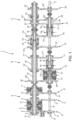
- Figure 1 discloses a transmission 1 for an off-road vehicle, such as an agricultural vehicle, e.g. a tractor (not illustrated), comprising an input shaft 2, operatively connected to an engine shaft carried by a torque source E, such as an internal combustion engine of the work vehicle, and an output shaft 3, which can be coupled to a drive axle of the off-road vehicle.
- a torque source E such as an internal combustion engine of the work vehicle
- an output shaft 3 which can be coupled to a drive axle of the off-road vehicle.
- the transmission 1 essentially comprises, operatively connected in series one to the other between input shaft 2 and output shaft 3, an input stage A, a gear ratio stage B, and a range gear ratio stage C.
- the input stage A may be realized in different manner in order to vary rotational direction of input shaft 2 towards gear ratio B, i.e. between a forward motion and a rearward motion.
- the input stage A comprises a first and a second gearings 4, 5 selectively connectable to a first support shaft 6.
- the first support shaft 6 provides input torque to the gear ratio stage B and is preferably divided into two portions, namely a first portion 6' and a second portion 6" that are coaxially and rotatably independent one with respect to the other.
- the first gearing 4 comprises a first wheel 4' rotatably carried by input shaft 2 ,a second wheel 4'' carried in a fixed manner by the first support shaft 6 and a third wheel 4′′′ operatively connecting the first and the second wheels 4', 4" while the second gearing comprises a first wheel 5' rotatably carried by input shaft 2 and a second wheel 5'' carried in a fixed manner by the first support shaft 6.
- the first wheels 4', 5' of gearings 4, 5 are selectively fixed to the input shaft 2 via respective first and second clutch means 7', 7'', namely a rearward clutch 7' and a first forward clutch 7".
- the input stage further comprises a third gearing 8 comprising a first wheel 8' rotatably carried by input shaft 2 and a second wheel 8'' carried in a fixed manner by the first support shaft 6 and third clutch means 7′′′, namely a second forward clutch 7'', configured to selectively fix to input shaft 2 the first wheel 8'.
- a third gearing 8 comprising a first wheel 8' rotatably carried by input shaft 2 and a second wheel 8'' carried in a fixed manner by the first support shaft 6 and third clutch means 7′′′, namely a second forward clutch 7'', configured to selectively fix to input shaft 2 the first wheel 8'.
- first, second and third gearings 4, 5, 8 have different gear ratios and all insist on the first portion 6' of the first support shaft 6.
- the third clutch means 7′′′ are carried by the input shaft 2 such as the second clutch means 7" and the first clutch means 7' that are therefore axially aligned along the axis of the input shaft 2.
- the gear ratio stage B comprises a plurality of gearings 11, 12, 13, 14 operatively interposed between the first support shaft 6 and the input shaft and having a different size one with respect to the other to define respective gear ratios between the input shaft 2 and the output shaft 3.
- the gear ratio stage B defines a first, a second, a third and a fourth gear ratios between the input and the output shafts 2, 3.
- the first support shaft 6 carries four gears 11', 12', 13', 14' and the input shaft 2 carries respective further four counter gears 11", 12'', 13", 14" meshing with the four gears 11', 12', 13', 14' to define the aforementioned gearings 11, 12, 13, 14.
- first gear 11' has the biggest diameter
- fourth gear has the smallest diameter
- second and third gears 12', 13' have respective diameters comprised between the ones of first and the fourth gears 11', 14'.
- the respective counter gears 11'', 12'', 13'', 14'' have a diameter corresponding the four gears 11', 12', 13', 14'.
- the gears 11', 12', 13', 14' are in part fixedly carried by the second portion 6'' and in part rotatably carried by this latter and selectively fixable thereon via selection means 19.
- the counter gears 11", 12", 13", 14'' are instead freely carried on the input shaft 2 via support shafts as disclosed in the following.
- the second support shaft 15 is rotatable free carried over the input shaft 2 and is operatively connected to the first portion of the input shaft 6 as described below.
- the third support shaft 18 is instead operatively connected to output shaft 3 as described further.
- the second support shaft 15 is connected to the first portion 6' of the first support shaft 6 via jump gearing 20 comprising a wheel 20' and a counter wheel 20''; the wheel 20' is rotatably free carried by the first portion 6' of the first support shaft 6 and the counter wheel 20'' is rigidly carried by the second support shaft 15.
- the gear ratio stage B comprises a fourth and a fifth clutch means 17', 17'', namely a clutch and an even clutches, configured to selectively fix the third wheel 13' of the third gearing 13 and the wheel20' of the jump gearing 20 to the first portion 6' of the first support shaft.
- the fourth and fifth clutch means 17', 17'' are carried by the first support shaft 6, in particular by the first portion 6' thereof, and are axially faced one with respect to the other along the longitudinal axis thereof.
- the jump gearing 20 is axially interposed between the third clutch means 7" ' and the fourth and fifth clutch means 17', 17''.
- the range gear stage C adds a plurality of additional gear ratio that are combined with the gear ratios defined by the gear ratio stage. In the disclosed embodiment, three range gear ratio are provided.
- the range gear ratio stage C then comprises a first and a range gearings 21, 23 each comprising a first wheel 21', 23', and a second wheel 21", 23".
- first range gearing 21 is the so-called medium range
- second range gearing 23 is the so-called low range
- the fast range is achieved as described below.
- the first and second range gearings 21, 23 both comprises a first wheel 21', 23' and a second wheel 21', 23''.
- the first wheel 21' of the first range gear 21 is rotatably free carried by the output shaft 3 in particular fixedly carried by an auxiliary shaft 24 rotatably free carried on the output shaft 3 while the first wheel 23' of the second range gearing 23 is rotatably free carried by the third auxiliary shaft 18.
- the second wheels 21" and 23" are instead fixedly carried by respectively the third auxiliary shaft 18 and by output shaft 3.
- the range gear stage further comprises a gearing 22 provided with a first wheel 22' that is rigidly carried by the auxiliary shaft 24 and a second wheel 22'' that is rotatably free carried over the third auxiliary shaft.
- auxiliary shaft 24 can be coupled to the output shaft via selection means 19 and similarly selection means 19 can connect together the second wheel 22" of the gearing 22 to the first wheel 23' of the first gearing 23.
- the range gear stage C further comprise selection means 19 configured to connect together the output shaft 3 directly to the second portion 6" of the first support shaft 6 thereby realizing a fast range ratio.
- the aforementioned selection means 19 can be realized in different manners such as synchronizer or dog clutches.
- the above-described clutches 7', 7", 7′′′, 17', 17" and selection means 19 can be selected by respective actuators (not shown) that are controlled by an electronic control unit (not shown).
- the electronic control unit controls said clutches or said control means by sending control electric signals directed to the respective clutches or selection means to be controlled.
- the electronic control unit can be either the ECU of the vehicle or driveline ECU of the vehicle.
- the electronic control unit is configured to control the above cited elements of the transmission 1 as per direct input command of the user of the vehicle or in automatic way following the shift control logic deployed into a specific software code, which can be memorized into the electronic unit.
- the vehicle may be provided by a dedicated control software code in the ECU of the transmission configured to recognize signals from sensors installed on the vehicle, e.g. the torque demand at the output shaft 3 and the speed of the engine input shaft 2, and automatically define the gearshift without any user intervention.
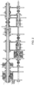
- the vehicle is driving, e.g. forward, in first-low gear ratio, i.e. in the configuration shown in figure 2 .
- the first forward clutch 7" couples the second gearing 5 wheels so that torque flows towards the first portion 6' of first support shaft 6
- fifth clutch means 17'' couples the gear 13' of the third gearing 13
- selection means 19 couples the gear 11' of the first gearing 11 so that torque passes through the common support shaft 16 to the second portion 6" of the first support shaft 6.
- the counter wheel 22'' of the second range gearing 22 is coupled to gearing 23 to output shaft, the torque flows via gearings 21, 22 and via second portion 6" of first support shaft 6 towards the output shaft 3.
- first forward clutch 7'' couples the second gearing 5 wheels so that torque flows towards the first portion 6' of first support shaft 6
- fourth clutch means 17' couples the gear 20' of the jump gearing 20 and torque passes through the second support shaft 15 to the counter wheel 12" of the second gearing that is coupled via selection means 19 to the second support shaft 15.
- the counter wheel 22'' of the second range gearing 22 is coupled to gearing 23 to output shaft, the torque flows via gearings 21, 22 and via second portion 6" of first support shaft 6 towards the output shaft 3.
- the transmission is provided with overall twenty four gear ratios, as listed (in forward motion) and only twelve gear ratios in rearward motion due to the presence of a single rearward clutch 7'.
- the invention also relates to a method for operating a transmission 1 as described above for shifting from a gear ratio of the gear ratio stage B to a requested gear ratio of the gear ratio stage B and comprising the following steps:
- the proposed transmission architecture allows to reduce the number of shafts and in particular of countershafts that are present in the known DCT arrangement thereby providing a high number of gear ratio and reducing weight, encumbrance and costs for producing the transmission.
- the inertia of the transmission architecture is further reduces since the torque transmission paths are shorter then the ones of known DCT arrangements.
- gears of gear ratio, range and idler gears may be varied according to vehicle necessity.
- the transmission may comprise different elements with respect to the described one, e.g. the number and/or typologies of clutches, gears and dog clutches may be varied.
- control and typology of selection means 19 may be implemented with any typology of control, e.g. a hydraulic, electric or pneumatic in alternative or in combinations.
Landscapes
- Engineering & Computer Science (AREA)
- General Engineering & Computer Science (AREA)
- Mechanical Engineering (AREA)
- Structure Of Transmissions (AREA)
Abstract
• an input shaft (2) configured to be coupled to a power source of the work vehicle,
• an output shaft (3) configured to be connected to a driving axle of the work vehicle,
• an input stage (A), a gear ratio stage (B) and a range gear ratio stage (C) operatively connected one to the other with respect to input shaft (2) and output shaft (3),
the gear ratio stage (B) and the range gear ratio stage (C) comprise gearing architecture to provide twenty four ratios between input shaft (2) and output shaft (3).
Description
- The present invention relates to a transmission architecture, in particular a transmission architecture for an off-road vehicle such as an agricultural vehicle and to a related method for controlling the gear shifting of such transmission.
- Transmissions for off-road vehicles such as agricultural vehicles offer different configuration, for instance:
- manual shifted transmissions, in which all gears of the transmissions are engaged directly by the driver through lever mechanisms which command clutches, synchronizers and dog clutches to select the gear;
- semi-powershift transmission, in which some gears are engaged, manually or automatically, thanks to servo actuated mechanisms in powershift mode, i.e. by swapping the torque by a couple of clutches, and in which other gears are actuated by lever mechanisms which commands clutches, synchronizers and dog clutches to select the gear or by a servo-actuated mechanism which is not in powershift mode, i.e. which uses a single clutch and, when such clutch is opened, torque cannot pass through the transmission; and
- full powershift transmission, in which all gears of the transmission are engaged through servo actuated mechanism in powershift mode.
- An important request that must be satisfied in modern mechanical transmission for agricultural vehicles is to have high efficiency across the full ground speed range, in order to improve the vehicle fuel consumption. In this respect a large use of wet clutches to build the semi-powershift or the full-powershift transmissions, generates more power losses inside the transmission when compared to the use of synchronizers and dog-clutches and, as consequence, a penalty of efficiency as consequence.
- For this reason, in the art, the dual-clutch transmission, DCT, architecture is considered the most valuable layout for powershift transmissions in order to satisfy all the previous demands:
- it provides a high number of speed ratios with a mechanism that allow for a comfortable powershift (by swapping one couple of clutches); and
- it performs high efficiency, because a powershift layout is provided by only few couples of wet clutches accompanied by many synchronizers and dog-clutches.
- Because of these advantages, recently DCT architecture has been applied in the field of the transmissions for agricultural vehicles.
- However new requirements request higher speeds of the agricultural vehicles in a wide torque range. This lead to high encumbrance and high weight transmission.
- Therefore, the need is felt to solve the aforementioned drawbacks in order to maintain a wide range of transmittable torque, at high speeds while reducing encumbrances of the transmission, its manufacturing time and therefore its costs.
- Aim of the present invention is to satisfy the above-mentioned needs in a cost-effective and optimized way.
- The aforementioned aim is reached by an architecture for a transmission and a related control method as claimed in the appended set of claims.
- For a better understanding of the present invention, a preferred embodiment is described in the following, by way of a non-limiting example, with reference to the attached drawings wherein:
-
Figure 1 is a schematic representation of a transmission architecture according to the present invention; -
Figures 2 and3 are schematic representations of the transmission architecture offigure 1 showing concerned power flows in two different exemplarily operative conditions; and -
Figure 4 is a table indicating the activation of elements of the transmission architecture according to the invention. -
Figure 1 discloses atransmission 1 for an off-road vehicle, such as an agricultural vehicle, e.g. a tractor (not illustrated), comprising aninput shaft 2, operatively connected to an engine shaft carried by a torque source E, such as an internal combustion engine of the work vehicle, and anoutput shaft 3, which can be coupled to a drive axle of the off-road vehicle. - The
transmission 1 essentially comprises, operatively connected in series one to the other betweeninput shaft 2 andoutput shaft 3, an input stage A, a gear ratio stage B, and a range gear ratio stage C. - The input stage A may be realized in different manner in order to vary rotational direction of
input shaft 2 towards gear ratio B, i.e. between a forward motion and a rearward motion. - In the exemplarily disclosed embodiment, the input stage A comprises a first and a
second gearings first support shaft 6. Thefirst support shaft 6 provides input torque to the gear ratio stage B and is preferably divided into two portions, namely a first portion 6' and asecond portion 6" that are coaxially and rotatably independent one with respect to the other. - The
first gearing 4 comprises a first wheel 4' rotatably carried byinput shaft 2 ,a second wheel 4'' carried in a fixed manner by thefirst support shaft 6 and athird wheel 4‴ operatively connecting the first and thesecond wheels 4', 4" while the second gearing comprises a first wheel 5' rotatably carried byinput shaft 2 and a second wheel 5'' carried in a fixed manner by thefirst support shaft 6. The first wheels 4', 5' ofgearings input shaft 2 via respective first and second clutch means 7', 7'', namely a rearward clutch 7' and a firstforward clutch 7". - The input stage further comprises a
third gearing 8 comprising a first wheel 8' rotatably carried byinput shaft 2 and a second wheel 8'' carried in a fixed manner by thefirst support shaft 6 and third clutch means 7‴, namely a second forward clutch 7'', configured to selectively fix to inputshaft 2 the first wheel 8'. - In detail, the first, second and
third gearings first support shaft 6. - In particular, the third clutch means 7‴ are carried by the
input shaft 2 such as the second clutch means 7" and the first clutch means 7' that are therefore axially aligned along the axis of theinput shaft 2. - The gear ratio stage B comprises a plurality of
gearings first support shaft 6 and the input shaft and having a different size one with respect to the other to define respective gear ratios between theinput shaft 2 and theoutput shaft 3. - In particular, the gear ratio stage B defines a first, a second, a third and a fourth gear ratios between the input and the
output shafts - Accordingly, the
first support shaft 6 carries fourgears input shaft 2 carries respective further fourcounter gears 11", 12'', 13", 14" meshing with the fourgears aforementioned gearings - In particular, the first gear 11' has the biggest diameter, the fourth gear has the smallest diameter and the second and
third gears 12', 13' have respective diameters comprised between the ones of first and thefourth gears 11', 14'. The respective counter gears 11'', 12'', 13'', 14'' have a diameter corresponding the fourgears - Advantageously, the
gears counter gears 11", 12", 13", 14'' are instead freely carried on theinput shaft 2 via support shafts as disclosed in the following. - In detail, according to the described advantageous embodiment:
- The gear 11' of the
first gearing 11 is rotatably free carried by thesecond portion 6" of thefirst support shaft 3 and selectively connectable to this latter via selection means 19; - The
gear 13' of thethird gearing 13 is rotatably free carried by at least one between the first andsecond portions 6', 6" of thefirst support shaft 3 and selectively connectable to thesecond portion 6" via selection means 19; - The
gears 12', 14' of the second andfourth gearings second portion 6" of thefirst support shaft 6. - On the other side:
- The counter gears 11'' and 13" of the first and
second gearings second support shaft 15 and commonly carried by acommon support shaft 16 that is rotatably carried over thesecond support shaft 15; - The
counter gear 12" of thesecond gearing 12 is rotatably free carried by thesecond support shaft 15 and selectively fixed to this latter via selection means 19; - The
counter gear 14'' of thefourth gearing 14 is fixedly carried by athird support shaft 18, thethird support shaft 18 is selectively fixed to thesecond support shaft 15 via selection means 19. - In detail, the
second support shaft 15 is rotatable free carried over theinput shaft 2 and is operatively connected to the first portion of theinput shaft 6 as described below. Thethird support shaft 18 is instead operatively connected tooutput shaft 3 as described further. - The
second support shaft 15 is connected to the first portion 6' of thefirst support shaft 6 viajump gearing 20 comprising a wheel 20' and a counter wheel 20''; the wheel 20' is rotatably free carried by the first portion 6' of thefirst support shaft 6 and the counter wheel 20'' is rigidly carried by thesecond support shaft 15. - Advantageously, the gear ratio stage B comprises a fourth and a fifth clutch means 17', 17'', namely a clutch and an even clutches, configured to selectively fix the
third wheel 13' of thethird gearing 13 and the wheel20' of the jump gearing 20 to the first portion 6' of the first support shaft. - Preferably the fourth and fifth clutch means 17', 17'' are carried by the
first support shaft 6, in particular by the first portion 6' thereof, and are axially faced one with respect to the other along the longitudinal axis thereof. - In further detail, the
jump gearing 20 is axially interposed between the third clutch means 7" ' and the fourth and fifth clutch means 17', 17''. - The range gear stage C adds a plurality of additional gear ratio that are combined with the gear ratios defined by the gear ratio stage. In the disclosed embodiment, three range gear ratio are provided.
- In the disclosed embodiment, the range gear ratio stage C then comprises a first and a
range gearings second wheel 21", 23". In particular,first range gearing 21 is the so-called medium range, thesecond range gearing 23 is the so-called low range and the fast range is achieved as described below. - The first and
second range gearings first range gear 21 is rotatably free carried by theoutput shaft 3 in particular fixedly carried by anauxiliary shaft 24 rotatably free carried on theoutput shaft 3 while the first wheel 23' of thesecond range gearing 23 is rotatably free carried by the thirdauxiliary shaft 18. Thesecond wheels 21" and 23" are instead fixedly carried by respectively the thirdauxiliary shaft 18 and byoutput shaft 3. - The range gear stage further comprises a
gearing 22 provided with a first wheel 22' that is rigidly carried by theauxiliary shaft 24 and a second wheel 22'' that is rotatably free carried over the third auxiliary shaft. - In detail, the
auxiliary shaft 24 can be coupled to the output shaft via selection means 19 and similarly selection means 19 can connect together thesecond wheel 22" of thegearing 22 to the first wheel 23' of thefirst gearing 23. - The range gear stage C further comprise selection means 19 configured to connect together the
output shaft 3 directly to thesecond portion 6" of thefirst support shaft 6 thereby realizing a fast range ratio. - The aforementioned selection means 19 can be realized in different manners such as synchronizer or dog clutches.
- The above-described
clutches 7', 7", 7‴, 17', 17" and selection means 19 can be selected by respective actuators (not shown) that are controlled by an electronic control unit (not shown). The electronic control unit controls said clutches or said control means by sending control electric signals directed to the respective clutches or selection means to be controlled. - The electronic control unit can be either the ECU of the vehicle or driveline ECU of the vehicle. The electronic control unit is configured to control the above cited elements of the
transmission 1 as per direct input command of the user of the vehicle or in automatic way following the shift control logic deployed into a specific software code, which can be memorized into the electronic unit. - The vehicle may be provided by a dedicated control software code in the ECU of the transmission configured to recognize signals from sensors installed on the vehicle, e.g. the torque demand at the
output shaft 3 and the speed of theengine input shaft 2, and automatically define the gearshift without any user intervention. - The operation of the
transmission 1 according to the invention are described in the following making reference tofigures 2 ,3 and to table offigure 4 . - The vehicle is driving, e.g. forward, in first-low gear ratio, i.e. in the configuration shown in
figure 2 . - In such configuration, the first
forward clutch 7" couples thesecond gearing 5 wheels so that torque flows towards the first portion 6' offirst support shaft 6, fifth clutch means 17'' couples thegear 13' of thethird gearing 13 and selection means 19 couples the gear 11' of thefirst gearing 11 so that torque passes through thecommon support shaft 16 to thesecond portion 6" of thefirst support shaft 6. Then since the counter wheel 22'' of the second range gearing 22 is coupled to gearing 23 to output shaft, the torque flows viagearings second portion 6" offirst support shaft 6 towards theoutput shaft 3. - Supposing to pass to in second-low gear ratio, i.e. in the configuration shown in
figure 3 , it is sufficient to swap fourth and fifth clutches 17', 17''. - In such configuration, the first forward clutch 7'' couples the
second gearing 5 wheels so that torque flows towards the first portion 6' offirst support shaft 6, fourth clutch means 17' couples the gear 20' of thejump gearing 20 and torque passes through thesecond support shaft 15 to thecounter wheel 12" of the second gearing that is coupled via selection means 19 to thesecond support shaft 15. Then since the counter wheel 22'' of the second range gearing 22 is coupled to gearing 23 to output shaft, the torque flows viagearings second portion 6" offirst support shaft 6 towards theoutput shaft 3. - The remaining gear ratios and derivable pre-selection of gears and swap of clutches are disclosed in the summarizing table of
figure 4 and are not further reported for sake of brevity. - Due to the proposed eight gears ratio and the three range gear ratio, the transmission is provided with overall twenty four gear ratios, as listed (in forward motion) and only twelve gear ratios in rearward motion due to the presence of a single rearward clutch 7'.
- The invention also relates to a method for operating a
transmission 1 as described above for shifting from a gear ratio of the gear ratio stage B to a requested gear ratio of the gear ratio stage B and comprising the following steps: - i) receiving an input for shifting from a gear ratio of gear ratio stage B to a requested gear ratio of the gear ratio stage B;
- ii) if the requested gear ratio foresees the use of the same initial gear of the gear ratio stage B, then proceed to step v) otherwise proceed with steps iii) and iv);
- iii) engage by selection means 19 a further gear involved in the requested gear ratio to the second range gear shaft;
- iv)
swap clutches 7', 7", 17', 17'' involved in the torque transmission to pass from the initial gear to the further gear; - v) swap clutches 7', 7'', 17', 17'' involved in the torque transmission to pass to the requested gear ratio.
- In view of the foregoing, the advantages of a
transmission architecture 1 according to the invention and the related method are apparent. - The proposed transmission architecture allows to reduce the number of shafts and in particular of countershafts that are present in the known DCT arrangement thereby providing a high number of gear ratio and reducing weight, encumbrance and costs for producing the transmission.
- Indeed, with only a further forward clutch and with the arrangement of the even/odd clutches in an axial alignment, it is possible to avoid the use of countershaft and manages the torque into twenty-four gear ratios in a very compact manner.
- Moreover, since shafts and gears are reduced, the overall number of components is reduced and then the manufacturing costs are contained.
- Clearly, the inertia of the transmission architecture is further reduces since the torque transmission paths are shorter then the ones of known DCT arrangements.
- It is clear that modifications can be applied to the described
transmission 1 which do not extend beyond the scope of protection defined by the claims. - For example, the number and typology of gears of gear ratio, range and idler gears may be varied according to vehicle necessity.
- Further, the transmission may comprise different elements with respect to the described one, e.g. the number and/or typologies of clutches, gears and dog clutches may be varied.
- Moreover, the control and typology of selection means 19 may be implemented with any typology of control, e.g. a hydraulic, electric or pneumatic in alternative or in combinations.
Claims (14)
- An architecture for a dual clutch transmission (1) for a work vehicle, said dual clutch transmission (1) comprising:• an input shaft (2) configured to be coupled to a power source (E) of said work vehicle,• an output shaft (3) configured to be connected to a driving axle of said work vehicle,• an input stage (A), a gear ratio stage (B) and a range gear ratio stage (C) operatively connected one to the other with respect to said input shaft (2) and said output shaft (3),wherein said input stage (A) comprises a first transmission shaft (6) comprising a first portion (6'), a first and a second gearings (4, 5) operatively interposed between the input shaft (2) and said first portion (6'), a first and a second clutches (7', 7'') configured to select one between said first and second gearings (4, 5) between said input shaft (2) and said first portion (6'),said input stage (A) further comprising a third gearing (8) operatively interposed between the input shaft (2) and said first portion (6') and third clutch means (7‴) configured to select such third gearing (8),said gear ratio stage (B) comprise a second portion (6") of said first support shaft (6) independent to said first portion (6') and a plurality of gearings (11, 12, 13, 14) operatively interposed between said second portion (6") and the input shaft (2) and operatively connected to said output shaft (3) to define different gear ratios between said input shaft (2) and said output shaft (3),said gearings (11, 12, 13, 14) comprising a plurality of gears (11', 12', 13', 14') carried by said second portion (6'') and respective counter gears (11", 12'', 13'', 14'') configured to mesh with said gears (11', 12', 13', 14') to define different ratios, said gears (11', 12', 13', 14') being in part fixedly carried by said second portion (6") and in part rotatably carried by said second portion (6") and selectively fixable to this latter via selection means (19), said counter gears (11'', 12'', 13", 14'') being rotatably carried by a second or a third support shaft (15, 18),said third support shaft (18) being rotatably carried by said input shaft (2) and operatively connected to said output shaft (3), said second support shaft (15) being rotatably carried by said input shaft (2) and being operatively connected via a jump gearing (20) to said first portion (6') of said first support shaft (6), said jump gearing (20) comprising a first wheel (20') rotatably free carried by said first portion (6') and selectively connectable to this latter via fourth clutch means (17'),one gear (13') among said gears (11", 12", 13", 14") being selectively connectable to said first portion (6') via fifth clutch means (17").
- Architecture according to claim 1, wherein said first, second and third clutch means (7', 7'', 7‴) are coaxial to said input shaft (2).
- Architecture according to claim 1 or 2, wherein said fourth and fifth clutch means (17', 17") are coaxial to said first support shaft (6).
- Architecture according to any of claims 1 to 3, wherein said jump gearing (20) is axially interposed between said third clutch means (7‴) and fourth and fifth clutch means (17', 17").
- Architecture according to any of the preceding claims, wherein said first, second and third gearings (4, 5, 8) of said input stage (A) each comprises at least a first wheel (4', 5', 8') rotatably carried by said input shaft (2) and selectively fixed to this latter via a respective clutch means (7', 7'', 7‴) and a second wheel (4", 5", 8'') meshing with the respective (4', 5', 8') to define different gear ratios, said second wheels (4", 5", 8") are fixedly carried by said first portion (6').
- Architecture according to any of the preceding claims, wherein- the gear (11') of the first gearing (11) is rotatably free carried by the second portion (6") of the first support shaft (3) and selectively connectable to this latter via selection means (19);• The gear (13') of the third gearing (13) is rotatably free carried by at least one between the first and second portions (6', 6") of the first support shaft (3) and selectively connectable to the second portion (6'') via selection means (19);• The gears (12', 14') of the second and fourth gearings (12, 14) are fixedly carried by the second portion (6'') of the first support shaft (6);and wherein:• The counter gears (11") and (13'') of the first and second gearings (11, 13) are rotatably free carried over said second support shaft (15) and commonly carried by a common support shaft (16) that is rotatably carried over the second support shaft (15);• The counter gear (12'') of the second gearing (12) is rotatably free carried by the second support shaft (15) and selectively fixed to this latter via selection means (19) ;• The counter gear (14'') of the fourth gearing (14) is fixedly carried by said third support shaft (18), the third support shaft (18) is selectively fixed to the second support shaft (15) via selection means (19).
- Architecture according to claim 6, wherein said jump gearing (20) comprises a second wheel (20") fixedly carried by said second support shaft (15).
- Architecture according to any of claims 4 to 7, wherein said range gear stage (C) comprises a first and a second gearings (21, 23), said first gearing (23) comprising a first wheel (23') rotatably free carried by said third support shaft (18) and a second wheel (23") fixedly carried by said output shaft (3), wherein said second gearing (21) comprises a first gear (21') fixedly carried by an auxiliary shaft (24) that is rotatably free carried over said output shaft (3) and a second gear (21'') fixedly carried by said third support shaft (18), wherein said auxiliary shaft (24) being selectively fixed to the output shaft (3) via selection means (19).
- Architecture according to claim 8, wherein range stage (C) comprises a gearing (22) comprising a first wheel (22') rotatably carried by said third support shaft (18) and selectively connected to said first wheel (23') of said first gearing (23) via selection means (19) and a second wheel (22") fixedly carried by said auxiliary shaft (24).
- Architecture according to any of claims 4 to 7, further comprising selection means (17) for selectively coupling said sleeve (23) to said output shaft (3).
- Architecture according to any of claims 8 to 10, further comprising selection means (19) for selectively coupling said second portion (6") of said first support shaft (6) to said output shaft (3).
- Architecture according to any of the preceding claims, wherein said selection means (19) comprises a synchronizer or a dog clutch.
- Architecture according to any of the preceding claims further comprising a control unit configured to control actuators configured to regulate the operation of said clutch means (7', 7", 7‴, 17', 17") and said selection means (19).
- Method for operating a transmission architecture (1) as claimed in any of the aforementioned claims for shifting from a gear ratio of the gear ratio stage (B) to a requested gear ratio of the gear ratio stage (B) and comprising the following steps:• i) receiving an input for shifting from a gear ratio of gear ratio stage (B) to a requested gear ratio of the gear ratio stage (B);• ii) if the requested gear ratio foresees the use of the same initial gear of the gear ratio stage (B), then proceed to step v) otherwise proceed with steps iii) and iv);• iii) engage by selection means (19) a further gear involved in the requested gear ratio to the second range gear shaft;• iv) swap clutch means (7', 7", 7‴, 17', 17'') involved in the torque transmission to pass from the initial gear to the further gear;• v) swap clutch means (7', 7", 7‴, 17', 17'') involved in the torque transmission to pass to the requested gear ratio.
Applications Claiming Priority (1)
| Application Number | Priority Date | Filing Date | Title |
|---|---|---|---|
| IT102023000015474A IT202300015474A1 (en) | 2023-07-24 | 2023-07-24 | IMPROVED TRANSMISSION ARCHITECTURE FOR AGRICULTURAL VEHICLES |
Publications (1)
| Publication Number | Publication Date |
|---|---|
| EP4497970A1 true EP4497970A1 (en) | 2025-01-29 |
Family
ID=88146808
Family Applications (1)
| Application Number | Title | Priority Date | Filing Date |
|---|---|---|---|
| EP24189778.4A Pending EP4497970A1 (en) | 2023-07-24 | 2024-07-19 | Improved transmission architecture for agricultural vehicles |
Country Status (2)
| Country | Link |
|---|---|
| EP (1) | EP4497970A1 (en) |
| IT (1) | IT202300015474A1 (en) |
Citations (4)
| Publication number | Priority date | Publication date | Assignee | Title |
|---|---|---|---|---|
| FR2109790A5 (en) * | 1970-10-07 | 1972-05-26 | Kloeckner Humboldt Deutz Ag | |
| US6044720A (en) * | 1998-04-13 | 2000-04-04 | Kanzaki Kokyukoki Mfg. Co., Ltd. | Drive transmission assembly for working vehicles |
| EP1400724A2 (en) * | 2002-09-20 | 2004-03-24 | Isuzu Motors Limited | Transmission |
| US20060243513A1 (en) * | 2005-04-27 | 2006-11-02 | Kubota Corporation | Transmission for a tractor |
-
2023
- 2023-07-24 IT IT102023000015474A patent/IT202300015474A1/en unknown
-
2024
- 2024-07-19 EP EP24189778.4A patent/EP4497970A1/en active Pending
Patent Citations (4)
| Publication number | Priority date | Publication date | Assignee | Title |
|---|---|---|---|---|
| FR2109790A5 (en) * | 1970-10-07 | 1972-05-26 | Kloeckner Humboldt Deutz Ag | |
| US6044720A (en) * | 1998-04-13 | 2000-04-04 | Kanzaki Kokyukoki Mfg. Co., Ltd. | Drive transmission assembly for working vehicles |
| EP1400724A2 (en) * | 2002-09-20 | 2004-03-24 | Isuzu Motors Limited | Transmission |
| US20060243513A1 (en) * | 2005-04-27 | 2006-11-02 | Kubota Corporation | Transmission for a tractor |
Also Published As
| Publication number | Publication date |
|---|---|
| IT202300015474A1 (en) | 2025-01-24 |
Similar Documents
| Publication | Publication Date | Title |
|---|---|---|
| US7360466B2 (en) | Double clutch transmission | |
| US7958798B2 (en) | Speed change system for working vehicle | |
| EP2256369B1 (en) | Dual-clutch transmission for vehicle | |
| US7621195B2 (en) | Vehicle transmission | |
| EP2510259B1 (en) | Powershift transmission for a motor vehicle | |
| EP2126411B2 (en) | Multiple-ratio dual clutch vehicle transmission | |
| EP3911873B1 (en) | Dual clutch transmission electric hybrid architecture for agricultural vehicles | |
| US6826974B2 (en) | Automatic transmission | |
| EP0046373A1 (en) | Rotary transmission | |
| US6647817B2 (en) | Automatic transmission | |
| US20090266190A1 (en) | Multi-group transmission of a motor vehicle | |
| EP4585828A1 (en) | Improved transmission architecture for agricultural vehicles | |
| EP4497976A1 (en) | Improved transmission architecture for agricultural vehicles | |
| EP4497974A1 (en) | Improved transmission architecture for agricultural vehicles | |
| EP4497975A1 (en) | Improved transmission architecture for agricultural vehicles | |
| EP4497969A2 (en) | Improved transmission architecture for agricultural vehicles | |
| EP4411174A1 (en) | Double clutch architecture transmission for agricultural vehicles | |
| EP4411172A1 (en) | Double clutch architecture transmission for agricultural vehicles | |
| JPS61274147A (en) | Gear type speed changer | |
| EP4411173A1 (en) | Double clutch architecture transmission for agricultural vehicles | |
| EP4411171A1 (en) | Double clutch architecture transmission for agricultural vehicles | |
| US20250215963A1 (en) | Dual clutch transmission architecture for agricultural vehicles | |
| CN111779814A (en) | A hydromechanical power-shift transmission suitable for high-horsepower tractors | |
| IT202300015474A1 (en) | IMPROVED TRANSMISSION ARCHITECTURE FOR AGRICULTURAL VEHICLES | |
| IT202200024720A1 (en) | IMPROVED TRANSMISSION ARCHITECTURE FOR AGRICULTURAL VEHICLES |
Legal Events
| Date | Code | Title | Description |
|---|---|---|---|
| PUAI | Public reference made under article 153(3) epc to a published international application that has entered the european phase |
Free format text: ORIGINAL CODE: 0009012 |
|
| STAA | Information on the status of an ep patent application or granted ep patent |
Free format text: STATUS: THE APPLICATION HAS BEEN PUBLISHED |
|
| AK | Designated contracting states |
Kind code of ref document: A1 Designated state(s): AL AT BE BG CH CY CZ DE DK EE ES FI FR GB GR HR HU IE IS IT LI LT LU LV MC ME MK MT NL NO PL PT RO RS SE SI SK SM TR |
|
| STAA | Information on the status of an ep patent application or granted ep patent |
Free format text: STATUS: REQUEST FOR EXAMINATION WAS MADE |
|
| 17P | Request for examination filed |
Effective date: 20250729 |
|
| GRAP | Despatch of communication of intention to grant a patent |
Free format text: ORIGINAL CODE: EPIDOSNIGR1 |
|
| STAA | Information on the status of an ep patent application or granted ep patent |
Free format text: STATUS: GRANT OF PATENT IS INTENDED |
|
| INTG | Intention to grant announced |
Effective date: 20260410 |
|
| GRAS | Grant fee paid |
Free format text: ORIGINAL CODE: EPIDOSNIGR3 |
|
| GRAA | (expected) grant |
Free format text: ORIGINAL CODE: 0009210 |
|
| STAA | Information on the status of an ep patent application or granted ep patent |
Free format text: STATUS: THE PATENT HAS BEEN GRANTED |