EP4497967A1 - Belt and actuator belt system - Google Patents
Belt and actuator belt system Download PDFInfo
- Publication number
- EP4497967A1 EP4497967A1 EP23188484.2A EP23188484A EP4497967A1 EP 4497967 A1 EP4497967 A1 EP 4497967A1 EP 23188484 A EP23188484 A EP 23188484A EP 4497967 A1 EP4497967 A1 EP 4497967A1
- Authority
- EP
- European Patent Office
- Prior art keywords
- belt
- bump
- elements
- link
- inlay
- Prior art date
- Legal status (The legal status is an assumption and is not a legal conclusion. Google has not performed a legal analysis and makes no representation as to the accuracy of the status listed.)
- Pending
Links
Images


Classifications
-
- F—MECHANICAL ENGINEERING; LIGHTING; HEATING; WEAPONS; BLASTING
- F16—ENGINEERING ELEMENTS AND UNITS; GENERAL MEASURES FOR PRODUCING AND MAINTAINING EFFECTIVE FUNCTIONING OF MACHINES OR INSTALLATIONS; THERMAL INSULATION IN GENERAL
- F16G—BELTS, CABLES, OR ROPES, PREDOMINANTLY USED FOR DRIVING PURPOSES; CHAINS; FITTINGS PREDOMINANTLY USED THEREFOR
- F16G1/00—Driving-belts
- F16G1/06—Driving-belts made of rubber
- F16G1/08—Driving-belts made of rubber with reinforcement bonded by the rubber
- F16G1/10—Driving-belts made of rubber with reinforcement bonded by the rubber with textile reinforcement
-
- F—MECHANICAL ENGINEERING; LIGHTING; HEATING; WEAPONS; BLASTING
- F16—ENGINEERING ELEMENTS AND UNITS; GENERAL MEASURES FOR PRODUCING AND MAINTAINING EFFECTIVE FUNCTIONING OF MACHINES OR INSTALLATIONS; THERMAL INSULATION IN GENERAL
- F16G—BELTS, CABLES, OR ROPES, PREDOMINANTLY USED FOR DRIVING PURPOSES; CHAINS; FITTINGS PREDOMINANTLY USED THEREFOR
- F16G1/00—Driving-belts
- F16G1/28—Driving-belts with a contact surface of special shape, e.g. toothed
Definitions
- the present invention relates to belt and an actuator belt system.
- chains are used to be driven by actuator system such as gears that drive the chain and also may further stack the link elements of the chain.
- actuator system such as gears that drive the chain and also may further stack the link elements of the chain.
- Such a chain in combination with a corresponding actuator means may be used to lift or to push a load or drive a rotating element.
- this connecting actuator element or belt actuator may be used by a robotic system to change a position of a tooling member that is connected to the robotic system via said connectings elements.
- a belt comprising:
- the belt has a flat-shaped inlay element of a flexible material that is embedded inside of the belt that allows the belt to be flexible.
- the belt system becomes very stiff and can be used for example in an actuator system as connecting means or force transmitting means to drive or to move for example a tool that is connected to the actuator belt system.
- the manufacturing of the belt is easy and cost-efficient.
- a further advantage of the belt is that it can be easily adapted to different fields of applications.
- the link element and the connecting bridge member is made of one material that is non-compressable and flexible. In this way, the belt can be easily and at low costs manufactured and be easily used for different technical applications.
- the one material of the belt is at least one of a PU material or a rubber material. In this way, the belt can be easily and at low costs manufactured.
- the belt comprising of a solid material.
- the advantage is achieved that the belt does hardly deform under pressure or is able to withstand a certain pressure.
- the inlay element is made of at least one of the following flexible material: steel, fiber glas, carbon fiber, nylon.
- the belt can be easily adapted to changing technical requirements that are required when the belt is used in different technical fields of applications.
- the inlay element of the belt comprises a plurality of single inlay elements that are distanced between each other. In this way, the belt can be made flexible.
- the tooth-shaped bump element of a link element has a surface comprising a first rising edge element that is connected to a first base element and a second falling edge element that is connected to a second base element.
- the tooth-shaped bump elements are arranged in a synchronized manner. In this way, the belt can be easily manufactured.
- a belt actuactor system comprising a first belt element and a second belt element, wherein the first belt element is positioned on the second belt element in a zip-fastening manner in which the bump element of the first belt element is arranged or located inside a corresponding cavity of the second belt element.
- the belt system or belt actuator system comprises at least a second belt element, for example, a second belt element as described above or below.
- the belt actuator system may comprise a first belt element and a second belt element, wherein the first belt element is positioned on the second belt element in a zip-fastening manner in which the bump element of the first belt element is arranged or located inside a corresponding cavity of the second belt element.
- Fig. 1 illustrates a schematic example of a belt 1 according to an embodiment of the present invention.
- the belt 1 comprises a plurality of elements 10, 20 connected to each other in an end-to-end-manner having a first link element 10 and at least a second link element 20 connected to each other by a connecting bridge member 8.
- Each of the link elements 10, 20 having a body 7 from which a first bump element 2, 3 and opposite to the first bump element 2, 3 a second bump element 2', 3' elevates.
- the tooth-shaped first bump element 2, 3 and forming the top element or top side or front side of the belt 1 is opposite to the tooth-shaped second bump element 2', 3' which forms the bottom element or backside of the belt 1.
- the first bump element 2, 3 forms an end-to-end connection line to the second bump element 2', 3'.
- the first bump element 2, 3 and the second bump element 2', 3' arranged in Fig. 1 in a synchronized or regular manner.
- an unsychronized arrangement of the first bump element 2, 3 and the second bump element 2', 3' or a combinination thereof may also be possible.
- Both bump elements 2, 2', 3, 3' are configured in a tooth-like shape.
- the first bump element 2, 2' of the first link element 10 and the first bump element 3, 3' of the second link element 20 are configured to form a cavity or a notch 4, 5 between the first bump element 2, 2' and the second bump element 3, 3'.
- the base or bottom of the notch 4, 5 is formed by the bridge member 8.
- t the tooth-shaped bump element 2, 2', 3, 3' of the link element 10, 20 has a surface 13 comprising a first rising edge element 14 that is connected to a first base element 17 and a second falling edge element 15 that is connected to a second base element 18.
- the form or shape of the bump elements 2, 3 of the topside of the belt 1 may be the same or may differ.
- the form or shape of the bump elements 2, 3 of the topside compared to the form of the bump elements 2', 3' arranged on the backside of the belt 1 of the belt 1 may be the same or may differ, depending on the field of application of the belt 1.
- Te form or shape of the bump elements 2, 2', 3, 3' may be of any preferred shape, e.g. rectangular, triangular, rounded etc.
- the bump elements 2, 2', 3, 3' may have any preferred size and or thickness depending on the used-case of application. However, the number of teeth or number of bump elements 2, 2', 3, 3' or link elements 10, 20 on the topside and on the backside of the belt 1 is the same.
- a height (see y-axis in Fig. 1 ) of the first bump element 2, 3 is larger that a height of the second bum element 2', 3'.
- the first bump element 2, 3 f the second bump element 2', 3' may also be possible that the first bump element 2, 3 f the second bump element 2', 3' differ in their heights related to a horizontal x-axis shown in Fig. 1 .
- Each of the link elements 10, 20 and the connecting bridge members 8 between each link element 10, 20 of the belt 1 is made of one material that is non-compressable and flexible.
- the one material is at least one of a PU material or a rubber material to enable the entire belt 1 to be movable in a flexible manner.
- the belt 1 of the present invention is made of PU material and steel cords 12.
- the base of the belt 1 is optionally a T10 belt form (tooth) and on the backside of this T10 part a special for this purpose designed tooth form is added.
- the belt 1 may further be made of a solid material.
- a flat-shaped inlay element 12 of a flexible material is embedded or arranged in a longitudinal direction inside the belt 1 in the first link element 10 and the connecting bridge member 8.
- the inlay element 12 is as an example embodiment a continuously arranged element that deviates in a horizontal direction through all bump elements 2, 2', 3, 3' and bridge members 8.
- the inlay element 12 is made of at least one of the following flexible material: steel, fiber glas, carbon fiber, nylon.
- the preferred material of the inlay element or chord 12 should be of that kind that the inlay element 12 does not stretch inside the belt 1.
- Fig. 2-1 illustrates a schematic example of a part of the belt 1 according to an embodiment of the present invention indicating a sectionional view A-A that is detailed in Fig. 2-2 .
- the Fig. 2-1 shows a link element with a first bump element on the topside and a second bump element opposite the first bump element on the backside.
- Fig. 2-2 the horizontal arrangement of the plurality of inlay elements 12, 12' in shown.
- the Fig. 2-2 further shows, contrary to the embodiment of the belt 1 of Fig. 1 in an optional embodiment a plurality of single inlay-elements 12, 12' that are arranged in a certain distance between each other between the first bump element and the second bump element.
- the inlay elements 12, 12' may be flat shaped, but the shape is not restricted to such an embodiment.
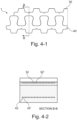
- Fig. 4-1 illustrates a schematic example of a belt 1 according to an embodiment of the present invention.
- the belt 1 consists of a first belt element 30 and a second belt element 40 that are arranged in a zip-fastening manner and are both rolled into each other.
- the bump element 2, 2' (see Fig. 1 ) of the first belt element 30 is arranged or located inside a corresponding cavity or notch 4, 5 (see Fig. 1 ) of the second belt element 40.
- the entire belt 1 becomes very stiff.
- the rolling the the separate belt elements 30, 40 may be done by an actuator system.
- Fig. 4-2 illustrates a sectional view of a belt 1 with the two belt elements 30, 40 according to Fig. 4-1 .
- Fig. 4-1 the horizontal arrangement of the inlay elements or chords 32, 32' (upper line of dots) and 42, 42' (base line of dots) of the two belt elements 30, 40 of the belt 1 as shown in Fig. 4-1 can be seen.
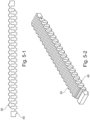
- Fig. 5-1 illustrates a schematic example of a belt 1 having a first belt element 30 and a second belt element 40 interconnected to each other in a zip-fastining manner, as described in Fig. 5-2 .
- the belt 1 is very flexible as a single belt, but when the two belt elements 30, 40 are rolled into each other they become very stiff.
- Fig. 5-2 illustrates a schematic example of the belt 1 of Fig. 5-1 in a 3D view according to an embodiment of the present invention.
Landscapes
- Engineering & Computer Science (AREA)
- General Engineering & Computer Science (AREA)
- Mechanical Engineering (AREA)
- Textile Engineering (AREA)
- Devices For Conveying Motion By Means Of Endless Flexible Members (AREA)
Abstract
The present invention relates a belt (1, 30, 40) comprising:
- a plurality of elements (10, 20) connected to each other having a first link element (10) and at least a second link element (20) connected to each other by a connecting bridge member (8),
- wherein each of the link elements (10, 20) having a body (7) from which a first bump element (2, 3) and opposite to the first bump element (2, 3) a second bump element (2', 3') elevates,
- wherein both bump elements (2, 2', 3, 3') are configured in a tooth-like shape, and
- at least a flat-shaped inlay element (12) of a flexible material that is embedded inside the belt (1) in the first link element (10) and the connecting bridge member (8).
- a plurality of elements (10, 20) connected to each other having a first link element (10) and at least a second link element (20) connected to each other by a connecting bridge member (8),
- wherein each of the link elements (10, 20) having a body (7) from which a first bump element (2, 3) and opposite to the first bump element (2, 3) a second bump element (2', 3') elevates,
- wherein both bump elements (2, 2', 3, 3') are configured in a tooth-like shape, and
- at least a flat-shaped inlay element (12) of a flexible material that is embedded inside the belt (1) in the first link element (10) and the connecting bridge member (8).
Description
- The present invention relates to belt and an actuator belt system.
- In prior art, chains are used to be driven by actuator system such as gears that drive the chain and also may further stack the link elements of the chain. Such a chain in combination with a corresponding actuator means may be used to lift or to push a load or drive a rotating element.
- In a further application, a chain or to be more general, this connecting actuator element or belt actuator may be used by a robotic system to change a position of a tooling member that is connected to the robotic system via said connectings elements.
- However, these chains known in prior art are made of metal which makes the chain difficult to handle due to its weight and its often rigid structure. Also the production of such a chain is difficult and expensive due to a complex production process of connecting the plurality of link elements of such a chain in an end-to-end manner. Further, the application of such a chain is usually restricted to a certain technical field.
- There is a need to address these issues.
- Therefore, it would be advantageous to provide an improved concept for a belt and a belt actuator system that can be manufactured in an easy and cost-efficient manner and is further easy to adaptable for different applications.
- The object of the present invention is solved by the subject matter of the independent claims, wherein further embodiments are incorporated in the dependent claims.
- In a first aspect of the present invention, there is provided a belt comprising:
- a plurality of elements connected to each other having a first link element and at least a second link element connected to each other by a connecting bridge member,
- wherein each of the link elements having a body from which a first bump element and opposite to the first bump element a second bump element elevates, and
- at least a flat-shaped inlay element of a flexible material that is embedded inside the belt in the first link element and the connecting bridge member.
- One important aspect of the belt is that the belt has a flat-shaped inlay element of a flexible material that is embedded inside of the belt that allows the belt to be flexible. However, when two belts are rolled into each other in a zipped-like manner, the belt system becomes very stiff and can be used for example in an actuator system as connecting means or force transmitting means to drive or to move for example a tool that is connected to the actuator belt system.
- As the belt is made of one single material, the manufacturing of the belt is easy and cost-efficient.
- A further advantage of the belt is that it can be easily adapted to different fields of applications.
- According to an example, the link element and the connecting bridge member is made of one material that is non-compressable and flexible. In this way, the belt can be easily and at low costs manufactured and be easily used for different technical applications.
- According to an example, the one material of the belt is at least one of a PU material or a rubber material. In this way, the belt can be easily and at low costs manufactured.
- According to an example, the belt comprising of a solid material. In this way, the advantage is achieved that the belt does hardly deform under pressure or is able to withstand a certain pressure.
- According to an example, the inlay element is made of at least one of the following flexible material: steel, fiber glas, carbon fiber, nylon. In this way, the belt can be easily adapted to changing technical requirements that are required when the belt is used in different technical fields of applications.
- According to an example, the inlay element of the belt comprises a plurality of single inlay elements that are distanced between each other. In this way, the belt can be made flexible.
- According to an example, each of the plurality of inlay elements comprises of a single material or different materials. In this way, the properties of the belt can be easily adapted to the needs of different applications.
- According to an example, the tooth-shaped bump element of a link element has a surface comprising a first rising edge element that is connected to a first base element and a second falling edge element that is connected to a second base element. In this way, a simple and cost-efficient geometry of the belt is provided that can be easily adapted.
- Accordig to an example, the tooth-shaped bump elements are arranged in a synchronized manner. In this way, the belt can be easily manufactured.
- In a second aspect of the present invention, a belt actuactor system is provided, wherein the belt actuator system comprises a first belt element and a second belt element, wherein the first belt element is positioned on the second belt element in a zip-fastening manner in which the bump element of the first belt element is arranged or located inside a corresponding cavity of the second belt element.
- The belt system or belt actuator system comprises at least a second belt element, for example, a second belt element as described above or below.
- The belt actuator system may comprise a first belt element and a second belt element, wherein the first belt element is positioned on the second belt element in a zip-fastening manner in which the bump element of the first belt element is arranged or located inside a corresponding cavity of the second belt element.
- Exemplary embodiments will be described in the following with reference to the following drawings:
-
Fig. 1 illustrates a schematic example of a belt according to an embodiment of the present invention; -
Fig. 2-1 illustrates a schematic example of a part of the belt according to an embodiment of the present invention; -
Fig. 2-2 illustrates a sectional view of a belt according to an embodiment of the present invention; -
Fig. 3 illustrates a schematic example of a belt in 3D view according to an embodiment of the present invention; -
Fig. 4-1 illustrates a schematic example of a belt according to an embodiment of the present invention; -
Fig. 4-2 illustrates a sectional view of a belt according to an embodiment of the present invention; -
Fig. 5-1 illustrates a schematic example of a belt in 3D view according to an embodiment of the present invention; and -
Fig. 5-2 illustrates a schematic example of a belt in 3D view according to an embodiment of the present invention. -
Fig. 1 illustrates a schematic example of a belt 1 according to an embodiment of the present invention. - The belt 1 comprises a plurality of
elements first link element 10 and at least asecond link element 20 connected to each other by a connecting bridge member 8. Each of thelink elements body 7 from which afirst bump element first bump element 2, 3 a second bump element 2', 3' elevates. Or in other words, the tooth-shapedfirst bump element - The
first bump element first bump element Fig. 1 in a synchronized or regular manner. However, in an optional embodiment of the belt 1, an unsychronized arrangement of thefirst bump element - Both
bump elements first bump element 2, 2' of thefirst link element 10 and thefirst bump element 3, 3' of thesecond link element 20 are configured to form a cavity or anotch 4, 5 between thefirst bump element 2, 2' and thesecond bump element 3, 3'. The base or bottom of thenotch 4, 5 is formed by the bridge member 8. - As shown in
Fig. 1 , t the tooth-shaped bump element link element surface 13 comprising a first risingedge element 14 that is connected to afirst base element 17 and a second fallingedge element 15 that is connected to asecond base element 18. - The form or shape of the
bump elements bump elements bump elements - The
bump elements bump elements elements - According to
Fig. 1 , a height (see y-axis inFig. 1 ) of thefirst bump element first bump element 2, 3 f the second bump element 2', 3' differ in their heights related to a horizontal x-axis shown inFig. 1 . - Each of the
link elements link element - In an embodiment of the present invention, the belt 1 of the present invention is made of PU material and
steel cords 12. The base of the belt 1 is optionally a T10 belt form (tooth) and on the backside of this T10 part a special for this purpose designed tooth form is added. - The belt 1 may further be made of a solid material.
- A flat-shaped
inlay element 12 of a flexible material is embedded or arranged in a longitudinal direction inside the belt 1 in thefirst link element 10 and the connecting bridge member 8. InFig. 1 , theinlay element 12 is as an example embodiment a continuously arranged element that deviates in a horizontal direction through allbump elements - The
inlay element 12 is made of at least one of the following flexible material: steel, fiber glas, carbon fiber, nylon. The preferred material of the inlay element orchord 12 should be of that kind that theinlay element 12 does not stretch inside the belt 1. -
Fig. 2-1 illustrates a schematic example of a part of the belt 1 according to an embodiment of the present invention indicating a sectionional view A-A that is detailed inFig. 2-2 . In particular, theFig. 2-1 shows a link element with a first bump element on the topside and a second bump element opposite the first bump element on the backside. - In
Fig. 2-2 the horizontal arrangement of the plurality ofinlay elements 12, 12' in shown. TheFig. 2-2 further shows, contrary to the embodiment of the belt 1 ofFig. 1 in an optional embodiment a plurality of single inlay-elements 12, 12' that are arranged in a certain distance between each other between the first bump element and the second bump element. Theinlay elements 12, 12' may be flat shaped, but the shape is not restricted to such an embodiment. - Preferably, each of the plurality of
inlay elements 12, 12' comprises of a single material or different materials. -
Fig. 3 illustrates a schematic example of the belt 1 as detailed inFig. 1 in a 3D view according to an embodiment of the present invention. -
Fig. 4-1 illustrates a schematic example of a belt 1 according to an embodiment of the present invention. The belt 1 consists of afirst belt element 30 and asecond belt element 40 that are arranged in a zip-fastening manner and are both rolled into each other. Thebump element 2, 2' (seeFig. 1 ) of thefirst belt element 30 is arranged or located inside a corresponding cavity or notch 4, 5 (seeFig. 1 ) of thesecond belt element 40. In this shown arrangement of the twobelt elements separate belt elements -
Fig. 4-2 illustrates a sectional view of a belt 1 with the twobelt elements Fig. 4-1 . InFig. 4-1 , the horizontal arrangement of the inlay elements orchords 32, 32' (upper line of dots) and 42, 42' (base line of dots) of the twobelt elements Fig. 4-1 can be seen. -
Fig. 5-1 illustrates a schematic example of a belt 1 having afirst belt element 30 and asecond belt element 40 interconnected to each other in a zip-fastining manner, as described inFig. 5-2 . The belt 1 is very flexible as a single belt, but when the twobelt elements -
Fig. 5-2 illustrates a schematic example of the belt 1 ofFig. 5-1 in a 3D view according to an embodiment of the present invention. -
- 1
- Belt
- 2, 2'
- First bump element
- 3, 3'
- Second bump element
- 4, 5
- cavity / notch
- 7
- Body
- 8
- Bridge member
- 10
- First link element
- 12, 12'
- Inlay element
- 13
- Surface
- 14
- First rising edge element
- 15
- Falling edge element
- 17
- First base element
- 18
- Second base element
- 20
- Second link element
- 30
- Belt element
- 32, 32'
- Inlay element
- 40
- Belt element
- 42, 42'
- Flat-shaped inlay element
- 50
- Belt actuator system
Claims (10)
- A belt (1, 30, 40) comprising:- a plurality of elements (10, 20) connected to each other having a first link element (10) and at least a second link element (20) connected to each other by a connecting bridge member (8),- wherein each of the link elements (10, 20) having a body (7) from which a first bump element (2, 3) and opposite to the first bump element (2, 3) a second bump element (2', 3') elevates,- wherein both bump elements (2, 2', 3, 3') are configured in a tooth-like shape, and- at least a flat-shaped inlay element (12) of a flexible material that is embedded inside the belt (1) in the first link element (10) and the connecting bridge member (8).
- The belt (1, 30, 40) according to claim 1, wherein the link element (10, 20) and the connecting bridge member (8) is made of one material that is non-compressable and flexible.
- The belt (1, 30, 40) according claim 2, wherein the one material is at least one of a PU material or a rubber material.
- The belt (1, 30, 40) according to any of the previous claims comprising of a solid material.
- The belt (1, 30, 40) according to any of the previous claims, wherein the inlay element (12) is made of at least one of the following flexible material: steel, fiber glas, carbon fiber, nylon.
- The belt (1, 30, 40) according to any of the previous claims, wherein the inlay element (12, 32, 42, 42') comprises a plurality of single inlay elements (12', 32', 42, 42') that are distanced between each other.
- The belt (1, 30, 40) according to any of the previous claims, wherein each of the plurality of inlay elements (12, 12', 32, 32', 42, 42') comprises of a single material or different materials.
- The belt (1, 30, 40) according any of the previous claims, wherein the tooth-shaped bump element (2, 2', 3, 3') of a link element (10, 20) has a surface (13) comprising a first rising edge element (14) that is connected to a first base element (17) and a second falling edge element (15) that is connected to a second base element (18).
- The belt (1, 30, 40) according any of the previous claims, wherein the tooth-shaped bump elements (2, 2', 3, 3') are arranged in a synchronized manner.
- A belt actuator system () comprising a first belt element (30) and a second belt element (40), wherein the first belt element (30) is positioned on the second belt element (40) in a zip-fastening manner in which the bump element (2, 2') of the first belt element (30) is arranged or located inside a corresponding cavity (4, 5) of the second belt element (40).
Priority Applications (2)
| Application Number | Priority Date | Filing Date | Title |
|---|---|---|---|
| EP23188484.2A EP4497967A1 (en) | 2023-07-28 | 2023-07-28 | Belt and actuator belt system |
| US18/785,660 US20250035186A1 (en) | 2023-07-28 | 2024-07-26 | Belt and Actuator Belt System |
Applications Claiming Priority (1)
| Application Number | Priority Date | Filing Date | Title |
|---|---|---|---|
| EP23188484.2A EP4497967A1 (en) | 2023-07-28 | 2023-07-28 | Belt and actuator belt system |
Publications (1)
| Publication Number | Publication Date |
|---|---|
| EP4497967A1 true EP4497967A1 (en) | 2025-01-29 |
Family
ID=87520056
Family Applications (1)
| Application Number | Title | Priority Date | Filing Date |
|---|---|---|---|
| EP23188484.2A Pending EP4497967A1 (en) | 2023-07-28 | 2023-07-28 | Belt and actuator belt system |
Country Status (2)
| Country | Link |
|---|---|
| US (1) | US20250035186A1 (en) |
| EP (1) | EP4497967A1 (en) |
Citations (2)
| Publication number | Priority date | Publication date | Assignee | Title |
|---|---|---|---|---|
| US6419603B1 (en) * | 1997-04-15 | 2002-07-16 | Andreas Grasl | Device for transmitting a force, in particular a compression force, along a substantially straight path |
| US20210246966A1 (en) * | 2020-02-10 | 2021-08-12 | Arntz Beteiligungs Gmbh & Co. Kg | Drive means for conveyor belts, in particular of agricultural machines, and method for the production thereof |
Family Cites Families (41)
| Publication number | Priority date | Publication date | Assignee | Title |
|---|---|---|---|---|
| US2375461A (en) * | 1937-03-27 | 1945-05-08 | Bender Karl | Compression resistant chain |
| US2554300A (en) * | 1947-08-29 | 1951-05-22 | Hayakawa Yaichi | Interlocking chain stanchion |
| US3012635A (en) * | 1958-06-06 | 1961-12-12 | Willard E Blain | Chain column hoist |
| US3645146A (en) * | 1969-09-29 | 1972-02-29 | Tony Nagin | Interlocking chain structure |
| DE3419477C1 (en) * | 1984-05-24 | 1985-11-28 | Hörmann KG Antriebs- und Steuerungstechnik, 4834 Harsewinkel | Gearbox for converting a rotary into a translatory movement |
| US4719840A (en) * | 1985-06-07 | 1988-01-19 | Fmc Corporation | Stiff-backed ramming chain |
| CA2087441A1 (en) * | 1990-07-16 | 1992-01-17 | Michael Patrick Mcdonnell | Extendable mast support system |
| DE4131762C2 (en) * | 1991-09-24 | 1997-05-22 | Winkhaus Fa August | Actuating device for a wing of a window, a door, a ventilation flap or the like |
| US5355643A (en) * | 1991-10-04 | 1994-10-18 | Alain Burri Sa | Transformable structural element |
| CH690278A5 (en) * | 1994-04-14 | 2000-06-30 | Serge Alain Bringolf | Element transformable structure. |
| DK174502B1 (en) * | 1999-03-31 | 2003-04-28 | Vkr Holding As | Window or door operator with double chain display |
| FR2826422B1 (en) * | 2001-06-26 | 2003-11-14 | Serapid France | LINEAR BELT ACTUATOR |
| US20040157691A1 (en) * | 2003-02-12 | 2004-08-12 | The Chamberlain Group, Inc. | Zipper chain drive assembly |
| NO324735B1 (en) * | 2003-03-26 | 2007-12-03 | Bjarte Langeland | Rigid rudder and method for producing a rigid rudder |
| US7621078B2 (en) * | 2005-01-20 | 2009-11-24 | Drs Sustainment Systems, Inc. | Telescoping mast having variable height locking and a chain erection mechanism with a cable management system |
| JP4657131B2 (en) * | 2006-03-30 | 2011-03-23 | トヨタ自動車株式会社 | Stock conveyor |
| US8069954B2 (en) * | 2007-07-26 | 2011-12-06 | Production Resource Group, Llc | Self erecting zipper lift |
| JP5340670B2 (en) * | 2008-08-22 | 2013-11-13 | 株式会社椿本チエイン | Engagement multi-row chain for lifting drive |
| JP4662499B2 (en) * | 2008-08-29 | 2011-03-30 | 株式会社椿本チエイン | Meshing chain |
| JP4662500B2 (en) * | 2008-09-09 | 2011-03-30 | 株式会社椿本チエイン | Engagement chain drive |
| JP4662503B2 (en) * | 2008-12-09 | 2011-03-30 | 株式会社椿本チエイン | Meshing chain |
| JP4662504B2 (en) * | 2009-03-09 | 2011-03-30 | 株式会社椿本チエイン | Engagement chain for lifting drive |
| US8206251B2 (en) * | 2009-04-30 | 2012-06-26 | The Gates Corporation | Double cogged V-belt for variable speed drive |
| US20130190120A1 (en) * | 2009-04-30 | 2013-07-25 | The Gates Corporation | Double cogged v-belt for variable speed drive |
| JP2011022260A (en) * | 2009-07-14 | 2011-02-03 | Seiko Epson Corp | Screen |
| DE102009038785B4 (en) * | 2009-08-25 | 2019-01-31 | Siemens Healthcare Gmbh | Longitudinal drive for patient positioning systems |
| JP4850964B1 (en) * | 2010-10-27 | 2012-01-11 | 株式会社椿本チエイン | Engagement chain type advance / retreat actuator |
| JP4860772B1 (en) * | 2011-01-05 | 2012-01-25 | 株式会社椿本チエイン | Stopper for meshing chain |
| JP5686607B2 (en) * | 2011-01-05 | 2015-03-18 | 株式会社椿本チエイン | Engagement chain unit for lifting drive |
| JP5079892B2 (en) * | 2011-01-12 | 2012-11-21 | 株式会社椿本チエイン | Engagement chain type advance / retreat actuator |
| JP4897093B1 (en) * | 2011-01-27 | 2012-03-14 | 株式会社椿本チエイン | Engagement chain type advance / retreat actuator |
| JP4897094B1 (en) * | 2011-02-10 | 2012-03-14 | 株式会社椿本チエイン | Engagement chain type advance / retreat actuator |
| JP4865923B1 (en) * | 2011-04-20 | 2012-02-01 | 株式会社椿本チエイン | Meshing chain unit |
| JP4875216B1 (en) * | 2011-05-12 | 2012-02-15 | 株式会社椿本チエイン | Meshing chain unit |
| JP6482136B2 (en) * | 2014-03-14 | 2019-03-13 | ライフロボティクス株式会社 | Telescopic arm mechanism |
| JP2016117127A (en) * | 2014-12-20 | 2016-06-30 | ライフロボティクス株式会社 | Robot arm mechanism |
| US11261938B2 (en) * | 2016-01-15 | 2022-03-01 | Hanwha Defense Co., Ltd. | Zipper chain |
| KR102399871B1 (en) * | 2017-11-08 | 2022-05-20 | 삼성전자 주식회사 | Robot arm extension apparatus and robot including the same |
| FR3095024B1 (en) * | 2019-04-10 | 2021-08-06 | Serapid France | RIGID FLEXIBLE MULTILINEAR ACTUATOR |
| KR102756017B1 (en) * | 2019-08-06 | 2025-01-15 | 엘지디스플레이 주식회사 | Display device |
| KR102840047B1 (en) * | 2019-10-25 | 2025-07-28 | 엘지디스플레이 주식회사 | Display device |
-
2023
- 2023-07-28 EP EP23188484.2A patent/EP4497967A1/en active Pending
-
2024
- 2024-07-26 US US18/785,660 patent/US20250035186A1/en active Pending
Patent Citations (2)
| Publication number | Priority date | Publication date | Assignee | Title |
|---|---|---|---|---|
| US6419603B1 (en) * | 1997-04-15 | 2002-07-16 | Andreas Grasl | Device for transmitting a force, in particular a compression force, along a substantially straight path |
| US20210246966A1 (en) * | 2020-02-10 | 2021-08-12 | Arntz Beteiligungs Gmbh & Co. Kg | Drive means for conveyor belts, in particular of agricultural machines, and method for the production thereof |
Also Published As
| Publication number | Publication date |
|---|---|
| US20250035186A1 (en) | 2025-01-30 |
Similar Documents
| Publication | Publication Date | Title |
|---|---|---|
| US8500101B2 (en) | Engagement chain | |
| US9550628B2 (en) | Module for a modular conveyor belt | |
| DE112020001152T5 (en) | FORCE / TORQUE SENSOR WITH SNAKE OR SPIRAL DEFORMABLE BEAMS AND OVERLOAD BEAMS | |
| DE112009004505B4 (en) | V-BELT | |
| US11530735B2 (en) | Rigid chain link and rigid chain equipped with such a link | |
| CN110094456A (en) | Transmission belt | |
| US8827851B2 (en) | Power transmission belt and method of producing the same | |
| JPH04298407A (en) | Articulated metal belt device for transporting ultra-heavy objects | |
| US20250035186A1 (en) | Belt and Actuator Belt System | |
| US20040214673A1 (en) | Toothed chain with wear-reducing chain joints | |
| CN104094017B (en) | The method manufacturing the lateral direction element of a part for the transmission band being set as buncher | |
| KR101026973B1 (en) | Assembly device, assembly method and manufacturing method of electric belt | |
| CN100441905C (en) | Power transmission chain and power transmission device using the chain | |
| CN101631967B (en) | Power transmission chain and power transmission system including the same | |
| EP1698801A1 (en) | Power transmission chain, power transmission device, and method of producing the chain | |
| US7013698B2 (en) | Bending press with a substantially undeformable toolholder beam | |
| CN107816509B (en) | Transmission belt of movable-plate continuously variable transmission | |
| EP1748221A2 (en) | Power transmission chain and power transmission device | |
| JP4946462B2 (en) | Power transmission device | |
| EP3140567A1 (en) | Transverse member for a drive belt for a continuously variable transmission and a drive belt provided therewith | |
| US20080287235A1 (en) | Power transmitting chain and power transmitting apparatus | |
| US20080188337A1 (en) | Power transmission chain pin and manufacture method thereof | |
| AU2021100555A4 (en) | A flexible impact bed and a conveyor belt system thereof | |
| CN101027145A (en) | Manufacturing method for power transmission chain and pin holding tool | |
| EP1953413A2 (en) | Power transmission chain and power transmission apparatus |
Legal Events
| Date | Code | Title | Description |
|---|---|---|---|
| PUAI | Public reference made under article 153(3) epc to a published international application that has entered the european phase |
Free format text: ORIGINAL CODE: 0009012 |
|
| STAA | Information on the status of an ep patent application or granted ep patent |
Free format text: STATUS: THE APPLICATION HAS BEEN PUBLISHED |
|
| AK | Designated contracting states |
Kind code of ref document: A1 Designated state(s): AL AT BE BG CH CY CZ DE DK EE ES FI FR GB GR HR HU IE IS IT LI LT LU LV MC ME MK MT NL NO PL PT RO RS SE SI SK SM TR |
|
| STAA | Information on the status of an ep patent application or granted ep patent |
Free format text: STATUS: REQUEST FOR EXAMINATION WAS MADE |
|
| 17P | Request for examination filed |
Effective date: 20250724 |