EP4497962A1 - Caliper body and brake pad assembly - Google Patents
Caliper body and brake pad assembly Download PDFInfo
- Publication number
- EP4497962A1 EP4497962A1 EP24191223.7A EP24191223A EP4497962A1 EP 4497962 A1 EP4497962 A1 EP 4497962A1 EP 24191223 A EP24191223 A EP 24191223A EP 4497962 A1 EP4497962 A1 EP 4497962A1
- Authority
- EP
- European Patent Office
- Prior art keywords
- caliper body
- support
- caliper
- pad
- band
- Prior art date
- Legal status (The legal status is an assumption and is not a legal conclusion. Google has not performed a legal analysis and makes no representation as to the accuracy of the status listed.)
- Granted
Links
Images







Classifications
-
- F—MECHANICAL ENGINEERING; LIGHTING; HEATING; WEAPONS; BLASTING
- F16—ENGINEERING ELEMENTS AND UNITS; GENERAL MEASURES FOR PRODUCING AND MAINTAINING EFFECTIVE FUNCTIONING OF MACHINES OR INSTALLATIONS; THERMAL INSULATION IN GENERAL
- F16D—COUPLINGS FOR TRANSMITTING ROTATION; CLUTCHES; BRAKES
- F16D55/00—Brakes with substantially-radial braking surfaces pressed together in axial direction, e.g. disc brakes
- F16D55/02—Brakes with substantially-radial braking surfaces pressed together in axial direction, e.g. disc brakes with axially-movable discs or pads pressed against axially-located rotating members
- F16D55/22—Brakes with substantially-radial braking surfaces pressed together in axial direction, e.g. disc brakes with axially-movable discs or pads pressed against axially-located rotating members by clamping an axially-located rotating disc between movable braking members, e.g. movable brake discs or brake pads
- F16D55/228—Brakes with substantially-radial braking surfaces pressed together in axial direction, e.g. disc brakes with axially-movable discs or pads pressed against axially-located rotating members by clamping an axially-located rotating disc between movable braking members, e.g. movable brake discs or brake pads with a separate actuating member for each side
-
- F—MECHANICAL ENGINEERING; LIGHTING; HEATING; WEAPONS; BLASTING
- F16—ENGINEERING ELEMENTS AND UNITS; GENERAL MEASURES FOR PRODUCING AND MAINTAINING EFFECTIVE FUNCTIONING OF MACHINES OR INSTALLATIONS; THERMAL INSULATION IN GENERAL
- F16D—COUPLINGS FOR TRANSMITTING ROTATION; CLUTCHES; BRAKES
- F16D65/00—Parts or details
- F16D65/02—Braking members; Mounting thereof
- F16D65/04—Bands, shoes or pads; Pivots or supporting members therefor
- F16D65/092—Bands, shoes or pads; Pivots or supporting members therefor for axially-engaging brakes, e.g. disc brakes
- F16D65/095—Pivots or supporting members therefor
-
- F—MECHANICAL ENGINEERING; LIGHTING; HEATING; WEAPONS; BLASTING
- F16—ENGINEERING ELEMENTS AND UNITS; GENERAL MEASURES FOR PRODUCING AND MAINTAINING EFFECTIVE FUNCTIONING OF MACHINES OR INSTALLATIONS; THERMAL INSULATION IN GENERAL
- F16D—COUPLINGS FOR TRANSMITTING ROTATION; CLUTCHES; BRAKES
- F16D65/00—Parts or details
- F16D65/005—Components of axially engaging brakes not otherwise provided for
- F16D65/0068—Brake calipers
- F16D65/0075—Brake calipers assembled from a plurality of parts
-
- F—MECHANICAL ENGINEERING; LIGHTING; HEATING; WEAPONS; BLASTING
- F16—ENGINEERING ELEMENTS AND UNITS; GENERAL MEASURES FOR PRODUCING AND MAINTAINING EFFECTIVE FUNCTIONING OF MACHINES OR INSTALLATIONS; THERMAL INSULATION IN GENERAL
- F16D—COUPLINGS FOR TRANSMITTING ROTATION; CLUTCHES; BRAKES
- F16D55/00—Brakes with substantially-radial braking surfaces pressed together in axial direction, e.g. disc brakes
- F16D55/02—Brakes with substantially-radial braking surfaces pressed together in axial direction, e.g. disc brakes with axially-movable discs or pads pressed against axially-located rotating members
- F16D55/22—Brakes with substantially-radial braking surfaces pressed together in axial direction, e.g. disc brakes with axially-movable discs or pads pressed against axially-located rotating members by clamping an axially-located rotating disc between movable braking members, e.g. movable brake discs or brake pads
- F16D55/224—Brakes with substantially-radial braking surfaces pressed together in axial direction, e.g. disc brakes with axially-movable discs or pads pressed against axially-located rotating members by clamping an axially-located rotating disc between movable braking members, e.g. movable brake discs or brake pads with a common actuating member for the braking members
- F16D55/225—Brakes with substantially-radial braking surfaces pressed together in axial direction, e.g. disc brakes with axially-movable discs or pads pressed against axially-located rotating members by clamping an axially-located rotating disc between movable braking members, e.g. movable brake discs or brake pads with a common actuating member for the braking members the braking members being brake pads
- F16D55/226—Brakes with substantially-radial braking surfaces pressed together in axial direction, e.g. disc brakes with axially-movable discs or pads pressed against axially-located rotating members by clamping an axially-located rotating disc between movable braking members, e.g. movable brake discs or brake pads with a common actuating member for the braking members the braking members being brake pads in which the common actuating member is moved axially, e.g. floating caliper disc brakes
- F16D55/2262—Brakes with substantially-radial braking surfaces pressed together in axial direction, e.g. disc brakes with axially-movable discs or pads pressed against axially-located rotating members by clamping an axially-located rotating disc between movable braking members, e.g. movable brake discs or brake pads with a common actuating member for the braking members the braking members being brake pads in which the common actuating member is moved axially, e.g. floating caliper disc brakes the axial movement being guided by open sliding surfaces, e.g. grooves
-
- F—MECHANICAL ENGINEERING; LIGHTING; HEATING; WEAPONS; BLASTING
- F16—ENGINEERING ELEMENTS AND UNITS; GENERAL MEASURES FOR PRODUCING AND MAINTAINING EFFECTIVE FUNCTIONING OF MACHINES OR INSTALLATIONS; THERMAL INSULATION IN GENERAL
- F16D—COUPLINGS FOR TRANSMITTING ROTATION; CLUTCHES; BRAKES
- F16D65/00—Parts or details
- F16D65/02—Braking members; Mounting thereof
- F16D65/04—Bands, shoes or pads; Pivots or supporting members therefor
- F16D65/092—Bands, shoes or pads; Pivots or supporting members therefor for axially-engaging brakes, e.g. disc brakes
-
- F—MECHANICAL ENGINEERING; LIGHTING; HEATING; WEAPONS; BLASTING
- F16—ENGINEERING ELEMENTS AND UNITS; GENERAL MEASURES FOR PRODUCING AND MAINTAINING EFFECTIVE FUNCTIONING OF MACHINES OR INSTALLATIONS; THERMAL INSULATION IN GENERAL
- F16D—COUPLINGS FOR TRANSMITTING ROTATION; CLUTCHES; BRAKES
- F16D65/00—Parts or details
- F16D65/02—Braking members; Mounting thereof
- F16D65/04—Bands, shoes or pads; Pivots or supporting members therefor
- F16D65/092—Bands, shoes or pads; Pivots or supporting members therefor for axially-engaging brakes, e.g. disc brakes
- F16D65/095—Pivots or supporting members therefor
- F16D65/097—Resilient means interposed between pads and supporting members or other brake parts
-
- F—MECHANICAL ENGINEERING; LIGHTING; HEATING; WEAPONS; BLASTING
- F16—ENGINEERING ELEMENTS AND UNITS; GENERAL MEASURES FOR PRODUCING AND MAINTAINING EFFECTIVE FUNCTIONING OF MACHINES OR INSTALLATIONS; THERMAL INSULATION IN GENERAL
- F16D—COUPLINGS FOR TRANSMITTING ROTATION; CLUTCHES; BRAKES
- F16D65/00—Parts or details
- F16D65/02—Braking members; Mounting thereof
- F16D65/04—Bands, shoes or pads; Pivots or supporting members therefor
- F16D65/092—Bands, shoes or pads; Pivots or supporting members therefor for axially-engaging brakes, e.g. disc brakes
- F16D65/095—Pivots or supporting members therefor
- F16D65/097—Resilient means interposed between pads and supporting members or other brake parts
- F16D65/0972—Resilient means interposed between pads and supporting members or other brake parts transmitting brake reaction force, e.g. elements interposed between torque support plate and pad
-
- F—MECHANICAL ENGINEERING; LIGHTING; HEATING; WEAPONS; BLASTING
- F16—ENGINEERING ELEMENTS AND UNITS; GENERAL MEASURES FOR PRODUCING AND MAINTAINING EFFECTIVE FUNCTIONING OF MACHINES OR INSTALLATIONS; THERMAL INSULATION IN GENERAL
- F16D—COUPLINGS FOR TRANSMITTING ROTATION; CLUTCHES; BRAKES
- F16D65/00—Parts or details
- F16D65/02—Braking members; Mounting thereof
- F16D65/04—Bands, shoes or pads; Pivots or supporting members therefor
- F16D65/092—Bands, shoes or pads; Pivots or supporting members therefor for axially-engaging brakes, e.g. disc brakes
- F16D65/095—Pivots or supporting members therefor
- F16D65/097—Resilient means interposed between pads and supporting members or other brake parts
- F16D65/0973—Resilient means interposed between pads and supporting members or other brake parts not subjected to brake forces
-
- F—MECHANICAL ENGINEERING; LIGHTING; HEATING; WEAPONS; BLASTING
- F16—ENGINEERING ELEMENTS AND UNITS; GENERAL MEASURES FOR PRODUCING AND MAINTAINING EFFECTIVE FUNCTIONING OF MACHINES OR INSTALLATIONS; THERMAL INSULATION IN GENERAL
- F16D—COUPLINGS FOR TRANSMITTING ROTATION; CLUTCHES; BRAKES
- F16D69/00—Friction linings; Attachment thereof; Selection of coacting friction substances or surfaces
- F16D69/04—Attachment of linings
-
- F—MECHANICAL ENGINEERING; LIGHTING; HEATING; WEAPONS; BLASTING
- F16—ENGINEERING ELEMENTS AND UNITS; GENERAL MEASURES FOR PRODUCING AND MAINTAINING EFFECTIVE FUNCTIONING OF MACHINES OR INSTALLATIONS; THERMAL INSULATION IN GENERAL
- F16D—COUPLINGS FOR TRANSMITTING ROTATION; CLUTCHES; BRAKES
- F16D55/00—Brakes with substantially-radial braking surfaces pressed together in axial direction, e.g. disc brakes
- F16D2055/0004—Parts or details of disc brakes
- F16D2055/0016—Brake calipers
-
- F—MECHANICAL ENGINEERING; LIGHTING; HEATING; WEAPONS; BLASTING
- F16—ENGINEERING ELEMENTS AND UNITS; GENERAL MEASURES FOR PRODUCING AND MAINTAINING EFFECTIVE FUNCTIONING OF MACHINES OR INSTALLATIONS; THERMAL INSULATION IN GENERAL
- F16D—COUPLINGS FOR TRANSMITTING ROTATION; CLUTCHES; BRAKES
- F16D69/00—Friction linings; Attachment thereof; Selection of coacting friction substances or surfaces
- F16D69/04—Attachment of linings
- F16D2069/0425—Attachment methods or devices
-
- F—MECHANICAL ENGINEERING; LIGHTING; HEATING; WEAPONS; BLASTING
- F16—ENGINEERING ELEMENTS AND UNITS; GENERAL MEASURES FOR PRODUCING AND MAINTAINING EFFECTIVE FUNCTIONING OF MACHINES OR INSTALLATIONS; THERMAL INSULATION IN GENERAL
- F16D—COUPLINGS FOR TRANSMITTING ROTATION; CLUTCHES; BRAKES
- F16D69/00—Friction linings; Attachment thereof; Selection of coacting friction substances or surfaces
- F16D69/04—Attachment of linings
- F16D2069/0425—Attachment methods or devices
- F16D2069/0491—Tools, machines, processes
-
- F—MECHANICAL ENGINEERING; LIGHTING; HEATING; WEAPONS; BLASTING
- F16—ENGINEERING ELEMENTS AND UNITS; GENERAL MEASURES FOR PRODUCING AND MAINTAINING EFFECTIVE FUNCTIONING OF MACHINES OR INSTALLATIONS; THERMAL INSULATION IN GENERAL
- F16D—COUPLINGS FOR TRANSMITTING ROTATION; CLUTCHES; BRAKES
- F16D2127/00—Auxiliary mechanisms
- F16D2127/02—Release mechanisms
-
- F—MECHANICAL ENGINEERING; LIGHTING; HEATING; WEAPONS; BLASTING
- F16—ENGINEERING ELEMENTS AND UNITS; GENERAL MEASURES FOR PRODUCING AND MAINTAINING EFFECTIVE FUNCTIONING OF MACHINES OR INSTALLATIONS; THERMAL INSULATION IN GENERAL
- F16D—COUPLINGS FOR TRANSMITTING ROTATION; CLUTCHES; BRAKES
- F16D2250/00—Manufacturing; Assembly
- F16D2250/0084—Assembly or disassembly
Definitions
- the present invention relates to an assembly of caliper body and brake pads.
- the present invention relates to a method of assembling a brake pad to a brake caliper.
- the brake caliper is generally arranged straddling the external peripheral margin of a brake disc, adapted to rotate about a rotation axis (X-X) defining an axial direction (A-A).
- a radial direction (R-R) substantially orthogonal to said axial direction (A-A)
- a circumferential direction (C-C) orthogonal to both said axial direction (A-A) and said radial direction (R-R)
- T-T tangential direction locally, or rather punctually, i.e., in an intersection point of an axial and a radial direction, orthogonal to both said axial direction (A-A) and said a radial direction (R-R).
- patent documents US4200173 and US4823920 describe a floating caliper slidingly supported on pins fixed to an anchor plate, in turn said anchor plate is fixed to a fixed part of the vehicle.
- Such an anchor plate has two arms which extends axially and support the pad and the pad support plate in a sliding manner by engaging guide grooves made on the pad support plate with guide rails made on said anchor plate.
- document EP135696 describes a floating caliper, having a bridge provided with an opening defined by a radially arranged edge and two stepped edges circumferentially spaced apart and which extend axially.
- the document further describes a pad plate having an upper tab provided with pairs of support surfaces or shoulders which support the radially outer portion of the pad on the steps of the aforementioned stepped edges.
- GB1585159A shows a disc brake assembly comprising a rotating disc and caliper straddling the peripheral edge of the disc and comprising a radial opening through which friction pads can be installed in the brake on opposite sides of the disc.
- Each friction pad has opposite sides defining a friction face for the engagement with the disc and a thrust-receiving face for receiving a force from the brake application means and having two laterally spaced radial fins which protrude from the outer edge thereof, respectively, the lateral dimension of which between the inner faces of the fins at the inner ends thereof is greater than the lateral dimension between the inner faces of the fins at the outer ends thereof to define a pair of spaced recesses.
- the caliper is provided, on opposite sides of the radial opening, with skirts in which pairs of recesses corresponding to the recesses in the pads are provided, as well as side edges of a blade spring extending beyond the peripheral edge of the disc which is received in the recesses of the pads.
- the side edges of the blade spring when it is not biased, are spaced apart by a greater distance than the distance between the recesses of the fins so that the spring is biased to the position of use thereof.
- This solution has significant drawbacks in using a leaf spring which is pretensioned and keeps the pads preloaded, both in assembly and especially in use, creating undesirable jamming in the pad movement.
- the described documents of the prior art provide floating calipers having sliding surfaces orthogonal to further surfaces intended to discharge the braking torque, said sliding surfaces being adjacent to said further surfaces.
- the present invention aims at providing a caliper body and brake pad assembly.
- the invention further involves the creation of appropriate support plate protuberances, or support hooks, at the upper or radially outer part of the pad support plate, having support surfaces which can slide on said machined surfaces.
- such support hooks are made at a central portion of said pad support plates, so that they can couple to such machined surfaces, which are preferably made in the central bridge zone, or above the pad supports.
- Such machined surfaces on the caliper body have an extension such as to allow said support surfaces of the pad support plate to slide so that the pad can switch from a resting, non-worn position, in which the pad is not in contact with a brake disc and away therefrom with the support plate thereof, to an operating, maximum-wear position, in which the pad is in contact with the brake disc because a braking action has been required by a user and having the friction material worn off, but without the occurrence of breakage and/or slippage of said pad support plates from said machined surfaces.
- the sizing of such sliding surfaces is studied by considering the load that such surfaces must bear. Specifically, the sizing of the sliding surface is done by considering the weight of the pad, the acceleration reached during a braking action, and the sliding surface of said support hooks made on said pad support plate.
- the sliding surface of said support hooks is preferably flat, so as to minimize the pressure applied by said support plate to said sliding surface.
- An alternative embodiment provides a sliding surface of said support hooks of a punctual or linear type.
- the suggested assembly is designed so that, unlike the documents of the prior art, the braking torque is discharged onto the radial support surfaces, in the figures shown as vertical and side surfaces of said support plates, placed at distal end positions with respect to the position in which the machined surfaces are made on the caliper body. This ensures a sufficiently large braking torque discharge surface to minimize the likelihood of wear marks (nicks) occurring on said support surface due to said pad support plates sliding thereon.
- a disc brake braking system which comprises a brake caliper having a pair of pads adapted to apply a braking action to the surface of a disc.
- Each pad of said pair of pads is supported by a pad support plate.
- Said braking system features said brake caliper which includes central bridge protuberances with machined surfaces obtained directly on the caliper body and having caliper sliding surfaces suitable for the sliding of pad support plates for disc brakes only.
- Said pad support plate includes at least one pair of pad protuberances, or support hooks, placed at the upper part of said pad support plate. Each of said support hooks comprise plate sliding surfaces adapted to slide on said caliper sliding surfaces of said machined surfaces.
- an assembly 1 comprises a caliper body 2 and brake pads 3, 4.
- Said caliper body 2 comprises two pockets 5, 6 which receive the pads 3, 4.
- the caliper body 2 comprises two elongated elements 201, 202 and at least one central bridge 203 which crosses the two pockets 5, 6.
- Each brake pad 3, 4 comprises a support plate 11, 12 and friction material 13, 14 of a predetermined radial extension MAR.
- Each support plate 11, 12 comprises a support plate edge 17 having an upper edge portion 18.
- Each support plate 11, 12 comprises at least one protuberance 19, 20 which projects from said upper edge portion 18 and is hook-shaped defining a plate sliding surface 21 indirectly facing said rotation axis X-X.
- Each support plate 11, 12 comprises at least one pad support surface 22 arranged substantially orthogonal to said circumferential direction C-C which extends over at least half of the predetermined radial extension MAR of said friction material 13, 14.
- Said central bridge 203 comprises at least two central bridge protuberances 23 separated by a central bridge window 27, which form caliper body sliding surfaces 24 which face said plate sliding surfaces 21.
- the caliper body 2 comprises at least two caliper support surfaces 25, 26 which face said pad support surfaces 22.
- an assembly 1 comprises a caliper body 2 and brake pads 3, 4.
- the caliper body 2 comprises two mutually facing pockets 5, 6 which receive said two brake pads 3, 4 so that, when the caliper body 2 is placed straddling a braking band 7 of a brake disc 8, said brake pads 3, 4 face said opposite braking surfaces 9, 10 of said braking band 7.
- Said braking band 7 comprises opposite braking surfaces 9, 10.
- Said caliper body 2 comprises a first and a second elongated element 201, 202 that, when the caliper body 2 is placed straddling the braking band 7, face said opposite braking surfaces 9, 10.
- Said caliper body 2 comprises at least one central bridge 203 which connects said first and said second elongated elements 201, 202 crossing said two pockets 5, 6.
- Said brake disc 8 comprises a rotation axis X-X which defines an axial direction A-A either coinciding with or parallel to said rotation axis X-X, a radial direction R-R orthogonal to said rotation axis X-X, and a circumferential direction C-C orthogonal to said axial direction A-A and said radial direction R-R.
- said of said brake pads 3, 4 comprises a support plate 11, 12 adapted to support a friction material 13, 14 and support the brake pad 3, 4 to said caliper body 2.
- said friction material 13, 14 comprises a predetermined radial extension MAR.
- each support plate 11, 12 comprises a thrust surface 15, an opposite friction material support surface 16, and a support plate edge 17 which connects said thrust surface 15 to said opposite friction material support surface 16.
- said support plate edge 17 comprises an upper edge portion 18 facing the opposite side with respect to said rotation axis X-X.
- each support plate 11, 12 comprises at least one protuberance 19, 20 which projects from said upper edge portion 18 of said support plate edge 17 and is hook-shaped defining a plate sliding surface 21.
- said plate sliding surface 21 substantially and indirectly faces said rotation axis X-X.
- each support plate 11, 12 comprises at least one pad support surface 22 arranged substantially orthogonal to said circumferential direction C-C.
- said pad support surface 22 extends over at least 1/2 of the predetermined radial extent MAR of said friction material 13, 14.
- said at least one central bridge 203 of caliper body 2 comprises at least two central bridge protuberances 23 forming at least two caliper body sliding surfaces 24 which, when the brake pads 3, 4 are mounted in said caliper body 2, face said plate sliding surfaces 21.
- said caliper body 2 comprises at least two caliper support surfaces 25, 26 which, when the brake pads 3, 4 are mounted in said caliper body 2, face said pad support surfaces 22.
- said at least two central bridge protuberances 23 are separated from each other by at least one central bridge window 27 which allows the passage of at least one portion of said at least one protuberance 19, 20 in order to allow each of said at least two support plates 11, 12 to be mounted in said caliper body 2 bringing said plate support surface 21 to face one of said caliper body sliding surfaces 24 and bringing said pad support surface 22 to face one of said caliper support surfaces 25, 26.
- said plate sliding surface 21 faces said upper edge portion 18 of the support plate edge 17.
- said plate sliding surface 21 is arranged as an undercut with respect to said support plate protuberance 19, 20.
- said at least one support plate protuberance 19, 20 is placed radially outside the pad friction material 13, 14 on the opposite side with respect to the rotation axis X-X, when the caliper body 2 is mounted straddling the braking band 7.
- said at least one pad support surface 22 extends in the radial direction and extends at least as much as said friction material with its predetermined radial extension of friction material MAR.
- said caliper support surfaces are at least two caliper support surfaces 24, 25 and are arranged on opposite sides, one for each elongated element 201, 202.
- said caliper body 2 is a body in a single piece. According to an embodiment, said caliper body is made in two pieces, for example joined together be means of studs or bolts.
- said central bridge 203 of caliper body is a single body with said first and said second elongated elements 201, 202 of caliper body.
- two support plate protuberances 19, 20 are provided for each support plate 11, 12.
- two support plate protuberances 19, 20 are provided for each support plate 11, 12 and these two support plate protuberances 19, 20 face each other or are mutually specularly arranged.
- said central bridge 203 comprises four central bridge protuberances 23, arranged in pairs from opposite orientations of the central bridge 203.
- said caliper support surface 25, 26 consists of at least two caliper support surfaces 25, 26 each placed to delimit a caliper body pocket 5, 6 to house the respective brake pad 3, 4, delimiting said caliper body pocket 5, 6 which allows the pad to abut against the caliper body 2 during a braking action.
- said at least one pad support surface 22 consists of two opposite pad support surfaces 22 to allow the brake pad 3, 4 to abut against the caliper body 2 during a forward and reverse braking action of the vehicle which features said caliper body 2.
- said assembly 1 further comprises at least one band spring 28 shaped to be arranged straddling the brake disc 8 to apply an elastic action to at least one of said brake pads 3, 4 to bias it away from said brake disc 8.
- said at least one brake pad 3, 4 comprises said support plate 11, 12 which supports said friction material 13, 14, said support plate 11, 12 comprises said plate edge 17 which forms at least one thrust portion 29.
- said band spring 28 comprises a band-shaped spring body 30.
- said band spring 28 comprises at least two spring portions 31, 32, at least two of which are mutually distinct, namely
- said at least one band spring 28 comprises a first spring body band 33 comprising a first connection portion 34 from which two first spring arms 35 move away.
- a second spring body band 36 comprises a second connection portion 37 from which two second spring arms 38 move away.
- said first connection portion 34 of said first spring body band 33 is connected to said second connection portion 37 of said second spring body band 36 so as to arrange said two first spring arms 35 orthogonal to said two second spring arms 38.
- said first coupling portion 31 is shaped so as to be snap-coupled to said caliper body 2.
- said first coupling portion 31 is shaped forming a through-window 39 of first coupling portion.
- Said first coupling portion 31 is shaped forming independent arms 40 projecting in a cantilevered fashion when the band spring 28 is not mounted to the caliper body 2.
- said second thrust portion 32 when supported under operating conditions by said at least one pad 3, 4, is arranged inclined with respect to said axial direction A-A as well as with respect to said radial direction R-R forming a predetermined angle A1 between said second thrust portion 32 and said axial direction A-A and forming a predetermined angle A2 between said second thrust portion 32 and said radial direction R-R.
- said band spring consist of two band springs 28 placed on either side of the central bridge 203.
- the present invention also relates to a method of assembling a brake pad 3, 4 to a brake caliper 2.
- This method includes the following steps:
Landscapes
- Engineering & Computer Science (AREA)
- General Engineering & Computer Science (AREA)
- Mechanical Engineering (AREA)
- Braking Arrangements (AREA)
Abstract
Description
- . The present invention relates to an assembly of caliper body and brake pads.
- . In addition, the present invention relates to a method of assembling a brake pad to a brake caliper.
- . In a disc brake, the brake caliper is generally arranged straddling the external peripheral margin of a brake disc, adapted to rotate about a rotation axis (X-X) defining an axial direction (A-A). In a brake disc, there are also defined a radial direction (R-R) substantially orthogonal to said axial direction (A-A), and a circumferential direction (C-C) orthogonal to both said axial direction (A-A) and said radial direction (R-R), as well as a tangential direction (T-T) locally, or rather punctually, i.e., in an intersection point of an axial and a radial direction, orthogonal to both said axial direction (A-A) and said a radial direction (R-R).
- . Current brake calipers for disc brake exhibit various technical problems related to the presence of pins, typically made of steel, which are screwed or driven into the calipers and are intended to slide and support the pads when a braking action is required.
- . In particular, there is evidence of breakage and/or slippage of said pins from the appropriate seats due to heavy stresses. Moreover, the presence of such pins causes a general lack of space, usable for example to place efficient masses for improving performance from the NVH point of view, or to place efficient springs for minimizing residual torques, or even to place various types of sensors (e.g., wear indicators). The presence of the aforementioned steel pins also makes the calipers excessively heavy.
- . Finally, the shape of the current disc brake calipers requires an operator to disassemble the brake caliper itself to perform the pad replacement operation, thus making some brake system maintenance operations difficult and time-demanding.
- . There are several patent documents describing pin-less disc brake calipers for the sliding of the pads.
- . For example, patent documents
US4200173 andUS4823920 describe a floating caliper slidingly supported on pins fixed to an anchor plate, in turn said anchor plate is fixed to a fixed part of the vehicle. Such an anchor plate has two arms which extends axially and support the pad and the pad support plate in a sliding manner by engaging guide grooves made on the pad support plate with guide rails made on said anchor plate. - . Moreover, document
EP135696 - . Other solutions are known from
US4498564A ,US3605956A ,GB1585159A CN204200914U ,US4200173A ,US4823920 ,EP0135696A1 ,US4046233A ,JP2001323953A GB1506709A EP0248385A1 andFR2517399A1 - . In particular,
GB1585159A - . This solution has significant drawbacks in using a leaf spring which is pretensioned and keeps the pads preloaded, both in assembly and especially in use, creating undesirable jamming in the pad movement.
- . In addition, the described documents of the prior art provide floating calipers having sliding surfaces orthogonal to further surfaces intended to discharge the braking torque, said sliding surfaces being adjacent to said further surfaces.
- . Still further, none of the known solutions, albeit having a fixed caliper, provide solutions that are simple to make, have a small number of components, and are reliable in operation.
- . The present invention aims at providing a caliper body and brake pad assembly.
- . These and other objects are achieved by an assembly according to claim 1 and by a method according to
claim 16. - . Some advantageous embodiments are the subject of the dependent claims.
- . By virtue of the suggested solutions, it is possible to have machined sliding or support surfaces obtained directly on the caliper body and having sliding surfaces suitable for the sliding of pad support plates for disc brakes only.
- . The invention further involves the creation of appropriate support plate protuberances, or support hooks, at the upper or radially outer part of the pad support plate, having support surfaces which can slide on said machined surfaces.
- . In particular, such support hooks are made at a central portion of said pad support plates, so that they can couple to such machined surfaces, which are preferably made in the central bridge zone, or above the pad supports. Such machined surfaces on the caliper body have an extension such as to allow said support surfaces of the pad support plate to slide so that the pad can switch from a resting, non-worn position, in which the pad is not in contact with a brake disc and away therefrom with the support plate thereof, to an operating, maximum-wear position, in which the pad is in contact with the brake disc because a braking action has been required by a user and having the friction material worn off, but without the occurrence of breakage and/or slippage of said pad support plates from said machined surfaces.
- . The sizing of such sliding surfaces is studied by considering the load that such surfaces must bear. Specifically, the sizing of the sliding surface is done by considering the weight of the pad, the acceleration reached during a braking action, and the sliding surface of said support hooks made on said pad support plate.
- . The sliding surface of said support hooks is preferably flat, so as to minimize the pressure applied by said support plate to said sliding surface.
- . An alternative embodiment provides a sliding surface of said support hooks of a punctual or linear type.
- . The suggested assembly is designed so that, unlike the documents of the prior art, the braking torque is discharged onto the radial support surfaces, in the figures shown as vertical and side surfaces of said support plates, placed at distal end positions with respect to the position in which the machined surfaces are made on the caliper body. This ensures a sufficiently large braking torque discharge surface to minimize the likelihood of wear marks (nicks) occurring on said support surface due to said pad support plates sliding thereon.
- . By virtue of the suggested solutions, it is possible to have a disc brake braking system which comprises a brake caliper having a pair of pads adapted to apply a braking action to the surface of a disc. Each pad of said pair of pads is supported by a pad support plate. Said braking system features said brake caliper which includes central bridge protuberances with machined surfaces obtained directly on the caliper body and having caliper sliding surfaces suitable for the sliding of pad support plates for disc brakes only. Said pad support plate includes at least one pair of pad protuberances, or support hooks, placed at the upper part of said pad support plate. Each of said support hooks comprise plate sliding surfaces adapted to slide on said caliper sliding surfaces of said machined surfaces.
- . Further features and advantages of the invention will become apparent from the description provided below of preferred exemplary embodiment thereof, given by way of non-limiting indication, with reference to the accompanying drawings, in which:
-
figure 1 shows an axonometric view from the outer radial side, i.e., facing the axis of the brake disc, of a caliper comprising an assembly of caliper body and brake pads according to the invention, in which said caliper is placed straddling the braking band of a brake disc; -
figure 2 shows an axonometric view of the caliper infigure 1 free from the brake disc and viewed from the inner radial side, i.e., facing away from the axis of the brake disc to which such a caliper is arranged in a straddling fashion; -
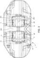
figure 3 shows an orthogonal top view of the caliper infigure 1 , i.e., in radial direction looking toward the axis of the brake disc to which said caliper is arranged in a straddling fashion; -
figure 4 shows an axonometric view of the pair of brake pads of the caliper infigure 1 with which two band springs are associated and on the plate thrust surfaces of which an antivibration, load distribution, and thermal shear plate is placed; -
figure 5 shows an axonometric view of the pair of brake pads infigure 4 without the associated band springs; -
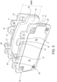
figure 6 shows an axonometric view of a plate of a brake pad infigure 4 ; -
figure 7 shows an axonometric view of the caliper body infigure 1 alone; -
figure 8 shows an axonometric view, sectioned along the centerline taken along a plane containing a radial and a circumferential direction, of the caliper body infigure 7 ; -
figure 9 shows an axonometric view, sectioned close to the caliper support surfaces of the pockets adapted to accommodate the pads, taken along a plane containing the radial and axial directions, of the caliper body infigure 7 ; -
figure 10 shows an axonometric view, sectioned close to the central bridge taken along to a plane containing the radial and axial directions, of the caliper body infigure 7 ; -
figure 11 shows an axonometric view of one of the band springs adapted to bias the pair of brake pads of the caliper infigure 1 ; -
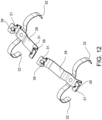
figure 12 shows an axonometric view of the pair of band springs adapted to bias the pair of brake pads of the caliper infigure 1 ; -
figure 13 shows three different steps of assembling a brake pad in a caliper body of a caliper according tofigure 1 ; -
figure 14 shows a section view of the caliper infigure 1 at the second thrust portions of band spring on a plane containing a radial direction and an axial direction, in which the elastic thrust of the band spring on the brake pads is highlighted. - . According to a general embodiment of the present invention, an assembly 1 comprises a
caliper body 2 andbrake pads Said caliper body 2 comprises twopockets pads caliper body 2 comprises twoelongated elements central bridge 203 which crosses the twopockets brake pad support plate friction material support plate support plate edge 17 having anupper edge portion 18. Eachsupport plate protuberance upper edge portion 18 and is hook-shaped defining aplate sliding surface 21 indirectly facing said rotation axis X-X. Eachsupport plate pad support surface 22 arranged substantially orthogonal to said circumferential direction C-C which extends over at least half of the predetermined radial extension MAR of saidfriction material central bridge 203 comprises at least twocentral bridge protuberances 23 separated by acentral bridge window 27, which form caliperbody sliding surfaces 24 which face said plate sliding surfaces 21. Thecaliper body 2 comprises at least two caliper support surfaces 25, 26 which face said pad support surfaces 22. - . According to an embodiment, an assembly 1 comprises a
caliper body 2 andbrake pads - . The
caliper body 2 comprises two mutually facingpockets brake pads caliper body 2 is placed straddling abraking band 7 of abrake disc 8, saidbrake pads braking surfaces braking band 7. - . Said
braking band 7 comprisesopposite braking surfaces - .
Said caliper body 2 comprises a first and a secondelongated element caliper body 2 is placed straddling thebraking band 7, face said oppositebraking surfaces - .
Said caliper body 2 comprises at least onecentral bridge 203 which connects said first and said secondelongated elements pockets - . Said
brake disc 8 comprises a rotation axis X-X which defines an axial direction A-A either coinciding with or parallel to said rotation axis X-X, a radial direction R-R orthogonal to said rotation axis X-X, and a circumferential direction C-C orthogonal to said axial direction A-A and said radial direction R-R. - . According to an embodiment, said of said
brake pads support plate friction material brake pad caliper body 2. - . According to an embodiment, said
friction material - . According to an embodiment, each
support plate thrust surface 15, an opposite frictionmaterial support surface 16, and asupport plate edge 17 which connects said thrustsurface 15 to said opposite frictionmaterial support surface 16. - . According to an embodiment, said
support plate edge 17 comprises anupper edge portion 18 facing the opposite side with respect to said rotation axis X-X. - . According to an embodiment, each
support plate protuberance upper edge portion 18 of saidsupport plate edge 17 and is hook-shaped defining aplate sliding surface 21. - . According to an embodiment, said
plate sliding surface 21 substantially and indirectly faces said rotation axis X-X. - . According to an embodiment, each
support plate pad support surface 22 arranged substantially orthogonal to said circumferential direction C-C. - . According to an embodiment, said
pad support surface 22 extends over at least 1/2 of the predetermined radial extent MAR of saidfriction material - . According to an embodiment, said at least one
central bridge 203 ofcaliper body 2 comprises at least twocentral bridge protuberances 23 forming at least two caliperbody sliding surfaces 24 which, when thebrake pads caliper body 2, face said plate sliding surfaces 21. - . According to an embodiment, said
caliper body 2 comprises at least two caliper support surfaces 25, 26 which, when thebrake pads caliper body 2, face said pad support surfaces 22. - . According to an embodiment, said at least two
central bridge protuberances 23 are separated from each other by at least onecentral bridge window 27 which allows the passage of at least one portion of said at least oneprotuberance support plates caliper body 2 bringing saidplate support surface 21 to face one of said caliperbody sliding surfaces 24 and bringing saidpad support surface 22 to face one of said caliper support surfaces 25, 26. - . According to an embodiment, said
plate sliding surface 21 faces saidupper edge portion 18 of thesupport plate edge 17. - . According to an embodiment, said
plate sliding surface 21 is arranged as an undercut with respect to saidsupport plate protuberance - . According to an embodiment, said at least one
support plate protuberance pad friction material caliper body 2 is mounted straddling thebraking band 7. - . According to an embodiment, said at least one
pad support surface 22 extends in the radial direction and extends at least as much as said friction material with its predetermined radial extension of friction material MAR. - . According to an embodiment, said caliper support surfaces are at least two caliper support surfaces 24, 25 and are arranged on opposite sides, one for each
elongated element - . According to an embodiment, said
caliper body 2 is a body in a single piece. According to an embodiment, said caliper body is made in two pieces, for example joined together be means of studs or bolts. - . According to an embodiment, said
central bridge 203 of caliper body is a single body with said first and said secondelongated elements - . According to an embodiment, two
support plate protuberances support plate - . According to an embodiment, two
support plate protuberances support plate support plate protuberances - . According to an embodiment, said
central bridge 203 comprises fourcentral bridge protuberances 23, arranged in pairs from opposite orientations of thecentral bridge 203. - . According to an embodiment, said
caliper support surface caliper body pocket respective brake pad caliper body pocket caliper body 2 during a braking action. - . According to an embodiment, said at least one
pad support surface 22 consists of two opposite pad support surfaces 22 to allow thebrake pad caliper body 2 during a forward and reverse braking action of the vehicle which features saidcaliper body 2. - . According to an embodiment, said assembly 1 further comprises at least one
band spring 28 shaped to be arranged straddling thebrake disc 8 to apply an elastic action to at least one of saidbrake pads brake disc 8. - . According to an embodiment, said at least one
brake pad support plate friction material support plate plate edge 17 which forms at least onethrust portion 29. - . According to an embodiment, said
band spring 28 comprises a band-shapedspring body 30. - . According to an embodiment, said
band spring 28 comprises at least twospring portions - a
first coupling portion 31 adapted to couple saidband spring 28 to thecaliper body 2; - a
second thrust portion 32 adapted to apply said elastic action to said thrustportion 29 of said at least onebrake pad brake pad brake disc 8 in the axial direction A-A and the radial direction R-R. - . According to an embodiment, said at least one
band spring 28 comprises a firstspring body band 33 comprising afirst connection portion 34 from which twofirst spring arms 35 move away. - . According to an embodiment, a second
spring body band 36 comprises asecond connection portion 37 from which twosecond spring arms 38 move away. - . According to an embodiment, said
first connection portion 34 of said firstspring body band 33 is connected to saidsecond connection portion 37 of said secondspring body band 36 so as to arrange said twofirst spring arms 35 orthogonal to said twosecond spring arms 38. - . According to an embodiment, said
first coupling portion 31 is shaped so as to be snap-coupled to saidcaliper body 2. - . According to an embodiment, said
first coupling portion 31 is shaped forming a through-window 39 of first coupling portion. - . Said
first coupling portion 31 is shaped formingindependent arms 40 projecting in a cantilevered fashion when theband spring 28 is not mounted to thecaliper body 2. - . According to an embodiment, said second thrust
portion 32, when supported under operating conditions by said at least onepad second thrust portion 32 and said axial direction A-A and forming a predetermined angle A2 between saidsecond thrust portion 32 and said radial direction R-R. - . According to an embodiment, said band spring consist of two band springs 28 placed on either side of the
central bridge 203. - . The present invention also relates to a method of assembling a
brake pad brake caliper 2. - . This method includes the following steps:
- providing an assembly 1 as defined in any one of the embodiments described above;
- inserting, substantially in the radial direction R-R, the
brake pad caliper body 2 on the opposite side of thecenter bridge 203, by aligning the at least oneplate protuberance central bridge window 27, so that theplate protuberance center bridge protuberances 23; - sliding the
brake pad caliper body pocket surface 15 thereof faces the caliper body and the at least oneplate sliding surface 21 faces the caliperbody sliding surface 24 and the at least onepad support surface 22 faces the at least onecaliper support surface - . According to a further constructional variant of the aforesaid method, there are included the further steps of:
- providing a
band spring 28 according to any one ofclaims 11 to 15; - inserting said
band spring 28 by snap-coupling saidfirst coupling portion 31 to saidcaliper body 2 and supporting saidsecond thrust portion 32 on said thrustportion 29 of the plate edge. -
- 1
- caliper body assembly
- 2
- caliper body
- 3
- brake pad
- 4
- brake pad
- 5
- pocket in caliper body for housing brake pad
- 6
- pocket in caliper body for housing brake pad
- 7
- braking band
- 8
- brake disc
- 9
- braking band braking surface
- 10
- braking band braking surface
- 11
- pad support plate
- 12
- pad support plate
- 13
- pad friction material
- 14
- pad friction material
- 15
- plate thrust surface
- 16
- friction material support surface of plate
- 17
- support plate edge
- 18
- upper edge portion of support plate edge
- 19
- support plate protuberance
- 20
- support plate protuberance
- 21
- plate sliding surface
- 22
- pad support surface
- 23
- central bridge protuberance
- 24
- caliper body sliding surface
- 25
- caliper support surface
- 26
- caliper support surface
- 27
- central bridge window
- 28
- band spring
- 29
- thrust portion of support plate edge
- 30
- band-shaped spring body
- 31
- first spring coupling portion
- 32
- second spring thrust portion
- 33
- first spring body band
- 34
- first spring connection portion
- 35
- first spring arms
- 36
- second spring body band
- 37
- second connection portion
- 38
- second spring arms
- 39
- through-window of first coupling portion
- 40
- independent arms
- 201
- first elongated element of caliper body
- 202
- second elongated element of caliper body
- 203
- central bridge of caliper body
- X-X
- rotation and symmetry axis of disc brake disc
- A_A
- axial direction
- R-R
- radial direction
- C-C
- circumferential direction
- MAR
- radial extension of the pad friction material
Claims (17)
- An assembly (1) of caliper body (2) and brake pads (3, 4), wherein the caliper body (2) comprises two pockets (5, 6) facing each other, which receive said two brake pads (3, 4) so that, when the caliper body (2) is placed straddling a braking band (7) of a brake disc (8), where said braking band (7) comprises opposite braking surfaces (9, 10), said brake pads (3, 4) face said opposite braking surfaces (9, 10) of said braking band (7); and whereinsaid caliper body (2) comprises a first and a second elongated element (201, 202), which, when the caliper body (2) is placed straddling the braking band (7), face said opposite braking surfaces (9, 10); and whereinsaid caliper body (2) comprises at least one central bridge (203) which connects said first and said second elongated elements (201, 202) crossing said two pockets (5, 6);said brake disc (8) comprises a rotation axis (X-X), which defines an axial direction (A-A), either coinciding with or parallel to said rotation axis (X-X), a radial direction (R-R) orthogonal to said rotation axis (X-X), and a circumferential direction (C-C) orthogonal to said axial direction (A-A) and said radial direction (R-R);each of said brake pads (3, 4) comprises a support plate (11, 12) adapted to support a friction material (13, 14) and support the brake pad (3, 4) at said caliper body (2); and whereinsaid friction material (13, 14) comprises a predetermined radial extension (MAR);each support plate (11, 12) comprises a thrust surface (15), an opposite friction material support surface (16), and a support plate edge (17), which connects said thrust surface (15) to said opposite friction material support surface (16); and whereinsaid support plate edge (17) comprises an upper edge portion (18) facing the opposite side with respect to said rotation axis (XX); and whereineach support plate (11, 12) comprises at least one protuberance (19, 20) projecting from said upper edge portion (18) of said support plate edge (17) and is hook-shaped defining a plate sliding surface (21); wherein said plate sliding surface (21) substantially faces said rotation axis (X-X) indirectly;each support plate (11, 12) comprises at least one pad support surface (22) arranged substantially orthogonal to said circumferential direction (C-C); wherein said pad support surface (22) extends over at least 1/2 of the predetermined radial extension (MAR) of said friction material (13, 14); and whereinsaid at least one central bridge (203) of caliper body (2) comprises at least two central bridge protuberances (23) forming at least two caliper body sliding surfaces (24) which, when the brake pads (3, 4) are mounted in said caliper body (2), face said plate sliding surfaces (21); and whereinsaid caliper body (2) comprises at least two caliper support surfaces (25, 26) which, when the brake pads (3, 4) are mounted in said caliper body (2), face said pad support surfaces (22);said at least two central bridge protuberances (23) are separated from each other by at least one central bridge window (27) which allows at least one portion of said at least one bridge protuberance (19, 20) to pass in order to allow mounting each of said at least two support plates (11, 12) in said caliper body (2) bringing said plate resting surface (21) to face one of said caliper body sliding surfaces (24) and bringing said pad support surface (22) to face one of said caliper support surfaces (25, 26).
- An assembly (1) according to claim 1, whereinsaid plate sliding surface (21) faces said upper edge portion (18) of the support plate edge (17);or whereinsaid plate sliding surface (21) is arranged as an undercut with respect to said plate support protuberance (19, 20).
- An assembly (1) according to any one of the preceding claims, wherein
said at least one support plate protuberance (19, 20) is placed radially outside the pad friction material (13, 14) on the opposite side with respect to the rotation axis (X-X) when the caliper body (2) is mounted straddling the braking band (7). - An assembly (1) according to any one of the preceding claims, wherein
said at least one pad support surface (22) extends in the radial direction and extends at least as much as said friction material with the predetermined radial extension of friction material (MAR). - An assembly (1) according to any one of the preceding claims, wherein
said caliper support surfaces are at least two caliper support surfaces (24, 25) and are arranged on opposite sides, one for each elongated element (201, 202). - An assembly (1) according to any one of the preceding claims, whereinsaid caliper body (2) is a one-piece body;or whereinsaid caliper body (2) is made in two parts;or whereinsaid central bridge (203) of caliper body is a single body with said first and said second elongated elements (201, 202) of caliper body.
- An assembly (1) according to any one of the preceding claims, whereintwo support plate protuberances (19, 20) are provided for each support plate (11, 12);or whereintwo support plate protuberances (19, 20) are provided for each support plate (11, 12), and these two support plate protuberances (19, 20) face each other or are mutually specularly arranged.
- An assembly (1) according to any one of the preceding claims, wherein
said central bridge (203) comprises four central bridge protuberances (23), arranged in pairs from opposite orientations of the central bridge (203). - An assembly (1) according to any one of the preceding claims, wherein
said caliper support surface (25, 26) consists of at least two caliper support surfaces (25, 26) each placed to delimit a caliper body pocket (5, 6) to house the respective brake pad (3, 4), delimiting said caliper body pocket (5,6) which allows the pad to abut against the caliper body (2) during a braking action. - An assembly (1) according to any one of the preceding claims, wherein
said at least one pad support surface (22) consists of two opposite pad support surfaces (22) to allow the brake pad (3, 4) to abut against the caliper body (2) during a forward and reverse braking action of the vehicle which features said caliper body (2). - An assembly (1) according to any one of the preceding claims, wherein
said assembly (1) further comprises at least one band spring (28) shaped to be arranged straddling the brake disc (8) to apply an elastic action to at least one of said brake pads (3, 4) to bias it away from said brake disc (8); wherein- said at least one brake pad (3, 4) comprises said support plate (11, 12), which supports said friction material (13, 14), said support plate (11, 12) comprises said plate edge (17) which forms at least one thrust portion (29);- said band spring (28) comprises a band-shaped spring body (30);- said band spring (28) comprises at least two spring portions (31, 32) at least two of which are mutually distinct, namely- a first coupling portion (31) adapted to couple said band spring (28) to the caliper body (2);- a second thrust portion (32) adapted to apply said elastic action to said thrust portion (29) of said at least one brake pad (3, 4) biasing said brake pad (3, 4) at least away from said brake disc (8) in an axial direction (A-A) and a radial direction (R-R). - An assembly (1) according to the preceding claim, whereinat least one band spring (28) comprises a first spring body band (33) comprising a first connection portion (34) from which two first spring arms (35) move away; and whereina second spring body band (36) comprising a second connection portion (37) from which two second spring arms (38) move away; and wherein said first connection portion (34) of said first spring body band (33) is connected to said second connection portion (37) of said second spring body band (36) to arrange said two first spring arms (35) orthogonal to said two second spring arms (38).
- An assembly (1) according to claim 11 or 12, whereinsaid first coupling portion (31) is shaped so as to be snap coupled to said caliper body (2);and/or whereinsaid first coupling portion (31) is shaped forming a through-window of the first coupling portion (39);or whereinsaid first coupling portion (31) is shaped forming independent arms (40) overhangingly projecting when the band spring (28) is not mounted to the caliper body (2).
- An assembly (1) according to claim 11 or 12 or 13, wherein
said second thrust portion (32), when resting onto said at least one pad (3, 4) in operating conditions, is arranged to be inclined with respect to said axial direction (A-A) as well as with respect to said radial direction (R-R), forming a predetermined angle (A1) between said second thrust portion (32) and said axial direction (A-A) and forming a predetermined angle (A2) between said second thrust portion (32) and said radial direction (R-R). - An assembly (1) according to any one of claims 11 to 14, wherein said band spring consist of two band springs (28) placed on either side of the central bridge (203).
- A method of mounting a brake pad (3, 4) to a caliper body (2), wherein the following steps are comprised:- providing an assembly (1) according to any one of claims 1 to 15;- inserting substantially in the radial direction (R-R) the brake pad (3, 4) into the caliper body (2) on the opposite side of the center bridge (203), aligning the at least one plate protuberance (19, 20) with the central bridge window (27), so that the plate protuberance (19, 20) passes radially beyond the center bridge protuberances (23);- sliding the brake pad (3, 4) in the axial direction (A-A) by inserting it into the respective caliper body pocket (5, 6), so that the plate thrust surface (15) thereof faces the caliper body and the at least one plate thrust surface (21) faces the caliper body sliding surface (24) and the at least one pad support surface (22) faces the at least one caliper support surface (25, 26).
- A method according to claim 16, wherein there are comprised the further steps of:- providing a band spring (28) according to any one of claims 11 to 15;- inserting said band spring (28) by snap-coupling said first coupling portion (31) to said caliper body (2) and supporting said second thrust portion (32) on said thrust portion (29) of the plate edge.
Applications Claiming Priority (1)
| Application Number | Priority Date | Filing Date | Title |
|---|---|---|---|
| IT202300015900 | 2023-07-27 |
Publications (2)
| Publication Number | Publication Date |
|---|---|
| EP4497962A1 true EP4497962A1 (en) | 2025-01-29 |
| EP4497962B1 EP4497962B1 (en) | 2025-09-10 |
Family
ID=88290666
Family Applications (1)
| Application Number | Title | Priority Date | Filing Date |
|---|---|---|---|
| EP24191223.7A Active EP4497962B1 (en) | 2023-07-27 | 2024-07-26 | Caliper body and brake pad assembly |
Country Status (3)
| Country | Link |
|---|---|
| US (1) | US20250035174A1 (en) |
| EP (1) | EP4497962B1 (en) |
| CN (1) | CN119373813A (en) |
Citations (19)
| Publication number | Priority date | Publication date | Assignee | Title |
|---|---|---|---|---|
| US3605956A (en) | 1968-08-29 | 1971-09-20 | Itt | Combined cover and brake pad retainer for disk brakes |
| US4046233A (en) | 1975-02-01 | 1977-09-06 | Girling Limited | Sliding caliper disc brake |
| GB1506709A (en) | 1974-04-02 | 1978-04-12 | Girling Ltd | Vehicle brakes |
| US4200173A (en) | 1978-08-01 | 1980-04-29 | Kelsey-Hayes Company | Sliding caliper disc brake |
| GB1585159A (en) | 1976-10-06 | 1981-02-25 | Girling Ltd | Friction pad assemblies for vehicle disc brakes |
| FR2517399A1 (en) | 1981-11-30 | 1983-06-03 | Dba | DISC BRAKE AND SKATE FOR SUCH BRAKE |
| US4498564A (en) | 1981-09-18 | 1985-02-12 | Tokico Ltd. | Disc brake subassembly having friction pad retaining means |
| EP0135696A1 (en) | 1983-08-31 | 1985-04-03 | Rockwell International Corporation | Disc brake friction pad and stabilizing support |
| EP0248385A1 (en) | 1986-06-04 | 1987-12-09 | LUCAS INDUSTRIES public limited company | Disc brake and leaf spring for use in this disc brake |
| US4823920A (en) | 1988-05-02 | 1989-04-25 | Kelsey-Hayes Company | Sliding caliper disc brake and brake shoe assembly therefor |
| JP2001323953A (en) | 2000-05-17 | 2001-11-22 | Nisshinbo Ind Inc | Disc brake device |
| EP1898114A1 (en) * | 2006-09-02 | 2008-03-12 | BPW Bergische Achsen KG | Brake lining for vehicle disc brakes |
| EP1963701A1 (en) * | 2005-12-19 | 2008-09-03 | Freni Brembo S.P.A. | Disc brake caliper |
| CN204200914U (en) | 2014-08-29 | 2015-03-11 | 长城汽车股份有限公司 | A kind of brake calipers |
| US20170138426A1 (en) * | 2015-11-12 | 2017-05-18 | Bendix Spicer Foundation Brake Llc | Disc Brake and Set of Brake Pads |
| US9765832B2 (en) * | 2015-01-28 | 2017-09-19 | Meritor Heavy Vehicle Braking Systems (Uk) Limited | Disc brake |
| US20180106313A1 (en) * | 2015-06-15 | 2018-04-19 | Knorr-Bremse Systeme Fuer Nutzfahrzeuge Gmbh | Disc Brake for a Commercial Vehicle and Brake Pad Set |
| EP3810952A1 (en) * | 2018-06-20 | 2021-04-28 | Freni Brembo S.p.A. | Spring for friction pads in a disc brake caliper |
| US20230108312A1 (en) * | 2020-02-20 | 2023-04-06 | Volvo Truck Corporation | Brake pad retainer system, brake pad, and vehicle |
-
2024
- 2024-07-25 US US18/783,769 patent/US20250035174A1/en active Pending
- 2024-07-26 EP EP24191223.7A patent/EP4497962B1/en active Active
- 2024-08-23 CN CN202411168814.6A patent/CN119373813A/en active Pending
Patent Citations (19)
| Publication number | Priority date | Publication date | Assignee | Title |
|---|---|---|---|---|
| US3605956A (en) | 1968-08-29 | 1971-09-20 | Itt | Combined cover and brake pad retainer for disk brakes |
| GB1506709A (en) | 1974-04-02 | 1978-04-12 | Girling Ltd | Vehicle brakes |
| US4046233A (en) | 1975-02-01 | 1977-09-06 | Girling Limited | Sliding caliper disc brake |
| GB1585159A (en) | 1976-10-06 | 1981-02-25 | Girling Ltd | Friction pad assemblies for vehicle disc brakes |
| US4200173A (en) | 1978-08-01 | 1980-04-29 | Kelsey-Hayes Company | Sliding caliper disc brake |
| US4498564A (en) | 1981-09-18 | 1985-02-12 | Tokico Ltd. | Disc brake subassembly having friction pad retaining means |
| FR2517399A1 (en) | 1981-11-30 | 1983-06-03 | Dba | DISC BRAKE AND SKATE FOR SUCH BRAKE |
| EP0135696A1 (en) | 1983-08-31 | 1985-04-03 | Rockwell International Corporation | Disc brake friction pad and stabilizing support |
| EP0248385A1 (en) | 1986-06-04 | 1987-12-09 | LUCAS INDUSTRIES public limited company | Disc brake and leaf spring for use in this disc brake |
| US4823920A (en) | 1988-05-02 | 1989-04-25 | Kelsey-Hayes Company | Sliding caliper disc brake and brake shoe assembly therefor |
| JP2001323953A (en) | 2000-05-17 | 2001-11-22 | Nisshinbo Ind Inc | Disc brake device |
| EP1963701A1 (en) * | 2005-12-19 | 2008-09-03 | Freni Brembo S.P.A. | Disc brake caliper |
| EP1898114A1 (en) * | 2006-09-02 | 2008-03-12 | BPW Bergische Achsen KG | Brake lining for vehicle disc brakes |
| CN204200914U (en) | 2014-08-29 | 2015-03-11 | 长城汽车股份有限公司 | A kind of brake calipers |
| US9765832B2 (en) * | 2015-01-28 | 2017-09-19 | Meritor Heavy Vehicle Braking Systems (Uk) Limited | Disc brake |
| US20180106313A1 (en) * | 2015-06-15 | 2018-04-19 | Knorr-Bremse Systeme Fuer Nutzfahrzeuge Gmbh | Disc Brake for a Commercial Vehicle and Brake Pad Set |
| US20170138426A1 (en) * | 2015-11-12 | 2017-05-18 | Bendix Spicer Foundation Brake Llc | Disc Brake and Set of Brake Pads |
| EP3810952A1 (en) * | 2018-06-20 | 2021-04-28 | Freni Brembo S.p.A. | Spring for friction pads in a disc brake caliper |
| US20230108312A1 (en) * | 2020-02-20 | 2023-04-06 | Volvo Truck Corporation | Brake pad retainer system, brake pad, and vehicle |
Also Published As
| Publication number | Publication date |
|---|---|
| EP4497962B1 (en) | 2025-09-10 |
| US20250035174A1 (en) | 2025-01-30 |
| CN119373813A (en) | 2025-01-28 |
Similar Documents
| Publication | Publication Date | Title |
|---|---|---|
| US3915263A (en) | Disc brake caliper and support structure | |
| EP0851139B1 (en) | Disk brake | |
| EP4160043B1 (en) | Spring, spring assembly and brake pad, caliper body assembly | |
| EP0161200A1 (en) | Brake disk and keyslot reinforcements therefor | |
| JPH05193466A (en) | Spot type disc brake | |
| EP0703378B1 (en) | Disc brake friction pad and retention system | |
| US4310075A (en) | Disc brake | |
| US4352414A (en) | Friction pad and support for a disc brake | |
| US20040195059A1 (en) | Disc brake rotor mounting system | |
| EP4497962B1 (en) | Caliper body and brake pad assembly | |
| US7014018B2 (en) | Vehicle braking device | |
| US7228946B2 (en) | Brake disc for a disc brake | |
| EP4107405B1 (en) | Brake pad retainer system, brake pad and vehicle | |
| US4609078A (en) | Spring entrapment of split wedge floatation device | |
| EP1247027B1 (en) | Brake assembly | |
| EP1299656B1 (en) | Arrangement for connecting a brake disc on a driver | |
| EP0494159B1 (en) | Center loop anti-rattle spring | |
| EP0135696B1 (en) | Disc brake friction pad and stabilizing support | |
| EP0143170B1 (en) | Disc brake friction pad support and biasing assembly | |
| EP0143941B1 (en) | Spring entrapment of split wedge floatation device | |
| EP1408252B1 (en) | Multi-disc brake | |
| EP0216534B1 (en) | Improvements relating to wheel mounted discs | |
| US4516666A (en) | Disc brake anti-rattle means | |
| EP0139890B1 (en) | Friction pad and support for a disc brake | |
| US7216745B2 (en) | Mounting friction elements to disc brakes |
Legal Events
| Date | Code | Title | Description |
|---|---|---|---|
| PUAI | Public reference made under article 153(3) epc to a published international application that has entered the european phase |
Free format text: ORIGINAL CODE: 0009012 |
|
| STAA | Information on the status of an ep patent application or granted ep patent |
Free format text: STATUS: THE APPLICATION HAS BEEN PUBLISHED |
|
| AK | Designated contracting states |
Kind code of ref document: A1 Designated state(s): AL AT BE BG CH CY CZ DE DK EE ES FI FR GB GR HR HU IE IS IT LI LT LU LV MC ME MK MT NL NO PL PT RO RS SE SI SK SM TR |
|
| STAA | Information on the status of an ep patent application or granted ep patent |
Free format text: STATUS: REQUEST FOR EXAMINATION WAS MADE |
|
| 17P | Request for examination filed |
Effective date: 20250211 |
|
| GRAP | Despatch of communication of intention to grant a patent |
Free format text: ORIGINAL CODE: EPIDOSNIGR1 |
|
| STAA | Information on the status of an ep patent application or granted ep patent |
Free format text: STATUS: GRANT OF PATENT IS INTENDED |
|
| INTG | Intention to grant announced |
Effective date: 20250521 |
|
| GRAS | Grant fee paid |
Free format text: ORIGINAL CODE: EPIDOSNIGR3 |
|
| GRAA | (expected) grant |
Free format text: ORIGINAL CODE: 0009210 |
|
| STAA | Information on the status of an ep patent application or granted ep patent |
Free format text: STATUS: THE PATENT HAS BEEN GRANTED |
|
| AK | Designated contracting states |
Kind code of ref document: B1 Designated state(s): AL AT BE BG CH CY CZ DE DK EE ES FI FR GB GR HR HU IE IS IT LI LT LU LV MC ME MK MT NL NO PL PT RO RS SE SI SK SM TR |
|
| REG | Reference to a national code |
Ref country code: GB Ref legal event code: FG4D |
|
| REG | Reference to a national code |
Ref country code: CH Ref legal event code: EP |
|
| REG | Reference to a national code |
Ref country code: DE Ref legal event code: R096 Ref document number: 602024000636 Country of ref document: DE |
|
| REG | Reference to a national code |
Ref country code: IE Ref legal event code: FG4D |
|
| PG25 | Lapsed in a contracting state [announced via postgrant information from national office to epo] |
Ref country code: NO Free format text: LAPSE BECAUSE OF FAILURE TO SUBMIT A TRANSLATION OF THE DESCRIPTION OR TO PAY THE FEE WITHIN THE PRESCRIBED TIME-LIMIT Effective date: 20251210 |
|
| REG | Reference to a national code |
Ref country code: LT Ref legal event code: MG9D |
|
| PG25 | Lapsed in a contracting state [announced via postgrant information from national office to epo] |
Ref country code: FI Free format text: LAPSE BECAUSE OF FAILURE TO SUBMIT A TRANSLATION OF THE DESCRIPTION OR TO PAY THE FEE WITHIN THE PRESCRIBED TIME-LIMIT Effective date: 20250910 |
|
| REG | Reference to a national code |
Ref country code: NL Ref legal event code: MP Effective date: 20250910 |
|
| PG25 | Lapsed in a contracting state [announced via postgrant information from national office to epo] |
Ref country code: HR Free format text: LAPSE BECAUSE OF FAILURE TO SUBMIT A TRANSLATION OF THE DESCRIPTION OR TO PAY THE FEE WITHIN THE PRESCRIBED TIME-LIMIT Effective date: 20250910 |
|
| PG25 | Lapsed in a contracting state [announced via postgrant information from national office to epo] |
Ref country code: GR Free format text: LAPSE BECAUSE OF FAILURE TO SUBMIT A TRANSLATION OF THE DESCRIPTION OR TO PAY THE FEE WITHIN THE PRESCRIBED TIME-LIMIT Effective date: 20251211 |
|
| PG25 | Lapsed in a contracting state [announced via postgrant information from national office to epo] |
Ref country code: SE Free format text: LAPSE BECAUSE OF FAILURE TO SUBMIT A TRANSLATION OF THE DESCRIPTION OR TO PAY THE FEE WITHIN THE PRESCRIBED TIME-LIMIT Effective date: 20250910 |
|
| PG25 | Lapsed in a contracting state [announced via postgrant information from national office to epo] |
Ref country code: LV Free format text: LAPSE BECAUSE OF FAILURE TO SUBMIT A TRANSLATION OF THE DESCRIPTION OR TO PAY THE FEE WITHIN THE PRESCRIBED TIME-LIMIT Effective date: 20250910 |
|
| PG25 | Lapsed in a contracting state [announced via postgrant information from national office to epo] |
Ref country code: PL Free format text: LAPSE BECAUSE OF FAILURE TO SUBMIT A TRANSLATION OF THE DESCRIPTION OR TO PAY THE FEE WITHIN THE PRESCRIBED TIME-LIMIT Effective date: 20250910 Ref country code: BG Free format text: LAPSE BECAUSE OF FAILURE TO SUBMIT A TRANSLATION OF THE DESCRIPTION OR TO PAY THE FEE WITHIN THE PRESCRIBED TIME-LIMIT Effective date: 20250910 |
|
| PG25 | Lapsed in a contracting state [announced via postgrant information from national office to epo] |
Ref country code: RS Free format text: LAPSE BECAUSE OF FAILURE TO SUBMIT A TRANSLATION OF THE DESCRIPTION OR TO PAY THE FEE WITHIN THE PRESCRIBED TIME-LIMIT Effective date: 20251210 |
|
| PG25 | Lapsed in a contracting state [announced via postgrant information from national office to epo] |
Ref country code: ES Free format text: LAPSE BECAUSE OF FAILURE TO SUBMIT A TRANSLATION OF THE DESCRIPTION OR TO PAY THE FEE WITHIN THE PRESCRIBED TIME-LIMIT Effective date: 20250910 |
|
| REG | Reference to a national code |
Ref country code: AT Ref legal event code: MK05 Ref document number: 1836171 Country of ref document: AT Kind code of ref document: T Effective date: 20250910 |
|
| PG25 | Lapsed in a contracting state [announced via postgrant information from national office to epo] |
Ref country code: NL Free format text: LAPSE BECAUSE OF FAILURE TO SUBMIT A TRANSLATION OF THE DESCRIPTION OR TO PAY THE FEE WITHIN THE PRESCRIBED TIME-LIMIT Effective date: 20250910 |
|
| PG25 | Lapsed in a contracting state [announced via postgrant information from national office to epo] |
Ref country code: SM Free format text: LAPSE BECAUSE OF FAILURE TO SUBMIT A TRANSLATION OF THE DESCRIPTION OR TO PAY THE FEE WITHIN THE PRESCRIBED TIME-LIMIT Effective date: 20250910 |
|
| PG25 | Lapsed in a contracting state [announced via postgrant information from national office to epo] |
Ref country code: AT Free format text: LAPSE BECAUSE OF FAILURE TO SUBMIT A TRANSLATION OF THE DESCRIPTION OR TO PAY THE FEE WITHIN THE PRESCRIBED TIME-LIMIT Effective date: 20250910 |
|
| PG25 | Lapsed in a contracting state [announced via postgrant information from national office to epo] |
Ref country code: IT Free format text: LAPSE BECAUSE OF FAILURE TO SUBMIT A TRANSLATION OF THE DESCRIPTION OR TO PAY THE FEE WITHIN THE PRESCRIBED TIME-LIMIT Effective date: 20250910 |
|
| PG25 | Lapsed in a contracting state [announced via postgrant information from national office to epo] |
Ref country code: IS Free format text: LAPSE BECAUSE OF FAILURE TO SUBMIT A TRANSLATION OF THE DESCRIPTION OR TO PAY THE FEE WITHIN THE PRESCRIBED TIME-LIMIT Effective date: 20260110 |
|
| PG25 | Lapsed in a contracting state [announced via postgrant information from national office to epo] |
Ref country code: CZ Free format text: LAPSE BECAUSE OF FAILURE TO SUBMIT A TRANSLATION OF THE DESCRIPTION OR TO PAY THE FEE WITHIN THE PRESCRIBED TIME-LIMIT Effective date: 20250910 Ref country code: PT Free format text: LAPSE BECAUSE OF FAILURE TO SUBMIT A TRANSLATION OF THE DESCRIPTION OR TO PAY THE FEE WITHIN THE PRESCRIBED TIME-LIMIT Effective date: 20260112 |
|
| PG25 | Lapsed in a contracting state [announced via postgrant information from national office to epo] |
Ref country code: SK Free format text: LAPSE BECAUSE OF FAILURE TO SUBMIT A TRANSLATION OF THE DESCRIPTION OR TO PAY THE FEE WITHIN THE PRESCRIBED TIME-LIMIT Effective date: 20250910 Ref country code: EE Free format text: LAPSE BECAUSE OF FAILURE TO SUBMIT A TRANSLATION OF THE DESCRIPTION OR TO PAY THE FEE WITHIN THE PRESCRIBED TIME-LIMIT Effective date: 20250910 |