EP4497954A1 - Hydraulic rotary gearless actuator - Google Patents
Hydraulic rotary gearless actuator Download PDFInfo
- Publication number
- EP4497954A1 EP4497954A1 EP24190412.7A EP24190412A EP4497954A1 EP 4497954 A1 EP4497954 A1 EP 4497954A1 EP 24190412 A EP24190412 A EP 24190412A EP 4497954 A1 EP4497954 A1 EP 4497954A1
- Authority
- EP
- European Patent Office
- Prior art keywords
- tracks
- cylinder
- output
- gearless
- piston
- Prior art date
- Legal status (The legal status is an assumption and is not a legal conclusion. Google has not performed a legal analysis and makes no representation as to the accuracy of the status listed.)
- Pending
Links
Images

Classifications
-
- F—MECHANICAL ENGINEERING; LIGHTING; HEATING; WEAPONS; BLASTING
- F15—FLUID-PRESSURE ACTUATORS; HYDRAULICS OR PNEUMATICS IN GENERAL
- F15B—SYSTEMS ACTING BY MEANS OF FLUIDS IN GENERAL; FLUID-PRESSURE ACTUATORS, e.g. SERVOMOTORS; DETAILS OF FLUID-PRESSURE SYSTEMS, NOT OTHERWISE PROVIDED FOR
- F15B15/00—Fluid-actuated devices for displacing a member from one position to another; Gearing associated therewith
- F15B15/02—Mechanical layout characterised by the means for converting the movement of the fluid-actuated element into movement of the finally-operated member
- F15B15/06—Mechanical layout characterised by the means for converting the movement of the fluid-actuated element into movement of the finally-operated member for mechanically converting rectilinear movement into non- rectilinear movement
- F15B15/068—Mechanical layout characterised by the means for converting the movement of the fluid-actuated element into movement of the finally-operated member for mechanically converting rectilinear movement into non- rectilinear movement the motor being of the helical type
-
- F—MECHANICAL ENGINEERING; LIGHTING; HEATING; WEAPONS; BLASTING
- F15—FLUID-PRESSURE ACTUATORS; HYDRAULICS OR PNEUMATICS IN GENERAL
- F15B—SYSTEMS ACTING BY MEANS OF FLUIDS IN GENERAL; FLUID-PRESSURE ACTUATORS, e.g. SERVOMOTORS; DETAILS OF FLUID-PRESSURE SYSTEMS, NOT OTHERWISE PROVIDED FOR
- F15B15/00—Fluid-actuated devices for displacing a member from one position to another; Gearing associated therewith
- F15B15/02—Mechanical layout characterised by the means for converting the movement of the fluid-actuated element into movement of the finally-operated member
- F15B15/06—Mechanical layout characterised by the means for converting the movement of the fluid-actuated element into movement of the finally-operated member for mechanically converting rectilinear movement into non- rectilinear movement
-
- F—MECHANICAL ENGINEERING; LIGHTING; HEATING; WEAPONS; BLASTING
- F16—ENGINEERING ELEMENTS AND UNITS; GENERAL MEASURES FOR PRODUCING AND MAINTAINING EFFECTIVE FUNCTIONING OF MACHINES OR INSTALLATIONS; THERMAL INSULATION IN GENERAL
- F16H—GEARING
- F16H25/00—Gearings comprising primarily only cams, cam-followers and screw-and-nut mechanisms
- F16H25/18—Gearings comprising primarily only cams, cam-followers and screw-and-nut mechanisms for conveying or interconverting oscillating or reciprocating motions
- F16H25/186—Gearings comprising primarily only cams, cam-followers and screw-and-nut mechanisms for conveying or interconverting oscillating or reciprocating motions with reciprocation along the axis of oscillation
Definitions
- the present disclosure relates to actuators and, in particular, to a hydraulic rotary gearless actuator.
- a hydraulic rotary gearless actuator includes an input stage and an output stage.
- the input stage includes a piston linearly translatable within an input cylinder.
- the output stage includes first and second output cylinders defining first and second tracks, respectively, and a trunnion assembly connected to the piston and including first and second rollers engageable with the first and second tracks, respectively.
- the output stage is configured to convert linear translation of the piston into rotation of the first output cylinder relative to the second output cylinder by the trunnion assembly being driven linearly by the linear translation of the piston and the first and second rollers engaging with the first and second tracks, respectively.
- hydraulics are provided to hydraulically drive the linear translation of the piston.
- a rotary variable differential transformer calculates an angular displacement of the first output cylinder.
- the first output cylinder is a rotary cylinder and the first tracks are helical tracks
- the second output cylinder is a static cylinder, which is static relative to the input cylinder
- the second tracks are axial tracks
- the hydraulic rotary gearless actuator further includes bearings interposed between the first and second output cylinders.
- the first output cylinder and the helical tracks are disposed about the second output cylinder and the axial tracks.
- the trunnion assembly includes a central hub and multiple trunnions extending radially outwardly from the central hub and each of the trunnions includes one of the first rollers and one of the second rollers.
- the one of the first rollers is outboard of the one of the second rollers.
- a hydraulic rotary gearless actuator includes an input stage and an output stage.
- the input stage includes an input cylinder and a piston linearly translatable within the input cylinder.
- the output stage includes a first output cylinder defining first tracks, a second output cylinder defining second tracks and a trunnion assembly connected to the piston.
- the trunnion assembly includes first rollers disposed to engage with the first tracks and second rollers disposed to engage with the second tracks.
- the output stage is configured to convert linear translation of the piston into rotary movement of the first output cylinder relative to the second output cylinder by the trunnion assembly being driven linearly by the linear translation of the piston and the first and second rollers engaging with the first and second tracks, respectively.
- hydraulics are provided to hydraulically drive the linear translation of the piston.
- a rotary variable differential transformer calculates an angular displacement of the first output cylinder.
- the first output cylinder is a rotary cylinder and the first tracks are helical tracks
- the second output cylinder is a static cylinder, which is static relative to the input cylinder
- the second tracks are axial tracks
- the hydraulic rotary gearless actuator further includes bearings interposed between the first and second output cylinders.
- the first output cylinder and the helical tracks are disposed about the second output cylinder and the axial tracks.
- the trunnion assembly includes a central hub and multiple trunnions extending radially outwardly from the central hub and each of the trunnions includes one of the first rollers and one of the second rollers.
- the one of the first rollers is outboard of the one of the second rollers.
- a hydraulic rotary gearless actuator includes a hydraulic input stage and a mechanical output stage.
- the hydraulic input stage includes an input cylinder and a piston, which is hydraulically drivable to linearly translate within the input cylinder.
- the mechanical output stage includes a first output cylinder defining first tracks, a second output cylinder defining second tracks and a trunnion assembly connected to the piston.
- the trunnion assembly includes first rollers disposed to engage with the first tracks and second rollers disposed to engage with the second tracks.
- the mechanical output stage is configured to convert linear translation of the piston into rotary movement of the first output cylinder relative to the second output cylinder by the trunnion assembly being driven linearly by the linear translation of the piston and the first and second rollers engaging with the first and second tracks, respectively.
- hydraulics are provided to hydraulically drive the linear translation of the piston.
- a rotary variable differential transformer calculates an angular displacement of the first output cylinder.
- the first output cylinder is a rotary cylinder and the first tracks are helical tracks
- the second output cylinder is a static cylinder, which is static relative to the input cylinder
- the second tracks are axial tracks
- the hydraulic rotary gearless actuator further includes bearings interposed between the first and second output cylinders.
- the trunnion assembly includes a central hub and multiple trunnions extending radially outwardly from the central hub and each of the trunnions comprises one of the first rollers and one of the second rollers.
Landscapes
- Engineering & Computer Science (AREA)
- Physics & Mathematics (AREA)
- Fluid Mechanics (AREA)
- Mechanical Engineering (AREA)
- General Engineering & Computer Science (AREA)
- Actuator (AREA)
Abstract
A hydraulic rotary gearless actuator is provided. The hydraulic gearless actuator includes an input stage (110) and an output stage (120). The input stage includes a piston (112) linearly translatable within an input cylinder (111). The output stage includes first and second output cylinders (121, 123) defining first and second tracks (122, 124), respectively, and a trunnion assembly (125) connected to the piston and including first and second rollers (126, 127) engageable with the first and second tracks, respectively. The output stage is configured to convert linear translation of the piston into rotation of the first output cylinder relative to the second output cylinder by the trunnion assembly being driven linearly by the linear translation of the piston and the first and second rollers engaging with the first and second tracks, respectively.
Description
- This application claims the benefit of
U.S. Provisional Application No. 63/516,043 filed July 27, 2023 - The present disclosure relates to actuators and, in particular, to a hydraulic rotary gearless actuator.
- An experimental airliner is currently under development and uses extra-long, thin wings that are stabilized by diagonal struts. This configuration is generally referred to a transonic truss-braced wing concept. The aircraft configuration is based on research studies referred to as "Subsonic Ultra-Green Aircraft Reach (SUGAR)" which extensively studied truss-bracing and hybrid electric technologies.
- According to an aspect of the disclosure, a hydraulic rotary gearless actuator is provided. The hydraulic gearless actuator includes an input stage and an output stage. The input stage includes a piston linearly translatable within an input cylinder. The output stage includes first and second output cylinders defining first and second tracks, respectively, and a trunnion assembly connected to the piston and including first and second rollers engageable with the first and second tracks, respectively. The output stage is configured to convert linear translation of the piston into rotation of the first output cylinder relative to the second output cylinder by the trunnion assembly being driven linearly by the linear translation of the piston and the first and second rollers engaging with the first and second tracks, respectively.
- In embodiments, hydraulics are provided to hydraulically drive the linear translation of the piston.
- In embodiments, a rotary variable differential transformer calculates an angular displacement of the first output cylinder.
- In embodiments, the first output cylinder is a rotary cylinder and the first tracks are helical tracks, the second output cylinder is a static cylinder, which is static relative to the input cylinder, and the second tracks are axial tracks and the hydraulic rotary gearless actuator further includes bearings interposed between the first and second output cylinders.
- In embodiments, the first output cylinder and the helical tracks are disposed about the second output cylinder and the axial tracks.
- In embodiments, the trunnion assembly includes a central hub and multiple trunnions extending radially outwardly from the central hub and each of the trunnions includes one of the first rollers and one of the second rollers.
- In embodiments, the one of the first rollers is outboard of the one of the second rollers.
- According to an aspect of the disclosure, a hydraulic rotary gearless actuator is provided and includes an input stage and an output stage. The input stage includes an input cylinder and a piston linearly translatable within the input cylinder. The output stage includes a first output cylinder defining first tracks, a second output cylinder defining second tracks and a trunnion assembly connected to the piston. The trunnion assembly includes first rollers disposed to engage with the first tracks and second rollers disposed to engage with the second tracks. The output stage is configured to convert linear translation of the piston into rotary movement of the first output cylinder relative to the second output cylinder by the trunnion assembly being driven linearly by the linear translation of the piston and the first and second rollers engaging with the first and second tracks, respectively.
- In embodiments, hydraulics are provided to hydraulically drive the linear translation of the piston.
- In embodiments, a rotary variable differential transformer calculates an angular displacement of the first output cylinder.
- In embodiments, the first output cylinder is a rotary cylinder and the first tracks are helical tracks, the second output cylinder is a static cylinder, which is static relative to the input cylinder, and the second tracks are axial tracks and the hydraulic rotary gearless actuator further includes bearings interposed between the first and second output cylinders.
- In embodiments, the first output cylinder and the helical tracks are disposed about the second output cylinder and the axial tracks.
- In embodiments, the trunnion assembly includes a central hub and multiple trunnions extending radially outwardly from the central hub and each of the trunnions includes one of the first rollers and one of the second rollers.
- In embodiments, the one of the first rollers is outboard of the one of the second rollers.
- According to an aspect of the disclosure, a hydraulic rotary gearless actuator is provided and includes a hydraulic input stage and a mechanical output stage. The hydraulic input stage includes an input cylinder and a piston, which is hydraulically drivable to linearly translate within the input cylinder. The mechanical output stage includes a first output cylinder defining first tracks, a second output cylinder defining second tracks and a trunnion assembly connected to the piston. The trunnion assembly includes first rollers disposed to engage with the first tracks and second rollers disposed to engage with the second tracks. The mechanical output stage is configured to convert linear translation of the piston into rotary movement of the first output cylinder relative to the second output cylinder by the trunnion assembly being driven linearly by the linear translation of the piston and the first and second rollers engaging with the first and second tracks, respectively.
- In embodiments, hydraulics are provided to hydraulically drive the linear translation of the piston.
- In embodiments, a rotary variable differential transformer calculates an angular displacement of the first output cylinder.
- In embodiments, the first output cylinder is a rotary cylinder and the first tracks are helical tracks, the second output cylinder is a static cylinder, which is static relative to the input cylinder, and the second tracks are axial tracks and the hydraulic rotary gearless actuator further includes bearings interposed between the first and second output cylinders.
- In embodiments, the trunnion assembly includes a central hub and multiple trunnions extending radially outwardly from the central hub and each of the trunnions comprises one of the first rollers and one of the second rollers.
- In embodiments, the first output cylinder is disposed about the second output cylinder and, for each of the trunnions, the one of the first rollers is outboard of the one of the second rollers.
- Additional features and advantages are realized through the techniques of the present disclosure. Other embodiments and aspects of the disclosure are described in detail herein and are considered a part of the claimed technical concept. For a better understanding of the disclosure with the advantages and the features, refer to the description and to the drawings.
- For a more complete understanding of this disclosure, reference is now made to the following brief description, taken in connection with the accompanying drawings and detailed description, wherein like reference numerals represent like parts:
-
FIG. 1A is a side view of a hydraulic rotary gearless actuator in accordance with embodiments; -
FIG. 1B is an axial view of a mechanical output stage of the hydraulic rotary gearless actuator ofFIG. 1A taken along line 1-1 in accordance with embodiments; -
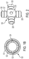
FIG. 2 is a perspective view of a trunnion assembly of the hydraulic rotary gearless actuator ofFIG. 1 in accordance with embodiments; and -
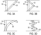
FIGS. 3A-3D are schematic illustrations of first and second track pairs of the mechanical output stage ofFIGS. 1A and1B in accordance with embodiments. - Aircraft manufacturers are currently pursuing new, thin wing concepts as part of a pursuit of carbon neutral airplanes. Recent technology reviews have identified a need for small (~ 3-4" diameter) hydraulically powered rotary actuators to this end. Presently, industry solutions are limited to rotary vane actuators which are difficult to seal.
- Thus, as will be described below, a mechanical output stage of a gearless rotary actuator is combined with a new hydraulic input stage. The mechanical output stage converts a linear translation of the input stage into rotary movement via a trunnion assembly system that utilizes rolling track rollers in set of grooves. Unlike cases in which the linear translation of input is provided by a motor driven ball-screw, the linear translation as described herein is provided directly via a hydraulic piston in a cylinder. The approach enables a magnitude increase in developed axial force generated by the input stage which enables a new level of output torque from the machine.
- With reference to
FIGS. 1A and1B , a hydraulic rotarygearless actuator 101 is provided and includes ahydraulic input stage 110, amechanical output stage 120, hydraulics 130 and a rotary variable differential transformer (RVDT) 140. Thehydraulic input stage 110 includes an input cylinder 111 and apiston 112 that is linearly translatable within the input cylinder 111. Thepiston 112 includes ahead 113 that is sealed and movable within an interior diameter of the input cylinder 111 and ashaft 114 that is movable with thehead 113. Themechanical output stage 120 includes afirst output cylinder 121, which is formed to define first tracks 122 (i.e., helical tracks; for purposes of clarity and brevity, the following description will relate to the case of thefirst tracks 122 being helical tracks), asecond output cylinder 123, which is formed to define second tracks 124 (i.e., axial tracks; for purposes of clarity and brevity, the following description will relate to the case of thesecond tracks 124 being axial tracks) and atrunnion assembly 125 that is connected to theshaft 114 of thepiston 112. Thetrunnion assembly 125 includesfirst rollers 126 andsecond rollers 127. Thefirst rollers 126 are respectively disposed to engage with corresponding ones of the first tracks 122. Thesecond rollers 127 are respectively disposed to engage with corresponding ones of the second tracks 124. - The
hydraulics 130 are disposed and configured to hydraulically drive the linear translation of thepiston 112 and may include multiple hydraulic lines on either side of thehead 113 of thepiston 112 to pressurize and de-pressurize an interior of the input cylinder 111 on the sides of thehead 113. TheRVDT 140 is disposed and configured within an RVDT zone 141 of thesecond output cylinder 123 to calculate an angular displacement of the first output cylinder 121 (i.e., the angular displacement generated by the gearless actuator). - The
mechanical output stage 120 is configured to convert linear translation of thepiston 112 into rotary movement of thefirst output cylinder 121 relative to thesecond output cylinder 123 by the action of thetrunnion assembly 125 being driven linearly by the linear translation of theshaft 114 of thepiston 112 and by the actions of the first andsecond rollers second tracks - In accordance with embodiments, the
first output cylinder 121 is a rotary cylinder and thefirst tracks 122 are the helical tracks, thesecond output cylinder 123 is a static cylinder, which is static relative to the input cylinder 111, and thesecond tracks 124 are the axial tracks and the hydraulic rotarygearless actuator 101 further includesbearings 150, such as axial bearings, interposed between thefirst output cylinder 121 and thesecond output cylinder 123. Thefirst output cylinder 121 and thefirst tracks 122 can be, but are not required to be, disposed about thesecond output cylinder 123 and the second tracks 124. - With reference to
FIG. 2 and in accordance with embodiments, thetrunnion assembly 125 includes acentral hub 210 andmultiple trunnions 220 extending radially outwardly from thecentral hub 210. Each of thetrunnions 220 can include one or more of thefirst rollers 126 and one or more of thesecond rollers 127, with the one or more of thefirst rollers 126 being outboard of the one or more of the second rollers 127 (to correspond to thefirst tracks 122 being outboard of the second tracks 124). Thetrunnion assembly 125 can include fourtrunnions 220 at uniform angular displacements in an exemplary case. Each of the one or more of thefirst rollers 126 and each of the one or more of thesecond rollers 127 can be provided as a bushing or a journal bearing. - In an operation of the hydraulic rotary
gearless actuator 101 ofFIGS. 1A and1B and thetrunnion assembly 125 ofFIGS. 1A and2 , as thepiston 112 translates linearly within the input cylinder 111, theshaft 114 drives a corresponding linear translation of thetrunnion assembly 125. During this linear translation of thetrunnion assembly 125, the engagement of thesecond rollers 127 with thesecond tracks 124 maintains an angular position of thetrunnion assembly 125 whereas the engagement of thefirst rollers 126 with thefirst tracks 122 generates rotational torque. This rotational torque can only be dissipated by rotation of thefirst output cylinder 121 relative to thesecond output cylinder 123. - With reference to
FIGS. 3A-3D , various embodiments of corresponding pairs of the first andsecond tracks mechanical output stage 120. As shown inFIG. 3A , the case in which thefirst track 122 is ahelical track 301 and the second track is anaxial track 302 is shown. As shown inFIG. 3B , the case in which thefirst track 122 is a two-strokehelical track 303 and the second track is anaxial track 302 is shown. As shown inFIG. 3C , the case in which thefirst track 122 is a non-linearhelical track 304 and the second track is anaxial track 302 is shown. As shown inFIG. 3D , the case in which thefirst track 122 is asinusoidal track 305 and the second track is anaxial track 302 is shown. - Technical effects and benefits of the present disclosure are the provision of a hydraulic rotary gearless actuator. Typically, for the given envelope of 3.4" diameter, an electrically actuated gearless actuator would be limited to an output torque window of up to 750Nm. With the features described herein. an output torque of 4000Nm is achievable and makes it possible to compete with competitor rotary vane actuators for new applications.
- The corresponding structures, materials, acts and equivalents of all means or step plus function elements in the claims below are intended to include any structure, material, or act for performing the function in combination with other claimed elements as specifically claimed. The description of the present disclosure has been presented for purposes of illustration and description, but is not intended to be exhaustive or limited to the technical concepts in the form disclosed. Many modifications and variations will be apparent to those of ordinary skill in the art without departing from the scope and spirit of the disclosure. The embodiments were chosen and described in order to best explain the principles of the disclosure and the practical application and to enable others of ordinary skill in the art to understand the disclosure for various embodiments with various modifications as are suited to the particular use contemplated.
- While the preferred embodiments to the disclosure have been described, it will be understood that those skilled in the art, both now and in the future, may make various improvements and enhancements which fall within the scope of the claims which follow. These claims should be construed to maintain the proper protection for the disclosure first described.
Claims (9)
- A hydraulic rotary gearless actuator, comprising:an input stage (110) comprising a piston (112) linearly translatable within an input cylinder (111); andan output stage (120) comprising first and second output cylinders (121, 123) defining first and second tracks (122, 1, respectively, and a trunnion assembly (125) connected to the piston and comprising first and second rollers (126, 127) engageable with the first and second tracks, respectively,the output stage being configured to convert linear translation of the piston into rotation of the first output cylinder relative to the second output cylinder by the trunnion assembly being driven linearly by the linear translation of the piston and the first and second rollers engaging with the first and second tracks, respectively.
- The hydraulic rotary gearless actuator according to claim 1, further comprising hydraulics (130) to hydraulically drive the linear translation of the piston.
- The hydraulic rotary gearless actuator according to claim 1 or 2, further comprising a rotary variable differential transformer (140) to calculate an angular displacement of the first output cylinder.
- The hydraulic rotary gearless actuator according to claim 1, 2 or 3, wherein:the first output cylinder (121) is a rotary cylinder and the first tracks (122) are helical tracks,the second output cylinder (123) is a static cylinder, which is static relative to the input cylinder, and the second tracks (124) are axial tracks, andthe hydraulic rotary gearless actuator further comprises bearings (150) interposed between the first and second output cylinders.
- The hydraulic rotary gearless actuator according to claim 4, wherein the first output cylinder and the helical tracks are disposed about the second output cylinder and the axial tracks.
- The hydraulic rotary gearless actuator according to any preceding claim, wherein:the trunnion assembly comprises a central hub (210) and multiple trunnions (220) extending radially outwardly from the central hub, andeach of the trunnions comprises one of the first rollers and one of the second rollers.
- The hydraulic rotary gearless actuator according to claim 6, wherein the one of the first rollers is outboard of the one of the second rollers.
- The hydraulic rotary gearless actuator, further comprising:
the input cylinder (111) within which the piston is linearly translatable. - The hydraulic rotary gearless actuator of claim 8, wherein the input stage is a hydraulic input stage; and
the output stage is a mechanical output stage.
Applications Claiming Priority (1)
| Application Number | Priority Date | Filing Date | Title |
|---|---|---|---|
| US202363516043P | 2023-07-27 | 2023-07-27 |
Publications (1)
| Publication Number | Publication Date |
|---|---|
| EP4497954A1 true EP4497954A1 (en) | 2025-01-29 |
Family
ID=91966964
Family Applications (1)
| Application Number | Title | Priority Date | Filing Date |
|---|---|---|---|
| EP24190412.7A Pending EP4497954A1 (en) | 2023-07-27 | 2024-07-23 | Hydraulic rotary gearless actuator |
Country Status (2)
| Country | Link |
|---|---|
| US (1) | US12454966B2 (en) |
| EP (1) | EP4497954A1 (en) |
Citations (3)
| Publication number | Priority date | Publication date | Assignee | Title |
|---|---|---|---|---|
| US3391722A (en) * | 1964-01-10 | 1968-07-09 | David R. Ligh | Motion transforming actuator particularly for hatch covers |
| EP0161919A2 (en) * | 1984-05-11 | 1985-11-21 | Deans And Lightalloys Limited | Fluid pressure actuators |
| EP0365377A1 (en) * | 1988-09-23 | 1990-04-25 | Christian Chorin | Device for converting linear movement into and vice versa oscillating movement |
Family Cites Families (16)
| Publication number | Priority date | Publication date | Assignee | Title |
|---|---|---|---|---|
| DE9413740U1 (en) * | 1994-08-25 | 1996-01-04 | AL-KO Kober AG, 89359 Kötz | Two-stage spindle drive for converting a rotary movement into a linear movement |
| US20060266146A1 (en) | 2005-05-31 | 2006-11-30 | Waide William M | Direct drive electromechanical linear actuators |
| FR2895483B1 (en) * | 2005-12-23 | 2008-10-24 | Messier Bugatti Sa | TELESCOPIC ACTUATOR WITH MAIN ROD AND AUXILIARY ROD, AND METHOD USING THE SAME |
| US8172174B2 (en) | 2008-11-13 | 2012-05-08 | Honeywell International Inc. | Hybrid electromechanical/hydromechanical actuator and actuation control system |
| FR2946618B1 (en) | 2009-06-11 | 2011-07-29 | Messier Bugatti | ACTUATOR WITH MECHANICAL OPERATION AND HYDRAULIC DAMPING. |
| GB0914576D0 (en) * | 2009-08-20 | 2009-09-30 | Airbus Operations Ltd | Apparatus for use on an aircraft |
| US8960031B2 (en) * | 2009-09-01 | 2015-02-24 | Parker-Hannifin Corporation | Aircraft stabilizer actuator |
| DE102011006679B4 (en) | 2011-03-16 | 2018-07-12 | Ferrobotics Compliant Robot Technology Gmbh | Active handling device and method for contact tasks |
| US8979019B2 (en) | 2011-07-27 | 2015-03-17 | Honeywell International Inc. | Aircraft taxi system including drive chain |
| US8844389B2 (en) | 2011-12-14 | 2014-09-30 | Woodward Hrt, Inc. | Automatically locking linear actuator |
| FR3016607B1 (en) * | 2014-01-20 | 2016-01-22 | Sagem Defense Securite | ACTUATOR FOR CONTROLLING A HORIZONTAL STABILIZATION PLAN OF AN AIRCRAFT |
| EP3072808B1 (en) * | 2015-03-26 | 2017-10-25 | Goodrich Actuation Systems SAS | Upper attachment for trimmable horizontal stabiliser actuator |
| US10822074B2 (en) | 2016-04-29 | 2020-11-03 | Parker-Hannifin Corporation | Aircraft actuator with no-back, load detent assembly |
| US10662897B2 (en) | 2017-01-18 | 2020-05-26 | Woodward, Inc. | Over-center thrust reverser primary lock |
| US10737764B2 (en) | 2018-04-13 | 2020-08-11 | The Boeing Company | Base flight control member orientation mechanism and control |
| US11460082B2 (en) | 2020-06-29 | 2022-10-04 | Akebnon Brake Industry Co., Ltd. | Self-lock high-efficient rotary to linear mechanism |
-
2023
- 2023-09-21 US US18/471,857 patent/US12454966B2/en active Active
-
2024
- 2024-07-23 EP EP24190412.7A patent/EP4497954A1/en active Pending
Patent Citations (3)
| Publication number | Priority date | Publication date | Assignee | Title |
|---|---|---|---|---|
| US3391722A (en) * | 1964-01-10 | 1968-07-09 | David R. Ligh | Motion transforming actuator particularly for hatch covers |
| EP0161919A2 (en) * | 1984-05-11 | 1985-11-21 | Deans And Lightalloys Limited | Fluid pressure actuators |
| EP0365377A1 (en) * | 1988-09-23 | 1990-04-25 | Christian Chorin | Device for converting linear movement into and vice versa oscillating movement |
Also Published As
| Publication number | Publication date |
|---|---|
| US12454966B2 (en) | 2025-10-28 |
| US20250035134A1 (en) | 2025-01-30 |
Similar Documents
| Publication | Publication Date | Title |
|---|---|---|
| EP2492192B1 (en) | Disc rotor retraction system | |
| CN106787414B (en) | A kind of integrated electromechanical servo acting device of high power density | |
| EP2440453B1 (en) | Device for actuating a control surface of an aircraft | |
| KR20170104437A (en) | Helicopter anti-torque rotor | |
| US4738415A (en) | Hinge line flight actuator | |
| JP7674842B2 (en) | Recirculating ball screw rotary actuator | |
| BR102012030301A2 (en) | AUTOMATIC LOCK ACTUATOR | |
| EP3868653B1 (en) | Rotary actuator | |
| US12454966B2 (en) | Hydraulic rotary gearless actuator | |
| US8590834B1 (en) | Aircraft control surface actuation system with helical actuation path | |
| CN219802072U (en) | Multi-stage step actuating motor electric actuator | |
| US20250146563A1 (en) | Fault tolerant rotary ema | |
| CN212305001U (en) | A compact electromechanical actuator | |
| CA2529534C (en) | Fault-tolerant electro-mechanical actuator | |
| EP3081485B1 (en) | Actuator for use in a rotor blade | |
| EP4269234A1 (en) | Skewed roller impeller cage for use with a rotary no-back device | |
| CN115940498A (en) | Centralized step-by-step action multi-stage electromechanical actuator | |
| CN1980010B (en) | Fault-tolerant electromechanical actuator | |
| CN112271864A (en) | Dual-redundancy speed comprehensive electromechanical actuator for controlling main rotor of unmanned helicopter | |
| CN121341460B (en) | Self-locking power reversing device driven by propeller reactive torque | |
| CN113859516A (en) | Deformation wing parallel guide rail distributed type driving telescopic mechanism | |
| CN224045419U (en) | Hub structure of electric variable pitch propeller | |
| CN217864737U (en) | Tilt-winding and unwinding rotor wing structure and aircraft | |
| CN223751100U (en) | Hub structure for electric variable-pitch propeller | |
| US20250313333A1 (en) | Axially Aligned Triplex Linear Hydraulic Actuators |
Legal Events
| Date | Code | Title | Description |
|---|---|---|---|
| PUAI | Public reference made under article 153(3) epc to a published international application that has entered the european phase |
Free format text: ORIGINAL CODE: 0009012 |
|
| STAA | Information on the status of an ep patent application or granted ep patent |
Free format text: STATUS: THE APPLICATION HAS BEEN PUBLISHED |
|
| AK | Designated contracting states |
Kind code of ref document: A1 Designated state(s): AL AT BE BG CH CY CZ DE DK EE ES FI FR GB GR HR HU IE IS IT LI LT LU LV MC ME MK MT NL NO PL PT RO RS SE SI SK SM TR |
|
| STAA | Information on the status of an ep patent application or granted ep patent |
Free format text: STATUS: REQUEST FOR EXAMINATION WAS MADE |
|
| 17P | Request for examination filed |
Effective date: 20250729 |