EP4497951A1 - Fan with a clamping assembly - Google Patents
Fan with a clamping assembly Download PDFInfo
- Publication number
- EP4497951A1 EP4497951A1 EP24176835.7A EP24176835A EP4497951A1 EP 4497951 A1 EP4497951 A1 EP 4497951A1 EP 24176835 A EP24176835 A EP 24176835A EP 4497951 A1 EP4497951 A1 EP 4497951A1
- Authority
- EP
- European Patent Office
- Prior art keywords
- jaw
- fan
- assembly
- support base
- clamping
- Prior art date
- Legal status (The legal status is an assumption and is not a legal conclusion. Google has not performed a legal analysis and makes no representation as to the accuracy of the status listed.)
- Withdrawn
Links
Images







Classifications
-
- F—MECHANICAL ENGINEERING; LIGHTING; HEATING; WEAPONS; BLASTING
- F04—POSITIVE - DISPLACEMENT MACHINES FOR LIQUIDS; PUMPS FOR LIQUIDS OR ELASTIC FLUIDS
- F04D—NON-POSITIVE-DISPLACEMENT PUMPS
- F04D25/00—Pumping installations or systems
- F04D25/02—Units comprising pumps and their driving means
- F04D25/06—Units comprising pumps and their driving means the pump being electrically driven
- F04D25/0673—Battery powered
-
- F—MECHANICAL ENGINEERING; LIGHTING; HEATING; WEAPONS; BLASTING
- F16—ENGINEERING ELEMENTS AND UNITS; GENERAL MEASURES FOR PRODUCING AND MAINTAINING EFFECTIVE FUNCTIONING OF MACHINES OR INSTALLATIONS; THERMAL INSULATION IN GENERAL
- F16M—FRAMES, CASINGS OR BEDS OF ENGINES, MACHINES OR APPARATUS, NOT SPECIFIC TO ENGINES, MACHINES OR APPARATUS PROVIDED FOR ELSEWHERE; STANDS; SUPPORTS
- F16M13/00—Other supports for positioning apparatus or articles; Means for steadying hand-held apparatus or articles
- F16M13/02—Other supports for positioning apparatus or articles; Means for steadying hand-held apparatus or articles for supporting on, or attaching to, an object, e.g. tree, gate, window-frame, cycle
- F16M13/022—Other supports for positioning apparatus or articles; Means for steadying hand-held apparatus or articles for supporting on, or attaching to, an object, e.g. tree, gate, window-frame, cycle repositionable
-
- F—MECHANICAL ENGINEERING; LIGHTING; HEATING; WEAPONS; BLASTING
- F04—POSITIVE - DISPLACEMENT MACHINES FOR LIQUIDS; PUMPS FOR LIQUIDS OR ELASTIC FLUIDS
- F04D—NON-POSITIVE-DISPLACEMENT PUMPS
- F04D25/00—Pumping installations or systems
- F04D25/02—Units comprising pumps and their driving means
- F04D25/08—Units comprising pumps and their driving means the working fluid being air, e.g. for ventilation
- F04D25/084—Units comprising pumps and their driving means the working fluid being air, e.g. for ventilation hand fans
-
- F—MECHANICAL ENGINEERING; LIGHTING; HEATING; WEAPONS; BLASTING
- F04—POSITIVE - DISPLACEMENT MACHINES FOR LIQUIDS; PUMPS FOR LIQUIDS OR ELASTIC FLUIDS
- F04D—NON-POSITIVE-DISPLACEMENT PUMPS
- F04D29/00—Details, component parts, or accessories
- F04D29/60—Mounting; Assembling; Disassembling
- F04D29/601—Mounting; Assembling; Disassembling specially adapted for elastic fluid pumps
-
- F—MECHANICAL ENGINEERING; LIGHTING; HEATING; WEAPONS; BLASTING
- F04—POSITIVE - DISPLACEMENT MACHINES FOR LIQUIDS; PUMPS FOR LIQUIDS OR ELASTIC FLUIDS
- F04D—NON-POSITIVE-DISPLACEMENT PUMPS
- F04D29/00—Details, component parts, or accessories
- F04D29/60—Mounting; Assembling; Disassembling
- F04D29/64—Mounting; Assembling; Disassembling of axial pumps
- F04D29/644—Mounting; Assembling; Disassembling of axial pumps especially adapted for elastic fluid pumps
- F04D29/646—Mounting or removal of fans
-
- F—MECHANICAL ENGINEERING; LIGHTING; HEATING; WEAPONS; BLASTING
- F05—INDEXING SCHEMES RELATING TO ENGINES OR PUMPS IN VARIOUS SUBCLASSES OF CLASSES F01-F04
- F05D—INDEXING SCHEME FOR ASPECTS RELATING TO NON-POSITIVE-DISPLACEMENT MACHINES OR ENGINES, GAS-TURBINES OR JET-PROPULSION PLANTS
- F05D2260/00—Function
- F05D2260/30—Retaining components in desired mutual position
Definitions
- the present application relates to a power tool, especially to a fan.
- the fan generally includes a base, a drive assembly, a fan blade assembly, and a clamping assembly.
- the fan blade assembly is supported on the base.
- the drive assembly can drive fan blades in the fan blade assembly to rotate, thereby generating airflow.
- the clamping assembly is used for clamping the fan on the external fixed component.
- the clamping assembly of the fan in the existing art generally includes a first jaw and a second jaw that are disposed opposite to each other.
- the maximum opening distance between the first jaw and the second jaw is relatively small, resulting in limited usage scenarios and poor clamping stability.
- a fan includes: a support base; a fan assembly including fan blades; and a battery pack coupling portion located at an end of the fan adjacent to the support base and used for mounting a battery pack powering the fan assembly.
- the fan further includes a clamping assembly disposed on the support base and configured to clamp the support base to an external fixed component.
- the clamping assembly includes a first jaw, a second jaw, and an adjustment member, where the first jaw is closer to outer edges of the fan blades than the second jaw, the adjustment member passes through the first jaw and the second jaw, the adjustment member is operated to be capable of causing an opening distance between the first jaw and the second jaw to increase or decrease, and the maximum opening distance L formed between the first jaw and the second jaw is greater than or equal to 35 mm.
- a first threaded portion and a second threaded portion are spaced on the adjustment member, where the second jaw is connected to the second threaded portion, the second threaded portion is capable of causing the second jaw to move, the length of the first threaded portion along the axial direction of the adjustment member is a first length, and the length of the second threaded portion along the axial direction of the adjustment member is a second length.
- the second length is greater than the first length, and the difference between the second length and the first length is greater than or equal to 5 mm.
- the clamping assembly further includes a first pin and a second pin, where the first pin is inserted through the first jaw, the second pin is inserted through the second jaw, the first threaded portion is rotatably connected to the first pin, and the second threaded portion is rotatably connected to the second pin.
- the included angle between the connecting line from the center of the first pin to an edge of the first jaw and the plane where the fan is placed is a first included angle ⁇ , where ⁇ > 30°.
- the clamping assembly further includes a connecting rod connected to the support base, where the first jaw is connected to the connecting rod and is on one side of the connecting rod, and the second jaw is connected to the connecting rod and is on the other side of the connecting rod.
- the included angle between connecting lines from the center of the connecting rod to an edge of the first jaw and an edge of the second jaw respectively is a second included angle ⁇ , where 0° ⁇ ⁇ ⁇ 90°.
- an elastic pad is disposed on each of the first jaw and the second jaw and is in direct contact with the external fixed component.
- each of the first jaw and/or the second jaw includes a first clamping surface 511 and a second clamping surface 512, and the included angle between the first clamping surface 511 and the second clamping surface 512 is a third included angle ⁇ , where 100° ⁇ ⁇ ⁇ 150°.
- the battery pack is mounted below the clamping assembly.
- a fan includes: a support base; a fan assembly including fan blades; and a battery pack coupling portion located at an end of the fan adjacent to the support base and used for mounting a battery pack powering the fan assembly.
- the fan further includes a clamping assembly disposed on the support base and configured to clamp the support base to an external fixed component.
- the clamping assembly includes a first jaw, a second jaw, and an adjustment member, where the first jaw is closer to outer edges of the fan blades than the second jaw, the adjustment member passes through the first jaw and the second jaw, the adjustment member is operated to be capable of causing an opening or closing angle between the first jaw and the second jaw to increase or decrease, and the maximum opening or closing angle formed between the first jaw and the second jaw is greater than or equal to 90°.
- the clamping assembly further includes a connecting rod connected to the support base, where the first jaw is connected to the connecting rod and is on one side of the connecting rod, and the second jaw is connected to the connecting rod and is on the other side of the connecting rod.
- the included angle between connecting lines from the center of the connecting rod to an edge of the first jaw and an edge of the second jaw respectively is a second included angle ⁇ , where 0° ⁇ ⁇ ⁇ 90°.
- a power tool includes: a drive assembly; an output assembly driven by the drive assembly; and a battery pack coupling portion for mounting a battery pack powering the drive assembly.
- the power tool further includes a clamping assembly configured to clamp the power tool to an external fixed component.
- the clamping assembly includes a first jaw, a second jaw, and an adjustment member, where the first jaw is closer to the output assembly than the second jaw, the adjustment member passes through the first jaw and the second jaw, the adjustment member is operated to be capable of causing an opening distance between the first jaw and the second jaw to increase or decrease, and the maximum opening distance formed between the first jaw and the second jaw is greater than or equal to 35 mm.
- a power tool includes: a support base; an output assembly for performing output work; a battery pack coupling portion formed on the support base and used for mounting a battery pack powering the output assembly; and a clamping assembly configured to clamp the power tool to an external fixed component.
- the clamping assembly includes a first jaw, a second jaw, a connecting rod, and an adjustment member, where the first jaw is closer to the output assembly than the second jaw, the second jaw is rotatably connected to the first jaw through the connecting rod, the adjustment member passes through the first jaw and the second jaw, and the adjustment member is operated to be capable of causing an opening distance between the first jaw and the second jaw to increase or decrease.
- a power tool includes: an output assembly for performing output work; a battery pack coupling portion for mounting a battery pack powering the output assembly; and a clamping assembly configured to clamp the power tool to an external fixed component.
- the clamping assembly includes a first jaw, a second jaw, and an adjustment member, where the first jaw is closer to the output assembly than the second jaw, the first jaw is fixed and the second jaw approaches or moves away from the first jaw to decrease or increase an opening distance between the first jaw and the second jaw, and the maximum opening distance formed between the first jaw and the second jaw is greater than or equal to 35 mm.
- a power tool includes: a support base, where the power tool is capable of being placed on a horizontal plane through the support base; an output assembly for performing output work; a battery pack coupling portion for mounting a battery pack powering the power tool; and a clamping assembly configured to clamp the power tool to an external fixed component.
- the distance H between the support base and the uppermost end of the clamping assembly is less than or equal to 10 cm.
- the distance H between the support base and the uppermost end of the clamping assembly is less than or equal to 9 cm.
- the term "and/or” is a kind of association relationship describing the relationship between associated objects, which means that there can be three kinds of relationships.
- a and/or B can indicate that A exists alone, A and B exist simultaneously, and B exists alone.
- the character "/" in this application generally indicates that the contextual associated objects belong to an "and/or” relationship.
- connection may be direct connection, combination, coupling or installation, and may also be indirect connection, combination, coupling or installation.
- direct connection means that two members or assemblies are connected together without intermediaries
- indirect connection means that two members or assemblies are respectively connected with at least one intermediate members and the two members or assemblies are connected by the at least one intermediate members.
- connection and “coupling” are not limited to physical or mechanical connections or couplings, and may include electrical connections or couplings.
- a relative term (such as “about”, “approximately”, and “substantially) used in conjunction with quantity or condition includes a stated value and has a meaning dictated by the context.
- the relative term includes at least a degree of error associated with the measurement of a particular value, a tolerance caused by manufacturing, assembly, and use associated with the particular value, and the like.
- Such relative term should also be considered as disclosing the range defined by the absolute values of the two endpoints.
- the relative term may refer to plus or minus of a certain percentage (such as 1%, 5%, 10%, or more) of an indicated value. A value that did not use the relative term should also be disclosed as a particular value with a tolerance.
- “substantially” when expressing a relative angular position relationship may refer to adding or subtracting a certain degree (such as 1 degree, 5 degrees, 10 degrees or more) to the indicated angle.
- a function performed by an assembly may be performed by one assembly, multiple assemblies, one member, or multiple members.
- a function performed by a member may be performed by one member, an assembly, or a combination of members.
- a fan is provided in this example.
- the fan is applicable in fields such as daily life and industrial production.
- the fan includes a support base 1, a fan assembly 2, and a drive assembly.
- the support base 1 has a placement plane to be supported on an external structure (such as a tabletop or the ground).
- the fan assembly 2 includes a support body 21, a rotating shaft, and fan blades 22.
- the support base 1 has a grille-shaped structure.
- the rotating shaft is rotatably disposed in the support base 1.
- the fan blades 22 are connected to the rotating shaft and enclosed in the support base 1.
- the drive assembly is used for driving the rotating shaft and the fan blades 22 to synchronously rotate about a rotation axis 201.
- the support base 1 has a circular outline.
- the outline of the support base 1 may be square, elliptical, or in another special shape.
- the shape of the outline of the support base 1 is not specifically limited here.
- the fan further includes a first pivot structure 3.
- One end of the first pivot structure 3 is connected to the support base 1, and the other end of the first pivot structure 3 is connected to the fan assembly 2.
- the first pivot structure 3 supports the fan assembly 2.
- the first pivot structure 3 can rotate 360° about a first pivot axis 202.
- the direction of the first pivot structure 3 may be adjusted through the rotation so that the orientation of the fan assembly 2 is flexibly adjusted, thereby adjusting the direction of wind from the fan.
- the first pivot structure 3 includes a fixed portion and a rotating portion.
- the fixed portion is fixed to the support base 1, and the rotating portion is fixed to the fan assembly 2.
- the rotating portion is rotatable about the first pivot axis 202 relative to the fixed portion.
- the fan assembly 2 rotates to change its direction relative to the support base 1.
- the fan assembly 2 further includes a second pivot structure 4.
- One end of the second pivot structure 4 is connected to the first pivot structure 3 and is specifically connected to the rotating portion.
- the other end of the second pivot structure 4 is pivotally connected to the support base 1.
- the support base 1 can rotate 360° about a second pivot axis 203 relative to the second pivot structure 4, thereby further improving the flexibility with which the orientation of the fan assembly 2 is adjusted.
- the second pivot structure 4 includes pivot shafts and a support arm 41.
- the support arm 41 may have a semi-circular or U-shaped structure.
- a first hole and a second hole are provided on two opposite sides of the support arm 51 one to one.
- the pivot shafts and the support base 1 are fixedly connected to each other or integrally formed.
- An end of one of the pivot shafts and an end of the other one of the pivot shafts rotatably mate with the first hole and the second hole, respectively.
- the support base 1 is rotatable about the second pivot axis 203.
- the extension line of each of the pivot shafts is collinear with the diameter of the support base 1, that is, the second pivot axis 203.
- the support base 1 can be caused to rotate more smoothly.
- a clamping assembly 5 is disposed on the support base 1.
- the clamping assembly 5 is used for clamping the support base 1 to an external fixed component 100, thereby improving flexibility in the use of the fan.
- the clamping assembly 5 includes a first jaw 51, a second jaw 52, and an adjustment member 53.
- the first jaw 51 is closer to outer edges of the fan blades 22 than the second jaw 52.
- the adjustment member 53 passes through the first jaw 51 and the second jaw 52.
- the operation member 533 connected to the adjustment member 53 is operated to be capable of causing an opening distance between the first jaw 51 and the second jaw 52 to increase or decrease.
- the maximum opening distance L formed between the first jaw 51 and the second jaw 52 is greater than or equal to 35 mm.
- the opening distance refers to the distance between the distal-most end of a region that is on the first jaw 51 and can perform clamping and the distal-most end of a region that is on the second jaw 52 and can perform clamping.
- the larger the opening distance the more the places that can be clamped.
- the maximum closing or opening distance of the fan provided in this example can be 50 mm, 55 mm, or 60 mm. Compared with a fan in the existing art, the fan in this example is applicable to multiple working conditions, can be stably clamped at various places that are difficult to clamp, and has a wider range of application.
- the first pivot axis 202 does not pass through the clamping assembly 5, that is, the clamping assembly 5 is completely on the same side of the first pivot axis 202.
- the distance H between the support base 1 and the uppermost end of the clamping assembly may be designed to be very small. In this example, H is less than or equal to 10 cm. Further, in this example, H is less than or equal to 9 cm. The distance H is small so that the overall height of the whole apparatus can be reduced. Therefore, a compact structure is applicable to more places.
- a first threaded portion 531 and a second threaded portion 532 are spaced on the adjustment member 53.
- the handedness of the first threaded portion 531 is different from the handedness of the second threaded portion 532.
- the second jaw 52 is connected to the second threaded portion 532.
- the second threaded portion 532 can cause the second jaw 52 to move. With the threads with two types of handedness, the first jaw 51 and the second jaw 52 can be quickly opened and closed, thereby saving time spent in adjusting the clamping assembly 5.
- the length of the first threaded portion 531 along the axial direction of the adjustment member 53 is a first length L1
- the length of the second threaded portion 532 along the axial direction of the adjustment member 53 is a second length L2.
- the first length L1 may be the same as or different from the second length L2.
- the second length L2 is greater than the first length L1
- the difference between the second length L2 and the first length L1 is greater than or equal to 5 mm.
- the second jaw 52 connected to the second threaded portion 532 can have a large movement range, thereby implementing a larger opening distance.
- the first length L1 is about 15 mm
- the second length L2 is about 22 mm
- the first threaded portion 531 has 8 threads
- the second threaded portion 532 has 11 threads.
- each of the first threaded portion 531 and the second threaded portion 532 has a pitch of about 2 mm. The pitch is adjusted so that the opening or closing speed of the clamping assembly 5 is adjusted.
- the preceding specific parameters of the first threaded portion 531 and the second threaded portion 532 may be designed according to actual situations.
- the clamping assembly 5 further includes a connecting rod 54 and a torsion spring (not shown in the figure).
- the connecting rod 54 is connected to the support base 1.
- the first jaw 51 is fixedly connected to the connecting rod 54 and is on one side of the connecting rod 54
- the second jaw 52 is connected to the connecting rod 54 and is on the other side of the connecting rod 54.
- the second jaw 52 and the first jaw 51 are disposed opposite to each other.
- the torsion spring is sleeved on the connecting rod 54, and two ends of the spring torsion are connected to the first jaw 51 and the second jaw 52, respectively.
- the torsion spring causes the first jaw 51 and the second jaw 52 to be in an open state.
- the second jaw 52 is rotatably connected to the first jaw 51 through the connecting rod 54.
- the adjustment member 53 passes through the first jaw 51 and the second jaw 52.
- the adjustment member 53 is operated to be capable of causing the opening distance between the first jaw 51 and the second jaw 52 to increase or decrease.
- the first jaw 51 and the second jaw 52 are opened or closed more quickly and are quicker and more convenient to operate in the preceding solution of this example.
- a clamping range of the clamping assembly 5 may be characterized by an opening or closing angle.
- the included angle between connecting lines from the center of the connecting rod 54 to an edge of the first jaw 51 and an edge of the second jaw 52 respectively is a second included angle ⁇ , that is, the opening or closing angle, where 0° ⁇ ⁇ ⁇ 90°.
- the second included angle ⁇ is about 55°.
- the maximum opening or closing angle of the clamping assembly 5 can be 90°, and the clamping assembly 5 is applicable to a wide range of working conditions.
- the clamping assembly 5 further includes a first pin 55 and a second pin 56.
- the first pin 55 is inserted through the first jaw 51, and the second pin 56 is inserted through the second jaw 52.
- the first threaded portion 531 is rotatably connected to the first pin 55, and the second threaded portion 532 is rotatably connected to the second pin 56.
- the first threaded portion 531 rotatably mates with the first pin 55 through a bearing
- the second threaded portion 532 is inserted through the second pin 56 and threadedly mates with the second pin 56.
- the second jaw 52 When the adjustment member 53 is rotated, the second jaw 52 can be caused to approach or move away from the first jaw 51, thereby clamping or releasing an external fixed structure.
- the preceding structure is only one possible example of the clamping assembly 5.
- the structure of the clamping assembly 5 is not limited. Any structure that can implement a clamping function is applicable in this example.
- the first jaw 51 has a fixed position and the second jaw 52 approaches or moves away from the first jaw 51 so that the opening distance between the first jaw 51 and the second jaw 52 decreases or increases.
- the included angle between the connecting line from the center of the first pin 55 to the edge of the first jaw 51 and the plane where the fan is placed is a first included angle ⁇ , where ⁇ > 30°.
- an elastic pad 57 is disposed on each of the first jaw 51 and the second jaw 52 and is in direct contact with the external fixed component 100.
- the elastic pad 57 is disposed so that the friction force between the jaw and the external fixed component 100 can be increased, thereby improving clamping stability. In addition, the jaw can be prevented from damaging the external fixed component 100.
- each of the first jaw 51 and the second jaw 52 is provided with a mounting slot 58 for mounting the elastic pad 57.
- the elastic pad 57 may be a rubber pad, a silica gel pad, or a soft pad that has elasticity and is made of another material.
- each of the first jaw 51 and/or the second jaw 52 includes a first clamping surface 511 and a second clamping surface 512.
- the included angle between the first clamping surface 511 and the second clamping surface 512 is a third included angle ⁇ , where 100° ⁇ ⁇ ⁇ 150°.
- the angle range can cause the jaws to have greater clamping forces and greater clamping stability.
- the jaws are applicable to scenarios where the clamping is not easily performed.
- the third included angle ⁇ is greater than or equal to 100 degrees and less than or equal to 150 degrees.
- the third included angle ⁇ is greater than or equal to 110 degrees and less than or equal to 140 degrees.
- the third included angle ⁇ is greater than or equal to 120 degrees and less than or equal to 140 degrees. Only several ranges are listed here.
- the third included angle ⁇ may be selected according to a specific working condition in actual design.
- the fan further includes a battery pack coupling portion 6 and a battery pack 7.
- the battery pack coupling portion 6 is located at an end of the fan adjacent to the support base 1.
- the battery pack coupling portion 6 is formed on the support base 1.
- the battery pack coupling portion 6 is configured on the support base 1, and the battery pack 7 is detachably mounted on the battery pack coupling portion 6.
- the battery pack 7 can power the drive assembly.
- the battery pack 7 may be a rechargeable battery used by the power tool.
- the nominal voltage of the battery pack 7 is greater than or equal to 12 V and less than or equal to 24 V. In some examples, the nominal voltage of the battery pack 7 is 12 V.
- the nominal voltage of the battery pack 7 is 20 V.
- the battery pack coupling portion 6 and the battery pack 7 are disposed so that the fan can be used normally without being connected to an external power supply. Moreover, when the power of the battery pack 7 runs out, the battery pack 7 can be replaced by a new battery pack 7. Thus, the fan can be used continuously, further improving the flexibility in the use of the fan.
- the battery pack coupling portion 6 includes several contacts. The contacts are electrically connected to the drive assembly.
- the battery pack 7 includes several terminals. After the battery pack 7 is mechanically connected to the battery pack coupling portion 6, the terminals are electrically connected to the contacts just correspondingly so that the drive assembly can be powered.
- the battery pack 7 may be detachably connected to the battery pack coupling portion 6 in the manner of insertion, threaded connection, or the like, which is not limited here.
- the drive assembly includes an electric motor.
- the output end of the electric motor is connected to the rotating shaft of the fan assembly 2 to drive the fan blades 22 to rotate.
- the electric motor may be a speed regulation motor so that the rotational speed of the fan blades 22 is adjustable.
- the electric motor may be an ordinary electric motor.
- the fan is further equipped with a governor. The governor and the electric motor cooperate with each other so that the rotational speed of the fan is adjustable.
- the drive assembly is disposed in the support base 1 and used for driving the fan blades 22 of the fan assembly 2 to rotate.
- a power tool is provided in this example.
- the power tool includes an output assembly 300, a battery pack coupling portion, and a clamping assembly.
- the output assembly 300 is used for performing output work.
- the battery pack coupling portion is used for mounting a battery pack powering the output assembly 300.
- the clamping assembly is configured to clamp the power tool to an external fixed component. Only parts different from example one are specifically described below. Parts in example two that are the same as those in example one are not described again.
- the clamping assembly 5 includes a first jaw 51, a second jaw 52, and an adjustment member 53.
- the first jaw 51 is closer to the output assembly 300 than the second jaw 52.
- the adjustment member 53 passes through the first jaw 51 and the second jaw 52.
- the adjustment member 53 is operated to be capable of causing an opening distance between the first jaw 51 and the second jaw 52 to increase or decrease.
- the maximum opening distance formed between the first jaw 51 and the second jaw 52 is greater than or equal to 35 mm.
- the opening distance refers to the distance between the distal-most end of a region that is on the first jaw 51 and can perform clamping and the distal-most end of a region that is on the second jaw 52 and can perform clamping.
- the maximum closing or opening distance of the power tool provided in this example can be 50 mm, 55 mm, or 60 mm. Compared with a power tool in the existing art, the power tool in this example is applicable to multiple working conditions, can be stably clamped at various places that are difficult to clamp, and has a wider range of application.
- FIGS. 11 and 12 show two mounting manners of the fan in FIGS. 1 to 10 .
- FIG. 11 shows a usage scenario of the power tool provided in this example.
- the external fixed component 100 has a rod-shaped structure. Due to a space limitation, the power tool can only be inverted and suspended during use. The power tool can be stably clamped to the external fixed component 100 to be used with high security and stability.
- FIG. 12 shows another usage scenario of the power tool provided in this example.
- the external fixed component 100 has a structure in the shape of a thick plate. Generally, it is difficult to clamp a power tool to the external fixed component 100. The power tool can be stably clamped to the external fixed component 100 to be used with high security and stability.
- the clamping assembly 5 involved in the present application is also applicable to other types of power tools.
- an audio device may also use the clamping assembly 5 involved in the present application.
- a lamp may also use the clamping assembly 5 involved in the present application.
- a test device may also use the clamping assembly 5 involved in the present application. That is to say, a specific output manner of the output assembly 300 is changed so that a specific work type of the power tool can be changed.
- the power tool in the example is specifically a pole power tool, which is specifically a string trimmer.
- the power tool may be a handheld power tool, for example, a drill, a pruner, or a sander.
- the power tool may be a table tool, for example, a table saw or a miter saw.
- the power tool may be a hand-push power tool, for example, a hand-push mower or a hand-push snow thrower.
- the power tool may be a riding power tool, for example, a riding mower, a riding vehicle, or an all-terrain vehicle.
- the power tool may be a robotic tool, for example, a robotic mower or a robotic snow thrower.
- the power tool may be an electric drill, an electric lamp, an electric vehicle, or the like.
- the power tool may be an engine power tool, for example, an engine string trimmer or an engine mower.
- the power tool may be a garden tool, for example, a pruner, a blower, a mower, or a chain saw.
- the power tool may be a decoration tool, for example, a screwdriver, a nail gun, a circular saw, or a sander.
- the power tool may be a vegetation maintenance tool, for example, a string trimmer, a mower, a pruner, or a chain saw.
- the power tool may be a cleaning tool, for example, a blower, a snow thrower, or a washer.
- the power tool may be a drilling tool, for example, a drill, a screwdriver, a wrench, or an electric hammer.
- the power tool may be a sawing tool, for example, a reciprocating saw, a jigsaw, or a circular saw.
- the power tool may be a table tool, for example, a table caw a miter caw a metal cutter, or an electric router.
- the power tool may be a sanding tool, for example, an angle grinder or a sander.
- the power tool may be a non-motorized electrical device, for example, a lamp, an audio device, or a test device.
- the power device may be a power head.
- the power head includes a motor or an electric motor and is configured to be adapted to some output assemblies 300 to implement the function of the tool.
- FIGS. 13 to 20 disclose examples of the clamping assembly 5 in other fans.
- a fan further includes a flexible shaft assembly 31.
- One end of the flexible shaft assembly 31 is connected to a support base 1, and the other end of the flexible shaft assembly 31 is connected to a fan assembly 2.
- the flexible shaft assembly 31 supports the fan assembly 2.
- the extension direction of the flexible shaft assembly 31 is adjustable. Therefore, the extension direction of the flexible shaft assembly 31 is adjusted through a twist so that the orientation of the fan assembly 2 can be flexibly adjusted, thereby adjusting the direction of wind from the fan.
- the fan assembly 2 can be adjusted through the flexible shaft assembly 31 in a left and right direction, an up and down direction, and a front and rear direction simultaneously.
- the total length of the flexible shaft assembly 31 may be selected and set according to actual requirements and is not limited here.
- the fan in this example further includes a Type-C interface 34 electrically connected to a drive assembly. Further, the fan in this example further includes a power cord (not shown). One end of the power cord can be inserted into the Type-C interface 34, and the other end of the power cord is configured to be inserted into an external power supply (such as a socket or wall jacks), thereby powering the drive assembly.
- the Type-C interface 34 is disposed so that the power cord of the fan can be independently disposed. Before the fan is moved, the power cord may be detached. Thus, the power cord will not be dragged and damaged.
- one end of the power cord to be inserted into the external power supply includes one or more of a two-pin plug, a three-pin plug, and a USB plug, which is not specifically limited here.
- the Type-C interface 34 is disposed on a support body 21 so that the risk can be reduced that the flexible shaft assembly 31 is wound with the power cord when being adjusted.
- the fan further includes a switch 33.
- the switch 33 is electrically connected to the drive assembly and is configured to cause fan blades 22 to start or stop rotating.
- the switch 33 is disposed so that it is more convenient to use the fan.
- the switch 33 may be a simple ON/OFF switch or a switch with a speed regulation function, which is not limited here.
- the switch 33 is disposed on the support base 1, and in other examples, the switch 33 may be disposed on the support base 1 of the fan assembly 2, which is not specifically limited here.
- the fan further includes a battery pack coupling portion 6 and a battery pack 7.
- the battery pack coupling portion 6 is located at an end of the fan adjacent to the support base.
- the battery pack coupling portion 6 is configured on the support base 1, and the battery pack 7 is detachably mounted on the battery pack coupling portion 6.
- the battery pack 7 can power the drive assembly.
- the battery pack 7 may be a rechargeable battery used by a power tool.
- the nominal voltage of the battery pack 7 is greater than or equal to 12 V and less than or equal to 24 V. In some examples, the nominal voltage of the battery pack 7 is 12 V.
- the nominal voltage of the battery pack 7 is 20 V.
- the battery pack coupling portion 6 and the battery pack 7 are disposed so that the fan can be used normally without being connected to the external power supply. Moreover, when the power of the battery pack 7 runs out, the battery pack 7 can be replaced by a new battery pack 7. Thus, the fan can be used continuously, further improving flexibility in the use of the fan.
- the battery pack coupling portion 6 includes several contacts 61. The contacts 61 are electrically connected to the drive assembly.
- the battery pack 7 includes several terminals 71. After the battery pack 7 is mechanically connected to the battery pack coupling portion 6, the terminals 71 are electrically connected to the contacts 61 just correspondingly so that the drive assembly can be powered.
- the battery pack 7 may be detachably connected to the battery pack coupling portion 6 in the manner of insertion, threaded connection, or the like, which is not limited here.
- the drive assembly includes an electric motor.
- the output end of the electric motor is connected to the rotating shaft of the fan assembly 2 to drive the fan blades 22 to rotate.
- the electric motor may be a speed regulation motor so that the rotational speed of the fan blades 22 is adjustable.
- the electric motor may be an ordinary electric motor.
- the fan is further equipped with a governor. The governor and the electric motor cooperate with each other so that the rotational speed of the fan is adjustable.
- the fan includes a nozzle and a water storage tank (not shown), so the fan can implement a spray function.
- the drive assembly is connected to the support base 1 of the fan assembly 2. In this configuration manner, it is convenient for the drive assembly to drivingly mate with the fan blades 22.
- the drive assembly is disposed in the support base 1.
- the flexible shaft assembly 31 includes a flexible drive shaft and a sheath that is sleeved on the outside of the flexible drive shaft and can be bent.
- One end of the sheath is connected to the support base 1, and the other end of the sheath is connected to the support base 1 of the fan assembly 2.
- One end of the flexible drive shaft is rotatably supported on the support base 1 and is drivingly connected to the drive assembly, and the other end of the flexible drive shaft is rotatably supported on the support base 1 and drivingly mates with the fan blades 22.
- the flexible drive shaft cooperates with the sheath to support the fan assembly 2, reducing the vibration of the fan during work. Thus, stability is improved.
- the flexible drive shaft implements the power transmission between the drive assembly and the fan blades 22.
- the one end of the flexible drive shaft is rotatably supported on the support base 1 through a bearing and is connected to the output shaft of the electric motor, and the other end of the flexible drive shaft is rotatably supported on the support base 1 of the fan assembly 2 through a bearing and is connected to the rotating shaft of the fan assembly 2.
- the flexible drive shaft drives the rotating shaft to rotate together, thereby implementing the rotation of the fan blades 22.
- the flexible drive shaft that is adjustable in the extension direction and can implement the rotation and the transmission specifically belongs to the existing art. The details are not repeated here.
- two ends of the sheath may be connected to the support base 1 and the support base 1 through threaded connection, engagement, or the like, respectively. Those skilled in the art may select and configure a connection manner according to actual requirements, which is not limited here.
- the clamping assembly 5 is disposed on the support base 1.
- the clamping assembly 5 is used for clamping the support base 1 to an external fixed component, thereby improving the flexibility in the use of the fan.
- the clamping assembly 5 includes a first jaw 51, a second jaw 52, a jaw shaft, a torsion spring, and an adjustment member 53.
- the jaw shaft is connected to the support base 1.
- the first jaw 51 is fixedly connected to the support base 1 and is located on a side of the jaw shaft.
- the second jaw 52 is disposed opposite to the first jaw 51 and is located on the other side of the jaw shaft.
- the torsion spring causes the first jaw 51 and the second jaw 52 to be in an open state.
- One end of the adjustment member 53 rotatably mates with the first jaw 51 through a bearing, and the other end of the adjustment member 53 is inserted through the second jaw 52 and threadedly mates with the second jaw 52.
- the adjustment member 53 is rotated, the second jaw 52 can be caused to approach the first jaw 51, thereby clamping an external fixed structure.
- the preceding structure is only one possible example of the clamping assembly 5.
- the structure of the clamping assembly 5 is not limited. Any structure that can implement a clamping function is applicable in this example.
- At least one hook 32 is disposed on the support base 1 and is used for hooking the support base 1 to the external fixed component.
- the flexibility of positions where the fan can be placed is further improved.
- one, two, or more hooks 32 may be provided, and the number of hooks 32 is not specifically limited here.
- the at least one hook 32 may be disposed on one or more sidewalls of the support base 1, which is flexibly adjusted according to actual requirements.
- the at least one hook 32 may be integrally formed with the support base 1 through injection molding or may be connected to the support base 1 through a fastener.
- the fan includes a support base 1, a fan assembly 2, and a drive assembly.
- the fan assembly 2 includes a support body 21 and fan blades 22.
- the support base 1 of the fan assembly 2 is directly connected to the support base 1.
- the drive assembly is disposed in the support base 1 and used for driving the fan blades 22 of the fan assembly 2 to rotate.
- the fan includes a clamping assembly 5 connected to the support base 1 and hooks 32 connected to the support base 1.
- the fan also includes a switch 33 for turning on or off the drive assembly.
- the fan also includes a Type-C interface 34 electrically connected to the drive assembly. Specific functions and technical effects of the clamping assembly 5, the hooks 32, the switch 33, and the Type-C interface 34 are the same as those described above. The details are not repeated here.
Landscapes
- Engineering & Computer Science (AREA)
- General Engineering & Computer Science (AREA)
- Mechanical Engineering (AREA)
- Structures Of Non-Positive Displacement Pumps (AREA)
Abstract
A fan includes: a support base; a fan assembly; a battery pack coupling portion located at an end of the fan adjacent to the support base and used for mounting a battery pack powering the fan assembly; and a clamping assembly disposed on the support base and used for clamping the support base to an external fixed component. The clamping assembly includes a first jaw, a second jaw, and an adjustment member. The adjustment member passes through the first jaw and the second jaw. The adjustment member is operated to increase or decrease an opening distance between the first jaw and the second jaw. The maximum opening distance formed between the first jaw and the second jaw is greater than or equal to 35 mm.
Description
- This application claims priority to
Chinese Patent Application No. 202322029980.5 filed on July 28, 2023 - The present application relates to a power tool, especially to a fan.
- Due to different usage scenarios, a power tool in the related art, for example, a fan, often fails to lie on a horizontal plane directly and needs to be clamped on an external fixed component to be used. The fan generally includes a base, a drive assembly, a fan blade assembly, and a clamping assembly. The fan blade assembly is supported on the base. The drive assembly can drive fan blades in the fan blade assembly to rotate, thereby generating airflow. The clamping assembly is used for clamping the fan on the external fixed component.
- The clamping assembly of the fan in the existing art generally includes a first jaw and a second jaw that are disposed opposite to each other. The maximum opening distance between the first jaw and the second jaw is relatively small, resulting in limited usage scenarios and poor clamping stability.
- This part provides background information related to the present application, and the background information is not necessarily the existing art.
- The present application adopts the technical solutions below. A fan includes: a support base; a fan assembly including fan blades; and a battery pack coupling portion located at an end of the fan adjacent to the support base and used for mounting a battery pack powering the fan assembly. The fan further includes a clamping assembly disposed on the support base and configured to clamp the support base to an external fixed component. The clamping assembly includes a first jaw, a second jaw, and an adjustment member, where the first jaw is closer to outer edges of the fan blades than the second jaw, the adjustment member passes through the first jaw and the second jaw, the adjustment member is operated to be capable of causing an opening distance between the first jaw and the second jaw to increase or decrease, and the maximum opening distance L formed between the first jaw and the second jaw is greater than or equal to 35 mm.
- In some examples, a first threaded portion and a second threaded portion are spaced on the adjustment member, where the second jaw is connected to the second threaded portion, the second threaded portion is capable of causing the second jaw to move, the length of the first threaded portion along the axial direction of the adjustment member is a first length, and the length of the second threaded portion along the axial direction of the adjustment member is a second length.
- In some examples, the second length is greater than the first length, and the difference between the second length and the first length is greater than or equal to 5 mm.
- In some examples, the clamping assembly further includes a first pin and a second pin, where the first pin is inserted through the first jaw, the second pin is inserted through the second jaw, the first threaded portion is rotatably connected to the first pin, and the second threaded portion is rotatably connected to the second pin.
- In some examples, the included angle between the connecting line from the center of the first pin to an edge of the first jaw and the plane where the fan is placed is a first included angle α, where α > 30°.
- In some examples, the clamping assembly further includes a connecting rod connected to the support base, where the first jaw is connected to the connecting rod and is on one side of the connecting rod, and the second jaw is connected to the connecting rod and is on the other side of the connecting rod.
- In some examples, the included angle between connecting lines from the center of the connecting rod to an edge of the first jaw and an edge of the second jaw respectively is a second included angle β, where 0° ≤ β ≤ 90°.
- In some examples, an elastic pad is disposed on each of the first jaw and the second jaw and is in direct contact with the external fixed component.
- In some examples, each of the first jaw and/or the second jaw includes a
first clamping surface 511 and asecond clamping surface 512, and the included angle between thefirst clamping surface 511 and thesecond clamping surface 512 is a third included angle γ, where 100° ≤ γ ≤ 150°. - In some examples, the battery pack is mounted below the clamping assembly.
- A fan includes: a support base; a fan assembly including fan blades; and a battery pack coupling portion located at an end of the fan adjacent to the support base and used for mounting a battery pack powering the fan assembly. The fan further includes a clamping assembly disposed on the support base and configured to clamp the support base to an external fixed component. The clamping assembly includes a first jaw, a second jaw, and an adjustment member, where the first jaw is closer to outer edges of the fan blades than the second jaw, the adjustment member passes through the first jaw and the second jaw, the adjustment member is operated to be capable of causing an opening or closing angle between the first jaw and the second jaw to increase or decrease, and the maximum opening or closing angle formed between the first jaw and the second jaw is greater than or equal to 90°.
- In some examples, the clamping assembly further includes a connecting rod connected to the support base, where the first jaw is connected to the connecting rod and is on one side of the connecting rod, and the second jaw is connected to the connecting rod and is on the other side of the connecting rod. The included angle between connecting lines from the center of the connecting rod to an edge of the first jaw and an edge of the second jaw respectively is a second included angle β, where 0° ≤ β ≤ 90°.
- A power tool includes: a drive assembly; an output assembly driven by the drive assembly; and a battery pack coupling portion for mounting a battery pack powering the drive assembly. The power tool further includes a clamping assembly configured to clamp the power tool to an external fixed component. The clamping assembly includes a first jaw, a second jaw, and an adjustment member, where the first jaw is closer to the output assembly than the second jaw, the adjustment member passes through the first jaw and the second jaw, the adjustment member is operated to be capable of causing an opening distance between the first jaw and the second jaw to increase or decrease, and the maximum opening distance formed between the first jaw and the second jaw is greater than or equal to 35 mm.
- A power tool includes: a support base; an output assembly for performing output work; a battery pack coupling portion formed on the support base and used for mounting a battery pack powering the output assembly; and a clamping assembly configured to clamp the power tool to an external fixed component. The clamping assembly includes a first jaw, a second jaw, a connecting rod, and an adjustment member, where the first jaw is closer to the output assembly than the second jaw, the second jaw is rotatably connected to the first jaw through the connecting rod, the adjustment member passes through the first jaw and the second jaw, and the adjustment member is operated to be capable of causing an opening distance between the first jaw and the second jaw to increase or decrease.
- A power tool includes: an output assembly for performing output work; a battery pack coupling portion for mounting a battery pack powering the output assembly; and a clamping assembly configured to clamp the power tool to an external fixed component. The clamping assembly includes a first jaw, a second jaw, and an adjustment member, where the first jaw is closer to the output assembly than the second jaw, the first jaw is fixed and the second jaw approaches or moves away from the first jaw to decrease or increase an opening distance between the first jaw and the second jaw, and the maximum opening distance formed between the first jaw and the second jaw is greater than or equal to 35 mm.
- A power tool includes: a support base, where the power tool is capable of being placed on a horizontal plane through the support base; an output assembly for performing output work; a battery pack coupling portion for mounting a battery pack powering the power tool; and a clamping assembly configured to clamp the power tool to an external fixed component. The distance H between the support base and the uppermost end of the clamping assembly is less than or equal to 10 cm.
- In some examples, the distance H between the support base and the uppermost end of the clamping assembly is less than or equal to 9 cm.
-
-
FIG. 1 is a front view of a fan according to the present application; -
FIG. 2 is a perspective view of a fan according to the present application; -
FIG. 3 is a structural view of a clamping assembly of a fan according to the present application; -
FIG. 4 is an exploded view of a clamping assembly of a fan according to the present application; -
FIG. 5 is a structural view of an adjustment member of a clamping assembly of a fan according to the present application; -
FIG. 6 is a sectional view of a partial structure of a fan with a clamping assembly opened according to the present application; -
FIG. 7 is a sectional view of a partial structure of a fan with a clamping assembly clamped according to the present application; -
FIG. 8 is an exploded view of a partial structure of a clamping assembly of a fan according to the present application; -
FIG. 9 is a side view of a first jaw of a clamping assembly of a fan according to the present application; -
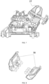
FIG. 10 is a schematic view showing the mounting relationship between a battery pack coupling portion of a fan and a battery pack of the fan according to the present application; -
FIG. 11 is a structural view showing a usage scenario of a power tool according to the present application; -
FIG. 12 is a structural view showing another usage scenario of a power tool according to the present application; -
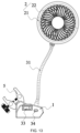
FIG. 13 is a structural view of a fan according to an example of the present application at a first viewing angle; -
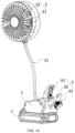
FIG. 14 is a structural view of a fan according to an example of the present application at a second viewing angle; -
FIG. 15 is a structural view of a battery pack according to an example of the present application; -
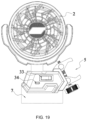
FIG. 16 is a structural view of a coupling portion and a battery pack according to an example of the present application; -
FIG. 17 is a structural view of a fan according to an example of the present application at a third viewing angle; -
FIG. 18 is a structural view of a fan according to an example of the present application at a fourth viewing angle; -
FIG. 19 is a structural view of another fan according to an example of the present application at a first viewing angle; and -
FIG. 20 is a structural view of another fan according to an example of the present application at a second viewing angle. - Before any examples of this application are explained in detail, it is to be understood that this application is not limited to its application to the structural details and the arrangement of components set forth in the following description or illustrated in the above drawings.
- In this application, the terms "comprising", "including", "having" or any other variation thereof are intended to cover an inclusive inclusion such that a process, method, article or device comprising a series of elements includes not only those series of elements, but also other elements not expressly listed, or elements inherent in the process, method, article, or device. Without further limitations, an element defined by the phrase "comprising a ..." does not preclude the presence of additional identical elements in the process, method, article, or device comprising that element.
- In this application, the term "and/or" is a kind of association relationship describing the relationship between associated objects, which means that there can be three kinds of relationships. For example, A and/or B can indicate that A exists alone, A and B exist simultaneously, and B exists alone. In addition, the character "/" in this application generally indicates that the contextual associated objects belong to an "and/or" relationship.
- In this application, the terms "connection", "combination", "coupling" and "installation" may be direct connection, combination, coupling or installation, and may also be indirect connection, combination, coupling or installation. Among them, for example, direct connection means that two members or assemblies are connected together without intermediaries, and indirect connection means that two members or assemblies are respectively connected with at least one intermediate members and the two members or assemblies are connected by the at least one intermediate members. In addition, "connection" and "coupling" are not limited to physical or mechanical connections or couplings, and may include electrical connections or couplings.
- In this application, it is to be understood by those skilled in the art that a relative term (such as "about", "approximately", and "substantially") used in conjunction with quantity or condition includes a stated value and has a meaning dictated by the context. For example, the relative term includes at least a degree of error associated with the measurement of a particular value, a tolerance caused by manufacturing, assembly, and use associated with the particular value, and the like. Such relative term should also be considered as disclosing the range defined by the absolute values of the two endpoints. The relative term may refer to plus or minus of a certain percentage (such as 1%, 5%, 10%, or more) of an indicated value. A value that did not use the relative term should also be disclosed as a particular value with a tolerance. In addition, "substantially" when expressing a relative angular position relationship (for example, substantially parallel, substantially perpendicular), may refer to adding or subtracting a certain degree (such as 1 degree, 5 degrees, 10 degrees or more) to the indicated angle.
- In this application, those skilled in the art will understand that a function performed by an assembly may be performed by one assembly, multiple assemblies, one member, or multiple members. Likewise, a function performed by a member may be performed by one member, an assembly, or a combination of members.
- In this application, the terms "up", "down", "left", "right", "front", and "rear"" and other directional words are described based on the orientation or positional relationship shown in the drawings, and should not be understood as limitations to the examples of this application. In addition, in this context, it also needs to be understood that when it is mentioned that an element is connected "above" or "under" another element, it can not only be directly connected "above" or "under" the other element, but can also be indirectly connected "above" or "under" the other element through an intermediate element. It should also be understood that orientation words such as upper side, lower side, left side, right side, front side, and rear side do not only represent perfect orientations, but can also be understood as lateral orientations. For example, lower side may include directly below, bottom left, bottom right, front bottom, and rear bottom.
- A fan is provided in this example. The fan is applicable in fields such as daily life and industrial production. As shown in
FIGS. 1 and2 , the fan includes asupport base 1, afan assembly 2, and a drive assembly. Thesupport base 1 has a placement plane to be supported on an external structure (such as a tabletop or the ground). Thefan assembly 2 includes asupport body 21, a rotating shaft, andfan blades 22. Thesupport base 1 has a grille-shaped structure. The rotating shaft is rotatably disposed in thesupport base 1. Thefan blades 22 are connected to the rotating shaft and enclosed in thesupport base 1. The drive assembly is used for driving the rotating shaft and thefan blades 22 to synchronously rotate about arotation axis 201. In this example, thesupport base 1 has a circular outline. In another example, the outline of thesupport base 1 may be square, elliptical, or in another special shape. The shape of the outline of thesupport base 1 is not specifically limited here. - In some examples, as shown in
FIG. 1 , the fan further includes afirst pivot structure 3. One end of thefirst pivot structure 3 is connected to thesupport base 1, and the other end of thefirst pivot structure 3 is connected to thefan assembly 2. Thefirst pivot structure 3 supports thefan assembly 2. Thefirst pivot structure 3 can rotate 360° about afirst pivot axis 202. Thus, the direction of thefirst pivot structure 3 may be adjusted through the rotation so that the orientation of thefan assembly 2 is flexibly adjusted, thereby adjusting the direction of wind from the fan. Optionally, thefirst pivot structure 3 includes a fixed portion and a rotating portion. The fixed portion is fixed to thesupport base 1, and the rotating portion is fixed to thefan assembly 2. The rotating portion is rotatable about thefirst pivot axis 202 relative to the fixed portion. Thus, thefan assembly 2 rotates to change its direction relative to thesupport base 1. - As shown in
FIG. 1 , thefan assembly 2 further includes asecond pivot structure 4. One end of thesecond pivot structure 4 is connected to thefirst pivot structure 3 and is specifically connected to the rotating portion. The other end of thesecond pivot structure 4 is pivotally connected to thesupport base 1. In this structure, thesupport base 1 can rotate 360° about asecond pivot axis 203 relative to thesecond pivot structure 4, thereby further improving the flexibility with which the orientation of thefan assembly 2 is adjusted. Thus, it is convenient to adjust the direction of the fan and it is highly flexible to adjust the direction of the wind, thereby improving user experience. Optionally, thesecond pivot structure 4 includes pivot shafts and asupport arm 41. Thesupport arm 41 may have a semi-circular or U-shaped structure. A first hole and a second hole are provided on two opposite sides of thesupport arm 51 one to one. The pivot shafts and thesupport base 1 are fixedly connected to each other or integrally formed. An end of one of the pivot shafts and an end of the other one of the pivot shafts rotatably mate with the first hole and the second hole, respectively. In this manner, thesupport base 1 is rotatable about thesecond pivot axis 203. In an example, the extension line of each of the pivot shafts is collinear with the diameter of thesupport base 1, that is, thesecond pivot axis 203. Thus, thesupport base 1 can be caused to rotate more smoothly. - In some usage scenarios, no appropriate support surface can be found to support the
support base 1 of the fan. In an example, as shown inFIG. 2 , a clampingassembly 5 is disposed on thesupport base 1. The clampingassembly 5 is used for clamping thesupport base 1 to an external fixedcomponent 100, thereby improving flexibility in the use of the fan. In this example, as shown inFIGS. 3 and 4 , the clampingassembly 5 includes afirst jaw 51, asecond jaw 52, and anadjustment member 53. Thefirst jaw 51 is closer to outer edges of thefan blades 22 than thesecond jaw 52. Theadjustment member 53 passes through thefirst jaw 51 and thesecond jaw 52. Theoperation member 533 connected to theadjustment member 53 is operated to be capable of causing an opening distance between thefirst jaw 51 and thesecond jaw 52 to increase or decrease. The maximum opening distance L formed between thefirst jaw 51 and thesecond jaw 52 is greater than or equal to 35 mm. - The opening distance refers to the distance between the distal-most end of a region that is on the
first jaw 51 and can perform clamping and the distal-most end of a region that is on thesecond jaw 52 and can perform clamping. The larger the opening distance, the more the places that can be clamped. The maximum closing or opening distance of the fan provided in this example can be 50 mm, 55 mm, or 60 mm. Compared with a fan in the existing art, the fan in this example is applicable to multiple working conditions, can be stably clamped at various places that are difficult to clamp, and has a wider range of application. - In this example, as shown in
FIG. 1 , thefirst pivot axis 202 does not pass through the clampingassembly 5, that is, the clampingassembly 5 is completely on the same side of thefirst pivot axis 202. In this structure, the distance H between thesupport base 1 and the uppermost end of the clamping assembly may be designed to be very small. In this example, H is less than or equal to 10 cm. Further, in this example, H is less than or equal to 9 cm. The distance H is small so that the overall height of the whole apparatus can be reduced. Therefore, a compact structure is applicable to more places. - As shown in
FIG. 5 , a first threadedportion 531 and a second threadedportion 532 are spaced on theadjustment member 53. The handedness of the first threadedportion 531 is different from the handedness of the second threadedportion 532. Thesecond jaw 52 is connected to the second threadedportion 532. The second threadedportion 532 can cause thesecond jaw 52 to move. With the threads with two types of handedness, thefirst jaw 51 and thesecond jaw 52 can be quickly opened and closed, thereby saving time spent in adjusting the clampingassembly 5. The length of the first threadedportion 531 along the axial direction of theadjustment member 53 is a first length L1, and the length of the second threadedportion 532 along the axial direction of theadjustment member 53 is a second length L2. The first length L1 may be the same as or different from the second length L2. In an example, the second length L2 is greater than the first length L1, and the difference between the second length L2 and the first length L1 is greater than or equal to 5 mm. Thus, thesecond jaw 52 connected to the second threadedportion 532 can have a large movement range, thereby implementing a larger opening distance. - In an example, the first length L1 is about 15 mm, and the second length L2 is about 22 mm. In an example, the first threaded
portion 531 has 8 threads, and the second threadedportion 532 has 11 threads. In an example, each of the first threadedportion 531 and the second threadedportion 532 has a pitch of about 2 mm. The pitch is adjusted so that the opening or closing speed of the clampingassembly 5 is adjusted. The preceding specific parameters of the first threadedportion 531 and the second threadedportion 532 may be designed according to actual situations. - Based on the preceding structure, with continued reference to
FIGS. 3 and 4 , the clampingassembly 5 further includes a connectingrod 54 and a torsion spring (not shown in the figure). The connectingrod 54 is connected to thesupport base 1. Thefirst jaw 51 is fixedly connected to the connectingrod 54 and is on one side of the connectingrod 54, and thesecond jaw 52 is connected to the connectingrod 54 and is on the other side of the connectingrod 54. Thesecond jaw 52 and thefirst jaw 51 are disposed opposite to each other. The torsion spring is sleeved on the connectingrod 54, and two ends of the spring torsion are connected to thefirst jaw 51 and thesecond jaw 52, respectively. The torsion spring causes thefirst jaw 51 and thesecond jaw 52 to be in an open state. - In the preceding structure, the
second jaw 52 is rotatably connected to thefirst jaw 51 through the connectingrod 54. Theadjustment member 53 passes through thefirst jaw 51 and thesecond jaw 52. Theadjustment member 53 is operated to be capable of causing the opening distance between thefirst jaw 51 and thesecond jaw 52 to increase or decrease. Compared with the manner that asecond jaw 52 can only be translated relative to afirst jaw 51 in the existing art, thefirst jaw 51 and thesecond jaw 52 are opened or closed more quickly and are quicker and more convenient to operate in the preceding solution of this example. - In this example, a clamping range of the clamping
assembly 5 may be characterized by an opening or closing angle. As shown inFIG. 6 , the included angle between connecting lines from the center of the connectingrod 54 to an edge of thefirst jaw 51 and an edge of thesecond jaw 52 respectively is a second included angle β, that is, the opening or closing angle, where 0° ≤ β ≤ 90°. In an example, the second included angle β is about 55°. The maximum opening or closing angle of the clampingassembly 5 can be 90°, and the clampingassembly 5 is applicable to a wide range of working conditions. - As shown in
FIGS. 3 and 4 , the clampingassembly 5 further includes afirst pin 55 and asecond pin 56. Thefirst pin 55 is inserted through thefirst jaw 51, and thesecond pin 56 is inserted through thesecond jaw 52. The first threadedportion 531 is rotatably connected to thefirst pin 55, and the second threadedportion 532 is rotatably connected to thesecond pin 56. Optionally, the first threadedportion 531 rotatably mates with thefirst pin 55 through a bearing, and the second threadedportion 532 is inserted through thesecond pin 56 and threadedly mates with thesecond pin 56. When theadjustment member 53 is rotated, thesecond jaw 52 can be caused to approach or move away from thefirst jaw 51, thereby clamping or releasing an external fixed structure. Of course, the preceding structure is only one possible example of the clampingassembly 5. In another example, the structure of the clampingassembly 5 is not limited. Any structure that can implement a clamping function is applicable in this example. Thefirst jaw 51 has a fixed position and thesecond jaw 52 approaches or moves away from thefirst jaw 51 so that the opening distance between thefirst jaw 51 and thesecond jaw 52 decreases or increases. - As shown in
FIG. 1 , the included angle between the connecting line from the center of thefirst pin 55 to the edge of thefirst jaw 51 and the plane where the fan is placed is a first included angle α, where α > 30°. The larger the angle is, the more scenarios the fan is applicable to. - Further, as shown in
FIG. 7 , anelastic pad 57 is disposed on each of thefirst jaw 51 and thesecond jaw 52 and is in direct contact with the external fixedcomponent 100. Theelastic pad 57 is disposed so that the friction force between the jaw and the external fixedcomponent 100 can be increased, thereby improving clamping stability. In addition, the jaw can be prevented from damaging the external fixedcomponent 100. Optionally, as shown inFIG. 8 , each of thefirst jaw 51 and thesecond jaw 52 is provided with a mountingslot 58 for mounting theelastic pad 57. Theelastic pad 57 may be a rubber pad, a silica gel pad, or a soft pad that has elasticity and is made of another material. - Referring to
FIG. 9 , each of thefirst jaw 51 and/or thesecond jaw 52 includes afirst clamping surface 511 and asecond clamping surface 512. The included angle between thefirst clamping surface 511 and thesecond clamping surface 512 is a third included angle γ, where 100° ≤ γ ≤ 150°. The angle range can cause the jaws to have greater clamping forces and greater clamping stability. Thus, the jaws are applicable to scenarios where the clamping is not easily performed. In an example, the third included angle γ is greater than or equal to 100 degrees and less than or equal to 150 degrees. In another example, the third included angle γ is greater than or equal to 110 degrees and less than or equal to 140 degrees. In another example, the third included angle γ is greater than or equal to 120 degrees and less than or equal to 140 degrees. Only several ranges are listed here. The third included angle γ may be selected according to a specific working condition in actual design. - As shown in
FIGS. 1 and10 , the fan further includes a batterypack coupling portion 6 and abattery pack 7. The batterypack coupling portion 6 is located at an end of the fan adjacent to thesupport base 1. The batterypack coupling portion 6 is formed on thesupport base 1. In this example, the batterypack coupling portion 6 is configured on thesupport base 1, and thebattery pack 7 is detachably mounted on the batterypack coupling portion 6. After thebattery pack 7 is mounted on the batterypack coupling portion 6, thebattery pack 7 can power the drive assembly. Specifically, thebattery pack 7 may be a rechargeable battery used by the power tool. In some examples, the nominal voltage of thebattery pack 7 is greater than or equal to 12 V and less than or equal to 24 V. In some examples, the nominal voltage of thebattery pack 7 is 12 V. In some examples, the nominal voltage of thebattery pack 7 is 20 V. The batterypack coupling portion 6 and thebattery pack 7 are disposed so that the fan can be used normally without being connected to an external power supply. Moreover, when the power of thebattery pack 7 runs out, thebattery pack 7 can be replaced by anew battery pack 7. Thus, the fan can be used continuously, further improving the flexibility in the use of the fan. In this example, the batterypack coupling portion 6 includes several contacts. The contacts are electrically connected to the drive assembly. Correspondingly, thebattery pack 7 includes several terminals. After thebattery pack 7 is mechanically connected to the batterypack coupling portion 6, the terminals are electrically connected to the contacts just correspondingly so that the drive assembly can be powered. Optionally, thebattery pack 7 may be detachably connected to the batterypack coupling portion 6 in the manner of insertion, threaded connection, or the like, which is not limited here. - In this example, the drive assembly includes an electric motor. The output end of the electric motor is connected to the rotating shaft of the
fan assembly 2 to drive thefan blades 22 to rotate. Further, the electric motor may be a speed regulation motor so that the rotational speed of thefan blades 22 is adjustable. In another example, the electric motor may be an ordinary electric motor. However, the fan is further equipped with a governor. The governor and the electric motor cooperate with each other so that the rotational speed of the fan is adjustable. - In this example, the drive assembly is disposed in the
support base 1 and used for driving thefan blades 22 of thefan assembly 2 to rotate. - A power tool is provided in this example. The power tool includes an
output assembly 300, a battery pack coupling portion, and a clamping assembly. Theoutput assembly 300 is used for performing output work. The battery pack coupling portion is used for mounting a battery pack powering theoutput assembly 300. The clamping assembly is configured to clamp the power tool to an external fixed component. Only parts different from example one are specifically described below. Parts in example two that are the same as those in example one are not described again. - The clamping
assembly 5 includes afirst jaw 51, asecond jaw 52, and anadjustment member 53. Thefirst jaw 51 is closer to theoutput assembly 300 than thesecond jaw 52. Theadjustment member 53 passes through thefirst jaw 51 and thesecond jaw 52. Theadjustment member 53 is operated to be capable of causing an opening distance between thefirst jaw 51 and thesecond jaw 52 to increase or decrease. Thus, the release or clamping of the clampingassembly 5 is implemented. The maximum opening distance formed between thefirst jaw 51 and thesecond jaw 52 is greater than or equal to 35 mm. The opening distance refers to the distance between the distal-most end of a region that is on thefirst jaw 51 and can perform clamping and the distal-most end of a region that is on thesecond jaw 52 and can perform clamping. The larger the opening distance, the more the places that can be clamped. The maximum closing or opening distance of the power tool provided in this example can be 50 mm, 55 mm, or 60 mm. Compared with a power tool in the existing art, the power tool in this example is applicable to multiple working conditions, can be stably clamped at various places that are difficult to clamp, and has a wider range of application. -
FIGS. 11 and12 show two mounting manners of the fan inFIGS. 1 to 10 .FIG. 11 shows a usage scenario of the power tool provided in this example. The external fixedcomponent 100 has a rod-shaped structure. Due to a space limitation, the power tool can only be inverted and suspended during use. The power tool can be stably clamped to the external fixedcomponent 100 to be used with high security and stability. -
FIG. 12 shows another usage scenario of the power tool provided in this example. The external fixedcomponent 100 has a structure in the shape of a thick plate. Generally, it is difficult to clamp a power tool to the external fixedcomponent 100. The power tool can be stably clamped to the external fixedcomponent 100 to be used with high security and stability. - It is to be noted that in addition to the preceding fan, the clamping
assembly 5 involved in the present application is also applicable to other types of power tools. In an example, an audio device may also use the clampingassembly 5 involved in the present application. In an example, a lamp may also use the clampingassembly 5 involved in the present application. In an example, a test device may also use the clampingassembly 5 involved in the present application. That is to say, a specific output manner of theoutput assembly 300 is changed so that a specific work type of the power tool can be changed. - The power tool in the example is specifically a pole power tool, which is specifically a string trimmer. It is to be understood that the power tool may be a handheld power tool, for example, a drill, a pruner, or a sander. Alternatively, the power tool may be a table tool, for example, a table saw or a miter saw. Alternatively, the power tool may be a hand-push power tool, for example, a hand-push mower or a hand-push snow thrower. Alternatively, the power tool may be a riding power tool, for example, a riding mower, a riding vehicle, or an all-terrain vehicle. Alternatively, the power tool may be a robotic tool, for example, a robotic mower or a robotic snow thrower.
- In some examples, the power tool may be an electric drill, an electric lamp, an electric vehicle, or the like. In some examples, the power tool may be an engine power tool, for example, an engine string trimmer or an engine mower.
- In some examples, the power tool may be a garden tool, for example, a pruner, a blower, a mower, or a chain saw. Alternatively, the power tool may be a decoration tool, for example, a screwdriver, a nail gun, a circular saw, or a sander.
- In some examples, the power tool may be a vegetation maintenance tool, for example, a string trimmer, a mower, a pruner, or a chain saw. Alternatively, the power tool may be a cleaning tool, for example, a blower, a snow thrower, or a washer. Alternatively, the power tool may be a drilling tool, for example, a drill, a screwdriver, a wrench, or an electric hammer. Alternatively, the power tool may be a sawing tool, for example, a reciprocating saw, a jigsaw, or a circular saw. Alternatively, the power tool may be a table tool, for example, a table caw a miter caw a metal cutter, or an electric router. Alternatively, the power tool may be a sanding tool, for example, an angle grinder or a sander. Alternatively, the power tool may be a non-motorized electrical device, for example, a lamp, an audio device, or a test device.
- It is to be understood that any power device with a motor or an electric motor may adopt the technical solution disclosed in this example. Any power device adopting the technical solution disclosed in this example falls within the scope of the present application. For example, the power device may be a power head. The power head includes a motor or an electric motor and is configured to be adapted to some
output assemblies 300 to implement the function of the tool. -
FIGS. 13 to 20 disclose examples of the clampingassembly 5 in other fans. - In some examples, as shown in
FIG. 13 , a fan further includes aflexible shaft assembly 31. One end of theflexible shaft assembly 31 is connected to asupport base 1, and the other end of theflexible shaft assembly 31 is connected to afan assembly 2. Theflexible shaft assembly 31 supports thefan assembly 2. The extension direction of theflexible shaft assembly 31 is adjustable. Therefore, the extension direction of theflexible shaft assembly 31 is adjusted through a twist so that the orientation of thefan assembly 2 can be flexibly adjusted, thereby adjusting the direction of wind from the fan. Thefan assembly 2 can be adjusted through theflexible shaft assembly 31 in a left and right direction, an up and down direction, and a front and rear direction simultaneously. Thus, it is convenient to adjust the direction of the fan and it is highly flexible to adjust the direction of the wind, thereby improving user experience. Optionally, the total length of theflexible shaft assembly 31 may be selected and set according to actual requirements and is not limited here. - In some examples, as shown in
FIG. 13 , the fan in this example further includes a Type-C interface 34 electrically connected to a drive assembly. Further, the fan in this example further includes a power cord (not shown). One end of the power cord can be inserted into the Type-C interface 34, and the other end of the power cord is configured to be inserted into an external power supply (such as a socket or wall jacks), thereby powering the drive assembly. On the one hand, the Type-C interface 34 is disposed so that the power cord of the fan can be independently disposed. Before the fan is moved, the power cord may be detached. Thus, the power cord will not be dragged and damaged. On the other hand, in the existing art, many electrical devices have power cords whose output terminals are matched with the Type-C interface 34. Thus, the fan can share the power cord with other electrical devices, and it is more convenient for the user to use the fan. In this example, one end of the power cord to be inserted into the external power supply includes one or more of a two-pin plug, a three-pin plug, and a USB plug, which is not specifically limited here. - In this example, as shown in
FIG. 13 , the Type-C interface 34 is disposed on asupport body 21 so that the risk can be reduced that theflexible shaft assembly 31 is wound with the power cord when being adjusted. - As shown in
FIG. 13 , the fan further includes aswitch 33. Theswitch 33 is electrically connected to the drive assembly and is configured to causefan blades 22 to start or stop rotating. Theswitch 33 is disposed so that it is more convenient to use the fan. Optionally, theswitch 33 may be a simple ON/OFF switch or a switch with a speed regulation function, which is not limited here. Further, in this example, theswitch 33 is disposed on thesupport base 1, and in other examples, theswitch 33 may be disposed on thesupport base 1 of thefan assembly 2, which is not specifically limited here. - As shown in
FIGS. 14 to 16 , the fan further includes a batterypack coupling portion 6 and abattery pack 7. The batterypack coupling portion 6 is located at an end of the fan adjacent to the support base. In this example, the batterypack coupling portion 6 is configured on thesupport base 1, and thebattery pack 7 is detachably mounted on the batterypack coupling portion 6. After thebattery pack 7 is mounted on the batterypack coupling portion 6, thebattery pack 7 can power the drive assembly. Specifically, thebattery pack 7 may be a rechargeable battery used by a power tool. In some examples, the nominal voltage of thebattery pack 7 is greater than or equal to 12 V and less than or equal to 24 V. In some examples, the nominal voltage of thebattery pack 7 is 12 V. In some examples, the nominal voltage of thebattery pack 7 is 20 V. The batterypack coupling portion 6 and thebattery pack 7 are disposed so that the fan can be used normally without being connected to the external power supply. Moreover, when the power of thebattery pack 7 runs out, thebattery pack 7 can be replaced by anew battery pack 7. Thus, the fan can be used continuously, further improving flexibility in the use of the fan. In this example, the batterypack coupling portion 6 includesseveral contacts 61. Thecontacts 61 are electrically connected to the drive assembly. Correspondingly, thebattery pack 7 includesseveral terminals 71. After thebattery pack 7 is mechanically connected to the batterypack coupling portion 6, theterminals 71 are electrically connected to thecontacts 61 just correspondingly so that the drive assembly can be powered. Optionally, thebattery pack 7 may be detachably connected to the batterypack coupling portion 6 in the manner of insertion, threaded connection, or the like, which is not limited here. - In this example, the drive assembly includes an electric motor. The output end of the electric motor is connected to the rotating shaft of the
fan assembly 2 to drive thefan blades 22 to rotate. Further, the electric motor may be a speed regulation motor so that the rotational speed of thefan blades 22 is adjustable. In another example, the electric motor may be an ordinary electric motor. However, the fan is further equipped with a governor. The governor and the electric motor cooperate with each other so that the rotational speed of the fan is adjustable. - Optionally, in some examples, the fan includes a nozzle and a water storage tank (not shown), so the fan can implement a spray function.
- Optionally, in some examples, the drive assembly is connected to the
support base 1 of thefan assembly 2. In this configuration manner, it is convenient for the drive assembly to drivingly mate with thefan blades 22. - In this example, the drive assembly is disposed in the
support base 1. Theflexible shaft assembly 31 includes a flexible drive shaft and a sheath that is sleeved on the outside of the flexible drive shaft and can be bent. One end of the sheath is connected to thesupport base 1, and the other end of the sheath is connected to thesupport base 1 of thefan assembly 2. One end of the flexible drive shaft is rotatably supported on thesupport base 1 and is drivingly connected to the drive assembly, and the other end of the flexible drive shaft is rotatably supported on thesupport base 1 and drivingly mates with thefan blades 22. On the one hand, the flexible drive shaft cooperates with the sheath to support thefan assembly 2, reducing the vibration of the fan during work. Thus, stability is improved. On the other hand, the flexible drive shaft implements the power transmission between the drive assembly and thefan blades 22. - In this example, the one end of the flexible drive shaft is rotatably supported on the
support base 1 through a bearing and is connected to the output shaft of the electric motor, and the other end of the flexible drive shaft is rotatably supported on thesupport base 1 of thefan assembly 2 through a bearing and is connected to the rotating shaft of thefan assembly 2. When the electric motor outputs rotational movement, the flexible drive shaft drives the rotating shaft to rotate together, thereby implementing the rotation of thefan blades 22. It is to be noted that the flexible drive shaft that is adjustable in the extension direction and can implement the rotation and the transmission specifically belongs to the existing art. The details are not repeated here. Further, two ends of the sheath may be connected to thesupport base 1 and thesupport base 1 through threaded connection, engagement, or the like, respectively. Those skilled in the art may select and configure a connection manner according to actual requirements, which is not limited here. - In some usage scenarios, no appropriate support surface can be found to support the
support base 1 of the fan. In an example, as shown inFIG. 14 , the clampingassembly 5 is disposed on thesupport base 1. The clampingassembly 5 is used for clamping thesupport base 1 to an external fixed component, thereby improving the flexibility in the use of the fan. In this example, as shown inFIG. 14 , the clampingassembly 5 includes afirst jaw 51, asecond jaw 52, a jaw shaft, a torsion spring, and anadjustment member 53. The jaw shaft is connected to thesupport base 1. Thefirst jaw 51 is fixedly connected to thesupport base 1 and is located on a side of the jaw shaft. Thesecond jaw 52 is disposed opposite to thefirst jaw 51 and is located on the other side of the jaw shaft. Two ends of the torsion spring that are sleeved on the jaw shaft are connected to thefirst jaw 51 and thesecond jaw 52, respectively. The torsion spring causes thefirst jaw 51 and thesecond jaw 52 to be in an open state. One end of theadjustment member 53 rotatably mates with thefirst jaw 51 through a bearing, and the other end of theadjustment member 53 is inserted through thesecond jaw 52 and threadedly mates with thesecond jaw 52. When theadjustment member 53 is rotated, thesecond jaw 52 can be caused to approach thefirst jaw 51, thereby clamping an external fixed structure. Of course, the preceding structure is only one possible example of the clampingassembly 5. In another example, the structure of the clampingassembly 5 is not limited. Any structure that can implement a clamping function is applicable in this example. - In this example, as shown in
FIGS. 17 and18 , at least onehook 32 is disposed on thesupport base 1 and is used for hooking thesupport base 1 to the external fixed component. Thus, the flexibility of positions where the fan can be placed is further improved. Optionally, one, two, ormore hooks 32 may be provided, and the number ofhooks 32 is not specifically limited here. Further, the at least onehook 32 may be disposed on one or more sidewalls of thesupport base 1, which is flexibly adjusted according to actual requirements. Optionally, the at least onehook 32 may be integrally formed with thesupport base 1 through injection molding or may be connected to thesupport base 1 through a fastener. - In some examples, as shown in
FIGS. 19 and20 , the fan includes asupport base 1, afan assembly 2, and a drive assembly. Thefan assembly 2 includes asupport body 21 andfan blades 22. Thesupport base 1 of thefan assembly 2 is directly connected to thesupport base 1. The drive assembly is disposed in thesupport base 1 and used for driving thefan blades 22 of thefan assembly 2 to rotate. In this example, the fan includes a clampingassembly 5 connected to thesupport base 1 and hooks 32 connected to thesupport base 1. The fan also includes aswitch 33 for turning on or off the drive assembly. The fan also includes a Type-C interface 34 electrically connected to the drive assembly. Specific functions and technical effects of the clampingassembly 5, thehooks 32, theswitch 33, and the Type-C interface 34 are the same as those described above. The details are not repeated here. - The basic principles, main features, and advantages of this application are shown and described above. It is to be understood by those skilled in the art that the aforementioned examples do not limit the present application in any form, and all technical solutions obtained through equivalent substitutions or equivalent transformations fall within the scope of the present application.
Claims (15)
- A fan, comprising:a support base (1);a fan assembly (2) comprising fan blades(22); anda battery pack coupling portion (6) used for mounting a battery pack (7) powering the fan assembly;wherein the fan further comprises:a clamping assembly (5) disposed on the support base and configured to clamp the support base to an external fixed component;wherein the clamping assembly comprises a first jaw (51), a second jaw (52), and an adjustment member (53), wherein the first jaw is closer to the fan blades than the second jaw, the adjustment member passes through the first jaw and the second jaw, the adjustment member is operated to be capable of increasing or decreasing an opening distance between the first jaw and the second jaw, and a maximum opening distance (L) formed between the first jaw and the second jaw is greater than or equal to 35 mm.
- The fan according to claim 1, wherein a first threaded portion (531) and a second threaded portion (532) are spaced on the adjustment member, wherein the second jaw is connected to the second threaded portion, the second threaded portion permitting the second jaw to move along.
- The fan according to claim 2, wherein a length of the first threaded portion along an axial direction of the adjustment member is a first length (L1), and a length of the second threaded portion along the axial direction of the adjustment member is a second length (L2), and the second length is greater than the first length, and a difference between the second length and the first length is greater than or equal to 5 mm.
- The fan according to claim 2, wherein the clamping assembly further comprises a first pin (55) and a second pin (56), wherein the first pin is inserted through the first jaw, the second pin is inserted through the second jaw, the first threaded portion is rotatably connected to the first pin, and the second threaded portion is rotatably connected to the second pin.
- The fan according to claim 4, wherein an included angle between a connecting line from a center of the first pin to an edge of the first jaw and a plane where the fan is placed is a first included angle α, wherein α > 30°.
- The fan according to claim 2, wherein the clamping assembly further comprises a connecting rod (54) connected to the support base, wherein the first jaw is connected to the connecting rod and is on one side of the connecting rod, and the second jaw is connected to the connecting rod and is on another side of the connecting rod.
- The fan according to claim 6, wherein an included angle between connecting lines from a center of the connecting rod to an edge of the first jaw and an edge of the second jaw respectively is a second included angle β, wherein 0° ≤ β ≤ 90°.
- The fan according to any one of claims 1 to 7, wherein an elastic pad (57) is disposed on each of the first jaw and the second jaw and is in direct contact with the external fixed component.
- The fan according to any one of claims 1 to 7, wherein each of the first jaw and/or the second jaw comprises a first clamping surface (511) and a second clamping surface (512), and an included angle between the first clamping surface and the second clamping surface is a third included angle γ, wherein 100° ≤ γ ≤ 150°.
- The fan according to any one of claims 1 to 7, wherein the battery pack is mounted below the clamping assembly.
- The fan according to claim 1, wherein a distance H between the support base and an uppermost end of the clamping assembly is less than or equal to 10 cm.
- The fan according to claim 1, wherein a distance H between the support base and an uppermost end of the clamping assembly is less than or equal to 9 cm.
- The fan according to claim 1, further comprising a drive assembly and a Type-C interface (34), wherein the drive assembly is used for driving the fan blades to rotate, the Type-C interface is electrically connected to the drive assembly, and the Type-C interface is configured such that a power cord is capable of being plugged into the Type-C interface to power the drive assembly.
- The fan according to claim 1, further comprising a flexible shaft assembly (31), wherein one end of the flexible shaft assembly is connected to the support base, another end of the flexible shaft assembly is connected to the fan assembly, and an extension direction of the flexible shaft assembly is adjustable.
- The fan according to claim 13, further comprising a switch (33) electrically connected to the drive assembly and configured to cause the fan blades to start or stop rotating.
Applications Claiming Priority (1)
| Application Number | Priority Date | Filing Date | Title |
|---|---|---|---|
| CN202322029980.5U CN220204166U (en) | 2023-07-28 | 2023-07-28 | Fan and electric tool |
Publications (1)
| Publication Number | Publication Date |
|---|---|
| EP4497951A1 true EP4497951A1 (en) | 2025-01-29 |
Family
ID=89154058
Family Applications (1)
| Application Number | Title | Priority Date | Filing Date |
|---|---|---|---|
| EP24176835.7A Withdrawn EP4497951A1 (en) | 2023-07-28 | 2024-05-20 | Fan with a clamping assembly |
Country Status (3)
| Country | Link |
|---|---|
| US (1) | US20250035260A1 (en) |
| EP (1) | EP4497951A1 (en) |
| CN (1) | CN220204166U (en) |
Citations (3)
| Publication number | Priority date | Publication date | Assignee | Title |
|---|---|---|---|---|
| DE9417353U1 (en) * | 1994-10-28 | 1995-01-26 | Ludwig Hunger Maschinenfabrik GmbH, 86916 Kaufering | Clamping device |
| CN217898227U (en) * | 2022-07-12 | 2022-11-25 | 南京泉峰科技有限公司 | Fan with fan body |
| US11629732B1 (en) * | 2022-08-08 | 2023-04-18 | Guangdong Aoyun Technology Co., Ltd. | Fan with easy-to-assemble clamping device |
-
2023
- 2023-07-28 CN CN202322029980.5U patent/CN220204166U/en active Active
-
2024
- 2024-05-20 EP EP24176835.7A patent/EP4497951A1/en not_active Withdrawn
- 2024-05-21 US US18/670,430 patent/US20250035260A1/en active Pending
Patent Citations (3)
| Publication number | Priority date | Publication date | Assignee | Title |
|---|---|---|---|---|
| DE9417353U1 (en) * | 1994-10-28 | 1995-01-26 | Ludwig Hunger Maschinenfabrik GmbH, 86916 Kaufering | Clamping device |
| CN217898227U (en) * | 2022-07-12 | 2022-11-25 | 南京泉峰科技有限公司 | Fan with fan body |
| US11629732B1 (en) * | 2022-08-08 | 2023-04-18 | Guangdong Aoyun Technology Co., Ltd. | Fan with easy-to-assemble clamping device |
Non-Patent Citations (1)
| Title |
|---|
| NEEWER: "Home NEEWER ST83 Super Clamp with 3" Dual Ballhead Magic Arm", 12 May 2023 (2023-05-12), XP093214665, Retrieved from the Internet <URL:https://neewer.com/products/neewer-st83-super-clamp-with-3-dual-ballhead-magic-arm-66602879?_pos=10&_sid=d43e05d0e&_ss=r> [retrieved on 20241014] * |
Also Published As
| Publication number | Publication date |
|---|---|
| US20250035260A1 (en) | 2025-01-30 |
| CN220204166U (en) | 2023-12-19 |
Similar Documents
| Publication | Publication Date | Title |
|---|---|---|
| US20140068952A1 (en) | Dual oscillating multi-tool saw | |
| US20150078811A1 (en) | Modular power tool | |
| CN212653398U (en) | Long rod type electric tool | |
| US8651922B2 (en) | Inline handheld power tool | |
| GB2426391A (en) | Securing a battery to a battery charger | |
| CN101553346A (en) | Handheld Power Tools | |
| CN106134617A (en) | Grass-mowing machine | |
| WO2022242728A1 (en) | Power device and electric tool | |
| US20050115081A1 (en) | Electric cutter | |
| US20250035260A1 (en) | Fan and power tool | |
| CN207858762U (en) | A kind of detachable multifunctional electric combined tool | |
| US20090088052A1 (en) | Inline handheld power tool | |
| US8708619B2 (en) | Power tool with integral pencil sharpener | |
| CN113366988A (en) | Power device and electric tool | |
| CN217898227U (en) | Fan with fan body | |
| US20160114471A1 (en) | Adapter for multifunctional electric drill | |
| CN113305788B (en) | Long rod type electric tool | |
| CN214758034U (en) | High branch machine | |
| CN108055935B (en) | Blade and pruner | |
| CN212794851U (en) | Long rod power tools | |
| CN212257951U (en) | Electric grounding wire operating rod | |
| CN210389010U (en) | Chain screw wrench | |
| US3851390A (en) | Trimming attachment | |
| CN209822533U (en) | Direct current trigger switch with quick dragging structure | |
| CN212259865U (en) | Novel electric scissors |
Legal Events
| Date | Code | Title | Description |
|---|---|---|---|
| PUAI | Public reference made under article 153(3) epc to a published international application that has entered the european phase |
Free format text: ORIGINAL CODE: 0009012 |
|
| STAA | Information on the status of an ep patent application or granted ep patent |
Free format text: STATUS: THE APPLICATION HAS BEEN PUBLISHED |
|
| AK | Designated contracting states |
Kind code of ref document: A1 Designated state(s): AL AT BE BG CH CY CZ DE DK EE ES FI FR GB GR HR HU IE IS IT LI LT LU LV MC ME MK MT NL NO PL PT RO RS SE SI SK SM TR |
|
| STAA | Information on the status of an ep patent application or granted ep patent |
Free format text: STATUS: THE APPLICATION IS DEEMED TO BE WITHDRAWN |
|
| 18D | Application deemed to be withdrawn |
Effective date: 20250730 |