EP4497662A1 - High-roof structure for truck - Google Patents
High-roof structure for truck Download PDFInfo
- Publication number
- EP4497662A1 EP4497662A1 EP23796244.4A EP23796244A EP4497662A1 EP 4497662 A1 EP4497662 A1 EP 4497662A1 EP 23796244 A EP23796244 A EP 23796244A EP 4497662 A1 EP4497662 A1 EP 4497662A1
- Authority
- EP
- European Patent Office
- Prior art keywords
- side frames
- rear side
- frame
- roof
- fragile portion
- Prior art date
- Legal status (The legal status is an assumption and is not a legal conclusion. Google has not performed a legal analysis and makes no representation as to the accuracy of the status listed.)
- Pending
Links
Images




Classifications
-
- B—PERFORMING OPERATIONS; TRANSPORTING
- B60—VEHICLES IN GENERAL
- B60J—WINDOWS, WINDSCREENS, NON-FIXED ROOFS, DOORS, OR SIMILAR DEVICES FOR VEHICLES; REMOVABLE EXTERNAL PROTECTIVE COVERINGS SPECIALLY ADAPTED FOR VEHICLES
- B60J7/00—Non-fixed roofs; Roofs with movable panels, e.g. rotary sunroofs
- B60J7/08—Non-fixed roofs; Roofs with movable panels, e.g. rotary sunroofs of non-sliding type, i.e. movable or removable roofs or panels, e.g. let-down tops or roofs capable of being easily detached or of assuming a collapsed or inoperative position
- B60J7/16—Non-fixed roofs; Roofs with movable panels, e.g. rotary sunroofs of non-sliding type, i.e. movable or removable roofs or panels, e.g. let-down tops or roofs capable of being easily detached or of assuming a collapsed or inoperative position non-foldable and rigid, e.g. a one-piece hard-top or a single rigid roof panel
- B60J7/1628—Non-fixed roofs; Roofs with movable panels, e.g. rotary sunroofs of non-sliding type, i.e. movable or removable roofs or panels, e.g. let-down tops or roofs capable of being easily detached or of assuming a collapsed or inoperative position non-foldable and rigid, e.g. a one-piece hard-top or a single rigid roof panel for covering the passenger compartment
- B60J7/1635—Non-fixed roofs; Roofs with movable panels, e.g. rotary sunroofs of non-sliding type, i.e. movable or removable roofs or panels, e.g. let-down tops or roofs capable of being easily detached or of assuming a collapsed or inoperative position non-foldable and rigid, e.g. a one-piece hard-top or a single rigid roof panel for covering the passenger compartment of non-convertible vehicles
-
- B—PERFORMING OPERATIONS; TRANSPORTING
- B62—LAND VEHICLES FOR TRAVELLING OTHERWISE THAN ON RAILS
- B62D—MOTOR VEHICLES; TRAILERS
- B62D21/00—Understructures, i.e. chassis frame on which a vehicle body may be mounted
- B62D21/15—Understructures, i.e. chassis frame on which a vehicle body may be mounted having impact absorbing means, e.g. a frame designed to permanently or temporarily change shape or dimension upon impact with another body
-
- B—PERFORMING OPERATIONS; TRANSPORTING
- B62—LAND VEHICLES FOR TRAVELLING OTHERWISE THAN ON RAILS
- B62D—MOTOR VEHICLES; TRAILERS
- B62D25/00—Superstructure or monocoque structure sub-units; Parts or details thereof not otherwise provided for
- B62D25/06—Fixed roofs
-
- B—PERFORMING OPERATIONS; TRANSPORTING
- B62—LAND VEHICLES FOR TRAVELLING OTHERWISE THAN ON RAILS
- B62D—MOTOR VEHICLES; TRAILERS
- B62D33/00—Superstructures for load-carrying vehicles
- B62D33/06—Drivers' cabs
-
- B—PERFORMING OPERATIONS; TRANSPORTING
- B60—VEHICLES IN GENERAL
- B60K—ARRANGEMENT OR MOUNTING OF PROPULSION UNITS OR OF TRANSMISSIONS IN VEHICLES; ARRANGEMENT OR MOUNTING OF PLURAL DIVERSE PRIME-MOVERS IN VEHICLES; AUXILIARY DRIVES FOR VEHICLES; INSTRUMENTATION OR DASHBOARDS FOR VEHICLES; ARRANGEMENTS IN CONNECTION WITH COOLING, AIR INTAKE, GAS EXHAUST OR FUEL SUPPLY OF PROPULSION UNITS IN VEHICLES
- B60K13/00—Arrangement in connection with combustion air intake or gas exhaust of propulsion units
- B60K13/02—Arrangement in connection with combustion air intake or gas exhaust of propulsion units concerning intake
Definitions
- the present disclosure relates to a high roof structure applied to a cab of a truck.
- heavy-duty trucks sometimes adopt a high roof structure which provides a roof panel at a higher position than a normal position to expand a compartment formed in a cab.
- a high roof structure is mounted on a cab body having an open ceiling (see, for example, Patent Literature 1).
- the cab with the high roof structure as described above has a small vehicle height difference from a mounted object such as a cargo box disposed behind, and thus, it is difficult to mount a drag foiler (air deflector) for reducing air resistance during traveling.
- a drag foiler air deflector
- some high roof structures adopt a roof panel that inclines so as to gradually increase the vehicle height from a front side to a rear side.
- the conventional high roof structure has room for improvement in suppressing the deformation of the cab body by securing strength against the load from above.
- the present disclosure has been devised in view of the above-mentioned problems, and an object thereof is to suppress deformation of a cab body against a load from above.
- the present disclosure has been made to solve at least a part of the above problems, and can be realized as the following aspects or application examples.
- the rear side frames erect higher than the front side frames, a load input from above is first input to the rear side frames before being input to the front side frames.
- a compressive load in the vehicle height direction acts on the rear side frames, which causes the fragile portion having a relatively low strength to be crushed first in the vehicle height direction, reducing the height difference between the front side frames and the rear side frames.
- a downward load is input to the front side frames as well as to the rear side frames.
- the load is distributed not only to the rear side frames but also to the front side frames, so that the load is inhibited from concentrating on the rear side frames. Therefore, after the fragile portion is crushed, large deformation of the rear side frames is suppressed.
- both the front side frames and the rear side frames can function as tension rods to act against the load. Therefore, the strength can be secured against the load from above. Hence, the deformation of the cab body can be suppressed.
- the high roof structure according to the present application example may include: a front roof frame that connects respective upper ends of the front side frames to each other; and a rear roof frame that connects respective upper ends of the rear side frames to each other.
- the load input from above can be transmitted to each of the front side frames and the rear side frames through the front roof frame and the rear roof frame.
- the front roof frame and the rear roof frame function as tension rods, the front side frames and the rear side frames can be suppressed from collapsing inward in the vehicle width direction.
- the load when the load is input from above, the load can be more reliably distributed to each of the front side frames and the rear side frames. Therefore, each of the front side frames and the rear side frames can more reliably oppose the load input from above. Thus, the deformation of the cab body can be further suppressed.
- the high roof structure according to the present application example may include: a long roof frame that extends in an inclined manner along the roof panel from a front face disposed in front of the pair of side faces in the cab body and that is coupled to the front roof frame and the rear roof frame.
- the load input from above can be transmitted from the long roof frame to the front side frames and the rear side frames through the front roof frame and the rear roof frame, respectively.
- the front roof frame and the rear roof frame are reinforced by the long roof frame, the front side frames and the rear side frames can be more reliably suppressed from collapsing inward in the vehicle width direction.
- the load when the load is input from above, the load can be further reliably distributed to each of the front side frames and the rear side frames. Therefore, each of the front side frames and the rear side frames can more reliably oppose the load input from above. Thus, the deformation of the cab body can be further suppressed.
- a dimension in the vehicle height direction of the fragile portion may be set to be equal to a height difference between the front side frames and the rear side frames.
- the rear side frames with the crushed fragile portion can be equal to the front side frames in height. This causes the load to be more reliably distributed to both the front side frames and the rear side frames, and thus, the load can be more reliably suppressed from concentrating on the rear side frames. Therefore, the deformation of the cab body can be further suppressed.
- the rear side frames may include an inner frame and an outer frame that is disposed outside the inner frame in the vehicle width direction and that forms a closed cross section with the inner frame; and the fragile portion may include a missing part at which the inner frame is divided.
- the fragile portion in the rear side frames, the fragile portion can certainly have a low strength relative to the portion at which the closed cross section is formed.
- the fragile portion of the rear side frames can be more reliably crushed.
- the load is more reliably distributed to both the front side frames and the rear side frames, so that the deformation of the cab body can be further suppressed.
- the fragile portion may include two recesses that each extend in a vehicle length direction in the rear side frames and that are spaced apart from each other in the vehicle height direction.
- the fragile portion when the load is input from above, the fragile portion can buckle at the recesses. This helps the portion between the recesses in the rear side frames easily deform, so that the fragile portion can be more reliably crushed in the vehicle height direction. As a result, the load is more reliably distributed to both the front side frames and the rear side frames, and thus, the deformation of the cab body can be further suppressed.
- the high roof structure according to the present application example may include an upper frame that connects the rear side frames to each other on the rear side of the rear side frames and above the fragile portion.
- the rear side frames when the load is input from above, the rear side frames can be suppressed from collapsing inward in the vehicle width direction without hindering the crushing of the fragile portion.
- the respective crushing speeds in the vehicle height direction of the rear side frames can be equal to each other.
- distribution of the load to the pair of rear side frames can be equalized. This can suppress not only the deviation of the load due to the height difference (front-rear difference) between the front side frames and the rear side frames, but also the deviation of the load due to the crushing speed difference (left-right difference) between the pair of rear side frames. Therefore, the load can be more appropriately distributed to each of the front side frames and the rear side frames. Hence, the deformation of the cab body can be further suppressed.
- the high roof structure according to the present application example may include a lower frame that connects the rear side frames to each other on the rear side of the rear side frames and below the fragile portion.
- the rear side frames when the load is input from above, the rear side frames can be reinforced without hindering the crushing of the fragile portion. Therefore, the fragile portion of the rear side frames can be more reliably crushed, and after the crushing of the fragile portion, large deformation of the rear side frames can be suppressed. As a result, the load can be more reliably distributed to both the front side frames and the rear side frames, so that the deformation of the cab body can be further suppressed.
- the fragile portion may be provided only in a first one of the rear side frames; and a second one of the rear side frames, in which the fragile portion is not provided, may include a bent portion bent inward in the vehicle width direction for arranging an intake duct.
- the rear side frame with the bent portion easily collapses inward in the vehicle width direction when the load is input from above, and is easily crushed in the vehicle height direction. Due to this, if the fragile portion is not provided in either one of the rear side frames, the crushing speed difference easily occurs between the pair of rear side frames.
- the fragile portion is provided only in the first one of the rear side frames, when the load is input from above, the fragile portion of the first one of the rear side frames is crushed in the vehicle height direction. This causes the first one of the rear side frames to be compressed in the vehicle height direction, so that even if the second one of the rear side frames, which includes the bent portion, collapses inward in the vehicle width direction, the crushing speed difference can be reduced between the pair of rear side frames.
- the distribution of the load to the pair of rear side frames can be equalized. This can suppress not only the deviation of the load due to the height difference between the front side frames and the rear side frames, but also the deviation of the load due to the crushing speed difference between the pair of rear side frames. Hence, the deformation of the cab body can be further suppressed.
- the deformation of the cab body can be suppressed against the load from above.
- a high roof structure 1 of a truck according to a first embodiment (hereinafter, also simply referred to as "high roof structure 1") is applied to a cab 12 of a truck 11.
- the truck 11 is, for example, a heavy-duty truck of a cab over type, and is equipped with a non-illustrated engine disposed below the cab 12. Behind the cab 12, a mounted object 13 such as a cargo box is mounted.
- a front side (forward direction) of the truck 11 is indicated as "FR”
- an upper side of the truck 11 is indicated as "UP”
- RH right side of the truck 11
- a roof panel 20 that forms a top surface of the cab 12 is provided at a higher position as compared to a normal roof structure.
- the cab 12 with the high roof structure 1 as described above is also referred to as a "high roof cab” and the truck 11 with the high roof structure 1 is also referred to as a "high roof vehicle”.
- the compartment is expanded upward by the high roof structure 1, so that habitability of the compartment is enhanced. This elevates comfortableness when the driver, the passenger, etc. rests (for example, takes a nap) in the compartment during long distance travels.
- the roof panel 20 is mounted on a cab body 10 that has an open ceiling by, for example, spot welding.
- the cab body 10 is shaped into a substantial box without a lid, and defines the compartment in cooperation with the high roof structure 1.
- the cab body 10 includes a pair of side faces 15 spaced apart from each other in a vehicle width direction (left-right direction) D2, a front face 16 disposed in front of the side faces 15, a rear face (not illustrated) disposed behind the side faces 15, and a bottom face (not illustrated) coupled to lower ends of the above-mentioned faces. All of the side faces 15, the front face 16, and the rear face erect in a vehicle height direction (up-down direction) D3, forming walls of the compartment. Meanwhile, the bottom face is provided so as to extend in a vehicle length direction (front-rear direction) D1 and the vehicle width direction D2, forming a floor surface of the compartment.
- the roof panel 20 smoothly inclines so as to gradually increase a vehicle height from the front side to the rear side.
- the air resistance is reduced.
- the present embodiment illustrates the roof panel 20 in a symmetrical shape.
- the roof panel 20 includes a central panel 21 that constitutes the front and the top thereof, and a pair of side panels 22 respectively disposed on the left and right sides of the central panel 21.
- the central panel 21 and the side panels 22 are integrated by, for example, welding.
- specific configuration of the roof panel 20 is not limited to the above example.
- the high roof structure 1 of the present embodiment includes, as frames that support the roof panel 20, various frames 2 to 9 illustrated in FIG. 2 . These frames 2 to 9 are arranged inside the roof panel 20 (in a space below the central panel 21 and between the side panels 22). Thus, the frames 2 to 9 are all covered by the roof panel 20, and are not exposed to exteriors of the truck 11 and the cab 12.
- the frames 2 to 9 are: front side frames 2 and rear side frames 3, each of which is a longitudinal member that extends in the vehicle height direction D3; a front roof frame 4, a rear roof frame 5, an upper frame 7, and a lower frame 8, each of which is a lateral member that extends in a horizontal direction (the vehicle length direction D1 and/or the vehicle width direction D2); and a long roof frame 6 and an auxiliary roof frame 9, each of which extends in an inclined manner along the roof panel 20.
- the front roof frame 4, the rear roof frame 5, the long roof frame 6, and the auxiliary roof frame 9 that support the central panel 21 of the roof panel 20 may be integrated (or partially integrated) as a single center frame.
- the front side frames 2 and the rear side frames 3 are provided in pairs, forming four legs that support the roof panel 20.
- the front side frames 2 form front legs and the rear side frames 3 form rear legs.
- four of the front side frames 2 and the rear side frames 3 mainly oppose a load F input from above.
- the pair of front side frames 2 respectively erect from the pair of side faces 15 of the cab body 10 and are arranged along the side panels 22.
- the present embodiment illustrates the front side frames 2 that extend upward from the side faces 15 and then smoothly curve inward in the vehicle width direction D2.
- the pair of rear side frames 3 respectively erect from the pair of side faces 15 of the cab body 10 on the rear side of the front side frames 2 and are arranged along the pair of side panels 22.
- the rear side frames 3 erect higher than the front side frames 2. That is, upper ends of the rear side frames 3 are positioned higher than upper ends of the front side frames 2.
- the entire parts of the rear side frames 3 erect upward substantially straight from the side faces 15.
- each of the rear side frames 3 is provided with a fragile portion 40 that has a low strength relative to portions adjacent to the fragile portion in the vehicle height direction D3. Specific structures of the rear side frames 3 and the fragile portions 40 will be described later.
- Each lower end of the front side frames 2 and the rear side frames 3 is coupled to a part reinforced by a stiffener 14 in the side faces 15 of the cab body 10.
- the stiffener 14 is a member that reinforces a part of the side faces 15, and is provided, for example, in a space between an outer panel (a face on the outside in the vehicle width direction D2) of the side face 15 and an inner panel (a face on the inside in the vehicle width direction D2) of the side face 15.
- the present embodiment illustrates the side faces 15 each provided with two stiffeners 14 spaced apart from each other in the vehicle length direction D1.
- the front roof frame 4 connects the upper ends of the front side frames 2 to each other.
- the front roof frame 4 functions as a tension rod between the front side frames 2, and thereby, suppresses the front side frames 2 from collapsing inward in the vehicle width direction D2.
- the rear roof frame 5 connects the upper ends of the rear side frames 3 to each other.
- the rear roof frame 5 functions as a tension rod between the rear side frames 3, and thereby, suppresses the rear side frames 3 from collapsing inward in the vehicle width direction D2.
- Both the front roof frame 4 and the rear roof frame 5 of the present embodiment extend substantially straight along the vehicle width direction D2. Since the upper ends of the rear side frames 3 are positioned on the rear side of and higher than the upper ends of the front side frames 2 as described above, the rear roof frame 5 is disposed on the rear side of and higher than the front roof frame 4.
- the long roof frame 6 extends in the inclined manner along the roof panel 20 from the front face 16 of the cab body 10 toward the rear side, and is coupled to both the front roof frame 4 and the rear roof frame 5. As such, the long roof frame 6 extends from the front face 16 of the cab body 10 to at least the rear roof frame 5 via the front roof frame 4.
- the long roof frame 6 of the present embodiment has an extension portion 6a that extends rearward and downward further than the rear roof frame 5. The extension portion 6a is coupled to the upper frame 7.
- the present embodiment illustrates the high roof structure 1 in which a pair of long roof frames 6 are spaced apart from each other in the vehicle width direction D2 and one auxiliary roof frame 9 is disposed between the pair of long roof frames 6.
- the respective numbers of the long roof frame 6 and the auxiliary roof frame 9 provided in the high roof structure 1 are not particularly limited.
- the long roof frames 6 and the auxiliary roof frame 9 may be omitted from the high roof structure 1.
- the auxiliary roof frame 9 is formed to be shorter than the long roof frame 6, extends in the inclined manner along the roof panel 20 like the long roof frame 6, and is arranged in parallel with the long roof frame 6.
- the auxiliary roof frame 9 of the present embodiment extends substantially straight from the front roof frame 4 to the rear roof frame 5, and connects the front roof frame 4 and the rear roof frame 5 to each other. It should be noted that the auxiliary roof frame 9 is not provided with an extension portion that extends rearward or downward further than the rear roof frame 5.
- the upper frame 7 connects the rear side frames 3 to each other on the rear side of the rear side frames 3 and above the fragile portions 40.
- the upper frame 7 functions as a tension rod between the rear side frames 3, and thereby, suppresses the rear side frames 3 from collapsing inward in the vehicle width direction D2.
- the upper frame 7 has a function of equalizing crushing speeds of the rear side frames 3 in the vehicle height direction D3 when the load F is input to the high roof structure 1 from above.
- the upper frame 7 includes: two upper arm portions 7a coupled to the insides in the vehicle width direction D2 of the rear side frames 3; and an upper connecting portion 7b connecting the upper arm portions 7a to each other on the rear side of the rear side frames 3, and forms a U-shape in which the two upper arm portions 7a each point forward when viewed from the vehicle height direction D3.
- the two upper arm portions 7a of the upper frame 7 are respectively coupled to the pair of rear side frames 3 above the fragile portions 40.
- the extension portions 6a of the long roof frames 6 are coupled to the upper connecting portion 7b of the upper frame 7.
- the lower frame 8 connects the rear side frames 3 to each other on the rear side of the rear side frames 3 and below the fragile portions 40.
- the lower frame 8 is similar to the upper frame 7 in connecting the rear side frames 3 to each other on the rear side of the rear side frames 3, but is different from the upper frame 7 in being disposed below the fragile portions 40.
- the lower frame 8 disposed below the upper frame 7 has a function of reinforcing a base of the high roof structure 1.
- the lower frame 8 of the present embodiment extends to the front side further than the rear side frames 3 and is coupled to the front side frames 2 as well as the rear side frames 3. Therefore, the lower frame 8 connects the pair of front side frames 2 and the pair of rear side frames 3 which form the four legs in the high roof structure 1.
- the lower frame 8 includes: two lower arm portions 8a extending in the vehicle length direction D1 and coupled to the insides in the vehicle width direction D2 of the front side frames 2 and the rear side frames 3; and a lower connecting portion 8b connecting the lower arm portions 8a to each other on the rear side of the rear side frames 3, and forms a U-shape in which the two lower arm portions 8a each point forward when viewed from the vehicle height direction D3.
- the two lower arm portions 8a of the lower frame 8 are respectively connected to the pair of rear side frames 3 below the fragile portions 40.
- the lower connecting portion 8b of the lower frame 8 none of other frames are coupled.
- the lower arm portions 8a may be connected to front ends of the long roof frames 6 located in front FR.
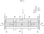
- no frames are arranged in a region 50 (the region illustrated with halftone dots in FIG. 3 ) surrounded by the upper frame 7, the lower frame 8, and the pair of rear side frames 3. That is, between the upper connecting portion 7b of the upper frame 7 and the lower connecting portion 8b of the lower frame 8, there is no structure that opposes the load input from above. Therefore, when the load F is input from above, other frames do not hinder the crushing in the vehicle height direction D3 of the fragile portions 40 located between the upper frame 7 and the lower frame 8. Because of this, the region 50 described above can be referred to as a region (crumble zone) that does not hinder the crushing of the fragile portions 40.
- the rear side frames 3 of the present embodiment each include: an inner frame 31 vertically divided; and an outer frame 32 disposed outside in the vehicle width direction D2 of the inner frame 31 and forming a closed cross section with the inner frame 31.
- the inner frame 31 and the outer frame 32 are coupled to each other by, for example, welding.
- FIG. 4 illustrates, of the pair of rear side frames 3, only the rear side frame 3 disposed on the right side.
- the inner frame 31 is divided into an upper member 33 and a lower member 34 which are arranged with an interval in the vehicle height direction D3.
- Each of the upper member 33 and the lower member 34 forms a hat-shaped cross section, and two flanges 35 extending from a web 36 are disposed in a posture that faces the outer frame 32 (outside in the vehicle width direction D2).
- the present embodiment exemplifies: the lower member 34 in which the web 36 and the flanges 35 extend straight along the vehicle height direction D3; and the upper member 33 disposed above the lower member 34 and extending in a curved posture such that the web 36 and the flanges 35 thereof smoothly connect to the rear roof frame 5.
- the outer frame 32 of the present embodiment forms a hat-shaped cross section of one size larger than that of the inner frame 31, and two flanges 38 extending from a web 37 are disposed in a posture that faces the inner frame 31 (inside in the vehicle width direction D2).
- the web 37 of the outer frame 32 is joined to the flanges 35 of the inner frame 31 (the upper member 33 and the lower member 34).
- the web 36 of the inner frame 31 and the flanges 38 of the outer frame 32 are disposed so as to be flush with each other.
- the closed cross section is formed by the inner frame 31 and the web 37 of the outer frame 32, and a hollow surrounded by this closed cross section extends in the vehicle height direction D3.
- a bead 39 for reinforcement is formed in a linear shape extending in the vehicle height direction D3.
- the bead 39 forms, for example, a recess dented inward (toward the inner frame 31) in the vehicle width direction D2.
- the bead 39 extending in the vehicle height direction D3 as such has a function of increasing rigidity against a compressive load in the vehicle height direction D3.
- the fragile portion 40 is formed to have a low strength relative to the portions adjacent to the fragile portion 40 in the vehicle height direction D3 as described above. Therefore, when the compressive load in the vehicle height direction D3 is applied to the rear side frame 3, the fragile portion 40 serves as a region (crushable zone) relatively easily crushed.
- the fragile portion 40 is provided in at least one of the pair of rear side frames 3. In the present embodiment, as described above, the pair of rear side frames 3 are formed to be equal to each other, and each of the rear side frames 3 is provided with the fragile portion 40.
- the fragile portion 40 of the present embodiment includes a missing part 41 at which the inner frame 31 is divided and two recesses 42 each extending in the vehicle length direction D1 in the rear side frame 3.
- the two recesses 42 are spaced apart from each other in the vehicle height direction D3.
- the present embodiment exemplifies the recesses 42 arranged at a portion corresponding to the missing part 41 in the outer frame 32.
- the missing part 41 is formed by the interval provided between the upper member 33 and the lower member 34 as described above.
- the closed cross section is formed by the inner frame 31 and the outer frame 32, at the missing part 41 provided between the upper member 33 and the lower member 34, the closed cross section is not formed and the strength is intentionally reduced.
- the missing part 41 is formed to have a strength lower than a strength of an upper portion where the closed cross section is formed by the upper member 33 and a strength of a lower portion where the closed cross section is formed by the lower member 34. Accordingly, when the compressive load in the vehicle height direction D3 is applied to the rear side frame 3, the missing part 41 is relatively easily crushed.
- the two recesses 42 are formed in straight lines extending in the vehicle length direction D1 along a lower edge of the upper member 33 and an upper edge of the lower member 34, respectively.
- Each of the recesses 42 is dented, for example, inward in the vehicle width direction D2, and has a structure similar to that of the bead 39 described above.
- the recesses 42 extending in the vehicle length direction D1 serve as base points (buckling points) that bend when the compressive load in the vehicle height direction D3 is applied. That is, as compared with the portions adjacent in the vehicle height direction D3, each of the recesses 42 has a lower strength against the compressive load in the vehicle height direction D3.
- the fragile portion 40 including the recesses 42 bends along the recesses 42, and the portion between the two recesses 42 is deformed so as to be crushed in the vehicle height direction D3.
- the dimension H1 (hereinafter, also referred to as height dimension H1) in the vehicle height direction D3 of the fragile portion 40 is set to be equal to the height difference H2 between the front side frames 2 and the rear side frames 3.
- the height dimension H1 of the fragile portion 40 is set such that, when the entire fragile portion 40 is crushed in the vehicle height direction D3, the respective heights (positions in the vehicle height direction D3) of the upper end of the front side frame 2 and the upper end of the rear side frame 3 come to be substantially equal.
- the height dimension H1 of the fragile portion 40 does not have to be exactly the same as the height difference H2 between the front side frames 2 and the rear side frames 3, and some errors are allowed.
- the front side frames 2 may have structures which form closed cross sections as the rear side frames 3 do. Further, on the front side frames 2, beads similar to the above bead 39 for reinforcement may be formed in linear shapes extending in the vehicle height direction D3. However, the fragile portion 40 is not provided in the front side frames 2. Therefore, in the front side frames 2, the strength is secured over the entire area in the vehicle height direction D3.
- a downward load F is assumed to be input to the high roof structure 1 from a horizontal plane H (plane that extends along the vehicle length direction D1 and the vehicle width direction D2) located above the truck 11.
- a compressive load in the vehicle height direction D3 is applied to the rear side frames 3.
- the fragile portions 40 formed to have a relatively low strength are first crushed in the vehicle height direction D3.
- the rear side frames 3 are compressed in the vehicle height direction D3, which reduces the height difference H2 between the front side frames 2 and the rear side frames 3. Consequently, after the rear side frames 3 are compressed to the same height as that of the front side frames 2, the downward load F is input to the front side frames 2 from the horizontal plane H as well as to the rear side frames 3.
- the load F is distributed not only to the rear side frames 3, but also to the front side frames 2, so that the load F is suppressed from concentrating on the rear side frames 3. Therefore, after the fragile portions 40 are crushed, large deformation of the rear side frames 3 is suppressed. Namely, in the rear side frames 3, since portions other than the fragile portions 40 are formed to have a relatively high strength, after the fragile portions 40 are crushed, the portions other than the fragile portions 40 oppose the load F to suppress large deformation. Because of this, the rear side frames 3 are hardly compressed to positions lower than the front side frames 2.
- both the front side frames 2 and the rear side frames 3 can function as tension rods to act against the load F. Therefore, the strength can be secured against the load F from above. Hence, the deformation of the cab body 10 can be suppressed.
- the load F input to the roof panel 20 from above can be transmitted to each of the front side frames 2 through the front roof frame 4.
- the front roof frame 4 functions as a tension rod, the front side frames 2 can be suppressed from collapsing inward in the vehicle width direction D2.
- the load F input to the roof panel 20 from above can be transmitted to each of the rear side frames 3 through the rear roof frame 5.
- the rear roof frame 5 functions as a tension rod, the rear side frames 3 can be suppressed from collapsing inward in the vehicle width direction D2.
- the load F when the load F is input from above, the load F can be more reliably distributed to each of the front side frames 2 and rear side frames 3. Therefore, each of the front side frames 2 and rear side frames 3 can more reliably oppose the load F input from above. Thus, the deformation of the cab body 10 can be further suppressed.
- the load F input to the roof panel 20 from above can be transmitted from the long roof frame 6 to the front side frames 2 and the rear side frames 3 through the front roof frame 4 and the rear roof frame 5, respectively.
- the front roof frame 4 and the rear roof frame 5 are reinforced by the long roof frame 6, the front side frames 2 and the rear side frames 3 can be more reliably suppressed from collapsing inward in the vehicle width direction D2.
- the load F when the load F is input from above, the load F can be further reliably distributed to each of the front side frames 2 and the rear side frames 3. Therefore, each of the front side frames 2 and rear side frames 3 can more reliably oppose the load F input from above. Thus, the deformation of the cab body 10 can be further suppressed.
- the rear side frames 3 with the crushed fragile portion 40 can be equal to the front side frame 2 in height. This causes the load F to be more reliably distributed to both the front side frames 2 and the rear side frames 3, and thus, the load F can be more reliably suppressed from concentrating on the rear side frames 3. Therefore, the deformation of the cab body 10 can be further suppressed.
- the rear side frames 3 forming the closed cross section by the inner frame 31 and the outer frame 32 since the rigidity increases as compared with the structure without the closed cross section, crushing can be suppressed at portions forming the closed cross section. As a result, the rear side frames 3 can further oppose the load F from above, so that the deformation of the cab body 10 can be further suppressed.
- the fragile portion 40 including the missing part 41 at which the inner frame 31 is divided, in the rear side frames 3, the fragile portion 40 can certainly have a low strength relative to the portions at which the closed cross section is formed.
- the fragile portion 40 of the rear side frames 3 can be more reliably crushed.
- the load F is more reliably distributed to both the front side frames 2 and the rear side frames 3, so that the deformation of the cab body 10 can be further suppressed.
- the missing part 41 is formed by the division of the inner frame 31 disposed on the inside in the vehicle width direction D2 of the outer frame 32, the missing part 41 can be covered by the outer frame 32 from the outside in the vehicle width direction D2. Therefore, as compared with a case where the missing part 41 is exposed to the outside in the vehicle width direction D2, it is possible to secure facility in attaching the roof panel 20 to the rear side frames 3 and strength for supporting the roof panel 20 by the rear side frames 3.
- the fragile portion 40 including the two recesses 42 that each extend in the vehicle length direction D1 in the rear side frames 3 and that are spaced apart from each other in the vehicle height direction D3, when the load F is input from above, the fragile portion 40 can buckle at the recesses 42. This helps the portion between the recesses 42 in the rear side frames 3 easily deform, so that the fragile portion 40 can be more reliably crushed in the vehicle height direction D3. As a result, the load F is more reliably distributed to both the front side frames 2 and the rear side frames 3, and thus, the deformation of the cab body 10 can be further suppressed.
- the rear side frames 3 can be suppressed from collapsing inward in the vehicle width direction D2 without hindering the crushing of the fragile portion 40.
- the respective crushing speeds in the vehicle height direction D3 of the rear side frames 3 can be equal to each other.
- the distribution of the load F to the pair of rear side frames 3 can be equalized. This can suppress not only the deviation of the load F due to the height difference H2 (front-rear difference) between the front side frames 2 and the rear side frames 3, but also the deviation of the load F due to the crushing speed difference (left-right difference) between the pair of rear side frames 3. Therefore, the load F can be more appropriately distributed to each of the front side frames 2 and the rear side frames 3. Hence, the deformation of the cab body 10 can be further suppressed.
- the rear side frames 3 can be reinforced without hindering the crushing of the fragile portion 40. Therefore, the fragile portion 40 of the rear side frames 3 can be more reliably crushed, and after the fragile portion 40 is crushed, large deformation of the rear side frames 3 can be suppressed. As a result, the load F can be more reliably distributed to both the front side frames 2 and the rear side frames 3, so that the deformation of the cab body 10 can be further suppressed.
- the front side frames 2 and the rear side frames 3, which serve as the base are connected by the lower frame 8, so that the high roof structure 1 can be effectively reinforced. Therefore, it is possible to more effectively oppose the load from above by the front side frames 2 and the rear side frames 3. Thus, the deformation of the cab body 10 can be further suppressed.
- a high roof structure 1' according to a second embodiment differs from the high roof structure 1 of the first embodiment described above in that an intake duct 60 is embedded in the cab 12 to which the high roof structure 1' is applied.
- elements identical or corresponding to those described in the first embodiment are denoted by the same reference numbers, and repetitive descriptions thereof will be omitted.
- the intake duct 60 is a device for feeding air to the engine mounted on the truck 11, and includes a snorkel (body) 61 provided at the top of the cab 12 and a non-illustrated duct provided on the rear side of the cab 12.
- the snorkel 61 of the present embodiment is embedded in a right upper rear corner of the cab 12 and takes in the outside air through an opening 62 directed to the right side. Meanwhile, the duct is in communication with the snorkel 61, and is disposed along the rear face of the cab body 10, in the space between the cab body 10 and the mounted object 13.
- a louver 63 is provided in the opening 62.
- the snorkel 61 is installed on the top of a roof panel in a normal roof structure, but is embedded in the roof panel 20 in the high roof structure 1. Specifically, the snorkel 61 is arranged in a concave provided in the roof panel 20. In addition, an outer face of the snorkel 61 and an outer face of the roof panel 20 are formed so as to be smoothly continuous with each other.
- the roof panel 20 of the present embodiment has the concave for accommodating the snorkel 61 as described above, and thus, is in an asymmetrical shape. Accordingly, in the present embodiment, as illustrated in FIG. 9 , among the frames 2 to 9 that support the roof panel 20, the pair of rear side frames 3 have shapes different from each other.
- a first rear side frame 3A arranged on the left side is also referred to as a "left rear side frame 3A”
- a second rear side frame 3B arranged on the right side is also referred to as a "right rear side frame 3B”.
- the fragile portion 40 is provided only in the left rear side frame 3A (the first one of the pair of rear side frames 3).
- the right rear side frame 3B (the second rear side frame 3) on the side where the intake duct 60 is disposed is not provided with the fragile portion 40.
- the left rear side frame 3A provided with the fragile portion 40 has the configuration similar to that of the rear side frames 3 described in the above embodiment.
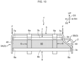
- the right rear side frame 3B without the fragile portion 40 includes a bent portion 30 bent inward in the vehicle width direction D2 for arranging the intake duct 60.
- the bent portion 30 has a shape corresponding to the above-described concave provided in the roof panel 20. Such a bent portion 30 is provided only in the right rear side frame 3B on the side where the intake duct 60 is disposed, and is not provided in the left rear side frame 3A on the opposite side.
- the right rear side frame 3B of the present embodiment includes: a lower portion 3c extending upward substantially straight from the side face 15 on the right side; the above-mentioned bent portion 30 obliquely bent inward in the vehicle width direction D2 (to the left side in the present embodiment) and upward from the lower portion 3c; and an upper portion 3d extending upward substantially straight from the bent portion 30.
- the bent portion 30 is provided between the lower portion 3c and the upper portion 3d as such, the upper portion 3d is disposed above and on the inside in the vehicle width direction D2 from the lower portion 3c.
- the right rear side frame 3B may have a structure that forms a closed cross section in a similar manner to the left rear side frame 3A. Further, in the right rear side frame 3B, a bead similar to the above bead 39 for reinforcement may be formed in a linear shape extending in the vehicle height direction D3.
- the right rear side frame 3B of the present embodiment has the bent portion 30 bent inward in the vehicle width direction D2, as compared with one without the bent portion 30, the right rear side frame 3B easily collapses inward in the vehicle width direction D2 when the load F is input from above, and is easily crushed in the vehicle height direction D3. Due to this, if the fragile portion 40 is not provided in either one of the rear side frames 3, the crushing speed difference easily occurs between the left rear side frame 3A and the right rear side frame 3B.
- the fragile portion 40 is provided only in the left rear side frame 3A, when the load F is input from above, the fragile portion 40 of the left rear side frame 3A is crushed in the vehicle height direction D3.
- the distribution of the load F to the pair of rear side frames 3 can be equalized. This can suppress not only the deviation of the load F due to the height difference H2 between the front side frames 2 and the rear side frames 3, but also the deviation of the load F due to the crushing speed difference between the pair of rear side frames 3. Hence, the deformation of the cab body 10 can be further suppressed.
- the right rear side frame 3B can be suppressed from collapsing inward in the vehicle width direction D2 without hindering the crushing of the fragile portion 40 as described above.
- the respective crushing speeds in the vehicle height direction D3 of the rear side frames 3 can be equal to each other as described above. Therefore, even in cases where the bent portion 30 is provided in either one of the rear side frames 3, it is possible to suppress the deviation of the load F in the front side frames 2 and the rear side frames 3 as described above. Thus, the deformation of the cab body 10 can be further suppressed.
- the configuration of the fragile portion 40 described above is an example.
- the fragile portion 40 may omit the missing part 41 or the recesses 42, or may be formed by a configuration other than the missing part 41 and the recesses 42.
- the configuration of the rear side frames 3 described above is also an example.
- the closed cross section of the rear side frames 3 may be formed by, for example, joining the above-described outer frame 32 having the hat-shaped cross section and an inner frame in a flat plate shape, or may be formed by a single tube member.
- the rear side frames 3 may have a structure that does not form a closed cross section.
- the structure of the front side frames 2 is not particularly limited, either.
- the high roof structures 1 and 1' may be any configuration as long as the high roof structures 1 and 1' include the pair of front side frames 2, the pair of rear side frames 3, and at least one fragile portion 40. As such, even if the front roof frame 4, the rear roof frame 5, etc. are omitted, according to the high roof structures 1 and 1', since the fragile portion 40 is provided, the deformation of the cab body 10 can be suppressed against the load F from above as described above.
- the long roof frame 6 may be coupled to at least the front roof frame 4 and the rear roof frame 5. Thus, the long roof frame 6 may omit the extension portion 6a coupled to the rear side frame 3.
- the lower frame 8 may be coupled to at least the rear side frames 3, and may be uncoupled from the front side frames 2. When not coupled to the front side frames, the lower frame 8 doesn't have to extend to the front side further than the rear side frames 3.
- the above second embodiment illustrates the intake duct 60 provided on the upper right side of the cab 12, but contrary to this, the intake duct 60 may be provided on the upper left side of the cab 12.
- the bent portion 30 may be provided in the left rear side frame 3A and the fragile portion 40 may be provided only in the right rear side frame 3B.
- the specific shape of the bent portion 30 can be appropriately changed in accordance with the shape of the intake duct 60.
- a high roof structure of a truck the high roof structure being mounted on a cab body that has an open ceiling and being provided with a roof panel that inclines so as to gradually increase a vehicle height from a front side to a rear side, the high roof structure comprising:
- the high roof structure according to appendix 2 further comprising a long roof frame that extends in an inclined manner along the roof panel from a front face disposed in front of the pair of side faces in the cab body and that is coupled to the front roof frame and the rear roof frame.
- the high roof structure according to any one of appendices 1 to 3, wherein a dimension in the vehicle height direction of the fragile portion is set to be equal to a height difference between the front side frames and the rear side frames.
- the high roof structure according to any one of appendices 1 to 5, wherein the fragile portion includes two recesses that each extend in a vehicle length direction in the rear side frames and that are spaced apart from each other in the vehicle height direction.
- the high roof structure according to any one of appendices 1 to 6, further comprising an upper frame that connects the rear side frames to each other on the rear side of the rear side frames and above the fragile portion.
- the high roof structure according to any one of appendices 1 to 7, further comprising a lower frame that connects the rear side frames to each other on the rear side of the rear side frames and below the fragile portion.
Landscapes
- Engineering & Computer Science (AREA)
- Mechanical Engineering (AREA)
- Chemical & Material Sciences (AREA)
- Combustion & Propulsion (AREA)
- Transportation (AREA)
- Body Structure For Vehicles (AREA)
Abstract
Description
- The present disclosure relates to a high roof structure applied to a cab of a truck.
- For example, heavy-duty trucks sometimes adopt a high roof structure which provides a roof panel at a higher position than a normal position to expand a compartment formed in a cab. Such a high roof structure is mounted on a cab body having an open ceiling (see, for example, Patent Literature 1).
- [Patent Document 1]
JP 2017-144967 A - The cab with the high roof structure as described above has a small vehicle height difference from a mounted object such as a cargo box disposed behind, and thus, it is difficult to mount a drag foiler (air deflector) for reducing air resistance during traveling. In view of this, in order to reduce traveling resistance without using a drag foiler, some high roof structures adopt a roof panel that inclines so as to gradually increase the vehicle height from a front side to a rear side.
- In the high roof structure with such an inclined roof panel, when a load is input from above, the load tends to concentrate on a rear portion where the vehicle height is relatively high. For this reason, in the high roof structure, since the rear portion is largely crushed before a front portion receives the load, deformation may extend to the cab body. Therefore, the conventional high roof structure has room for improvement in suppressing the deformation of the cab body by securing strength against the load from above.
- The present disclosure has been devised in view of the above-mentioned problems, and an object thereof is to suppress deformation of a cab body against a load from above.
- The present disclosure has been made to solve at least a part of the above problems, and can be realized as the following aspects or application examples.
- (1) A high roof structure of a truck according to the present application example, which is mounted on a cab body that has an open ceiling and provided with a roof panel that inclines so as to gradually increase a vehicle height from a front side to a rear side, includes: a pair of front side frames that respectively erect from a pair of side faces spaced apart from each other in a vehicle width direction in the cab body and that support the roof panel; a pair of rear side frames that respectively erect from the pair of side faces on the rear side of the front side frames to be higher than the front side frames and that support the roof panel; and a fragile portion provided in at least one of the rear side frames and having a low strength relative to portions adjacent to the fragile portion in a vehicle height direction.
- According to the present application example, since the rear side frames erect higher than the front side frames, a load input from above is first input to the rear side frames before being input to the front side frames. As a result, a compressive load in the vehicle height direction acts on the rear side frames, which causes the fragile portion having a relatively low strength to be crushed first in the vehicle height direction, reducing the height difference between the front side frames and the rear side frames. Then, after the rear side frames are compressed to the same height as the front side frames, a downward load is input to the front side frames as well as to the rear side frames.
- Accordingly, the load is distributed not only to the rear side frames but also to the front side frames, so that the load is inhibited from concentrating on the rear side frames. Therefore, after the fragile portion is crushed, large deformation of the rear side frames is suppressed. As such, according to the present application example, when the load is input from above, since the fragile portion is crushed first, both the front side frames and the rear side frames can function as tension rods to act against the load. Therefore, the strength can be secured against the load from above. Hence, the deformation of the cab body can be suppressed.
- (2) The high roof structure according to the present application example may include: a front roof frame that connects respective upper ends of the front side frames to each other; and a rear roof frame that connects respective upper ends of the rear side frames to each other.
- According to such a configuration, the load input from above can be transmitted to each of the front side frames and the rear side frames through the front roof frame and the rear roof frame. In addition, since the front roof frame and the rear roof frame function as tension rods, the front side frames and the rear side frames can be suppressed from collapsing inward in the vehicle width direction.
- For these reasons, when the load is input from above, the load can be more reliably distributed to each of the front side frames and the rear side frames. Therefore, each of the front side frames and the rear side frames can more reliably oppose the load input from above. Thus, the deformation of the cab body can be further suppressed.
- (3) The high roof structure according to the present application example may include: a long roof frame that extends in an inclined manner along the roof panel from a front face disposed in front of the pair of side faces in the cab body and that is coupled to the front roof frame and the rear roof frame.
- According to such a configuration, the load input from above can be transmitted from the long roof frame to the front side frames and the rear side frames through the front roof frame and the rear roof frame, respectively. In addition, since the front roof frame and the rear roof frame are reinforced by the long roof frame, the front side frames and the rear side frames can be more reliably suppressed from collapsing inward in the vehicle width direction.
- For these reasons, when the load is input from above, the load can be further reliably distributed to each of the front side frames and the rear side frames. Therefore, each of the front side frames and the rear side frames can more reliably oppose the load input from above. Thus, the deformation of the cab body can be further suppressed.
- (4) In the high roof structure according to the present application example, a dimension in the vehicle height direction of the fragile portion may be set to be equal to a height difference between the front side frames and the rear side frames.
- According to such a configuration, when the load is input from above, the rear side frames with the crushed fragile portion can be equal to the front side frames in height. This causes the load to be more reliably distributed to both the front side frames and the rear side frames, and thus, the load can be more reliably suppressed from concentrating on the rear side frames. Therefore, the deformation of the cab body can be further suppressed.
- (5) In the high roof structure according to the present application example: the rear side frames may include an inner frame and an outer frame that is disposed outside the inner frame in the vehicle width direction and that forms a closed cross section with the inner frame; and the fragile portion may include a missing part at which the inner frame is divided.
- According to such a configuration, in the rear side frames, the fragile portion can certainly have a low strength relative to the portion at which the closed cross section is formed. Thus, when the load is input from above, the fragile portion of the rear side frames can be more reliably crushed. As a result, the load is more reliably distributed to both the front side frames and the rear side frames, so that the deformation of the cab body can be further suppressed.
- (6) In the high roof structure according to the present application example, the fragile portion may include two recesses that each extend in a vehicle length direction in the rear side frames and that are spaced apart from each other in the vehicle height direction.
- According to such a configuration, when the load is input from above, the fragile portion can buckle at the recesses. This helps the portion between the recesses in the rear side frames easily deform, so that the fragile portion can be more reliably crushed in the vehicle height direction. As a result, the load is more reliably distributed to both the front side frames and the rear side frames, and thus, the deformation of the cab body can be further suppressed.
- (7) The high roof structure according to the present application example may include an upper frame that connects the rear side frames to each other on the rear side of the rear side frames and above the fragile portion.
- According to such a configuration, when the load is input from above, the rear side frames can be suppressed from collapsing inward in the vehicle width direction without hindering the crushing of the fragile portion. In addition, according to the upper frame, when the load is input from above, the respective crushing speeds in the vehicle height direction of the rear side frames can be equal to each other.
- Thus, distribution of the load to the pair of rear side frames can be equalized. This can suppress not only the deviation of the load due to the height difference (front-rear difference) between the front side frames and the rear side frames, but also the deviation of the load due to the crushing speed difference (left-right difference) between the pair of rear side frames. Therefore, the load can be more appropriately distributed to each of the front side frames and the rear side frames. Hence, the deformation of the cab body can be further suppressed.
- (8) The high roof structure according to the present application example may include a lower frame that connects the rear side frames to each other on the rear side of the rear side frames and below the fragile portion.
- According to such a configuration, when the load is input from above, the rear side frames can be reinforced without hindering the crushing of the fragile portion. Therefore, the fragile portion of the rear side frames can be more reliably crushed, and after the crushing of the fragile portion, large deformation of the rear side frames can be suppressed. As a result, the load can be more reliably distributed to both the front side frames and the rear side frames, so that the deformation of the cab body can be further suppressed.
- (9) In the high roof structure according to the present application example: the fragile portion may be provided only in a first one of the rear side frames; and a second one of the rear side frames, in which the fragile portion is not provided, may include a bent portion bent inward in the vehicle width direction for arranging an intake duct.
- As compared with a rear side frame without the bent portion, the rear side frame with the bent portion easily collapses inward in the vehicle width direction when the load is input from above, and is easily crushed in the vehicle height direction. Due to this, if the fragile portion is not provided in either one of the rear side frames, the crushing speed difference easily occurs between the pair of rear side frames.
- In contrast, if the fragile portion is provided only in the first one of the rear side frames, when the load is input from above, the fragile portion of the first one of the rear side frames is crushed in the vehicle height direction. This causes the first one of the rear side frames to be compressed in the vehicle height direction, so that even if the second one of the rear side frames, which includes the bent portion, collapses inward in the vehicle width direction, the crushing speed difference can be reduced between the pair of rear side frames.
- Therefore, even in cases where the bent portion is provided in the second one of the rear side frames, the distribution of the load to the pair of rear side frames can be equalized. This can suppress not only the deviation of the load due to the height difference between the front side frames and the rear side frames, but also the deviation of the load due to the crushing speed difference between the pair of rear side frames. Hence, the deformation of the cab body can be further suppressed.
- According to the present disclosure, the deformation of the cab body can be suppressed against the load from above.
-
-
FIG. 1 is a perspective view of a front portion of a truck to which a high roof structure according to a first embodiment is applied. -
FIG. 2 is a perspective view of the high roof structure ofFIG. 1 omitting a roof panel. -
FIG. 3 is a rear view of the high roof structure ofFIG. 2 . -
FIG. 4 is an exploded perspective view of a rear side frame included in the high roof structure ofFIG. 2 . -
FIG. 5 is a cross-sectional view (X-X arrow sectional view ofFIG. 4 ) illustrating a structure of a closed cross section of the rear side frame ofFIG. 4 . -
FIG. 6 is a right side view illustrating the high roof structure ofFIG. 2 together with an upper portion of a cab body. -
FIG. 7 is a schematic right side view explaining effects of the high roof structure ofFIG. 2 . -
FIG. 8 is a perspective view (diagram corresponding toFIG. 1 ) of a front portion of a truck to which a high roof structure according to a second embodiment is applied -
FIG. 9 is a perspective view (diagram corresponding toFIG. 2 ) of the high roof structure ofFIG. 8 omitting a roof panel. -
FIG. 10 is a rear view (diagram corresponding toFIG. 3 ) of the high roof structure ofFIG. 9 . - Embodiments of the present disclosure will now be described with reference to drawings. The following embodiments are merely illustrative and are not intended to preclude the application of various modifications and techniques not explicitly set forth in the embodiments. Each configuration of the following embodiments can be implemented by various modifications without departing from the gist thereof. Also, it can be selected as necessary, or can be combined as appropriate.
- As illustrated in
FIG. 1 , ahigh roof structure 1 of a truck according to a first embodiment (hereinafter, also simply referred to as "high roof structure 1") is applied to acab 12 of atruck 11. Thetruck 11 is, for example, a heavy-duty truck of a cab over type, and is equipped with a non-illustrated engine disposed below thecab 12. Behind thecab 12, a mountedobject 13 such as a cargo box is mounted. In the drawings, a front side (forward direction) of thetruck 11 is indicated as "FR", an upper side of thetruck 11 is indicated as "UP", and a right side of thetruck 11 is indicated as "RH". - In the
high roof structure 1, to expand a compartment formed in thecab 12, aroof panel 20 that forms a top surface of thecab 12 is provided at a higher position as compared to a normal roof structure. Thecab 12 with thehigh roof structure 1 as described above is also referred to as a "high roof cab" and thetruck 11 with thehigh roof structure 1 is also referred to as a "high roof vehicle". In the high roof cab and the high roof vehicle, the compartment is expanded upward by thehigh roof structure 1, so that habitability of the compartment is enhanced. This elevates comfortableness when the driver, the passenger, etc. rests (for example, takes a nap) in the compartment during long distance travels. - In the
high roof structure 1, theroof panel 20 is mounted on acab body 10 that has an open ceiling by, for example, spot welding. Thecab body 10 is shaped into a substantial box without a lid, and defines the compartment in cooperation with thehigh roof structure 1. Specifically, thecab body 10 includes a pair of side faces 15 spaced apart from each other in a vehicle width direction (left-right direction) D2, afront face 16 disposed in front of the side faces 15, a rear face (not illustrated) disposed behind the side faces 15, and a bottom face (not illustrated) coupled to lower ends of the above-mentioned faces. All of the side faces 15, thefront face 16, and the rear face erect in a vehicle height direction (up-down direction) D3, forming walls of the compartment. Meanwhile, the bottom face is provided so as to extend in a vehicle length direction (front-rear direction) D1 and the vehicle width direction D2, forming a floor surface of the compartment. - In order to reduce the air resistance during traveling of the
truck 11, theroof panel 20 smoothly inclines so as to gradually increase a vehicle height from the front side to the rear side. In thehigh roof structure 1, instead of providing a drag foiler (air deflector), by forming theroof panel 20 itself in an inclined shape as the above, the air resistance is reduced. - The present embodiment illustrates the
roof panel 20 in a symmetrical shape. Specifically, theroof panel 20 includes acentral panel 21 that constitutes the front and the top thereof, and a pair ofside panels 22 respectively disposed on the left and right sides of thecentral panel 21. Thecentral panel 21 and theside panels 22 are integrated by, for example, welding. However, specific configuration of theroof panel 20 is not limited to the above example. - The
high roof structure 1 of the present embodiment includes, as frames that support theroof panel 20,various frames 2 to 9 illustrated inFIG. 2 . Theseframes 2 to 9 are arranged inside the roof panel 20 (in a space below thecentral panel 21 and between the side panels 22). Thus, theframes 2 to 9 are all covered by theroof panel 20, and are not exposed to exteriors of thetruck 11 and thecab 12. - In detail, the
frames 2 to 9 are: front side frames 2 and rear side frames 3, each of which is a longitudinal member that extends in the vehicle height direction D3; a front roof frame 4, arear roof frame 5, anupper frame 7, and alower frame 8, each of which is a lateral member that extends in a horizontal direction (the vehicle length direction D1 and/or the vehicle width direction D2); and along roof frame 6 and anauxiliary roof frame 9, each of which extends in an inclined manner along theroof panel 20. Incidentally, the front roof frame 4, therear roof frame 5, thelong roof frame 6, and theauxiliary roof frame 9 that support thecentral panel 21 of theroof panel 20 may be integrated (or partially integrated) as a single center frame. - The front side frames 2 and the rear side frames 3 are provided in pairs, forming four legs that support the
roof panel 20. In detail, the front side frames 2 form front legs and the rear side frames 3 form rear legs. In thehigh roof structure 1, four of the front side frames 2 and the rear side frames 3 mainly oppose a load F input from above. - The pair of front side frames 2 respectively erect from the pair of side faces 15 of the
cab body 10 and are arranged along theside panels 22. The present embodiment illustrates the front side frames 2 that extend upward from the side faces 15 and then smoothly curve inward in the vehicle width direction D2. - In contrast, the pair of rear side frames 3 respectively erect from the pair of side faces 15 of the
cab body 10 on the rear side of the front side frames 2 and are arranged along the pair ofside panels 22. The rear side frames 3 erect higher than the front side frames 2. That is, upper ends of the rear side frames 3 are positioned higher than upper ends of the front side frames 2. In the present embodiment, the entire parts of the rear side frames 3 erect upward substantially straight from the side faces 15. - In the present embodiment, since the
roof panel 20 is in a symmetrical shape, the pair of front side frames 2 are shaped equally (mirror-symmetrical with respect to the center in the vehicle width direction D2) and the pair of rear side frames 3 are also shaped equally. However, the pair of rear side frames 3 may be shaped differently. In the present embodiment, each of the rear side frames 3 is provided with afragile portion 40 that has a low strength relative to portions adjacent to the fragile portion in the vehicle height direction D3. Specific structures of the rear side frames 3 and thefragile portions 40 will be described later. - Each lower end of the front side frames 2 and the rear side frames 3 is coupled to a part reinforced by a
stiffener 14 in the side faces 15 of thecab body 10. Thestiffener 14 is a member that reinforces a part of the side faces 15, and is provided, for example, in a space between an outer panel (a face on the outside in the vehicle width direction D2) of theside face 15 and an inner panel (a face on the inside in the vehicle width direction D2) of theside face 15. The present embodiment illustrates the side faces 15 each provided with twostiffeners 14 spaced apart from each other in the vehicle length direction D1. - The front roof frame 4 connects the upper ends of the front side frames 2 to each other. The front roof frame 4 functions as a tension rod between the front side frames 2, and thereby, suppresses the front side frames 2 from collapsing inward in the vehicle width direction D2. Similarly, the
rear roof frame 5 connects the upper ends of the rear side frames 3 to each other. Therear roof frame 5 functions as a tension rod between the rear side frames 3, and thereby, suppresses the rear side frames 3 from collapsing inward in the vehicle width direction D2. - Both the front roof frame 4 and the
rear roof frame 5 of the present embodiment extend substantially straight along the vehicle width direction D2. Since the upper ends of the rear side frames 3 are positioned on the rear side of and higher than the upper ends of the front side frames 2 as described above, therear roof frame 5 is disposed on the rear side of and higher than the front roof frame 4. - The
long roof frame 6 extends in the inclined manner along theroof panel 20 from thefront face 16 of thecab body 10 toward the rear side, and is coupled to both the front roof frame 4 and therear roof frame 5. As such, thelong roof frame 6 extends from thefront face 16 of thecab body 10 to at least therear roof frame 5 via the front roof frame 4. Thelong roof frame 6 of the present embodiment has anextension portion 6a that extends rearward and downward further than therear roof frame 5. Theextension portion 6a is coupled to theupper frame 7. - The present embodiment illustrates the
high roof structure 1 in which a pair of long roof frames 6 are spaced apart from each other in the vehicle width direction D2 and oneauxiliary roof frame 9 is disposed between the pair of long roof frames 6. However, the respective numbers of thelong roof frame 6 and theauxiliary roof frame 9 provided in thehigh roof structure 1 are not particularly limited. The long roof frames 6 and theauxiliary roof frame 9 may be omitted from thehigh roof structure 1. - The
auxiliary roof frame 9 is formed to be shorter than thelong roof frame 6, extends in the inclined manner along theroof panel 20 like thelong roof frame 6, and is arranged in parallel with thelong roof frame 6. Theauxiliary roof frame 9 of the present embodiment extends substantially straight from the front roof frame 4 to therear roof frame 5, and connects the front roof frame 4 and therear roof frame 5 to each other. It should be noted that theauxiliary roof frame 9 is not provided with an extension portion that extends rearward or downward further than therear roof frame 5. - As illustrated in
FIGS. 2 and3 , theupper frame 7 connects the rear side frames 3 to each other on the rear side of the rear side frames 3 and above thefragile portions 40. Theupper frame 7 functions as a tension rod between the rear side frames 3, and thereby, suppresses the rear side frames 3 from collapsing inward in the vehicle width direction D2. In addition, theupper frame 7 has a function of equalizing crushing speeds of the rear side frames 3 in the vehicle height direction D3 when the load F is input to thehigh roof structure 1 from above. - In detail, the
upper frame 7 includes: twoupper arm portions 7a coupled to the insides in the vehicle width direction D2 of the rear side frames 3; and an upper connectingportion 7b connecting theupper arm portions 7a to each other on the rear side of the rear side frames 3, and forms a U-shape in which the twoupper arm portions 7a each point forward when viewed from the vehicle height direction D3. The twoupper arm portions 7a of theupper frame 7 are respectively coupled to the pair of rear side frames 3 above thefragile portions 40. To the upper connectingportion 7b of theupper frame 7, theextension portions 6a of the long roof frames 6 are coupled. - The
lower frame 8 connects the rear side frames 3 to each other on the rear side of the rear side frames 3 and below thefragile portions 40. As such, thelower frame 8 is similar to theupper frame 7 in connecting the rear side frames 3 to each other on the rear side of the rear side frames 3, but is different from theupper frame 7 in being disposed below thefragile portions 40. Thelower frame 8 disposed below theupper frame 7 has a function of reinforcing a base of thehigh roof structure 1. - The
lower frame 8 of the present embodiment extends to the front side further than the rear side frames 3 and is coupled to the front side frames 2 as well as the rear side frames 3. Therefore, thelower frame 8 connects the pair of front side frames 2 and the pair of rear side frames 3 which form the four legs in thehigh roof structure 1. - In detail, the
lower frame 8 includes: twolower arm portions 8a extending in the vehicle length direction D1 and coupled to the insides in the vehicle width direction D2 of the front side frames 2 and the rear side frames 3; and a lower connectingportion 8b connecting thelower arm portions 8a to each other on the rear side of the rear side frames 3, and forms a U-shape in which the twolower arm portions 8a each point forward when viewed from the vehicle height direction D3. The twolower arm portions 8a of thelower frame 8 are respectively connected to the pair of rear side frames 3 below thefragile portions 40. On the other hand, to the lower connectingportion 8b of thelower frame 8, none of other frames are coupled. Incidentally, thelower arm portions 8a may be connected to front ends of the long roof frames 6 located in front FR. - As illustrated in
FIG. 3 , in the present embodiment, no frames are arranged in a region 50 (the region illustrated with halftone dots inFIG. 3 ) surrounded by theupper frame 7, thelower frame 8, and the pair of rear side frames 3. That is, between the upper connectingportion 7b of theupper frame 7 and the lower connectingportion 8b of thelower frame 8, there is no structure that opposes the load input from above. Therefore, when the load F is input from above, other frames do not hinder the crushing in the vehicle height direction D3 of thefragile portions 40 located between theupper frame 7 and thelower frame 8. Because of this, theregion 50 described above can be referred to as a region (crumble zone) that does not hinder the crushing of thefragile portions 40. - As illustrated in
FIG. 4 , the rear side frames 3 of the present embodiment each include: aninner frame 31 vertically divided; and anouter frame 32 disposed outside in the vehicle width direction D2 of theinner frame 31 and forming a closed cross section with theinner frame 31. Theinner frame 31 and theouter frame 32 are coupled to each other by, for example, welding.FIG. 4 illustrates, of the pair of rear side frames 3, only therear side frame 3 disposed on the right side. - Specifically, the
inner frame 31 is divided into anupper member 33 and alower member 34 which are arranged with an interval in the vehicle height direction D3. Each of theupper member 33 and thelower member 34 forms a hat-shaped cross section, and twoflanges 35 extending from aweb 36 are disposed in a posture that faces the outer frame 32 (outside in the vehicle width direction D2). The present embodiment exemplifies: thelower member 34 in which theweb 36 and theflanges 35 extend straight along the vehicle height direction D3; and theupper member 33 disposed above thelower member 34 and extending in a curved posture such that theweb 36 and theflanges 35 thereof smoothly connect to therear roof frame 5. - Meanwhile, the
outer frame 32 of the present embodiment forms a hat-shaped cross section of one size larger than that of theinner frame 31, and twoflanges 38 extending from aweb 37 are disposed in a posture that faces the inner frame 31 (inside in the vehicle width direction D2). As illustrated inFIG. 5 , theweb 37 of theouter frame 32 is joined to theflanges 35 of the inner frame 31 (theupper member 33 and the lower member 34). When theinner frame 31 and theouter frame 32 are joined to each other as such, theweb 36 of theinner frame 31 and theflanges 38 of theouter frame 32 are disposed so as to be flush with each other. - In the
rear side frame 3, the closed cross section is formed by theinner frame 31 and theweb 37 of theouter frame 32, and a hollow surrounded by this closed cross section extends in the vehicle height direction D3. Thus, according to therear side frame 3 with the closed cross section formed by accommodating theinner frame 31 with a relatively small hat-shaped cross section in theouter frame 32 with a relatively large hat-shaped cross section, rigidity can be increased while achieving compactification. - On the
web 37 of theouter frame 32 of the present embodiment, abead 39 for reinforcement is formed in a linear shape extending in the vehicle height direction D3. Thebead 39 forms, for example, a recess dented inward (toward the inner frame 31) in the vehicle width direction D2. Thebead 39 extending in the vehicle height direction D3 as such has a function of increasing rigidity against a compressive load in the vehicle height direction D3. - As illustrated in
FIG. 4 , thefragile portion 40 is formed to have a low strength relative to the portions adjacent to thefragile portion 40 in the vehicle height direction D3 as described above. Therefore, when the compressive load in the vehicle height direction D3 is applied to therear side frame 3, thefragile portion 40 serves as a region (crushable zone) relatively easily crushed. Thefragile portion 40 is provided in at least one of the pair of rear side frames 3. In the present embodiment, as described above, the pair of rear side frames 3 are formed to be equal to each other, and each of the rear side frames 3 is provided with thefragile portion 40. - The
fragile portion 40 of the present embodiment includes amissing part 41 at which theinner frame 31 is divided and tworecesses 42 each extending in the vehicle length direction D1 in therear side frame 3. The tworecesses 42 are spaced apart from each other in the vehicle height direction D3. The present embodiment exemplifies therecesses 42 arranged at a portion corresponding to themissing part 41 in theouter frame 32. - The missing
part 41 is formed by the interval provided between theupper member 33 and thelower member 34 as described above. In therear side frame 3, although the closed cross section is formed by theinner frame 31 and theouter frame 32, at themissing part 41 provided between theupper member 33 and thelower member 34, the closed cross section is not formed and the strength is intentionally reduced. Thus, the missingpart 41 is formed to have a strength lower than a strength of an upper portion where the closed cross section is formed by theupper member 33 and a strength of a lower portion where the closed cross section is formed by thelower member 34. Accordingly, when the compressive load in the vehicle height direction D3 is applied to therear side frame 3, the missingpart 41 is relatively easily crushed. - In the
outer frame 32, the tworecesses 42 are formed in straight lines extending in the vehicle length direction D1 along a lower edge of theupper member 33 and an upper edge of thelower member 34, respectively. Each of therecesses 42 is dented, for example, inward in the vehicle width direction D2, and has a structure similar to that of thebead 39 described above. However, in contrast to thebead 39 extending in the vehicle height direction D3, therecesses 42 extending in the vehicle length direction D1 serve as base points (buckling points) that bend when the compressive load in the vehicle height direction D3 is applied. That is, as compared with the portions adjacent in the vehicle height direction D3, each of therecesses 42 has a lower strength against the compressive load in the vehicle height direction D3. Therefore, when the compressive load in the vehicle height direction D3 is applied to therear side frame 3, thefragile portion 40 including therecesses 42 bends along therecesses 42, and the portion between the tworecesses 42 is deformed so as to be crushed in the vehicle height direction D3. - As illustrated in
FIG. 6 , the dimension H1 (hereinafter, also referred to as height dimension H1) in the vehicle height direction D3 of thefragile portion 40 is set to be equal to the height difference H2 between the front side frames 2 and the rear side frames 3. In other words, the height dimension H1 of thefragile portion 40 is set such that, when the entirefragile portion 40 is crushed in the vehicle height direction D3, the respective heights (positions in the vehicle height direction D3) of the upper end of thefront side frame 2 and the upper end of therear side frame 3 come to be substantially equal. However, the height dimension H1 of thefragile portion 40 does not have to be exactly the same as the height difference H2 between the front side frames 2 and the rear side frames 3, and some errors are allowed. - Although not illustrated in detail, the front side frames 2 may have structures which form closed cross sections as the rear side frames 3 do. Further, on the front side frames 2, beads similar to the
above bead 39 for reinforcement may be formed in linear shapes extending in the vehicle height direction D3. However, thefragile portion 40 is not provided in the front side frames 2. Therefore, in the front side frames 2, the strength is secured over the entire area in the vehicle height direction D3. -
- (1) In the
high roof structure 1 with theroof panel 20 that inclines so as to gradually increase the vehicle height from the front side to the rear side as described above, the rear side frames 3 erect higher than the front side frames 2. Because of this, the load F input to thehigh roof structure 1 from above is first input to the rear side frames 3 before being input to the front side frames 2. - For example, in a regulation test, a downward load F is assumed to be input to the
high roof structure 1 from a horizontal plane H (plane that extends along the vehicle length direction D1 and the vehicle width direction D2) located above thetruck 11. In this case, since the load F is input from the horizontal plane H, a compressive load in the vehicle height direction D3 is applied to the rear side frames 3. Then, in the rear side frames 3, thefragile portions 40 formed to have a relatively low strength are first crushed in the vehicle height direction D3. - As illustrated in
FIG. 7 , when thefragile portions 40 are crushed in the vehicle height direction D3, the rear side frames 3 are compressed in the vehicle height direction D3, which reduces the height difference H2 between the front side frames 2 and the rear side frames 3. Consequently, after the rear side frames 3 are compressed to the same height as that of the front side frames 2, the downward load F is input to the front side frames 2 from the horizontal plane H as well as to the rear side frames 3. - As a result, the load F is distributed not only to the rear side frames 3, but also to the front side frames 2, so that the load F is suppressed from concentrating on the rear side frames 3. Therefore, after the
fragile portions 40 are crushed, large deformation of the rear side frames 3 is suppressed. Namely, in the rear side frames 3, since portions other than thefragile portions 40 are formed to have a relatively high strength, after thefragile portions 40 are crushed, the portions other than thefragile portions 40 oppose the load F to suppress large deformation. Because of this, the rear side frames 3 are hardly compressed to positions lower than the front side frames 2. - Therefore, according to the
high roof structure 1, when the load F is input from above, since thefragile portion 40 is crushed first, both the front side frames 2 and the rear side frames 3 can function as tension rods to act against the load F. Therefore, the strength can be secured against the load F from above. Hence, the deformation of thecab body 10 can be suppressed. - (2) According to the front roof frame 4 that connects the upper ends of the front side frames 2 to each other, the load F input to the
roof panel 20 from above can be transmitted to each of the front side frames 2 through the front roof frame 4. In addition, since the front roof frame 4 functions as a tension rod, the front side frames 2 can be suppressed from collapsing inward in the vehicle width direction D2. - Similarly, according to the
rear roof frame 5 that connects the upper ends of the rear side frames 3 to each other, the load F input to theroof panel 20 from above can be transmitted to each of the rear side frames 3 through therear roof frame 5. In addition, since therear roof frame 5 functions as a tension rod, the rear side frames 3 can be suppressed from collapsing inward in the vehicle width direction D2. - For these reasons, when the load F is input from above, the load F can be more reliably distributed to each of the front side frames 2 and rear side frames 3. Therefore, each of the front side frames 2 and rear side frames 3 can more reliably oppose the load F input from above. Thus, the deformation of the
cab body 10 can be further suppressed. - (3) According to the
long roof frame 6 that extends in the inclined manner along theroof panel 20 and that is coupled to the front roof frame 4 and therear roof frame 5, the load F input to theroof panel 20 from above can be transmitted from thelong roof frame 6 to the front side frames 2 and the rear side frames 3 through the front roof frame 4 and therear roof frame 5, respectively. In addition, since the front roof frame 4 and therear roof frame 5 are reinforced by thelong roof frame 6, the front side frames 2 and the rear side frames 3 can be more reliably suppressed from collapsing inward in the vehicle width direction D2. - For these reasons, when the load F is input from above, the load F can be further reliably distributed to each of the front side frames 2 and the rear side frames 3. Therefore, each of the front side frames 2 and rear side frames 3 can more reliably oppose the load F input from above. Thus, the deformation of the
cab body 10 can be further suppressed. - (4) If the height dimension H1 of the
fragile portion 40 is set to be equal to the height difference H2 between the front side frames 2 and the rear side frames 3, when the load F is input from above, the rear side frames 3 with the crushedfragile portion 40 can be equal to thefront side frame 2 in height. This causes the load F to be more reliably distributed to both the front side frames 2 and the rear side frames 3, and thus, the load F can be more reliably suppressed from concentrating on the rear side frames 3. Therefore, the deformation of thecab body 10 can be further suppressed. - (5) According to the rear side frames 3 forming the closed cross section by the
inner frame 31 and theouter frame 32, since the rigidity increases as compared with the structure without the closed cross section, crushing can be suppressed at portions forming the closed cross section. As a result, the rear side frames 3 can further oppose the load F from above, so that the deformation of thecab body 10 can be further suppressed. - In addition, according to the
fragile portion 40 including themissing part 41 at which theinner frame 31 is divided, in the rear side frames 3, thefragile portion 40 can certainly have a low strength relative to the portions at which the closed cross section is formed. Thus, when the load F is input from above, thefragile portion 40 of the rear side frames 3 can be more reliably crushed. As a result, the load F is more reliably distributed to both the front side frames 2 and the rear side frames 3, so that the deformation of thecab body 10 can be further suppressed. - Further, since the
missing part 41 is formed by the division of theinner frame 31 disposed on the inside in the vehicle width direction D2 of theouter frame 32, the missingpart 41 can be covered by theouter frame 32 from the outside in the vehicle width direction D2. Therefore, as compared with a case where the missingpart 41 is exposed to the outside in the vehicle width direction D2, it is possible to secure facility in attaching theroof panel 20 to the rear side frames 3 and strength for supporting theroof panel 20 by the rear side frames 3. - (6) According to the
fragile portion 40 including the tworecesses 42 that each extend in the vehicle length direction D1 in the rear side frames 3 and that are spaced apart from each other in the vehicle height direction D3, when the load F is input from above, thefragile portion 40 can buckle at therecesses 42. This helps the portion between therecesses 42 in the rear side frames 3 easily deform, so that thefragile portion 40 can be more reliably crushed in the vehicle height direction D3. As a result, the load F is more reliably distributed to both the front side frames 2 and the rear side frames 3, and thus, the deformation of thecab body 10 can be further suppressed. - (7) According to the
upper frame 7 that connects the rear side frames 3 to each other on the rear side of the rear side frames 3 and above thefragile portion 40, when the load F is input from above, the rear side frames 3 can be suppressed from collapsing inward in the vehicle width direction D2 without hindering the crushing of thefragile portion 40. In addition, according to theupper frame 7, when the load F is input from above, the respective crushing speeds in the vehicle height direction D3 of the rear side frames 3 can be equal to each other. - Thus, the distribution of the load F to the pair of rear side frames 3 can be equalized. This can suppress not only the deviation of the load F due to the height difference H2 (front-rear difference) between the front side frames 2 and the rear side frames 3, but also the deviation of the load F due to the crushing speed difference (left-right difference) between the pair of rear side frames 3. Therefore, the load F can be more appropriately distributed to each of the front side frames 2 and the rear side frames 3. Hence, the deformation of the
cab body 10 can be further suppressed. - (8) According to the
lower frame 8 that connects the rear side frames 3 to each other on the rear side of the rear side frames 3 and below thefragile portion 40, when the load F is input from above, the rear side frames 3 can be reinforced without hindering the crushing of thefragile portion 40. Therefore, thefragile portion 40 of the rear side frames 3 can be more reliably crushed, and after thefragile portion 40 is crushed, large deformation of the rear side frames 3 can be suppressed. As a result, the load F can be more reliably distributed to both the front side frames 2 and the rear side frames 3, so that the deformation of thecab body 10 can be further suppressed. - (9) If a frame extends in the vehicle height direction D3 in the
region 50 surrounded by theupper frame 7, thelower frame 8, and the rear side frames 3, when the load F is input from above, the crushing of thefragile portion 40 may be hindered. On the other hand, if no frames are disposed in theregion 50, the crushing of thefragile portion 40 is not hindered, so that thefragile portion 40 can be more reliably crushed. As a result, the load F can be more reliably distributed to both the front side frames 2 and the rear side frames 3, and thus, the deformation of thecab body 10 can be further suppressed. - (10) According to the
lower frame 8 that extends to the front side further than the rear side frames 3 and that is coupled to the front side frames 2, the front side frames 2 and the rear side frames 3, which serve as the base, are connected by thelower frame 8, so that thehigh roof structure 1 can be effectively reinforced. Therefore, it is possible to more effectively oppose the load from above by the front side frames 2 and the rear side frames 3. Thus, the deformation of thecab body 10 can be further suppressed. - As illustrated in
FIG. 8 , a high roof structure 1' according to a second embodiment differs from thehigh roof structure 1 of the first embodiment described above in that anintake duct 60 is embedded in thecab 12 to which the high roof structure 1' is applied. Hereinafter, elements identical or corresponding to those described in the first embodiment are denoted by the same reference numbers, and repetitive descriptions thereof will be omitted. - The
intake duct 60 is a device for feeding air to the engine mounted on thetruck 11, and includes a snorkel (body) 61 provided at the top of thecab 12 and a non-illustrated duct provided on the rear side of thecab 12. Thesnorkel 61 of the present embodiment is embedded in a right upper rear corner of thecab 12 and takes in the outside air through anopening 62 directed to the right side. Meanwhile, the duct is in communication with thesnorkel 61, and is disposed along the rear face of thecab body 10, in the space between thecab body 10 and the mountedobject 13. Alouver 63 is provided in theopening 62. - The
snorkel 61 is installed on the top of a roof panel in a normal roof structure, but is embedded in theroof panel 20 in thehigh roof structure 1. Specifically, thesnorkel 61 is arranged in a concave provided in theroof panel 20. In addition, an outer face of thesnorkel 61 and an outer face of theroof panel 20 are formed so as to be smoothly continuous with each other. - The
roof panel 20 of the present embodiment has the concave for accommodating thesnorkel 61 as described above, and thus, is in an asymmetrical shape. Accordingly, in the present embodiment, as illustrated inFIG. 9 , among theframes 2 to 9 that support theroof panel 20, the pair of rear side frames 3 have shapes different from each other. Hereinafter, of the pair of rear side frames 3, a firstrear side frame 3A arranged on the left side is also referred to as a "leftrear side frame 3A" and a secondrear side frame 3B arranged on the right side is also referred to as a "rightrear side frame 3B". - In the present embodiment, the
fragile portion 40 is provided only in the leftrear side frame 3A (the first one of the pair of rear side frames 3). In other words, the rightrear side frame 3B (the second rear side frame 3) on the side where theintake duct 60 is disposed is not provided with thefragile portion 40. The leftrear side frame 3A provided with thefragile portion 40 has the configuration similar to that of the rear side frames 3 described in the above embodiment. - On the other hand, the right
rear side frame 3B without thefragile portion 40 includes abent portion 30 bent inward in the vehicle width direction D2 for arranging theintake duct 60. Thebent portion 30 has a shape corresponding to the above-described concave provided in theroof panel 20. Such abent portion 30 is provided only in the rightrear side frame 3B on the side where theintake duct 60 is disposed, and is not provided in the leftrear side frame 3A on the opposite side. - As illustrated in
FIGS. 9 and10 , the rightrear side frame 3B of the present embodiment includes: alower portion 3c extending upward substantially straight from theside face 15 on the right side; the above-mentionedbent portion 30 obliquely bent inward in the vehicle width direction D2 (to the left side in the present embodiment) and upward from thelower portion 3c; and anupper portion 3d extending upward substantially straight from thebent portion 30. In the rightrear side frame 3B, since thebent portion 30 is provided between thelower portion 3c and theupper portion 3d as such, theupper portion 3d is disposed above and on the inside in the vehicle width direction D2 from thelower portion 3c. - To the
upper portion 3d of the rightrear side frame 3B, a first one (on the right side in the present embodiment) of theupper arm portions 7a of theupper frame 7 is coupled. To thelower portion 3c of the rightrear side frame 3B, a first one (on the right side in the present embodiment) of thelower arm portions 8a of thelower frame 8 is coupled. Although not illustrated in detail, the rightrear side frame 3B may have a structure that forms a closed cross section in a similar manner to the leftrear side frame 3A. Further, in the rightrear side frame 3B, a bead similar to theabove bead 39 for reinforcement may be formed in a linear shape extending in the vehicle height direction D3. - Since the right
rear side frame 3B of the present embodiment has the bentportion 30 bent inward in the vehicle width direction D2, as compared with one without thebent portion 30, the rightrear side frame 3B easily collapses inward in the vehicle width direction D2 when the load F is input from above, and is easily crushed in the vehicle height direction D3. Due to this, if thefragile portion 40 is not provided in either one of the rear side frames 3, the crushing speed difference easily occurs between the leftrear side frame 3A and the rightrear side frame 3B. - In contrast, in the high roof structure 1', since the
fragile portion 40 is provided only in the leftrear side frame 3A, when the load F is input from above, thefragile portion 40 of the leftrear side frame 3A is crushed in the vehicle height direction D3. This causes the leftrear side frame 3A to be compressed in the vehicle height direction D3, so that even if the rightrear side frame 3B collapses inward in the vehicle width direction D2, the crushing speed difference can be reduced between the leftrear side frame 3A and the rightrear side frame 3B. - Therefore, according to the high roof structure 1', even in cases where the
bent portion 30 is provided in either one of the rear side frames 3, the distribution of the load F to the pair of rear side frames 3 can be equalized. This can suppress not only the deviation of the load F due to the height difference H2 between the front side frames 2 and the rear side frames 3, but also the deviation of the load F due to the crushing speed difference between the pair of rear side frames 3. Hence, the deformation of thecab body 10 can be further suppressed. - Moreover, according to the
upper frame 7 that connects the leftrear side frame 3A with thefragile portion 40 and the rightrear side frame 3B with thebent portion 30, the rightrear side frame 3B can be suppressed from collapsing inward in the vehicle width direction D2 without hindering the crushing of thefragile portion 40 as described above. Further, according to theupper frame 7, the respective crushing speeds in the vehicle height direction D3 of the rear side frames 3 can be equal to each other as described above. Therefore, even in cases where thebent portion 30 is provided in either one of the rear side frames 3, it is possible to suppress the deviation of the load F in the front side frames 2 and the rear side frames 3 as described above. Thus, the deformation of thecab body 10 can be further suppressed. - In addition, according to the high roof structure 1' of the present embodiment, the same actions and effects can be obtained from configurations similar to those of the first embodiment.
- The configuration of the
fragile portion 40 described above is an example. Thefragile portion 40 may omit themissing part 41 or therecesses 42, or may be formed by a configuration other than themissing part 41 and therecesses 42. - The configuration of the rear side frames 3 described above is also an example. The closed cross section of the rear side frames 3 may be formed by, for example, joining the above-described
outer frame 32 having the hat-shaped cross section and an inner frame in a flat plate shape, or may be formed by a single tube member. Alternatively, the rear side frames 3 may have a structure that does not form a closed cross section. The structure of the front side frames 2 is not particularly limited, either. - The
high roof structures 1 and 1' may be any configuration as long as thehigh roof structures 1 and 1' include the pair of front side frames 2, the pair of rear side frames 3, and at least onefragile portion 40. As such, even if the front roof frame 4, therear roof frame 5, etc. are omitted, according to thehigh roof structures 1 and 1', since thefragile portion 40 is provided, the deformation of thecab body 10 can be suppressed against the load F from above as described above. - The
long roof frame 6 may be coupled to at least the front roof frame 4 and therear roof frame 5. Thus, thelong roof frame 6 may omit theextension portion 6a coupled to therear side frame 3. - The
lower frame 8 may be coupled to at least the rear side frames 3, and may be uncoupled from the front side frames 2. When not coupled to the front side frames, thelower frame 8 doesn't have to extend to the front side further than the rear side frames 3. - The above second embodiment illustrates the
intake duct 60 provided on the upper right side of thecab 12, but contrary to this, theintake duct 60 may be provided on the upper left side of thecab 12. In this case, thebent portion 30 may be provided in the leftrear side frame 3A and thefragile portion 40 may be provided only in the rightrear side frame 3B. The specific shape of thebent portion 30 can be appropriately changed in accordance with the shape of theintake duct 60. - <4. Appendix>
- With reference to the above embodiments, the following appendices are further disclosed.
- A high roof structure of a truck, the high roof structure being mounted on a cab body that has an open ceiling and being provided with a roof panel that inclines so as to gradually increase a vehicle height from a front side to a rear side, the high roof structure comprising:
- a pair of front side frames that respectively erect from a pair of side faces spaced apart from each other in a vehicle width direction in the cab body, and that support the roof panel;
- a pair of rear side frames that respectively erect from the pair of side faces on the rear side of the front side frames to be higher than the front side frames and that support the roof panel; and
- a fragile portion provided in at least one of the rear side frames and having a low strength relative to portions adjacent to the fragile portion in a vehicle height direction.
- The high roof structure according to
appendix 1, further comprising: - a front roof frame that connects respective upper ends of the front side frames to each other; and
- a rear roof frame that connects respective upper ends of the rear side frames to each other.
- The high roof structure according to
appendix 2, further comprising
a long roof frame that extends in an inclined manner along the roof panel from a front face disposed in front of the pair of side faces in the cab body and that is coupled to the front roof frame and the rear roof frame. - The high roof structure according to any one of
appendices 1 to 3, wherein
a dimension in the vehicle height direction of the fragile portion is set to be equal to a height difference between the front side frames and the rear side frames. - The high roof structure according to any one of
appendices 1 to 4, wherein: - the rear side frames include an inner frame and an outer frame that is disposed outside the inner frame in the vehicle width direction and that forms a closed cross section with the inner frame; and
- the fragile portion includes a missing part at which the inner frame is divided.
- The high roof structure according to any one of
appendices 1 to 5, wherein
the fragile portion includes two recesses that each extend in a vehicle length direction in the rear side frames and that are spaced apart from each other in the vehicle height direction. - The high roof structure according to any one of
appendices 1 to 6, further comprising
an upper frame that connects the rear side frames to each other on the rear side of the rear side frames and above the fragile portion. - The high roof structure according to any one of
appendices 1 to 7, further comprising
a lower frame that connects the rear side frames to each other on the rear side of the rear side frames and below the fragile portion. - The high roof structure according to
appendix 8 depending fromappendix 7, wherein
a region surrounded by the upper frame, the lower frame, and the rear side frames is provided with no frames. - The high roof structure according to
appendix
the lower frame extends to the front side further than the rear side frames and is coupled to the front side frames. - The high roof structure according to any one of
appendices 1 to 10, wherein: - the fragile portion is provided only in a first one of the rear side frames; and
- a second one of the rear side frames, in which the fragile portion is not provided, includes a bent portion bent inward in the vehicle width direction for arranging an intake duct.
-
- 1,1'
- high roof structure (high roof structure of truck)
- 2
- front side frame
- 3
- rear side frame
- 3A
- left rear side frame
- 3B
- right rear side frame
- 3c
- lower portion
- 3d
- upper portion
- 4
- front roof frame
- 5
- rear roof frame
- 6
- long roof frame
- 6a
- extension portion
- 7
- upper frame
- 7a
- upper arm portion
- 7b
- upper connecting portion
- 8
- lower frame
- 8a
- lower arm portion
- 8b
- lower connecting portion
- 9
- auxiliary roof frame
- 10
- cab body
- 11
- truck
- 12
- cab
- 13
- mounted object
- 14
- stiffener
- 15
- side face
- 16
- front face
- 20
- roof panel
- 21
- central panel
- 22
- side panel
- 30
- bent portion
- 31
- inner frame
- 32
- outer frame
- 33
- upper member
- 34
- lower member
- 35
- flange
- 36
- web
- 37
- web
- 38
- flange
- 39
- bead
- 40
- fragile portion
- 41
- missing part
- 42
- recess
- 50
- region
- 60
- intake duct
- 61
- snorkel
- 62
- opening
- 63
- louver
- D1
- vehicle length direction (front-rear direction)
- D2
- vehicle width direction (left-right direction)
- D3
- vehicle height direction (up-down direction)
- F
- load
- H
- horizontal plane
- H1
- height dimension
- H2
- height difference
Claims (9)
- A high roof structure of a truck, the high roof structure being mounted on a cab body that has an open ceiling and being provided with a roof panel that inclines so as to gradually increase a vehicle height from a front side to a rear side, the high roof structure comprising:a pair of front side frames that respectively erect from a pair of side faces spaced apart from each other in a vehicle width direction in the cab body, and that support the roof panel;a pair of rear side frames that respectively erect from the pair of side faces on the rear side of the front side frames to be higher than the front side frames and that support the roof panel; anda fragile portion provided in at least one of the rear side frames and having a low strength relative to portions adjacent to the fragile portion in a vehicle height direction.
- The high roof structure according to claim 1, further comprising:a front roof frame that connects respective upper ends of the front side frames to each other; anda rear roof frame that connects respective upper ends of the rear side frames to each other.
- The high roof structure according to claim 2, further comprising
a long roof frame that extends in an inclined manner along the roof panel from a front face disposed in front of the pair of side faces in the cab body and that is coupled to the front roof frame and the rear roof frame. - The high roof structure according to claim 1, wherein
a dimension in the vehicle height direction of the fragile portion is set to be equal to a height difference between the front side frames and the rear side frames. - The high roof structure according to claim 1, wherein:the rear side frames include an inner frame and an outer frame that is disposed outside the inner frame in the vehicle width direction and that forms a closed cross section with the inner frame; andthe fragile portion includes a missing part at which the inner frame is divided.
- The high roof structure according to claim 1, wherein
the fragile portion includes two recesses that each extend in a vehicle length direction in the rear side frames and that are spaced apart from each other in the vehicle height direction. - The high roof structure according to claim 1, further comprising
an upper frame that connects the rear side frames to each other on the rear side of the rear side frames and above the fragile portion. - The high roof structure according to claim 1, further comprising
a lower frame that connects the rear side frames to each other on the rear side of the rear side frames and below the fragile portion. - The high roof structure according to claim 1, wherein:the fragile portion is provided only in a first one of the rear side frames; anda second one of the rear side frames, in which the fragile portion is not provided, includes a bent portion bent inward in the vehicle width direction for arranging an intake duct.
Applications Claiming Priority (2)
| Application Number | Priority Date | Filing Date | Title |
|---|---|---|---|
| JP2022071473A JP2023161237A (en) | 2022-04-25 | 2022-04-25 | truck high roof structure |
| PCT/JP2023/015795 WO2023210502A1 (en) | 2022-04-25 | 2023-04-20 | High-roof structure for truck |
Publications (2)
| Publication Number | Publication Date |
|---|---|
| EP4497662A1 true EP4497662A1 (en) | 2025-01-29 |
| EP4497662A4 EP4497662A4 (en) | 2025-07-09 |
Family
ID=88518710
Family Applications (1)
| Application Number | Title | Priority Date | Filing Date |
|---|---|---|---|
| EP23796244.4A Pending EP4497662A4 (en) | 2022-04-25 | 2023-04-20 | HIGH ROOF STRUCTURE FOR TRUCKS |
Country Status (5)
| Country | Link |
|---|---|
| US (1) | US20250282206A1 (en) |
| EP (1) | EP4497662A4 (en) |
| JP (1) | JP2023161237A (en) |
| CN (1) | CN119137032A (en) |
| WO (1) | WO2023210502A1 (en) |
Family Cites Families (5)
| Publication number | Priority date | Publication date | Assignee | Title |
|---|---|---|---|---|
| JP2005255095A (en) * | 2004-03-15 | 2005-09-22 | Mitsubishi Fuso Truck & Bus Corp | Cab structure of cab-over-engine truck |
| DE102004012879A1 (en) * | 2004-03-16 | 2005-10-06 | Daimlerchrysler Ag | High roof for a cab |
| JP2017144967A (en) * | 2016-02-19 | 2017-08-24 | いすゞ自動車株式会社 | Cab structure of vehicle |
| JP6769250B2 (en) * | 2016-11-11 | 2020-10-14 | いすゞ自動車株式会社 | Vehicle cab |
| JP7194358B2 (en) * | 2019-03-18 | 2022-12-22 | いすゞ自動車株式会社 | Vehicle roof panel reinforcement structure |
-
2022
- 2022-04-25 JP JP2022071473A patent/JP2023161237A/en active Pending
-
2023
- 2023-04-20 WO PCT/JP2023/015795 patent/WO2023210502A1/en not_active Ceased
- 2023-04-20 EP EP23796244.4A patent/EP4497662A4/en active Pending
- 2023-04-20 US US18/859,875 patent/US20250282206A1/en active Pending
- 2023-04-20 CN CN202380036182.5A patent/CN119137032A/en active Pending
Also Published As
| Publication number | Publication date |
|---|---|
| US20250282206A1 (en) | 2025-09-11 |
| WO2023210502A1 (en) | 2023-11-02 |
| CN119137032A (en) | 2024-12-13 |
| EP4497662A4 (en) | 2025-07-09 |
| JP2023161237A (en) | 2023-11-07 |
Similar Documents
| Publication | Publication Date | Title |
|---|---|---|
| US11472482B2 (en) | Front vehicle-body structure of vehicle | |
| US11192592B2 (en) | Upper vehicle-body structure | |
| US20100060033A1 (en) | Front structure of cab-over type vehicle | |
| US20080315629A1 (en) | Vehicle body floor structure | |
| US20140312657A1 (en) | Vehicle body superstructure | |
| CN110606131A (en) | Underbody Structure | |
| US12583531B2 (en) | Tunnel reinforcing structure | |
| CN107021136A (en) | Vehicle body front structure | |
| US20250128764A1 (en) | Vehicle body front structure | |
| US12612113B2 (en) | Vehicle rear component | |
| US12403854B2 (en) | Vehicle body rear structure | |
| US11884326B2 (en) | Vehicle body rear structure | |
| JPH06144299A (en) | Lower car body structure | |
| US20250282206A1 (en) | High-Roof Structure for Truck | |
| CN115892240B (en) | Rear structure of the vehicle body | |
| JP7213224B2 (en) | car body structure | |
| JP7456339B2 (en) | Vehicle front body structure | |
| US20240317115A1 (en) | Seat installation structure | |
| JP2010018052A (en) | Vehicle body rear part structure | |
| JP2000095148A (en) | Car body front structure | |
| CN119840737B (en) | Vehicle body structure and vehicle | |
| EP4086142B1 (en) | Lower vehicle-body structure of vehicle | |
| US20250353549A1 (en) | Frame member for vehicle | |
| CN218431443U (en) | Quadrilateral load transmission structure of vehicle floor and vehicle equipped with the same | |
| JP7676921B2 (en) | Vehicle underbody structure |
Legal Events
| Date | Code | Title | Description |
|---|---|---|---|
| STAA | Information on the status of an ep patent application or granted ep patent |
Free format text: STATUS: THE INTERNATIONAL PUBLICATION HAS BEEN MADE |
|
| PUAI | Public reference made under article 153(3) epc to a published international application that has entered the european phase |
Free format text: ORIGINAL CODE: 0009012 |
|
| STAA | Information on the status of an ep patent application or granted ep patent |
Free format text: STATUS: REQUEST FOR EXAMINATION WAS MADE |
|
| 17P | Request for examination filed |
Effective date: 20241023 |
|
| AK | Designated contracting states |
Kind code of ref document: A1 Designated state(s): AL AT BE BG CH CY CZ DE DK EE ES FI FR GB GR HR HU IE IS IT LI LT LU LV MC ME MK MT NL NO PL PT RO RS SE SI SK SM TR |
|
| A4 | Supplementary search report drawn up and despatched |
Effective date: 20250611 |
|
| RIC1 | Information provided on ipc code assigned before grant |
Ipc: B62D 21/15 20060101ALI20250605BHEP Ipc: B62D 25/08 20060101ALI20250605BHEP Ipc: B62D 33/06 20060101AFI20250605BHEP |
|
| DAV | Request for validation of the european patent (deleted) | ||
| DAX | Request for extension of the european patent (deleted) |