EP4497652A1 - Locomotive brake control system and control method - Google Patents
Locomotive brake control system and control method Download PDFInfo
- Publication number
- EP4497652A1 EP4497652A1 EP22872258.3A EP22872258A EP4497652A1 EP 4497652 A1 EP4497652 A1 EP 4497652A1 EP 22872258 A EP22872258 A EP 22872258A EP 4497652 A1 EP4497652 A1 EP 4497652A1
- Authority
- EP
- European Patent Office
- Prior art keywords
- brake cylinder
- pressure
- valve
- equalizing pipe
- brake
- Prior art date
- Legal status (The legal status is an assumption and is not a legal conclusion. Google has not performed a legal analysis and makes no representation as to the accuracy of the status listed.)
- Granted
Links
Images


Classifications
-
- B—PERFORMING OPERATIONS; TRANSPORTING
- B60—VEHICLES IN GENERAL
- B60T—VEHICLE BRAKE CONTROL SYSTEMS OR PARTS THEREOF; BRAKE CONTROL SYSTEMS OR PARTS THEREOF, IN GENERAL; ARRANGEMENT OF BRAKING ELEMENTS ON VEHICLES IN GENERAL; PORTABLE DEVICES FOR PREVENTING UNWANTED MOVEMENT OF VEHICLES; VEHICLE MODIFICATIONS TO FACILITATE COOLING OF BRAKES
- B60T17/00—Component parts, details, or accessories of power brake systems not covered by groups B60T8/00, B60T13/00 or B60T15/00, or presenting other characteristic features
- B60T17/18—Safety devices; Monitoring
- B60T17/22—Devices for monitoring or checking brake systems; Signal devices
- B60T17/228—Devices for monitoring or checking brake systems; Signal devices for railway vehicles
-
- B—PERFORMING OPERATIONS; TRANSPORTING
- B60—VEHICLES IN GENERAL
- B60T—VEHICLE BRAKE CONTROL SYSTEMS OR PARTS THEREOF; BRAKE CONTROL SYSTEMS OR PARTS THEREOF, IN GENERAL; ARRANGEMENT OF BRAKING ELEMENTS ON VEHICLES IN GENERAL; PORTABLE DEVICES FOR PREVENTING UNWANTED MOVEMENT OF VEHICLES; VEHICLE MODIFICATIONS TO FACILITATE COOLING OF BRAKES
- B60T13/00—Transmitting braking action from initiating means to ultimate brake actuator with power assistance or drive; Brake systems incorporating such transmitting means, e.g. air-pressure brake systems
- B60T13/10—Transmitting braking action from initiating means to ultimate brake actuator with power assistance or drive; Brake systems incorporating such transmitting means, e.g. air-pressure brake systems with fluid assistance, drive, or release
- B60T13/24—Transmitting braking action from initiating means to ultimate brake actuator with power assistance or drive; Brake systems incorporating such transmitting means, e.g. air-pressure brake systems with fluid assistance, drive, or release the fluid being gaseous
- B60T13/26—Compressed-air systems
- B60T13/40—Compressed-air systems indirect, i.e. compressed air booster units indirect systems
- B60T13/403—Compressed-air systems indirect, i.e. compressed air booster units indirect systems specially adapted for coupling with dependent systems, e.g. tractor-trailer systems
- B60T13/406—Compressed-air systems indirect, i.e. compressed air booster units indirect systems specially adapted for coupling with dependent systems, e.g. tractor-trailer systems specially adapted for transfer of two or more command signals, e.g. railway systems
-
- B—PERFORMING OPERATIONS; TRANSPORTING
- B60—VEHICLES IN GENERAL
- B60T—VEHICLE BRAKE CONTROL SYSTEMS OR PARTS THEREOF; BRAKE CONTROL SYSTEMS OR PARTS THEREOF, IN GENERAL; ARRANGEMENT OF BRAKING ELEMENTS ON VEHICLES IN GENERAL; PORTABLE DEVICES FOR PREVENTING UNWANTED MOVEMENT OF VEHICLES; VEHICLE MODIFICATIONS TO FACILITATE COOLING OF BRAKES
- B60T13/00—Transmitting braking action from initiating means to ultimate brake actuator with power assistance or drive; Brake systems incorporating such transmitting means, e.g. air-pressure brake systems
- B60T13/10—Transmitting braking action from initiating means to ultimate brake actuator with power assistance or drive; Brake systems incorporating such transmitting means, e.g. air-pressure brake systems with fluid assistance, drive, or release
- B60T13/66—Electrical control in fluid-pressure brake systems
- B60T13/665—Electrical control in fluid-pressure brake systems the systems being specially adapted for transferring two or more command signals, e.g. railway systems
-
- B—PERFORMING OPERATIONS; TRANSPORTING
- B60—VEHICLES IN GENERAL
- B60T—VEHICLE BRAKE CONTROL SYSTEMS OR PARTS THEREOF; BRAKE CONTROL SYSTEMS OR PARTS THEREOF, IN GENERAL; ARRANGEMENT OF BRAKING ELEMENTS ON VEHICLES IN GENERAL; PORTABLE DEVICES FOR PREVENTING UNWANTED MOVEMENT OF VEHICLES; VEHICLE MODIFICATIONS TO FACILITATE COOLING OF BRAKES
- B60T13/00—Transmitting braking action from initiating means to ultimate brake actuator with power assistance or drive; Brake systems incorporating such transmitting means, e.g. air-pressure brake systems
- B60T13/10—Transmitting braking action from initiating means to ultimate brake actuator with power assistance or drive; Brake systems incorporating such transmitting means, e.g. air-pressure brake systems with fluid assistance, drive, or release
- B60T13/66—Electrical control in fluid-pressure brake systems
- B60T13/68—Electrical control in fluid-pressure brake systems by electrically-controlled valves
- B60T13/683—Electrical control in fluid-pressure brake systems by electrically-controlled valves in pneumatic systems or parts thereof
-
- B—PERFORMING OPERATIONS; TRANSPORTING
- B60—VEHICLES IN GENERAL
- B60T—VEHICLE BRAKE CONTROL SYSTEMS OR PARTS THEREOF; BRAKE CONTROL SYSTEMS OR PARTS THEREOF, IN GENERAL; ARRANGEMENT OF BRAKING ELEMENTS ON VEHICLES IN GENERAL; PORTABLE DEVICES FOR PREVENTING UNWANTED MOVEMENT OF VEHICLES; VEHICLE MODIFICATIONS TO FACILITATE COOLING OF BRAKES
- B60T15/00—Construction arrangement, or operation of valves incorporated in power brake systems and not covered by groups B60T11/00 or B60T13/00
- B60T15/02—Application and release valves
- B60T15/021—Railway control or brake valves
-
- B—PERFORMING OPERATIONS; TRANSPORTING
- B60—VEHICLES IN GENERAL
- B60T—VEHICLE BRAKE CONTROL SYSTEMS OR PARTS THEREOF; BRAKE CONTROL SYSTEMS OR PARTS THEREOF, IN GENERAL; ARRANGEMENT OF BRAKING ELEMENTS ON VEHICLES IN GENERAL; PORTABLE DEVICES FOR PREVENTING UNWANTED MOVEMENT OF VEHICLES; VEHICLE MODIFICATIONS TO FACILITATE COOLING OF BRAKES
- B60T8/00—Arrangements for adjusting wheel-braking force to meet varying vehicular or ground-surface conditions, e.g. limiting or varying distribution of braking force
- B60T8/17—Using electrical or electronic regulation means to control braking
- B60T8/1701—Braking or traction control means specially adapted for particular types of vehicles
- B60T8/1705—Braking or traction control means specially adapted for particular types of vehicles for rail vehicles
-
- B—PERFORMING OPERATIONS; TRANSPORTING
- B61—RAILWAYS
- B61H—BRAKES OR OTHER RETARDING DEVICES SPECIALLY ADAPTED FOR RAIL VEHICLES; ARRANGEMENT OR DISPOSITION THEREOF IN RAIL VEHICLES
- B61H13/00—Actuating rail-vehicle brakes
- B61H13/20—Transmitting mechanisms
-
- B—PERFORMING OPERATIONS; TRANSPORTING
- B60—VEHICLES IN GENERAL
- B60T—VEHICLE BRAKE CONTROL SYSTEMS OR PARTS THEREOF; BRAKE CONTROL SYSTEMS OR PARTS THEREOF, IN GENERAL; ARRANGEMENT OF BRAKING ELEMENTS ON VEHICLES IN GENERAL; PORTABLE DEVICES FOR PREVENTING UNWANTED MOVEMENT OF VEHICLES; VEHICLE MODIFICATIONS TO FACILITATE COOLING OF BRAKES
- B60T2270/00—Further aspects of brake control systems not otherwise provided for
- B60T2270/40—Failsafe aspects of brake control systems
Definitions
- the present application relates to the technical field of railway locomotive brake, and in particular to a locomotive brake control system and a control method.
- the locomotive brake control system controls brake and release of the train, lead unit and trail unit respectively by controlling pressures of the brake pipe, brake cylinder and brake cylinder equalizing pipe.
- the trail unit responds to the brake and release control of the lead unit by the brake cylinder equalizing pipe, and the brake and release of the trail unit should be coordinated with the brake and release of the lead unit.
- the trail unit responds to the brake and release control of the lead unit by the brake pipe.
- the Chinese patent application CN111661025A discloses a method and device for controlling brake cylinder equalizing pipe pressure of locomotive brake control system, which requires additional installation of air backup interlocking devices on the locomotive and the existing brake control system, changing the existing design of the locomotive, adding valve components, and increasing the complexity of the brake control system.
- the changeover cock is a two-position three-way valve, when the changeover cock is in the cut-in position, an inlet port of the changeover cock is connected to an outlet port of the changeover cock, and when the changeover cock is in the cut-off position, the outlet port of the changeover cock is connected to an exhaust port of the changeover cock; the inlet port of the changeover cock is connected to a main reservoir pipe, the outlet port of the changeover cock is connected to the brake cylinder equalizing pipe control system, and the exhaust port of the changeover cock is connected to atmosphere.
- the brake cylinder control system comprises a brake cylinder pressure pre-control unit, a first solenoid valve, a two-way valve and a brake cylinder relay valve; an inlet port of the brake cylinder pressure pre-control unit is connected to the main reservoir pipe, and an outlet port of the brake cylinder pressure pre-control unit is connected to a first inlet port of the first solenoid valve; a second inlet port of the first solenoid valve is connected to the mechanical distribution valve pressure, and an outlet port of the first solenoid valve is connected to a first inlet port of the two-way valve; an outlet port of the two-way valve is connected to a pre-control port of the brake cylinder relay valve, an inlet port of the brake cylinder relay valve is connected to the main reservoir pipe, an outlet port of the brake cylinder relay valve is connected to a brake cylinder pipe, and an exhaust port of the brake cylinder relay valve is connected to the atmosphere.
- the brake cylinder equalizing pipe control system comprises a brake cylinder equalizing pipe pressure pre-control unit, a second solenoid valve and a brake cylinder equalizing pipe relay valve; an inlet port of the brake cylinder equalizing pipe pressure pre-control unit is connected to the outlet port of the changeover cock, an outlet port of the brake cylinder equalizing pipe pressure pre-control unit is connected to a first inlet port of the second solenoid valve, a second inlet port of the second solenoid valve is connected to the outlet port of the first solenoid valve, an outlet port of the second solenoid valve is connected to a pre-control port of the brake cylinder equalizing pipe relay valve, an inlet port of the brake cylinder equalizing pipe relay valve is connected to the main reservoir pipe, an exhaust port of the brake cylinder equalizing pipe relay valve is connected to the atmosphere.
- the brake cylinder equalizing pipe control system also comprises a third solenoid valve and a pneumatic control valve; an inlet port of the third solenoid valve is connected to the outlet port of the changeover cock, an outlet port of the third solenoid valve is connected to a pre-control port of the pneumatic control valve; an inlet port of the pneumatic control valve is connected to an outlet port of the brake cylinder equalizing pipe relay valve, an outlet port of the pneumatic control valve is connected to a brake cylinder equalizing pipe, and the brake cylinder equalizing pipe is connected to a second inlet port of the two-way valve.
- the main reservoir pipe provides main air pressure to the brake cylinder pressure pre-control unit, and the brake cylinder pressure pre-control unit outputs the electronic distribution valve pressure according to change in brake pipe pressure;
- the electronic distribution valve pressure is input to the brake cylinder relay valve after passing through the first solenoid valve and the two-way valve, the brake cylinder relay valve amplifies flow of the electronic distribution valve pressure and outputs the brake cylinder pressure;
- the main air pressure from the main reservoir pipe enters the pre-control port of the pneumatic control valve through the changeover cock and the third solenoid valve, and controls the pneumatic control valve to open;
- the brake cylinder equalizing pipe pressure pre-control unit receives the main air pressure from the main reservoir pipe through the changeover cock, and outputs the brake cylinder equalizing pipe pre-control pressure, the brake cylinder equal
- the mechanical distribution valve pressure is input to the first inlet port of the two-way valve through the first solenoid valve, and is also input to the brake cylinder equalizing pipe relay valve through the first solenoid valve and the second solenoid valve; main air pressure from the main reservoir pipe enters the pre-control port of the pneumatic control valve through the changeover cock and the third solenoid valve, and controls the pneumatic control valve to open; the mechanical distribution valve pressure is amplified in flow by the brake cylinder equalizing pipe relay valve and is input to the pneumatic control valve to output the brake cylinder equalizing pipe pressure, the brake cylinder equalizing pipe pressure is input to the second inlet port of the two-way valve through the brake cylinder equalizing pipe; the two-way valve outputs pressure through the outlet port of the two-way valve according to the mechanical distribution valve pressure input through the first inlet
- the brake cylinder equalizing pipe pressure from the lead unit is input to the pre-control port of the brake cylinder relay valve through the brake cylinder equalizing pipe via the second inlet port of the two-way valve, and the brake cylinder relay valve amplifies flow of the brake cylinder equalizing pipe pressure and then outputs the brake cylinder pressure.
- the mechanical distribution valve pressure is input to the first inlet port of the two-way valve through the first solenoid valve
- the brake cylinder equalizing pipe pressure from the lead unit is input to the second inlet port of the two-way valve through the brake cylinder equalizing pipe
- the two-way valve outputs pressure through the outlet port of the two-way valve according to the mechanical distribution valve pressure input through the first inlet port of the two-way valve and the brake cylinder equalizing pipe pressure input through the second inlet port of the two-way valve
- the brake cylinder relay valve amplifies flow of the pressure output from the outlet port of the two-way valve and then outputs the brake cylinder pressure.
- a second aspect of the present application provides a locomotive brake control method, which is applied to the above-mentioned locomotive brake control system, comprising:
- the locomotive brake control system and control method proposed in the present application can achieve coordination between the brake cylinder equalizing pipe and the brake cylinder pressure of the lead unit when the brake control system is powered off, or the brake control system is in the pneumatic position, or the brake cylinder control and the brake cylinder equalizing pipe control fail at the same time in the lead mode.
- the coordination between the brake cylinder equalizing pipe and the brake cylinder pressure of the lead unit the brake system can be achieved when brake control system is powered off or the brake cylinder control and the brake cylinder equalizing pipe control fail at the same time, thereby improving the consistency of the brake and release between the lead unit and the trail unit and enhancing the stability of train operation.
- the dead mode there is no need to discharge the brake cylinder equalizing pipe pressure, there is no need to increase the interfaces between the locomotive and the brake system, or increase the valve components, and the complexity of the brake control system will not be increased.
- the reference signs are as follows: 001, brake cylinder control system; 1, main reservoir pipe; 2, mechanical distribution valve pressure; 3, atmosphere; 5, brake cylinder pressure; 101, changeover cock; 1011, inlet port of changeover cock; 1012, outlet port of changeover cock; 1013, exhaust port of changeover cock; 102, brake cylinder pressure pre-control unit; 1021, inlet port of brake cylinder pressure pre-control unit; 1022, outlet port of brake cylinder pressure pre-control unit; 103, first solenoid valve; 1031, first inlet port of first solenoid valve; 1032, second inlet port of first solenoid valve; 1033, outlet port of first solenoid valve; 104, two-way valve; 1041, first inlet port of two-way valve; 1042, second inlet port of two-way valve; 1043, outlet port of two-way valve; 105, brake cylinder relay valve; 1051, pre-control port of brake cylinder relay valve; 1052, inlet port of brake cylinder relay valve; 1053
- the trail unit is connected to the lead unit via a brake cylinder equalizing pipe, and the units are connected to the train via a brake pipe.
- lead mode which is an operational mode of the brake control system of the lead unit
- the lead unit provides operational power and implements the brake control for the entire train.
- the brake control system can control the pressure of the brake cylinder, the brake cylinder equalizing pipe and the brake pipe, thereby managing the brake and release of the lead unit, the trail unit and the train, respectively.
- Trail mode refers to an operational mode of the brake control system of the trail unit when two or more units are coupled.
- the brake control system of the trail unit is controlled by the lead unit, and the brake cylinder of the trail unit responds to the brake and release control of the lead unit through the brake cylinder equalizing pipe.
- the unit loses power and is connected to the train in a similar manner to a freight car.
- the brake control system of the unpowered unit controls its own brake and release by responding to the brake pipe pressure of the lead unit.
- Fig. 2 is a schematic structural diagram of the locomotive brake control system provided in the present application; as shown in Fig. 2 , the locomotive brake control system comprises a brake cylinder control system 001, a brake cylinder equalizing pipe control system 002 and a changeover cock 101.
- the changeover cock 101 is a two-position three-way valve, the two positions comprise a cut-in position and a cut-off position.
- the changeover cock 101 is set to the cut-in position, and when the locomotive brake control system is in the trail mode, the changeover cock 101 is set to the cut-off position.
- the three ways comprise an inlet port 1011 of the changeover cock, an outlet port 1012 of the changeover cock, and an exhaust port 1013 of the changeover cock.
- the inlet port 1011 of the changeover cock When the changeover cock 101 is in the cut-in position, the inlet port 1011 of the changeover cock is connected to the outlet port 1012 of the changeover cock, and when the changeover cock 101 is in the cut-off position, the outlet port 1012 of the changeover cock is connected to the exhaust port 1013 of the changeover cock.
- the inlet port 1011 of the changeover cock 101 is connected to the main reservoir pipe 1, the outlet port 1012 of the changeover cock is connected to the brake cylinder equalizing pipe control system 002, and the exhaust port 1013 of the changeover cock is connected to the atmosphere 3.
- the brake cylinder control system 001 comprises a brake cylinder pressure pre-control unit 102, a first solenoid valve 103, a two-way valve 104 and a brake cylinder relay valve 105;
- the brake cylinder equalizing pipe control system 002 comprises a brake cylinder equalizing pipe pressure pre-control unit 106, a second solenoid valve 107, a third solenoid valve 108, a brake cylinder equalizing pipe relay valve 109 and a pneumatic control valve 110.
- An inlet port 1021 of the brake cylinder pressure pre-control unit is connected to the main reservoir pipe 1, and an outlet port 1022 of the brake cylinder pressure pre-control unit is connected to a first inlet port 1031 of the first solenoid valve; a second inlet port 1032 of the first solenoid valve is connected to mechanical distribution valve pressure 2, and an outlet port 1033 of the first solenoid valve is connected to a first inlet port 1041 of the two-way valve and a second inlet port 1072 of the second solenoid valve; wherein, electronic distribution valve pressure output by the brake cylinder pressure pre-control unit 102 according to the change in the brake pipe pressure is the same as the mechanical distribution valve pressure 2.
- An outlet port 1043 of the two-way valve is connected to a pre-control port 1051 of the brake cylinder relay valve, an inlet port 1052 of the brake cylinder relay valve is connected to the main reservoir pipe 1, an outlet port 1053 of the brake cylinder relay valve is connected to a brake cylinder pipe, and an exhaust port 1054 of the brake cylinder relay valve is connected to the atmosphere 3.
- the mechanical distribution valve is connected to the brake pipe, and the mechanical distribution valve pressure, which is the pressure output by the mechanical distribution valve, is controlled by the brake pipe. When the brake pipe pressure decreases, the mechanical distribution valve pressure is increased; when the brake pipe pressure increases, the mechanical distribution valve pressure is decreased.
- the change in the brake pipe pressure is controlled by a brake pipe control device of the brake control system of the lead unit.
- An inlet port 1061 of the brake cylinder equalizing pipe pressure pre-control unit is connected to the outlet port 1012 of the changeover cock, an outlet port 1062 of the brake cylinder equalizing pipe pressure pre-control unit is connected to a first inlet port 1071 of the second solenoid valve, the second inlet port 1072 of the second solenoid valve is connected to the outlet port 1033 of the first solenoid valve, an outlet port 1073 of the second solenoid valve is connected to a pre-control port 1091 of the brake cylinder equalizing pipe relay valve, an inlet port 1092 of the brake cylinder equalizing pipe relay valve is connected to the main reservoir pipe 1, an exhaust port 1093 of the brake cylinder equalizing pipe relay valve is connected to the atmosphere 3, and an outlet port 1094 of the brake cylinder equalizing pipe relay valve is connected to an inlet port 1101 of the pneumatic control valve.
- An inlet port 1081 of the third solenoid valve is connected to the outlet port 1012 of the changeover cock, an outlet port 1082 of the third solenoid valve is connected to a pre-control port 1102 of the pneumatic control valve, and an exhaust port 1083 of the third solenoid valve is connected to the atmosphere 3;
- the inlet port 1101 of the pneumatic control valve is connected to the outlet port 1094 of the brake cylinder equalizing pipe relay valve, an outlet port 1103 of the pneumatic control valve is connected to the brake cylinder equalizing pipe 8, and the brake cylinder equalizing pipe 8 is also connected to a second inlet port 1042 of the two-way valve.
- the brake cylinder control system 001 when the changeover cock 101 is in the cut-in position, if the locomotive brake control system is normal, the brake cylinder control system 001 outputs the brake cylinder pressure 5 according to the electronic distribution valve pressure output by the brake cylinder pressure pre-control unit 102, and the brake cylinder equalizing pipe control system 002 outputs the brake cylinder equalizing pipe pressure according to the brake cylinder equalizing pipe pre-control pressure output by the brake cylinder equalizing pipe pressure pre-control unit 106; if the locomotive brake control system is powered off or fails, the brake cylinder equalizing pipe control system 002 outputs the brake cylinder equalizing pipe pressure according to the mechanical distribution valve pressure 2, and the brake cylinder control system 001 outputs the brake cylinder pressure 5 according to the mechanical distribution valve pressure 2 and the brake cylinder equalizing pipe pressure.
- the locomotive brake control system is in the lead mode, the coordination between the brake cylinder equalizing pipe pressure and the brake cylinder pressure is realized, so as to achieve the consistency between the brake cylinder pressure of the trail unit
- the locomotive brake control system when the changeover cock 101 is in the cut-in position, the locomotive brake control system is powered normally, and the brake cylinder control system 001 and the brake cylinder equalizing pipe control system 002 have no faults, the first solenoid valve 103 and the second solenoid valve 107 are energized, while the third solenoid valve 108 is de-energized.
- the main reservoir pipe 1 provides main air pressure to the brake cylinder pressure pre-control unit 102, and the brake cylinder pressure pre-control unit 102 outputs the electronic distribution valve pressure according to the change in the brake pipe pressure.
- the electronic distribution valve pressure is input to the brake cylinder relay valve 105 after passing through the first solenoid valve 103 and the two-way valve 104.
- the brake cylinder relay valve 105 amplifies the flow of the electronic distribution valve pressure and outputs the brake cylinder pressure 5.
- the main air pressure from the main reservoir pipe 1 enters the pre-control port 1102 of the pneumatic control valve through the changeover cock 101 and the third solenoid valve 108, controlling the pneumatic control valve 110 to open.
- the brake cylinder equalizing pipe pressure pre-control unit 106 receives the main air pressure of the main reservoir pipe 1 through the changeover cock 101, and outputs the brake cylinder equalizing pipe pre-control pressure.
- the brake cylinder equalizing pipe pre-control pressure is input to the brake cylinder equalizing pipe relay valve 109 after passing through the second solenoid valve 107.
- the brake cylinder equalizing pipe pre-control pressure is amplified in flow by the brake cylinder equalizing pipe relay valve 109 and is input to the pneumatic control valve 110 to output the brake cylinder equalizing pipe pressure.
- the locomotive brake control system when the changeover cock 101 is in the cut-in position, the locomotive brake control system is powered off or the brake cylinder control and the brake cylinder equalizing pipe control fail simultaneously (mainly due to abnormal power loss or network communication failure) or the locomotive brake control system is in the pneumatic position (also known as the backup brake mode) or the locomotive brake control system is in the dead mode, the first solenoid valve 103, the second solenoid valve 107, and the third solenoid valve 108 are all de-energized.
- the mechanical distribution valve pressure 2 changes in response to the change in the brake pipe pressure.
- the mechanical distribution valve pressure 2 is input to the first inlet port 1041 of the two-way valve through the first solenoid valve 103.
- the main air pressure from the main reservoir pipe 1 enters the pre-control port 1102 of the pneumatic control valve through the changeover cock 101 and the third solenoid valve 108, controlling the pneumatic control valve 110 to open.
- the mechanical distribution valve pressure 2 is also input to the brake cylinder equalizing pipe relay valve 109 through the first solenoid valve 103 and the second solenoid valve 107.
- the mechanical distribution valve pressure 2 is amplified in flow by the brake cylinder equalizing pipe relay valve 109 and is input to the pneumatic control valve 10 to output the brake cylinder equalizing pipe pressure.
- the brake cylinder equalizing pipe pressure enters the trail unit on the one hand, and is input to the second inlet port 1042 of the two-way valve through the brake cylinder equalizing pipe 8 on the other hand.
- the two-way valve 104 outputs pressure through the outlet port of two-way valve according to the mechanical distribution valve pressure 2 input through the first inlet port 1041 of the two-way valve and the brake cylinder equalizing pipe pressure input through the second inlet port 1042 of the two-way valve.
- the brake cylinder relay valve 105 amplifies the flow of the pressure output from the outlet port 1043 of the two-way valve and then outputs the brake cylinder pressure 5.
- the pressure output from the outlet port of the is equal to the higher of the mechanical distribution valve pressure and the brake cylinder equalizing pipe pressure. Since the difference between the mechanical distribution valve pressure and the brake cylinder equalizing pipe pressure is small and within the allowable error range, it is generally considered that the mechanical distribution valve pressure is equal to the brake cylinder equalizing pipe pressure.
- the locomotive brake control system If the locomotive brake control system is in the lead mode, the coordination between the brake cylinder equalizing pipe pressure and the brake cylinder pressure of the lead unit is achieved. If the locomotive brake control system is in the dead mode, the unpowered unit can respond to the brake pipe pressure of the lead unit to control its own brake and release without discharging the brake cylinder equalizing pipe pressure.
- the locomotive brake control system when the changeover cock 101 is in the cut-off position, the locomotive brake control system is in the trail mode. If the locomotive brake control system is normal, the brake cylinder control system 001 outputs the brake cylinder pressure 5 according to the brake cylinder equalizing pipe pressure from the lead unit; if the locomotive brake control system is powered off or fails, the brake cylinder control system 001 outputs the brake cylinder pressure 5 according to the mechanical distribution valve pressure 2 and the brake cylinder equalizing pipe pressure from the lead unit. When the locomotive brake control system is in the trail mode, the locomotive brake control system controls the brake cylinder pressure of the trail unit to be coordinated with the brake cylinder equalizing pipe pressure.
- the locomotive brake control system when the changeover cock 101 is in the cut-off position, the locomotive brake control system is in the trail mode, the locomotive brake control system is powered normally, and the brake cylinder control system 001 and the brake cylinder equalizing pipe control system 002 have no faults, in this case, the first solenoid valve 103, the second solenoid valve 107, and the third solenoid valve 108 are energized;
- the brake cylinder pressure pre-control unit 102 controls the the electronic distribution valve pressure to decrease to 0 kPa, and the electronic distribution valve pressure enters the first inlet port 1041 of the two-way valve through the first solenoid valve 103;
- the brake cylinder equalizing pipe pressure pre-control unit 106 controls the brake cylinder equalizing pipe pre-control pressure to decrease to 0 kPa, and pressure at the pre-control port 1102 of the pneumatic control valve is discharged to the atmosphere 3 through the third solenoid valve 108 and the changeover cock 101, so the pneumatic control valve 110 is
- the pressure at the first inlet port 1041 of the two-way valve is 0 kPa
- the pressure at the second inlet port 1042 of the two-way valve enters the pre-control port 1051 of the brake cylinder relay valve, and after flow amplification of the brake cylinder relay valve 105, the brake cylinder pressure 5 is output to the brake cylinder of the trail unit through the outlet port 1053 of the brake cylinder relay valve. Therefore, the brake cylinder pressure of the trail unit can be coordinated with the brake cylinder equalizing pipe pressure from the lead unit.
- the present embodiment discloses a specific implementation example of a locomotive brake control method (hereinafter referred to as "method") applied to the above locomotive brake control system.
- the locomotive brake control method comprises:
- the locomotive brake control system when the locomotive brake control system is in the lead mode and the system is normal, that is, the power supply is normal, and the brake cylinder control and the brake cylinder equalizing pipe control have no faults, the system energizes the first solenoid valve 103 and the second solenoid valve 107, and de-energizes the third solenoid valve 108.
- the changeover cock 101 needs to be manually set to the cut-in position in the lead mode.
- the brake cylinder pressure pre-control unit 102 outputs the electronic distribution valve pressure according to the change in the brake pipe pressure, and the brake cylinder pressure 5 is output after flow amplification of the brake cylinder relay valve 105.
- the main air pressure from the main reservoir pipe 1 enters the pre-control port of the pneumatic control valve 110 through the changeover cock 101, controls the pneumatic control valve 110 to open, and the brake cylinder equalizing pipe pre-control pressure output by the brake cylinder equalizing pipe pressure pre-control unit 106 is amplified in flow by the brake cylinder equalizing pipe relay valve 109 and is input to the pneumatic control valve 110 to output the brake cylinder equalizing pipe pressure.
- the changeover cock 101 is set to the cut-in position, the first solenoid valve 103, the second solenoid valve 107 and the third solenoid valve 108 are all de-energized, and the mechanical distribution valve pressure 2 changes in response to the change in the brake pipe pressure and enters the first inlet port 1041 of the two-way valve.
- the main air pressure from the main reservoir pipe 1 enters the pre-control port 1102 of the pneumatic control valve through the changeover cock 101, controls the pneumatic control valve 110 to open.
- the mechanical distribution valve pressure 2 is amplified in flow by the brake cylinder equalizing pipe relay valve 109 and is input to the pneumatic control valve 110 to output the brake cylinder equalizing pipe pressure.
- the brake cylinder equalizing pipe pressure enters the trail unit on the one hand, and enters the second inlet port 1042 of the two-way valve on the other hand. The pressure at the first inlet port 1041 of the two-way valve and the pressure at the second inlet port 1042 of the two-way valve are equal.
- the changeover cock 101 is set to the cut-off position, the first solenoid valve 103, the second solenoid valve 107, and the third solenoid valve 108 are all energized, and the brake cylinder pressure pre-control unit 102 controls the electronic distribution valve pressure to decrease to 0 kPa, and the electronic distribution valve pressure enters the first inlet port 1041 of the two-way valve.
- the brake cylinder equalizing pipe pressure pre-control unit 106 controls the brake cylinder equalizing pipe pre-control pressure to decrease to OkPa, and pressure at the pre-control port 1102 of the pneumatic control valve is discharged to the atmosphere 3 through the changeover cock 101, so the pneumatic control valve 110 is in a closed state, and the brake cylinder equalizing pipe pressure from the lead unit enters the second inlet port 1042 of the two-way valve.
- the pressure at the first inlet port 1041 of the two-way valve is OkPa
- the pressure at the second inlet port 1042 of the two-way valve enters the pre-control port 1051 of the brake cylinder relay valve, and after flow amplification of the brake cylinder relay valve 105, the brake cylinder pressure is output to the brake cylinder of the trail unit, so that the brake cylinder pressure of the trail unit can be coordinated with the brake cylinder equalizing pipe pressure from the lead unit.
- the changeover cock 101 is set to the cut-off position, the first solenoid valve 103, the second solenoid valve 107, and the third solenoid valve 108 are all de-energized, and the mechanical distribution valve pressure 2 changes in response to the change in the brake pipe pressure.
- the mechanical distribution valve pressure 2 enters the first inlet port 1041 of the two-way valve on the one hand, and enters the pre-control port 1091 of the brake cylinder equalizing pipe relay valve on the other hand.
- the pneumatic control valve 110 Since the pressure at the pre-control port 1102 of the pneumatic control valve is discharged to the atmosphere 3 through the changeover cock 101, the pneumatic control valve 110 is in a closed state, which can cut off the passage between the brake cylinder equalizing pipe relay valve 109 and the brake cylinder equalizing pipe.
- the brake cylinder equalizing pipe pressure from the lead unit enters the second inlet port 1042 of the two-way valve. Since the mechanical distribution valve pressure 2 is consistent with the brake cylinder equalizing pipe pressure of the lead unit, the pressure output from the outlet port 1043 of the two-way valve enters the pre-control port 1051 of the brake cylinder relay valve, and outputs the brake cylinder pressure of the trail unit after flow amplification. Therefore, the brake cylinder pressure of the trail unit can be coordinated with the brake cylinder equalizing pipe pressure from the lead unit.
- the present application improves the consistency of brake and release between the lead unit and the trail unit, enhances the stability of train operation, reduces operation steps required for the dead mode, and is conducive to use and maintenance.
Landscapes
- Engineering & Computer Science (AREA)
- Mechanical Engineering (AREA)
- Transportation (AREA)
- Braking Systems And Boosters (AREA)
Abstract
Description
- The present application claims priority to
Chinese Patent Application No. 202210596432.8 filed to the China Patent Office on May 30, 2022 - The present application relates to the technical field of railway locomotive brake, and in particular to a locomotive brake control system and a control method.
- In the lead mode, the locomotive brake control system controls brake and release of the train, lead unit and trail unit respectively by controlling pressures of the brake pipe, brake cylinder and brake cylinder equalizing pipe. In the trail mode, the trail unit responds to the brake and release control of the lead unit by the brake cylinder equalizing pipe, and the brake and release of the trail unit should be coordinated with the brake and release of the lead unit. In the dead mode, the trail unit responds to the brake and release control of the lead unit by the brake pipe. If the brake cylinder pressure of the trail unit is inconsistent with the brake cylinder pressure of the lead unit, it will cause an increase in the coupler gap between the trail unit and the lead unit, which will cause the longitudinal impulse of the train, and in severe cases, it may result in coupler separation, affecting the safety of train operation.
- At present, the main types of domestic locomotive brake control system can realize the above functions under normal operating conditions. Some types of locomotive brake control system can realize the control of the brake cylinder equalizing pipe pressure even when there are faults in the brake cylinder equalizing pipe control in the lead mode through redundant design. However, in the lead mode, when the brake control system is powered off, the brake control system is in the pneumatic position, or the brake cylinder control and the brake cylinder equalizing pipe control fail simultaneously, the brake cylinder equalizing pipe pressure and the brake cylinder pressure of the lead unit cannot be coordinated. The Chinese patent application
CN111661025A discloses a method and device for controlling brake cylinder equalizing pipe pressure of locomotive brake control system, which requires additional installation of air backup interlocking devices on the locomotive and the existing brake control system, changing the existing design of the locomotive, adding valve components, and increasing the complexity of the brake control system. - The purpose of the present application is to solve one of the above technical problems and provide a locomotive brake control system and control method.
- In a first aspect, an embodiment of the present application provides a locomotive brake control system, comprising a brake cylinder control system, a brake cylinder equalizing pipe control system and a changeover cock;
- when the changeover cock is in a cut-in position, if the locomotive brake control system is normal, the brake cylinder control system outputs brake cylinder pressure according to electronic distribution valve pressure, and the brake cylinder equalizing pipe control system outputs brake cylinder equalizing pipe pressure according to brake cylinder equalizing pipe pre-control pressure; if the locomotive brake control system is powered off or fails, the brake cylinder equalizing pipe control system outputs the brake cylinder equalizing pipe pressure according to mechanical distribution valve pressure, and the brake cylinder control system outputs the brake cylinder pressure according to the mechanical distribution valve pressure and the brake cylinder equalizing pipe pressure;
- when the changeover cock is in a cut-in position, if the locomotive brake control system is in a dead mode, the brake cylinder equalizing pipe control system outputs the brake cylinder equalizing pipe pressure according to the mechanical distribution valve pressure, and the brake cylinder control system outputs the brake cylinder pressure according to the mechanical distribution valve pressure and the brake cylinder equalizing pipe pressure;
- when the changeover cock is in a cut-off position, if the locomotive brake control system is normal, the brake cylinder control system outputs the brake cylinder pressure according to the electronic distribution valve pressure and the brake cylinder equalizing pipe pressure from a lead unit; if the locomotive brake control system is powered off or fails, the brake cylinder control system outputs the brake cylinder pressure according to the mechanical distribution valve pressure and the brake cylinder equalizing pipe pressure from the lead unit.
- In some embodiments of the present application, the changeover cock is a two-position three-way valve, when the changeover cock is in the cut-in position, an inlet port of the changeover cock is connected to an outlet port of the changeover cock, and when the changeover cock is in the cut-off position, the outlet port of the changeover cock is connected to an exhaust port of the changeover cock; the inlet port of the changeover cock is connected to a main reservoir pipe, the outlet port of the changeover cock is connected to the brake cylinder equalizing pipe control system, and the exhaust port of the changeover cock is connected to atmosphere.
- In some embodiments of the present application, the brake cylinder control system comprises a brake cylinder pressure pre-control unit, a first solenoid valve, a two-way valve and a brake cylinder relay valve; an inlet port of the brake cylinder pressure pre-control unit is connected to the main reservoir pipe, and an outlet port of the brake cylinder pressure pre-control unit is connected to a first inlet port of the first solenoid valve; a second inlet port of the first solenoid valve is connected to the mechanical distribution valve pressure, and an outlet port of the first solenoid valve is connected to a first inlet port of the two-way valve; an outlet port of the two-way valve is connected to a pre-control port of the brake cylinder relay valve, an inlet port of the brake cylinder relay valve is connected to the main reservoir pipe, an outlet port of the brake cylinder relay valve is connected to a brake cylinder pipe, and an exhaust port of the brake cylinder relay valve is connected to the atmosphere.
- In some embodiments of the present application, the brake cylinder equalizing pipe control system comprises a brake cylinder equalizing pipe pressure pre-control unit, a second solenoid valve and a brake cylinder equalizing pipe relay valve; an inlet port of the brake cylinder equalizing pipe pressure pre-control unit is connected to the outlet port of the changeover cock, an outlet port of the brake cylinder equalizing pipe pressure pre-control unit is connected to a first inlet port of the second solenoid valve, a second inlet port of the second solenoid valve is connected to the outlet port of the first solenoid valve, an outlet port of the second solenoid valve is connected to a pre-control port of the brake cylinder equalizing pipe relay valve, an inlet port of the brake cylinder equalizing pipe relay valve is connected to the main reservoir pipe, an exhaust port of the brake cylinder equalizing pipe relay valve is connected to the atmosphere.
- In some embodiments of the present application, the brake cylinder equalizing pipe control system also comprises a third solenoid valve and a pneumatic control valve; an inlet port of the third solenoid valve is connected to the outlet port of the changeover cock, an outlet port of the third solenoid valve is connected to a pre-control port of the pneumatic control valve; an inlet port of the pneumatic control valve is connected to an outlet port of the brake cylinder equalizing pipe relay valve, an outlet port of the pneumatic control valve is connected to a brake cylinder equalizing pipe, and the brake cylinder equalizing pipe is connected to a second inlet port of the two-way valve.
- In some embodiments of the present application, when the first solenoid valve and the second solenoid valve are energized, the third solenoid valve is de-energized, and the changeover cock is set to the cut-in position, the main reservoir pipe provides main air pressure to the brake cylinder pressure pre-control unit, and the brake cylinder pressure pre-control unit outputs the electronic distribution valve pressure according to change in brake pipe pressure; the electronic distribution valve pressure is input to the brake cylinder relay valve after passing through the first solenoid valve and the two-way valve, the brake cylinder relay valve amplifies flow of the electronic distribution valve pressure and outputs the brake cylinder pressure; at the same time, the main air pressure from the main reservoir pipe enters the pre-control port of the pneumatic control valve through the changeover cock and the third solenoid valve, and controls the pneumatic control valve to open; the brake cylinder equalizing pipe pressure pre-control unit receives the main air pressure from the main reservoir pipe through the changeover cock, and outputs the brake cylinder equalizing pipe pre-control pressure, the brake cylinder equalizing pipe pre-control pressure is input to the brake cylinder equalizing pipe relay valve after passing through the second solenoid valve, the brake cylinder equalizing pipe pre-control pressure is amplified in flow by the brake cylinder equalizing pipe relay valve and is input to the pneumatic control valve to output the brake cylinder equalizing pipe pressure.
- In some embodiments of the present application, when the first solenoid valve, the second solenoid valve and the third solenoid valve are all de-energized and the changeover cock is set to the cut-in position, the mechanical distribution valve pressure is input to the first inlet port of the two-way valve through the first solenoid valve, and is also input to the brake cylinder equalizing pipe relay valve through the first solenoid valve and the second solenoid valve; main air pressure from the main reservoir pipe enters the pre-control port of the pneumatic control valve through the changeover cock and the third solenoid valve, and controls the pneumatic control valve to open; the mechanical distribution valve pressure is amplified in flow by the brake cylinder equalizing pipe relay valve and is input to the pneumatic control valve to output the brake cylinder equalizing pipe pressure, the brake cylinder equalizing pipe pressure is input to the second inlet port of the two-way valve through the brake cylinder equalizing pipe; the two-way valve outputs pressure through the outlet port of the two-way valve according to the mechanical distribution valve pressure input through the first inlet port of the two-way valve and the brake cylinder equalizing pipe pressure input through the second inlet port of the two-way valve, the brake cylinder relay valve amplifies flow of the pressure output from the outlet port of the two-way valve and then outputs the brake cylinder pressure.
- In some embodiments of the present application, when the first solenoid valve, the second solenoid valve and the third solenoid valve are all energized and the changeover cock is set to the cut-off position, the brake cylinder equalizing pipe pressure from the lead unit is input to the pre-control port of the brake cylinder relay valve through the brake cylinder equalizing pipe via the second inlet port of the two-way valve, and the brake cylinder relay valve amplifies flow of the brake cylinder equalizing pipe pressure and then outputs the brake cylinder pressure.
- In some embodiments of the present application, when the first solenoid valve, the second solenoid valve and the third solenoid valve all de-energized and the changeover cock is set to the cut-off position, the mechanical distribution valve pressure is input to the first inlet port of the two-way valve through the first solenoid valve, the brake cylinder equalizing pipe pressure from the lead unit is input to the second inlet port of the two-way valve through the brake cylinder equalizing pipe, and the two-way valve outputs pressure through the outlet port of the two-way valve according to the mechanical distribution valve pressure input through the first inlet port of the two-way valve and the brake cylinder equalizing pipe pressure input through the second inlet port of the two-way valve, and the brake cylinder relay valve amplifies flow of the pressure output from the outlet port of the two-way valve and then outputs the brake cylinder pressure.
- A second aspect of the present application provides a locomotive brake control method, which is applied to the above-mentioned locomotive brake control system, comprising:
- when the locomotive brake control system is in a lead mode, setting the changeover cock to the cut-in position, if the locomotive brake control system is normal, the brake cylinder control system in the locomotive brake control system outputs the brake cylinder pressure according to the electronic distribution valve pressure, and the brake cylinder equalizing pipe control system outputs the brake cylinder equalizing pipe pressure according to the brake cylinder equalizing pipe pre-control pressure; if the locomotive brake control system is powered off or fails, the brake cylinder equalizing pipe control system outputs the brake cylinder equalizing pipe pressure according to the mechanical distribution valve pressure, and the brake cylinder control system outputs the brake cylinder pressure according to the mechanical distribution valve pressure and the brake cylinder equalizing pipe pressure;
- when the locomotive brake control system is in the dead mode, setting the changeover cock to the cut-in position, the brake cylinder equalizing pipe control system outputs the brake cylinder equalizing pipe pressure according to the mechanical distribution valve pressure, and the brake cylinder control system outputs the brake cylinder pressure according to the mechanical distribution valve pressure and the brake cylinder equalizing pipe pressure;
- when the locomotive brake control system is in a trail mode, setting the changeover cock to the cut-off position, if the locomotive brake control system is normal, the brake cylinder control system controls the electronic distribution valve pressure to decrease to 0 kPa, and the brake cylinder control system outputs the brake cylinder pressure according to the brake cylinder equalizing pipe pressure from the lead unit; if the locomotive brake control system is powered off or fails, the brake cylinder control system outputs the brake cylinder pressure according to the mechanical distribution valve pressure and the brake cylinder equalizing pipe pressure from the lead unit.
- Compared with the prior art, the advantages and positive effects of the present application are as follows.
- The locomotive brake control system and control method proposed in the present application can achieve coordination between the brake cylinder equalizing pipe and the brake cylinder pressure of the lead unit when the brake control system is powered off, or the brake control system is in the pneumatic position, or the brake cylinder control and the brake cylinder equalizing pipe control fail at the same time in the lead mode. In addition, in the trail mode, the coordination between the brake cylinder equalizing pipe and the brake cylinder pressure of the lead unit the brake system can be achieved when brake control system is powered off or the brake cylinder control and the brake cylinder equalizing pipe control fail at the same time, thereby improving the consistency of the brake and release between the lead unit and the trail unit and enhancing the stability of train operation. Moreover, in the dead mode, there is no need to discharge the brake cylinder equalizing pipe pressure, there is no need to increase the interfaces between the locomotive and the brake system, or increase the valve components, and the complexity of the brake control system will not be increased.
-
-
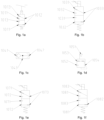
Fig. 1a is a schematic structural diagram of a changeover cock of a locomotive brake control system provided by an embodiment of the present application; -
Fig. 1b is a schematic structural diagram of a first solenoid valve of a locomotive brake control system provided by an embodiment of the present application; -
Fig. 1c is a schematic structural diagram of a two-way valve of a locomotive brake control system provided by an embodiment of the present application; -
Fig.1d is a schematic structural diagram of a brake cylinder relay valve of a locomotive brake control system provided by an embodiment of the present application; -
Fig. 1e is a schematic structural diagram of a second solenoid valve of a locomotive brake control system provided in an embodiment of the present application; -
Fig. 1f is a schematic structural diagram of a third solenoid valve of a locomotive brake control system provided in an embodiment of the present application; -
Fig. 1g is a schematic structural diagram of an brake cylinder equalizing pipe relay valve of a locomotive brake control system provided in an embodiment of the present application; -
Fig. 1h is a schematic structural diagram of a pneumatic control valve of a locomotive brake control system provided by an embodiment of the present application; -
Fig. 2 is a first schematic structural diagram of a locomotive brake control system provided by an embodiment of the present application, wherein the changeover cock is in the cut-in position; -
Fig. 3 is a second schematic structural diagram of a locomotive brake control system provided by an embodiment of the present application, wherein the changeover cock is in the cut-in position; -
Fig. 4 is a third schematic structural diagram of a locomotive brake control system provided by an embodiment of the present application, wherein the changeover cock is in the cut-off position; -
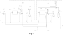
Fig. 5 is a fourth schematic structural diagram of a locomotive brake control system provided by an embodiment of the present application, wherein the changeover cock is in the cut-off position. - Wherein, the reference signs are as follows:
001, brake cylinder control system; 1, main reservoir pipe; 2, mechanical distribution valve pressure; 3, atmosphere; 5, brake cylinder pressure; 101, changeover cock; 1011, inlet port of changeover cock; 1012, outlet port of changeover cock; 1013, exhaust port of changeover cock; 102, brake cylinder pressure pre-control unit; 1021, inlet port of brake cylinder pressure pre-control unit; 1022, outlet port of brake cylinder pressure pre-control unit; 103, first solenoid valve; 1031, first inlet port of first solenoid valve; 1032, second inlet port of first solenoid valve; 1033, outlet port of first solenoid valve; 104, two-way valve; 1041, first inlet port of two-way valve; 1042, second inlet port of two-way valve; 1043, outlet port of two-way valve; 105, brake cylinder relay valve; 1051, pre-control port of brake cylinder relay valve; 1052, inlet port of brake cylinder relay valve; 1053, outlet port of brake cylinder relay valve; 1054, exhaust port of brake cylinder relay valve; 002, brake cylinder equalizing pipe control system; 106, brake cylinder equalizing pipe pressure pre-control unit; 1061, inlet port of brake cylinder equalizing pipe pressure pre-control unit; 1062, outlet port of brake cylinder equalizing pipe pressure pre-control unit; 107, second solenoid valve; 1071, first inlet port of second solenoid valve; 1072, second inlet port of second solenoid valve; 1073, outlet port of second solenoid valve; 108, third solenoid valve; 1081, inlet port of third solenoid valve ; 1082, outlet port of third solenoid valve; 1083, exhaust port of third solenoid valve; 109, brake cylinder equalizing pipe relay valve; 1091, pre-control port of brake cylinder equalizing pipe relay valve; 1092, inlet port of brake cylinder equalizing pipe relay valve; 1093, exhaust port of brake cylinder equalizing pipe relay valve; 1094, outlet port of brake cylinder equalizing pipe relay valve; 110, pneumatic control valve; 1101, inlet port of pneumatic control valve; 1102, pre-control port of pneumatic control valve; 1103, outlet port of pneumatic control valve; 8, brake cylinder equalizing pipe. - In order to make the purpose, technical solutions and advantages of the present application clearer, the present application will be described and illustrated below in conjunction with the accompanying drawings and embodiments. It should be understood that the specific embodiments described herein are only used to explain the present application and are not intended to limit the present application. Based on the embodiments provided in the present application, all other embodiments obtained by those of ordinary skill in the art without creative work are within the scope of protection of the present application.
- Apparently, the accompanying drawings in the following description are merely some of the examples or embodiments of the present application. For a person of ordinary skill in the art, without paying any creative effort, the present application can also be applied to other similar circumstances according to these accompanying drawings. In addition, it should also be understood that, although the effort made in the development process may be complicated and tedious, for a person of ordinary skill in the art related to the disclosure of the present application, some modifications in design, manufacture or production based on the technical contents disclosed by the present application are merely conventional technical means, and it should not be understood that the disclosure of the present application is insufficient.
- The term "embodiment" herein means that specific features, structures or characteristics described with reference to an embodiment can be comprised in at least one embodiment of the present application. The appearance of "embodiment" in various places of the description neither necessarily refers to the same embodiment, nor means an independent or alternative embodiment that is mutually exclusive with other embodiments. It should be explicitly and implicitly understood by those skilled in the art that an embodiment can be combined with other embodiments if not conflicted.
- Unless otherwise defined, the technical terms or scientific terms involved in the present application should have their ordinary meanings as understood by a person of ordinary skill in the technical field to which the present application pertains. Similar words such as "a", "an", "one" and "the" involved in the present application do not mean any quantity limitation, and may mean a singular or plural form. The terms such as "comprise", "comprise" and "have" and variants thereof involved in the present application are intended to cover non-exclusive inclusion. For example, a process, method, system, product or device comprising a series of steps or modules (units) is not limited to the listed steps or units, and may optionally comprise steps or units that are not listed or optionally comprise other steps or units intrinsic to this process, method, product or device. Similar words such as "connect", "link" and "couple" involved in the present application are not limited to physical or mechanical connection, and may comprise electrical connection, regardless of direct or indirect connection. The term "a plurality of" involved in the present application means two or more. The terms "first", "second", "third" and the like involved in the present application are merely for distinguishing similar objects, rather than indicating a specific order for the objects.
- The present application will be described in detail below in conjunction with the various embodiments shown in the accompanying drawings, but it should be noted that these embodiments are not limitations of the present application, and any equivalent transformations or substitutions in functions, methods, or structures made by a person of ordinary skill in the art based on these embodiments are all within the scope of protection of the present application.
- The trail unit is connected to the lead unit via a brake cylinder equalizing pipe, and the units are connected to the train via a brake pipe. In lead mode, which is an operational mode of the brake control system of the lead unit, the lead unit provides operational power and implements the brake control for the entire train. In this mode, the brake control system can control the pressure of the brake cylinder, the brake cylinder equalizing pipe and the brake pipe, thereby managing the brake and release of the lead unit, the trail unit and the train, respectively.
- Trail mode refers to an operational mode of the brake control system of the trail unit when two or more units are coupled. In this mode, the brake control system of the trail unit is controlled by the lead unit, and the brake cylinder of the trail unit responds to the brake and release control of the lead unit through the brake cylinder equalizing pipe.
- In the dead mode, the unit loses power and is connected to the train in a similar manner to a freight car. In this mode, the brake control system of the unpowered unit controls its own brake and release by responding to the brake pipe pressure of the lead unit.
-
Fig. 2 is a schematic structural diagram of the locomotive brake control system provided in the present application; as shown inFig. 2 , the locomotive brake control system comprises a brakecylinder control system 001, a brake cylinder equalizingpipe control system 002 and achangeover cock 101. - As shown in
Fig. 1a , thechangeover cock 101 is a two-position three-way valve, the two positions comprise a cut-in position and a cut-off position. When the locomotive brake control system is in the lead mode or the dead mode, thechangeover cock 101 is set to the cut-in position, and when the locomotive brake control system is in the trail mode, thechangeover cock 101 is set to the cut-off position. The three ways comprise aninlet port 1011 of the changeover cock, anoutlet port 1012 of the changeover cock, and anexhaust port 1013 of the changeover cock. When thechangeover cock 101 is in the cut-in position, theinlet port 1011 of the changeover cock is connected to theoutlet port 1012 of the changeover cock, and when thechangeover cock 101 is in the cut-off position, theoutlet port 1012 of the changeover cock is connected to theexhaust port 1013 of the changeover cock. Theinlet port 1011 of thechangeover cock 101 is connected to themain reservoir pipe 1, theoutlet port 1012 of the changeover cock is connected to the brake cylinder equalizingpipe control system 002, and theexhaust port 1013 of the changeover cock is connected to theatmosphere 3. - As shown in
Fig. 1b-Fig. 1h andFig. 2 , in some embodiments, the brakecylinder control system 001 comprises a brake cylinder pressurepre-control unit 102, afirst solenoid valve 103, a two-way valve 104 and a brakecylinder relay valve 105; the brake cylinder equalizingpipe control system 002 comprises a brake cylinder equalizing pipepressure pre-control unit 106, asecond solenoid valve 107, athird solenoid valve 108, a brake cylinder equalizingpipe relay valve 109 and apneumatic control valve 110. - An
inlet port 1021 of the brake cylinder pressure pre-control unit is connected to themain reservoir pipe 1, and anoutlet port 1022 of the brake cylinder pressure pre-control unit is connected to afirst inlet port 1031 of the first solenoid valve; asecond inlet port 1032 of the first solenoid valve is connected to mechanicaldistribution valve pressure 2, and anoutlet port 1033 of the first solenoid valve is connected to afirst inlet port 1041 of the two-way valve and asecond inlet port 1072 of the second solenoid valve; wherein, electronic distribution valve pressure output by the brake cylinder pressurepre-control unit 102 according to the change in the brake pipe pressure is the same as the mechanicaldistribution valve pressure 2. An outlet port 1043 of the two-way valve is connected to apre-control port 1051 of the brake cylinder relay valve, aninlet port 1052 of the brake cylinder relay valve is connected to themain reservoir pipe 1, anoutlet port 1053 of the brake cylinder relay valve is connected to a brake cylinder pipe, and anexhaust port 1054 of the brake cylinder relay valve is connected to theatmosphere 3. The mechanical distribution valve is connected to the brake pipe, and the mechanical distribution valve pressure, which is the pressure output by the mechanical distribution valve, is controlled by the brake pipe. When the brake pipe pressure decreases, the mechanical distribution valve pressure is increased; when the brake pipe pressure increases, the mechanical distribution valve pressure is decreased. The change in the brake pipe pressure is controlled by a brake pipe control device of the brake control system of the lead unit. The brake cylinder pressure is connected to the brake cylinder through the brake cylinder pipe. The logic program in the brake cylinder pressure pre-control unit controls the pressure output by the brake cylinder pressure pre-control unit to simulate the response relationship between the mechanical distribution valve pressure and the change in the brake pipe pressure. The brake cylinder pressure pre-control unit functions as an electronic distribution valve, and the pressure output by the brake cylinder pressure pre-control unit is the electronic distribution valve pressure. The logic program in the brake cylinder equalizing pipe pressure pre-control unit controls brake cylinder equalizing pipe pre-control pressure output by the brake cylinder equalizing pipe pressure pre-control unit to respond to the change in the brake pipe pressure. When the brake pipe pressure decreases, the brake cylinder equalizing pipe pre-control pressure is increased; when the brake pipe pressure increases, the brake cylinder equalizing pipe pre-control pressure is decreased. - An
inlet port 1061 of the brake cylinder equalizing pipe pressure pre-control unit is connected to theoutlet port 1012 of the changeover cock, anoutlet port 1062 of the brake cylinder equalizing pipe pressure pre-control unit is connected to afirst inlet port 1071 of the second solenoid valve, thesecond inlet port 1072 of the second solenoid valve is connected to theoutlet port 1033 of the first solenoid valve, anoutlet port 1073 of the second solenoid valve is connected to apre-control port 1091 of the brake cylinder equalizing pipe relay valve, aninlet port 1092 of the brake cylinder equalizing pipe relay valve is connected to themain reservoir pipe 1, anexhaust port 1093 of the brake cylinder equalizing pipe relay valve is connected to theatmosphere 3, and anoutlet port 1094 of the brake cylinder equalizing pipe relay valve is connected to aninlet port 1101 of the pneumatic control valve. - An
inlet port 1081 of the third solenoid valve is connected to theoutlet port 1012 of the changeover cock, anoutlet port 1082 of the third solenoid valve is connected to apre-control port 1102 of the pneumatic control valve, and anexhaust port 1083 of the third solenoid valve is connected to theatmosphere 3; theinlet port 1101 of the pneumatic control valve is connected to theoutlet port 1094 of the brake cylinder equalizing pipe relay valve, anoutlet port 1103 of the pneumatic control valve is connected to the brakecylinder equalizing pipe 8, and the brakecylinder equalizing pipe 8 is also connected to a second inlet port 1042 of the two-way valve. - In some embodiments, as shown in
Fig. 2 , when thechangeover cock 101 is in the cut-in position, if the locomotive brake control system is normal, the brakecylinder control system 001 outputs thebrake cylinder pressure 5 according to the electronic distribution valve pressure output by the brake cylinder pressurepre-control unit 102, and the brake cylinder equalizingpipe control system 002 outputs the brake cylinder equalizing pipe pressure according to the brake cylinder equalizing pipe pre-control pressure output by the brake cylinder equalizing pipepressure pre-control unit 106; if the locomotive brake control system is powered off or fails, the brake cylinder equalizingpipe control system 002 outputs the brake cylinder equalizing pipe pressure according to the mechanicaldistribution valve pressure 2, and the brakecylinder control system 001 outputs thebrake cylinder pressure 5 according to the mechanicaldistribution valve pressure 2 and the brake cylinder equalizing pipe pressure. When the locomotive brake control system is in the lead mode, the coordination between the brake cylinder equalizing pipe pressure and the brake cylinder pressure is realized, so as to achieve the consistency between the brake cylinder pressure of the trail unit and the brake cylinder pressure of the lead unit. - In some embodiments, as shown in
Fig. 2 , when thechangeover cock 101 is in the cut-in position, the locomotive brake control system is powered normally, and the brakecylinder control system 001 and the brake cylinder equalizingpipe control system 002 have no faults, thefirst solenoid valve 103 and thesecond solenoid valve 107 are energized, while thethird solenoid valve 108 is de-energized. When thefirst solenoid valve 103 is energized, thefirst inlet port 1031 of the first solenoid valve and theoutlet port 1033 of the first solenoid valve are connected; when thesecond solenoid valve 107 is energized, thefirst inlet port 1071 of the second solenoid valve and theoutlet port 1073 of the second solenoid valve are connected; when thethird solenoid valve 108 is de-energized, theinlet port 1081 of the third solenoid valve and theoutlet port 1082 of the third solenoid valve are connected. Themain reservoir pipe 1 provides main air pressure to the brake cylinder pressurepre-control unit 102, and the brake cylinder pressurepre-control unit 102 outputs the electronic distribution valve pressure according to the change in the brake pipe pressure. The electronic distribution valve pressure is input to the brakecylinder relay valve 105 after passing through thefirst solenoid valve 103 and the two-way valve 104. The brakecylinder relay valve 105 amplifies the flow of the electronic distribution valve pressure and outputs thebrake cylinder pressure 5. At the same time, the main air pressure from themain reservoir pipe 1 enters thepre-control port 1102 of the pneumatic control valve through thechangeover cock 101 and thethird solenoid valve 108, controlling thepneumatic control valve 110 to open. The brake cylinder equalizing pipepressure pre-control unit 106 receives the main air pressure of themain reservoir pipe 1 through thechangeover cock 101, and outputs the brake cylinder equalizing pipe pre-control pressure. The brake cylinder equalizing pipe pre-control pressure is input to the brake cylinder equalizingpipe relay valve 109 after passing through thesecond solenoid valve 107. The brake cylinder equalizing pipe pre-control pressure is amplified in flow by the brake cylinder equalizingpipe relay valve 109 and is input to thepneumatic control valve 110 to output the brake cylinder equalizing pipe pressure. - In some embodiments, as shown in
Fig. 3 , when thechangeover cock 101 is in the cut-in position, the locomotive brake control system is powered off or the brake cylinder control and the brake cylinder equalizing pipe control fail simultaneously (mainly due to abnormal power loss or network communication failure) or the locomotive brake control system is in the pneumatic position (also known as the backup brake mode) or the locomotive brake control system is in the dead mode, thefirst solenoid valve 103, thesecond solenoid valve 107, and thethird solenoid valve 108 are all de-energized. In this case, the mechanicaldistribution valve pressure 2 changes in response to the change in the brake pipe pressure. The mechanicaldistribution valve pressure 2 is input to thefirst inlet port 1041 of the two-way valve through thefirst solenoid valve 103. At the same time, the main air pressure from themain reservoir pipe 1 enters thepre-control port 1102 of the pneumatic control valve through thechangeover cock 101 and thethird solenoid valve 108, controlling thepneumatic control valve 110 to open. The mechanicaldistribution valve pressure 2 is also input to the brake cylinder equalizingpipe relay valve 109 through thefirst solenoid valve 103 and thesecond solenoid valve 107. The mechanicaldistribution valve pressure 2 is amplified in flow by the brake cylinder equalizingpipe relay valve 109 and is input to thepneumatic control valve 10 to output the brake cylinder equalizing pipe pressure. The brake cylinder equalizing pipe pressure enters the trail unit on the one hand, and is input to the second inlet port 1042 of the two-way valve through the brakecylinder equalizing pipe 8 on the other hand. The two-way valve 104 outputs pressure through the outlet port of two-way valve according to the mechanicaldistribution valve pressure 2 input through thefirst inlet port 1041 of the two-way valve and the brake cylinder equalizing pipe pressure input through the second inlet port 1042 of the two-way valve. The brakecylinder relay valve 105 amplifies the flow of the pressure output from the outlet port 1043 of the two-way valve and then outputs thebrake cylinder pressure 5. The pressure output from the outlet port of the is equal to the higher of the mechanical distribution valve pressure and the brake cylinder equalizing pipe pressure. Since the difference between the mechanical distribution valve pressure and the brake cylinder equalizing pipe pressure is small and within the allowable error range, it is generally considered that the mechanical distribution valve pressure is equal to the brake cylinder equalizing pipe pressure. If the locomotive brake control system is in the lead mode, the coordination between the brake cylinder equalizing pipe pressure and the brake cylinder pressure of the lead unit is achieved. If the locomotive brake control system is in the dead mode, the unpowered unit can respond to the brake pipe pressure of the lead unit to control its own brake and release without discharging the brake cylinder equalizing pipe pressure. - In some embodiments, as shown in
Fig. 4 , when thechangeover cock 101 is in the cut-off position, the locomotive brake control system is in the trail mode. If the locomotive brake control system is normal, the brakecylinder control system 001 outputs thebrake cylinder pressure 5 according to the brake cylinder equalizing pipe pressure from the lead unit; if the locomotive brake control system is powered off or fails, the brakecylinder control system 001 outputs thebrake cylinder pressure 5 according to the mechanicaldistribution valve pressure 2 and the brake cylinder equalizing pipe pressure from the lead unit. When the locomotive brake control system is in the trail mode, the locomotive brake control system controls the brake cylinder pressure of the trail unit to be coordinated with the brake cylinder equalizing pipe pressure. - In some embodiments, as shown in
Fig. 4 , when thechangeover cock 101 is in the cut-off position, the locomotive brake control system is in the trail mode, the locomotive brake control system is powered normally, and the brakecylinder control system 001 and the brake cylinder equalizingpipe control system 002 have no faults, in this case, thefirst solenoid valve 103, thesecond solenoid valve 107, and thethird solenoid valve 108 are energized; the brake cylinder pressurepre-control unit 102 controls the the electronic distribution valve pressure to decrease to 0 kPa, and the electronic distribution valve pressure enters thefirst inlet port 1041 of the two-way valve through thefirst solenoid valve 103; the brake cylinder equalizing pipepressure pre-control unit 106 controls the brake cylinder equalizing pipe pre-control pressure to decrease to 0 kPa, and pressure at thepre-control port 1102 of the pneumatic control valve is discharged to theatmosphere 3 through thethird solenoid valve 108 and thechangeover cock 101, so thepneumatic control valve 110 is in a closed state; the brake cylinder equalizing pipe pressure from the lead unit enters the second inlet port 1042 of the two-way valve through the brakecylinder equalizing pipe 8. Since the pressure at thefirst inlet port 1041 of the two-way valve is 0 kPa, the pressure at the second inlet port 1042 of the two-way valve enters thepre-control port 1051 of the brake cylinder relay valve, and after flow amplification of the brakecylinder relay valve 105, thebrake cylinder pressure 5 is output to the brake cylinder of the trail unit through theoutlet port 1053 of the brake cylinder relay valve. Therefore, the brake cylinder pressure of the trail unit can be coordinated with the brake cylinder equalizing pipe pressure from the lead unit. - In some embodiments, as shown in
Fig. 5 , when thechangeover cock 101 is in the cut-off position, the locomotive brake control system is in the trail mode, and the locomotive brake control system is powered off or the brakecylinder control system 001 and the brake cylinder equalizingpipe control system 002 fail simultaneously, in this case, thefirst solenoid valve 103, thesecond solenoid valve 107, and thethird solenoid valve 108 are de-energized, and the mechanicaldistribution valve pressure 2 changes in response to the change in the brake pipe pressure. The mechanicaldistribution valve pressure 2 enters thefirst inlet port 1041 of the two-way valve through thefirst solenoid valve 103 on the one hand, and enters thepre-control port 1091 of the brake cylinder equalizing pipe relay valve through thesecond solenoid valve 107 on the other hand. Since the pressure at thepre-control port 1102 of the pneumatic control valve is discharged to theatmosphere 3 through thethird solenoid valve 108 and thechangeover cock 101, thepneumatic control valve 110 is in a closed state, which can cut off the passage between the brake cylinder equalizingpipe relay valve 109 and the brakecylinder equalizing pipe 8. The brake cylinder equalizing pipe pressure from the lead unit enters the second inlet port 1042 of the two-way valve through the brakecylinder equalizing pipe 8, and the two-way valve 104 outputs pressure through the outlet port of the two-way valve, which is equal to the higher of the mechanical distribution valve pressure and the brake cylinder equalizing pipe pressure. Since the difference between the mechanical distribution valve pressure and the brake cylinder equalizing pipe pressure is small and within the allowable error range, it is generally believed that the mechanical distribution valve pressure is equal to the brake cylinder equalizing pipe pressure. Since the mechanicaldistribution valve pressure 2 is consistent with the brake cylinder equalizing pipe pressure of the lead unit, the pressure output from the outlet port 1043 of the two-way valve enters thepre-control port 1051 of the brake cylinder relay valve, and the brake cylinder pressure of the trail unit is output after flow amplification, so that the brake cylinder pressure of the trail unit can be coordinated with the brake cylinder equalizing pipe pressure from the lead unit. - In combination with the locomotive brake control system disclosed in the first embodiment, the present embodiment discloses a specific implementation example of a locomotive brake control method (hereinafter referred to as "method") applied to the above locomotive brake control system.
- The locomotive brake control method comprises:
- when the locomotive brake control system is in the lead mode, the
changeover cock 101 is set to the cut-in position, if the locomotive brake control system is normal, the brakecylinder control system 001 in the locomotive brake control system outputs thebrake cylinder pressure 5 according to the electronic distribution valve pressure, and the brake cylinder equalizingpipe control system 002 outputs the brake cylinder equalizing pipe pressure according to the brake cylinder equalizing pipe pre-control pressure; if the locomotive brake control system is powered off or fails, the brake cylinder equalizingpipe control system 002 outputs the brake cylinder equalizing pipe pressure according to the mechanicaldistribution valve pressure 2, and the brakecylinder control system 001 outputs thebrake cylinder pressure 5 according to the mechanicaldistribution valve pressure 2 and the brake cylinder equalizing pipe pressure; - when the locomotive brake control system is in the dead mode, the
changeover cock 101 is set to the cut-in position, the brake cylinder equalizingpipe control system 002 outputs the brake cylinder equalizing pipe pressure according to the mechanicaldistribution valve pressure 2, and the brakecylinder control system 001 outputs thebrake cylinder pressure 5 according to the mechanicaldistribution valve pressure 2 and the brake cylinder equalizing pipe pressure; - when the locomotive brake control system is in the trail mode, the
changeover cock 101 is set to the cut-off position, if the locomotive brake control system is normal, the brakecylinder control system 001 controls the electronic distribution valve pressure to decrease to 0 kPa, and outputs thebrake cylinder pressure 5 according to the brake cylinder equalizing pipe pressure from the lead unit; if the locomotive brake control system is powered off or fails, the brakecylinder control system 001 outputs thebrake cylinder pressure 5 according to the mechanicaldistribution valve pressure 2 and the brake cylinder equalizing pipe pressure from the lead unit. - Specifically, when the locomotive brake control system is in the lead mode and the system is normal, that is, the power supply is normal, and the brake cylinder control and the brake cylinder equalizing pipe control have no faults, the system energizes the
first solenoid valve 103 and thesecond solenoid valve 107, and de-energizes thethird solenoid valve 108. Thechangeover cock 101 needs to be manually set to the cut-in position in the lead mode. The brake cylinder pressurepre-control unit 102 outputs the electronic distribution valve pressure according to the change in the brake pipe pressure, and thebrake cylinder pressure 5 is output after flow amplification of the brakecylinder relay valve 105. At the same time, the main air pressure from themain reservoir pipe 1 enters the pre-control port of thepneumatic control valve 110 through thechangeover cock 101, controls thepneumatic control valve 110 to open, and the brake cylinder equalizing pipe pre-control pressure output by the brake cylinder equalizing pipepressure pre-control unit 106 is amplified in flow by the brake cylinder equalizingpipe relay valve 109 and is input to thepneumatic control valve 110 to output the brake cylinder equalizing pipe pressure. - When the locomotive brake control system is in the lead mode and the locomotive brake control system is powered off or the locomotive brake control system is in the pneumatic position or the brake cylinder control and the brake cylinder equalizing pipe control of the locomotive brake control system fail at the same time (mainly due to abnormal power loss or network communication failure), or the locomotive brake control system is in the dead mode, the
changeover cock 101 is set to the cut-in position, thefirst solenoid valve 103, thesecond solenoid valve 107 and thethird solenoid valve 108 are all de-energized, and the mechanicaldistribution valve pressure 2 changes in response to the change in the brake pipe pressure and enters thefirst inlet port 1041 of the two-way valve. At the same time, the main air pressure from themain reservoir pipe 1 enters thepre-control port 1102 of the pneumatic control valve through thechangeover cock 101, controls thepneumatic control valve 110 to open. The mechanicaldistribution valve pressure 2 is amplified in flow by the brake cylinder equalizingpipe relay valve 109 and is input to thepneumatic control valve 110 to output the brake cylinder equalizing pipe pressure. The brake cylinder equalizing pipe pressure enters the trail unit on the one hand, and enters the second inlet port 1042 of the two-way valve on the other hand. The pressure at thefirst inlet port 1041 of the two-way valve and the pressure at the second inlet port 1042 of the two-way valve are equal. The pressure output from the outlet port 1043 of the two-way valve is amplified in flow by the brakecylinder relay valve 105 to output thebrake cylinder pressure 5, achieving the coordination between the brake cylinder equalizing pipe pressure and the brake cylinder pressure. Under the premise of not changing the existing design of the locomotive and not increasing the complexity of the brake control system, for example, additional valves and related control devices for supplying air from the brake cylinder to the brake cylinder equalizing pipe are not needed, the coordination between the brake cylinder equalizing pipe pressure and the brake cylinder pressure of the lead unit is achieved. In the non-powered return mode, there is no need to exhaust the brake cylinder equalizing pipe pressure. - When the locomotive brake control system is in the trail mode and the system is normal (power supply is normal, and the brake cylinder control and the brake cylinder equalizing pipe control have no faults), the
changeover cock 101 is set to the cut-off position, thefirst solenoid valve 103, thesecond solenoid valve 107, and thethird solenoid valve 108 are all energized, and the brake cylinder pressurepre-control unit 102 controls the electronic distribution valve pressure to decrease to 0 kPa, and the electronic distribution valve pressure enters thefirst inlet port 1041 of the two-way valve. The brake cylinder equalizing pipepressure pre-control unit 106 controls the brake cylinder equalizing pipe pre-control pressure to decrease to OkPa, and pressure at thepre-control port 1102 of the pneumatic control valve is discharged to theatmosphere 3 through thechangeover cock 101, so thepneumatic control valve 110 is in a closed state, and the brake cylinder equalizing pipe pressure from the lead unit enters the second inlet port 1042 of the two-way valve. Since the pressure at thefirst inlet port 1041 of the two-way valve is OkPa, the pressure at the second inlet port 1042 of the two-way valve enters thepre-control port 1051 of the brake cylinder relay valve, and after flow amplification of the brakecylinder relay valve 105, the brake cylinder pressure is output to the brake cylinder of the trail unit, so that the brake cylinder pressure of the trail unit can be coordinated with the brake cylinder equalizing pipe pressure from the lead unit. - When the locomotive brake control system is in the trail mode and the brake control system is powered off or the brake cylinder control and the brake cylinder equalizing pipe control fail simultaneously, the
changeover cock 101 is set to the cut-off position, thefirst solenoid valve 103, thesecond solenoid valve 107, and thethird solenoid valve 108 are all de-energized, and the mechanicaldistribution valve pressure 2 changes in response to the change in the brake pipe pressure. The mechanicaldistribution valve pressure 2 enters thefirst inlet port 1041 of the two-way valve on the one hand, and enters thepre-control port 1091 of the brake cylinder equalizing pipe relay valve on the other hand. Since the pressure at thepre-control port 1102 of the pneumatic control valve is discharged to theatmosphere 3 through thechangeover cock 101, thepneumatic control valve 110 is in a closed state, which can cut off the passage between the brake cylinder equalizingpipe relay valve 109 and the brake cylinder equalizing pipe. The brake cylinder equalizing pipe pressure from the lead unit enters the second inlet port 1042 of the two-way valve. Since the mechanicaldistribution valve pressure 2 is consistent with the brake cylinder equalizing pipe pressure of the lead unit, the pressure output from the outlet port 1043 of the two-way valve enters thepre-control port 1051 of the brake cylinder relay valve, and outputs the brake cylinder pressure of the trail unit after flow amplification. Therefore, the brake cylinder pressure of the trail unit can be coordinated with the brake cylinder equalizing pipe pressure from the lead unit. - To summarize, in the lead mode, when the brake control system is powered off, the brake control system is in the pneumatic position, or the brake cylinder control and the brake cylinder equalizing pipe control fail simultaneously, the coordination between the brake cylinder equalizing pipe pressure and the brake cylinder pressure of the lead unit is achieved; in the trail mode, when the brake control system is powered off or the brake cylinder control and the brake cylinder equalizing pipe control fail simultaneously, the coordination between the brake cylinder pressure of the trail unit and the brake cylinder equalizing pipe pressure is achieved; in the dead mode, there is no need to discharge the brake cylinder equalizing pipe pressure. Under the above-mentioned special conditions, the present application improves the consistency of brake and release between the lead unit and the trail unit, enhances the stability of train operation, reduces operation steps required for the dead mode, and is conducive to use and maintenance.
- The technical features of the above-described embodiments may be arbitrarily combined. To make the description concise, not all possible combinations of the technical features in the above-described embodiments are described. However, as long as there is no contradiction in the combination of these technical features, they should be considered to be within the scope of this specification.
- The above-described embodiments represent only several implementations of the present application, and the descriptions thereof are relatively specific and detailed, but should not be understood as limiting the scope of the present application. It should be noted that, for a person of ordinary skill in the art, various modifications and improvements can be made without departing from the concept of the present application, and such modifications and improvements fall within the scope of protection of the present application. Therefore, the protection scope of the present application shall be subject to the appended claims.
Claims (15)
- A locomotive brake control system, comprising: a brake cylinder control system, a brake cylinder equalizing pipe control system and a changeover cock;when the changeover cock is in a cut-in position, if the locomotive brake control system is normal, the brake cylinder control system outputs brake cylinder pressure according to electronic distribution valve pressure, and the brake cylinder equalizing pipe control system outputs brake cylinder equalizing pipe pressure according to brake cylinder equalizing pipe pre-control pressure; if the locomotive brake control system is powered off or fails, the brake cylinder equalizing pipe control system outputs the brake cylinder equalizing pipe pressure according to mechanical distribution valve pressure, and the brake cylinder control system outputs the brake cylinder pressure according to the mechanical distribution valve pressure and the brake cylinder equalizing pipe pressure;when the changeover cock is in a cut-in position, if the locomotive brake control system is in a dead mode, the brake cylinder equalizing pipe control system outputs the brake cylinder equalizing pipe pressure according to the mechanical distribution valve pressure, and the brake cylinder control system outputs the brake cylinder pressure according to the mechanical distribution valve pressure and the brake cylinder equalizing pipe pressure;when the changeover cock is in a cut-off position, if the locomotive brake control system is normal, the brake cylinder control system outputs the brake cylinder pressure according to the electronic distribution valve pressure and the brake cylinder equalizing pipe pressure from a lead unit; if the locomotive brake control system is powered off or fails, the brake cylinder control system outputs the brake cylinder pressure according to the mechanical distribution valve pressure and the brake cylinder equalizing pipe pressure from the lead unit.
- The locomotive brake control system according to claim 1, characterized in that, the changeover cock is a two-position three-way valve, when the changeover cock is in the cut-in position, an inlet port of the changeover cock is connected to an outlet port of the changeover cock, and when the changeover cock is in the cut-off position, the outlet port of the changeover cock is connected to an exhaust port of the changeover cock; the inlet port of the changeover cock is connected to a main reservoir pipe, the outlet port of the changeover cock is connected to the brake cylinder equalizing pipe control system, and the exhaust port of the changeover cock is connected to atmosphere.
- The locomotive brake control system according to claim 2, characterized in that, the brake cylinder control system comprises a brake cylinder pressure pre-control unit, a first solenoid valve, a two-way valve and a brake cylinder relay valve; an inlet port of the brake cylinder pressure pre-control unit is connected to the main reservoir pipe, and an outlet port of the brake cylinder pressure pre-control unit is connected to a first inlet port of the first solenoid valve; a second inlet port of the first solenoid valve is connected to the mechanical distribution valve pressure, and an outlet port of the first solenoid valve is connected to a first inlet port of the two-way valve; an outlet port of the two-way valve is connected to a pre-control port of the brake cylinder relay valve, an inlet port of the brake cylinder relay valve is connected to the main reservoir pipe, an outlet port of the brake cylinder relay valve is connected to a brake cylinder pipe, and an exhaust port of the brake cylinder relay valve is connected to the atmosphere.
- The locomotive brake control system according to claim 3, characterized in that, the brake cylinder equalizing pipe control system comprises a brake cylinder equalizing pipe pressure pre-control unit, a second solenoid valve and a brake cylinder equalizing pipe relay valve; an inlet port of the brake cylinder equalizing pipe pressure pre-control unit is connected to the outlet port of the changeover cock, an outlet port of the brake cylinder equalizing pipe pressure pre-control unit is connected to a first inlet port of the second solenoid valve, a second inlet port of the second solenoid valve is connected to the outlet port of the first solenoid valve, an outlet port of the second solenoid valve is connected to a pre-control port of the brake cylinder equalizing pipe relay valve, an inlet port of the brake cylinder equalizing pipe relay valve is connected to the main reservoir pipe, an exhaust port of the brake cylinder equalizing pipe relay valve is connected to the atmosphere.
- The locomotive brake control system according to claim 4, characterized in that, the brake cylinder equalizing pipe control system also comprises a third solenoid valve and a pneumatic control valve; an inlet port of the third solenoid valve is connected to the outlet port of the changeover cock, an outlet port of the third solenoid valve is connected to a pre-control port of the pneumatic control valve; an inlet port of the pneumatic control valve is connected to an outlet port of the brake cylinder equalizing pipe relay valve, an outlet port of the pneumatic control valve is connected to a brake cylinder equalizing pipe, and the brake cylinder equalizing pipe is connected to a second inlet port of the two-way valve.
- The locomotive brake control system according to claim 5, characterized in that, when the first solenoid valve and the second solenoid valve are energized, the third solenoid valve is de-energized, and the changeover cock is set to the cut-in position, the main reservoir pipe provides main air pressure to the brake cylinder pressure pre-control unit, and the brake cylinder pressure pre-control unit outputs the electronic distribution valve pressure according to change in brake pipe pressure; the electronic distribution valve pressure is input to the brake cylinder relay valve after passing through the first solenoid valve and the two-way valve, the brake cylinder relay valve amplifies flow of the electronic distribution valve pressure and outputs the brake cylinder pressure; at the same time, the main air pressure from the main reservoir pipe enters the pre-control port of the pneumatic control valve through the changeover cock and the third solenoid valve, and controls the pneumatic control valve to open; the brake cylinder equalizing pipe pressure pre-control unit receives the main air pressure from the main reservoir pipe through the changeover cock, and outputs the brake cylinder equalizing pipe pre-control pressure, the brake cylinder equalizing pipe pre-control pressure is input to the brake cylinder equalizing pipe relay valve after passing through the second solenoid valve, the brake cylinder equalizing pipe pre-control pressure is amplified in flow by the brake cylinder equalizing pipe relay valve and is input to the pneumatic control valve to output the brake cylinder equalizing pipe pressure.
- The locomotive brake control system according to claim 5, characterized in that, when the first solenoid valve, the second solenoid valve and the third solenoid valve are all de-energized and the changeover cock is set to the cut-in position, the mechanical distribution valve pressure is input to the first inlet port of the two-way valve through the first solenoid valve, and is also input to the brake cylinder equalizing pipe relay valve through the first solenoid valve and the second solenoid valve; main air pressure from the main reservoir pipe enters the pre-control port of the pneumatic control valve through the changeover cock and the third solenoid valve, and controls the pneumatic control valve to open; the mechanical distribution valve pressure is amplified in flow by the brake cylinder equalizing pipe relay valve and is input to the pneumatic control valve to output the brake cylinder equalizing pipe pressure, the brake cylinder equalizing pipe pressure is input to the second inlet port of the two-way valve through the brake cylinder equalizing pipe; the two-way valve outputs pressure through the outlet port of the two-way valve according to the mechanical distribution valve pressure input through the first inlet port of the two-way valve and the brake cylinder equalizing pipe pressure input through the second inlet port of the two-way valve, the brake cylinder relay valve amplifies flow of the pressure output from the outlet port of the two-way valve and then outputs the brake cylinder pressure.
- The locomotive brake control system according to claim 5, characterized in that, when the first solenoid valve, the second solenoid valve and the third solenoid valve are all energized and the changeover cock is set to the cut-off position, the brake cylinder equalizing pipe pressure from the lead unit is input to the pre-control port of the brake cylinder relay valve through the brake cylinder equalizing pipe via the second inlet port of the two-way valve, and the brake cylinder relay valve amplifies flow of the brake cylinder equalizing pipe pressure and then outputs the brake cylinder pressure.
- The locomotive brake control system according to claim 5, characterized in that, when the first solenoid valve, the second solenoid valve and the third solenoid valve all de-energized and the changeover cock is set to the cut-off position, the mechanical distribution valve pressure is input to the first inlet port of the two-way valve through the first solenoid valve, the brake cylinder equalizing pipe pressure from the lead unit is input to the second inlet port of the two-way valve through the brake cylinder equalizing pipe, and the two-way valve outputs pressure through the outlet port of the two-way valve according to the mechanical distribution valve pressure input through the first inlet port of the two-way valve and the brake cylinder equalizing pipe pressure input through the second inlet port of the two-way valve, and the brake cylinder relay valve amplifies flow of the pressure output from the outlet port of the two-way valve and then outputs the brake cylinder pressure.
- A locomotive brake control method, which is applied to the locomotive brake control system according to any one of claims 1-9, comprising:when the locomotive brake control system is in a lead mode, setting the changeover cock to the cut-in position, if the locomotive brake control system is normal, the brake cylinder control system in the locomotive brake control system outputs the brake cylinder pressure according to the electronic distribution valve pressure, and the brake cylinder equalizing pipe control system outputs the brake cylinder equalizing pipe pressure according to the brake cylinder equalizing pipe pre-control pressure; if the locomotive brake control system is powered off or fails, the brake cylinder equalizing pipe control system outputs the brake cylinder equalizing pipe pressure according to the mechanical distribution valve pressure, and the brake cylinder control system outputs the brake cylinder pressure according to the mechanical distribution valve pressure and the brake cylinder equalizing pipe pressure;when the locomotive brake control system is in the dead mode, setting the changeover cock to the cut-in position, the brake cylinder equalizing pipe control system outputs the brake cylinder equalizing pipe pressure according to the mechanical distribution valve pressure, and the brake cylinder control system outputs the brake cylinder pressure according to the mechanical distribution valve pressure and the brake cylinder equalizing pipe pressure;when the locomotive brake control system is in a trail mode, setting the changeover cock to the cut-off position, if the locomotive brake control system is normal, the brake cylinder control system controls the electronic distribution valve pressure to decrease to 0 kPa, and the brake cylinder control system outputs the brake cylinder pressure according to the brake cylinder equalizing pipe pressure from the lead unit; if the locomotive brake control system is powered off or fails, the brake cylinder control system outputs the brake cylinder pressure according to the mechanical distribution valve pressure and the brake cylinder equalizing pipe pressure from the lead unit.
- The locomotive brake control method according to claim 10, characterized in that:
when the locomotive brake control system is in the lead mode, setting the changeover cock to the cut-in position, if the locomotive brake control system is normal, the first solenoid valve and the second solenoid valve are energized, and the third solenoid valve is de-energized, the brake cylinder pressure pre-control unit outputs the electronic distribution valve pressure according to change in brake pipe pressure, and the electronic distribution valve pressure is amplified in flow by the brake cylinder relay valve to output the brake cylinder pressure; at the same time, main air pressure from a main reservoir pipe enters a pre-control port of the pneumatic control valve through the changeover cock, and controls the pneumatic control valve to open, the brake cylinder equalizing pipe pre-control pressure output by the brake cylinder equalizing pipe pressure pre-control unit is amplified in flow by the brake cylinder equalizing pipe relay valve and is input to the pneumatic control valve to output the brake cylinder equalizing pipe pressure. - The locomotive brake control method according to claim 11, characterized in that:
when the locomotive brake control system is in the lead mode, setting the changeover cock to the cut-in position, if the locomotive brake control system is powered off or fails, the first solenoid valve, the second solenoid valve and the third solenoid valve are all de-energized, and the mechanical distribution valve pressure changes in response to change in brake pipe pressure and enters a first inlet port of the two-way valve; at the same time, the main air pressure from the main reservoir pipe enters a pre-control port of the pneumatic control valve through the changeover cock, and controls the pneumatic control valve to open; the mechanical distribution valve pressure is amplified in flow by the brake cylinder equalizing pipe relay valve and is input to the pneumatic control valve to output the brake cylinder equalizing pipe pressure; the brake cylinder equalizing pipe pressure enters a trail unit on the one hand, and enters a second inlet port of the two-way valve on the other hand; pressure output from an outlet port of the two-way valve is amplified in flow by the brake cylinder relay valve to output the brake cylinder pressure. - The locomotive brake control method according to claim 10, characterized in that, when the locomotive brake control system is in the dead mode, setting the changeover cock to the cut-in position, the first solenoid valve, the second solenoid valve and the third solenoid valve are all de-energized, and the mechanical distribution valve pressure changes in response to change in brake pipe pressure and enters a first inlet port of the two-way valve; at the same time, main air pressure from the main reservoir pipe enters a pre-control port of the pneumatic control valve through the changeover cock, and controls the pneumatic control valve to open; the mechanical distribution valve pressure is amplified in flow by the brake cylinder equalizing pipe relay valve and is input to the pneumatic control valve to output the brake cylinder equalizing pipe pressure; the brake cylinder equalizing pipe pressure enters a trail unit on the one hand, and enters a second inlet port of the two-way valve on the other hand; pressure output from the outlet port of the two-way valve is amplified in flow by the brake cylinder relay valve to output the brake cylinder pressure.
- The locomotive brake control method according to claim 10, characterized in that, when the locomotive brake control system is in the trail mode, setting the changeover cock to the cut-off position, if the locomotive brake control system is normal, the first solenoid valve, the second solenoid valve, and the third solenoid valve are all energized, and the brake cylinder pressure pre-control unit controls the electronic distribution valve pressure to decrease to OkPa, and the electronic distribution valve pressure enters a first inlet port of the two-way valve; the brake cylinder equalizing pipe pressure pre-control unit controls the brake cylinder equalizing pipe pre-control pressure to decrease to OkPa; pressure at the pre-control port of the pneumatic control valve is discharged to the atmosphere through the changeover cock, and the pneumatic control valve is in a closed state; the brake cylinder equalizing pipe pressure from the lead unit enters a second inlet port of the two-way valve, pressure at the second inlet port of the two-way valve enters a pre-control port of the brake cylinder relay valve, and the brake cylinder pressure is output to the brake cylinder of the trail unit after flow amplification of the brake cylinder relay valve.
- The locomotive brake control method according to claim 14, characterized in that, when the locomotive brake control system is in the trail mode, setting the changeover cock to the cut-off position, if the locomotive brake control system is powered off or fails, the first solenoid valve, the second solenoid valve, and the third solenoid valve are all de-energized, and the mechanical distribution valve pressure changes in response to change in the brake pipe pressure; the mechanical distribution valve pressure enters the first inlet port of the two-way valve on the one hand, and enters a pre-control port of the brake cylinder equalizing pipe relay valve on the other hand; pressure at the pre-control port of the pneumatic control valve is discharged to the atmosphere through the changeover cock, and the pneumatic control valve is in a closed state; the brake cylinder equalizing pipe pressure from the lead unit enters the second inlet port of the two-way valve, pressure output from the outlet port of the two-way valve enters the pre-control port of the brake cylinder relay valve, and the brake cylinder pressure of the trail unit is output after flow amplification.
Applications Claiming Priority (2)
| Application Number | Priority Date | Filing Date | Title |
|---|---|---|---|
| CN202210596432.8A CN114750737B (en) | 2022-05-30 | 2022-05-30 | Locomotive brake control system and control method |
| PCT/CN2022/131670 WO2023046215A1 (en) | 2022-05-30 | 2022-11-14 | Locomotive brake control system and control method |
Publications (3)
| Publication Number | Publication Date |
|---|---|
| EP4497652A1 true EP4497652A1 (en) | 2025-01-29 |
| EP4497652A4 EP4497652A4 (en) | 2025-07-02 |
| EP4497652B1 EP4497652B1 (en) | 2026-04-08 |
Family
ID=82336316
Family Applications (1)
| Application Number | Title | Priority Date | Filing Date |
|---|---|---|---|
| EP22872258.3A Active EP4497652B1 (en) | 2022-05-30 | 2022-11-14 | Locomotive brake control system and control method |
Country Status (3)
| Country | Link |
|---|---|
| EP (1) | EP4497652B1 (en) |
| CN (1) | CN114750737B (en) |
| WO (1) | WO2023046215A1 (en) |
Families Citing this family (3)
| Publication number | Priority date | Publication date | Assignee | Title |
|---|---|---|---|---|
| CN114750737B (en) * | 2022-05-30 | 2023-01-20 | 中车制动系统有限公司 | Locomotive brake control system and control method |
| CN116252766A (en) * | 2023-04-23 | 2023-06-13 | 北京中车长客二七轨道装备有限公司 | Wheel disc hydraulic braking system and maglev train |
| CN116811819B (en) * | 2023-07-24 | 2026-02-10 | 中车制动系统有限公司 | Locomotive Braking Control System and Control Method |
Family Cites Families (9)
| Publication number | Priority date | Publication date | Assignee | Title |
|---|---|---|---|---|
| US4755803A (en) * | 1987-05-27 | 1988-07-05 | Pulse Electronics, Inc. | Air brake manifold all level reset |
| CN103043076A (en) * | 2012-12-24 | 2013-04-17 | 青岛四方车辆研究所有限公司 | Relay valve for brake system of railway vehicle |
| CN104442903B (en) * | 2014-11-07 | 2017-01-18 | 南车株洲电力机车有限公司 | Control method and device for locomotive brake average tube |
| US10315637B2 (en) * | 2017-03-20 | 2019-06-11 | Westinghouse Air Brake Technologies Corporation | Automatic brake backup control system and method |
| CN111634304B (en) * | 2019-03-01 | 2021-02-19 | 中车青岛四方车辆研究所有限公司 | A locomotive brake control system and control method |
| CN110065521B (en) * | 2019-05-17 | 2020-04-28 | 中车青岛四方车辆研究所有限公司 | Locomotive brake control system and method |
| CN111661025B (en) | 2020-06-18 | 2021-06-04 | 中车株洲电力机车有限公司 | A method and device for controlling the average pipe pressure of a locomotive brake |
| CN113002584B (en) * | 2021-03-31 | 2022-06-03 | 中车青岛四方车辆研究所有限公司 | Locomotive brake cylinder and mean pipe pressure control system and control method |
| CN114750737B (en) * | 2022-05-30 | 2023-01-20 | 中车制动系统有限公司 | Locomotive brake control system and control method |
-
2022
- 2022-05-30 CN CN202210596432.8A patent/CN114750737B/en active Active
- 2022-11-14 EP EP22872258.3A patent/EP4497652B1/en active Active
- 2022-11-14 WO PCT/CN2022/131670 patent/WO2023046215A1/en not_active Ceased
Also Published As
| Publication number | Publication date |
|---|---|
| EP4497652A4 (en) | 2025-07-02 |
| EP4497652B1 (en) | 2026-04-08 |
| WO2023046215A1 (en) | 2023-03-30 |
| CN114750737A (en) | 2022-07-15 |
| CN114750737B (en) | 2023-01-20 |
Similar Documents
| Publication | Publication Date | Title |
|---|---|---|
| EP4497652A1 (en) | Locomotive brake control system and control method | |
| EP3828054B1 (en) | Electric-air brake | |
| CN105383473B (en) | air brake valve for locomotive | |
| EP3636504B1 (en) | A system for controlling backup air brake for a locomotive | |
| CN201761483U (en) | Brake system for railroad locomotive | |
| CN109353369B (en) | Rail vehicle rescue braking system and control method | |
| WO2020233648A1 (en) | Rail train braking system | |
| CN101941382A (en) | Railway wagon electropneumatic brake system and method based on wireless communication | |
| CN113060177A (en) | Locomotive brake cylinder control system and control method | |
| ZA200503792B (en) | Interface system for pneumatic to electrically-controlled pneumatic brake systems | |
| CN105564402A (en) | Intelligent control module for locomotive brake train pipe | |
| CN116811819A (en) | Locomotive braking control system and control method | |
| CN115009246B (en) | Microcomputer controlled air brake device adapted to existing rail engineering vehicle brake system | |
| US7240970B2 (en) | Trail locomotive brake control | |
| CN103863352A (en) | Automatic control system for car coupler and application thereof | |
| CN205149845U (en) | Machine vehicle air brake valve | |
| CN203819258U (en) | Automatic control system for car coupler | |
| WO2024120044A1 (en) | Braking system for automatic switching between train pipe control and microcomputer control and method | |
| CN217455946U (en) | Remote control brake integrated valve plate module for railway vehicle | |
| CN111661025B (en) | A method and device for controlling the average pipe pressure of a locomotive brake | |
| CN211918639U (en) | Load adjusting module and train brake control system | |
| CN115675563A (en) | Unpowered loopback control system adaptive to motor train unit and locomotive and vehicle thereof | |
| CN114954556A (en) | Brake integrated valve plate module for unmanned driving | |
| CN111775999B (en) | Train pipe quantitative pressure reduction control system and method | |
| WO2025260737A1 (en) | Rail transit vehicle, automatic lead/trail switching device for locomotive brakes, and method |
Legal Events
| Date | Code | Title | Description |
|---|---|---|---|
| STAA | Information on the status of an ep patent application or granted ep patent |
Free format text: STATUS: THE INTERNATIONAL PUBLICATION HAS BEEN MADE |
|
| PUAI | Public reference made under article 153(3) epc to a published international application that has entered the european phase |
Free format text: ORIGINAL CODE: 0009012 |
|
| STAA | Information on the status of an ep patent application or granted ep patent |
Free format text: STATUS: REQUEST FOR EXAMINATION WAS MADE |
|
| 17P | Request for examination filed |
Effective date: 20241022 |
|
| AK | Designated contracting states |
Kind code of ref document: A1 Designated state(s): AL AT BE BG CH CY CZ DE DK EE ES FI FR GB GR HR HU IE IS IT LI LT LU LV MC ME MK MT NL NO PL PT RO RS SE SI SK SM TR |
|
| REG | Reference to a national code |
Ref country code: DE Ref legal event code: R079 Free format text: PREVIOUS MAIN CLASS: B61H0011060000 Ipc: B60T0013660000 Ref document number: 602022034313 Country of ref document: DE |
|
| A4 | Supplementary search report drawn up and despatched |
Effective date: 20250604 |
|
| RIC1 | Information provided on ipc code assigned before grant |
Ipc: B61H 13/00 20060101ALI20250528BHEP Ipc: B60T 13/40 20060101ALI20250528BHEP Ipc: B60T 8/17 20060101ALI20250528BHEP Ipc: B60T 17/22 20060101ALI20250528BHEP Ipc: B60T 13/68 20060101ALI20250528BHEP Ipc: B60T 13/66 20060101AFI20250528BHEP |
|
| DAV | Request for validation of the european patent (deleted) | ||
| DAX | Request for extension of the european patent (deleted) | ||
| GRAP | Despatch of communication of intention to grant a patent |
Free format text: ORIGINAL CODE: EPIDOSNIGR1 |
|
| STAA | Information on the status of an ep patent application or granted ep patent |
Free format text: STATUS: GRANT OF PATENT IS INTENDED |
|
| RIC1 | Information provided on ipc code assigned before grant |
Ipc: B60T 13/66 20060101AFI20251016BHEP Ipc: B60T 13/68 20060101ALI20251016BHEP Ipc: B60T 17/22 20060101ALI20251016BHEP Ipc: B60T 8/17 20060101ALI20251016BHEP Ipc: B60T 13/40 20060101ALI20251016BHEP Ipc: B61H 13/00 20060101ALI20251016BHEP Ipc: B60T 15/02 20060101ALI20251016BHEP Ipc: B61H 13/20 20060101ALI20251016BHEP |
|
| INTG | Intention to grant announced |
Effective date: 20251106 |
|
| GRAS | Grant fee paid |
Free format text: ORIGINAL CODE: EPIDOSNIGR3 |
|
| GRAA | (expected) grant |
Free format text: ORIGINAL CODE: 0009210 |
|
| STAA | Information on the status of an ep patent application or granted ep patent |
Free format text: STATUS: THE PATENT HAS BEEN GRANTED |
|
| AK | Designated contracting states |
Kind code of ref document: B1 Designated state(s): AL AT BE BG CH CY CZ DE DK EE ES FI FR GB GR HR HU IE IS IT LI LT LU LV MC ME MK MT NL NO PL PT RO RS SE SI SK SM TR |
|
| REG | Reference to a national code |
Ref country code: CH Ref legal event code: F10 Free format text: ST27 STATUS EVENT CODE: U-0-0-F10-F00 (AS PROVIDED BY THE NATIONAL OFFICE) Effective date: 20260408 Ref country code: GB Ref legal event code: FG4D |
|
| REG | Reference to a national code |
Ref country code: DE Ref legal event code: R096 Ref document number: 602022034313 Country of ref document: DE |