EP4497633A1 - Vehicular lamp system, light distribution control device, and light distribution control method - Google Patents
Vehicular lamp system, light distribution control device, and light distribution control method Download PDFInfo
- Publication number
- EP4497633A1 EP4497633A1 EP23774414.9A EP23774414A EP4497633A1 EP 4497633 A1 EP4497633 A1 EP 4497633A1 EP 23774414 A EP23774414 A EP 23774414A EP 4497633 A1 EP4497633 A1 EP 4497633A1
- Authority
- EP
- European Patent Office
- Prior art keywords
- light distribution
- hot zone
- distribution pattern
- lamp
- variable lamp
- Prior art date
- Legal status (The legal status is an assumption and is not a legal conclusion. Google has not performed a legal analysis and makes no representation as to the accuracy of the status listed.)
- Granted
Links
Images




Classifications
-
- F—MECHANICAL ENGINEERING; LIGHTING; HEATING; WEAPONS; BLASTING
- F21—LIGHTING
- F21S—NON-PORTABLE LIGHTING DEVICES; SYSTEMS THEREOF; VEHICLE LIGHTING DEVICES SPECIALLY ADAPTED FOR VEHICLE EXTERIORS
- F21S41/00—Illuminating devices specially adapted for vehicle exteriors, e.g. headlamps
- F21S41/10—Illuminating devices specially adapted for vehicle exteriors, e.g. headlamps characterised by the light source
- F21S41/14—Illuminating devices specially adapted for vehicle exteriors, e.g. headlamps characterised by the light source characterised by the type of light source
- F21S41/141—Light emitting diodes [LED]
- F21S41/147—Light emitting diodes [LED] the main emission direction of the LED being angled to the optical axis of the illuminating device
- F21S41/148—Light emitting diodes [LED] the main emission direction of the LED being angled to the optical axis of the illuminating device the main emission direction of the LED being perpendicular to the optical axis
-
- B—PERFORMING OPERATIONS; TRANSPORTING
- B60—VEHICLES IN GENERAL
- B60Q—ARRANGEMENT OF SIGNALLING OR LIGHTING DEVICES, THE MOUNTING OR SUPPORTING THEREOF OR CIRCUITS THEREFOR, FOR VEHICLES IN GENERAL
- B60Q1/00—Arrangement of optical signalling or lighting devices, the mounting or supporting thereof or circuits therefor
- B60Q1/02—Arrangement of optical signalling or lighting devices, the mounting or supporting thereof or circuits therefor the devices being primarily intended to illuminate the way ahead or to illuminate other areas of way or environments
- B60Q1/04—Arrangement of optical signalling or lighting devices, the mounting or supporting thereof or circuits therefor the devices being primarily intended to illuminate the way ahead or to illuminate other areas of way or environments the devices being headlights
- B60Q1/14—Arrangement of optical signalling or lighting devices, the mounting or supporting thereof or circuits therefor the devices being primarily intended to illuminate the way ahead or to illuminate other areas of way or environments the devices being headlights having dimming means
- B60Q1/1415—Dimming circuits
-
- B—PERFORMING OPERATIONS; TRANSPORTING
- B60—VEHICLES IN GENERAL
- B60Q—ARRANGEMENT OF SIGNALLING OR LIGHTING DEVICES, THE MOUNTING OR SUPPORTING THEREOF OR CIRCUITS THEREFOR, FOR VEHICLES IN GENERAL
- B60Q1/00—Arrangement of optical signalling or lighting devices, the mounting or supporting thereof or circuits therefor
- B60Q1/02—Arrangement of optical signalling or lighting devices, the mounting or supporting thereof or circuits therefor the devices being primarily intended to illuminate the way ahead or to illuminate other areas of way or environments
- B60Q1/04—Arrangement of optical signalling or lighting devices, the mounting or supporting thereof or circuits therefor the devices being primarily intended to illuminate the way ahead or to illuminate other areas of way or environments the devices being headlights
- B60Q1/06—Arrangement of optical signalling or lighting devices, the mounting or supporting thereof or circuits therefor the devices being primarily intended to illuminate the way ahead or to illuminate other areas of way or environments the devices being headlights adjustable, e.g. remotely-controlled from inside vehicle
- B60Q1/08—Arrangement of optical signalling or lighting devices, the mounting or supporting thereof or circuits therefor the devices being primarily intended to illuminate the way ahead or to illuminate other areas of way or environments the devices being headlights adjustable, e.g. remotely-controlled from inside vehicle automatically
- B60Q1/12—Arrangement of optical signalling or lighting devices, the mounting or supporting thereof or circuits therefor the devices being primarily intended to illuminate the way ahead or to illuminate other areas of way or environments the devices being headlights adjustable, e.g. remotely-controlled from inside vehicle automatically due to steering position
-
- F—MECHANICAL ENGINEERING; LIGHTING; HEATING; WEAPONS; BLASTING
- F21—LIGHTING
- F21S—NON-PORTABLE LIGHTING DEVICES; SYSTEMS THEREOF; VEHICLE LIGHTING DEVICES SPECIALLY ADAPTED FOR VEHICLE EXTERIORS
- F21S41/00—Illuminating devices specially adapted for vehicle exteriors, e.g. headlamps
- F21S41/10—Illuminating devices specially adapted for vehicle exteriors, e.g. headlamps characterised by the light source
- F21S41/14—Illuminating devices specially adapted for vehicle exteriors, e.g. headlamps characterised by the light source characterised by the type of light source
- F21S41/141—Light emitting diodes [LED]
- F21S41/151—Light emitting diodes [LED] arranged in one or more lines
- F21S41/153—Light emitting diodes [LED] arranged in one or more lines arranged in a matrix
-
- F—MECHANICAL ENGINEERING; LIGHTING; HEATING; WEAPONS; BLASTING
- F21—LIGHTING
- F21S—NON-PORTABLE LIGHTING DEVICES; SYSTEMS THEREOF; VEHICLE LIGHTING DEVICES SPECIALLY ADAPTED FOR VEHICLE EXTERIORS
- F21S41/00—Illuminating devices specially adapted for vehicle exteriors, e.g. headlamps
- F21S41/20—Illuminating devices specially adapted for vehicle exteriors, e.g. headlamps characterised by refractors, transparent cover plates, light guides or filters
- F21S41/25—Projection lenses
- F21S41/255—Lenses with a front view of circular or truncated circular outline
-
- F—MECHANICAL ENGINEERING; LIGHTING; HEATING; WEAPONS; BLASTING
- F21—LIGHTING
- F21S—NON-PORTABLE LIGHTING DEVICES; SYSTEMS THEREOF; VEHICLE LIGHTING DEVICES SPECIALLY ADAPTED FOR VEHICLE EXTERIORS
- F21S41/00—Illuminating devices specially adapted for vehicle exteriors, e.g. headlamps
- F21S41/30—Illuminating devices specially adapted for vehicle exteriors, e.g. headlamps characterised by reflectors
- F21S41/32—Optical layout thereof
- F21S41/321—Optical layout thereof the reflector being a surface of revolution or a planar surface, e.g. truncated
-
- F—MECHANICAL ENGINEERING; LIGHTING; HEATING; WEAPONS; BLASTING
- F21—LIGHTING
- F21S—NON-PORTABLE LIGHTING DEVICES; SYSTEMS THEREOF; VEHICLE LIGHTING DEVICES SPECIALLY ADAPTED FOR VEHICLE EXTERIORS
- F21S41/00—Illuminating devices specially adapted for vehicle exteriors, e.g. headlamps
- F21S41/40—Illuminating devices specially adapted for vehicle exteriors, e.g. headlamps characterised by screens, non-reflecting members, light-shielding members or fixed shades
- F21S41/43—Illuminating devices specially adapted for vehicle exteriors, e.g. headlamps characterised by screens, non-reflecting members, light-shielding members or fixed shades characterised by the shape thereof
-
- F—MECHANICAL ENGINEERING; LIGHTING; HEATING; WEAPONS; BLASTING
- F21—LIGHTING
- F21S—NON-PORTABLE LIGHTING DEVICES; SYSTEMS THEREOF; VEHICLE LIGHTING DEVICES SPECIALLY ADAPTED FOR VEHICLE EXTERIORS
- F21S41/00—Illuminating devices specially adapted for vehicle exteriors, e.g. headlamps
- F21S41/60—Illuminating devices specially adapted for vehicle exteriors, e.g. headlamps characterised by a variable light distribution
- F21S41/65—Illuminating devices specially adapted for vehicle exteriors, e.g. headlamps characterised by a variable light distribution by acting on light sources
- F21S41/663—Illuminating devices specially adapted for vehicle exteriors, e.g. headlamps characterised by a variable light distribution by acting on light sources by switching light sources
-
- B—PERFORMING OPERATIONS; TRANSPORTING
- B60—VEHICLES IN GENERAL
- B60Q—ARRANGEMENT OF SIGNALLING OR LIGHTING DEVICES, THE MOUNTING OR SUPPORTING THEREOF OR CIRCUITS THEREFOR, FOR VEHICLES IN GENERAL
- B60Q2300/00—Indexing codes for automatically adjustable headlamps or automatically dimmable headlamps
- B60Q2300/05—Special features for controlling or switching of the light beam
- B60Q2300/054—Variable non-standard intensity, i.e. emission of various beam intensities different from standard intensities, e.g. continuous or stepped transitions of intensity
-
- F—MECHANICAL ENGINEERING; LIGHTING; HEATING; WEAPONS; BLASTING
- F21—LIGHTING
- F21W—INDEXING SCHEME ASSOCIATED WITH SUBCLASSES F21K, F21L, F21S and F21V, RELATING TO USES OR APPLICATIONS OF LIGHTING DEVICES OR SYSTEMS
- F21W2102/00—Exterior vehicle lighting devices for illuminating purposes
- F21W2102/10—Arrangement or contour of the emitted light
- F21W2102/13—Arrangement or contour of the emitted light for high-beam region or low-beam region
-
- F—MECHANICAL ENGINEERING; LIGHTING; HEATING; WEAPONS; BLASTING
- F21—LIGHTING
- F21W—INDEXING SCHEME ASSOCIATED WITH SUBCLASSES F21K, F21L, F21S and F21V, RELATING TO USES OR APPLICATIONS OF LIGHTING DEVICES OR SYSTEMS
- F21W2102/00—Exterior vehicle lighting devices for illuminating purposes
- F21W2102/10—Arrangement or contour of the emitted light
- F21W2102/13—Arrangement or contour of the emitted light for high-beam region or low-beam region
- F21W2102/135—Arrangement or contour of the emitted light for high-beam region or low-beam region the light having cut-off lines, i.e. clear borderlines between emitted regions and dark regions
-
- F—MECHANICAL ENGINEERING; LIGHTING; HEATING; WEAPONS; BLASTING
- F21—LIGHTING
- F21W—INDEXING SCHEME ASSOCIATED WITH SUBCLASSES F21K, F21L, F21S and F21V, RELATING TO USES OR APPLICATIONS OF LIGHTING DEVICES OR SYSTEMS
- F21W2102/00—Exterior vehicle lighting devices for illuminating purposes
- F21W2102/10—Arrangement or contour of the emitted light
- F21W2102/13—Arrangement or contour of the emitted light for high-beam region or low-beam region
- F21W2102/135—Arrangement or contour of the emitted light for high-beam region or low-beam region the light having cut-off lines, i.e. clear borderlines between emitted regions and dark regions
- F21W2102/14—Arrangement or contour of the emitted light for high-beam region or low-beam region the light having cut-off lines, i.e. clear borderlines between emitted regions and dark regions having vertical cut-off lines; specially adapted for adaptive high beams, i.e. wherein the beam is broader but avoids glaring other road users
- F21W2102/145—Arrangement or contour of the emitted light for high-beam region or low-beam region the light having cut-off lines, i.e. clear borderlines between emitted regions and dark regions having vertical cut-off lines; specially adapted for adaptive high beams, i.e. wherein the beam is broader but avoids glaring other road users wherein the light is emitted between two parallel vertical cutoff lines, e.g. selectively emitted rectangular-shaped high beam
-
- F—MECHANICAL ENGINEERING; LIGHTING; HEATING; WEAPONS; BLASTING
- F21—LIGHTING
- F21W—INDEXING SCHEME ASSOCIATED WITH SUBCLASSES F21K, F21L, F21S and F21V, RELATING TO USES OR APPLICATIONS OF LIGHTING DEVICES OR SYSTEMS
- F21W2102/00—Exterior vehicle lighting devices for illuminating purposes
- F21W2102/10—Arrangement or contour of the emitted light
- F21W2102/17—Arrangement or contour of the emitted light for regions other than high beam or low beam
- F21W2102/19—Arrangement or contour of the emitted light for regions other than high beam or low beam for curves
Definitions
- the present invention relates to vehicle lamp systems, light distribution controlling devices, and light distribution controlling methods.
- Vehicle lamps have been proposed in recent years that use a high-definition light source array in which light sources, such as LEDs, are arrayed in a matrix (see, for example, Patent Literature 1).
- Patent Literature 1 JP 2008-094127
- high beam light distribution patterns that vehicle lamps form include a portion called a hot zone that has a high illuminance or luminous intensity. Illuminating with a hot zone the part of the region ahead of the host vehicle where particularly high visibility is required can improve the visibility for the driver. If a vehicle lamp includes a light source array, a hot zone can be formed by creating a luminous intensity gradient among the light sources.
- the optical axes of the vehicle lamps are swiveled in the direction of turn to increase the visibility of where the vehicle turns to.
- a vehicle lamp includes a light source array
- a hot zone in a high beam light distribution pattern can be swiveled in the direction of turn to increase the visibility of where the vehicle turns to, as with the case of swiveling the optical axes.
- the present invention has been made in view of such circumstances and is directed, in one aspect, to providing a technology for improving the visibility for a driver while avoiding an increase in the size of a light source array.
- This vehicle lamp system includes a first light distribution variable lamp that forms, in a region ahead of a vehicle, a first light distribution pattern having a first hot zone; a second light distribution variable lamp that forms a second light distribution pattern outside the first light distribution pattern in a width direction of the vehicle; and a light distribution controlling device that controls formation of light distribution patterns by the first light distribution variable lamp and the second light distribution variable lamp.
- the light distribution controlling device controls the first light distribution variable lamp and the second light distribution variable lamp so as to swivel the first hot zone within the first light distribution pattern and to form the second light distribution pattern outside the first light distribution pattern where the first hot zone swivels to.
- Another aspect of the present invention provides a light distribution controlling device that controls formation of light distribution patterns by a first light distribution variable lamp and a second light distribution variable lamp, the first light distribution variable lamp forming, in a region ahead of a vehicle, a first light distribution pattern having a first hot zone, the second light distribution variable lamp forming a second light distribution pattern outside the first light distribution pattern in a width direction of the vehicle.
- This light distribution controlling device controls the first light distribution variable lamp and the second light distribution variable lamp so as to swivel the first hot zone within the first light distribution pattern and to form the second light distribution pattern outside the first light distribution pattern where the first hot zone swivels to.
- Another aspect of the present invention provides a light distribution controlling method of controlling formation of light distribution patterns by a first light distribution variable lamp and a second light distribution variable lamp, the first light distribution variable lamp forming, in a region ahead of a vehicle, a first light distribution pattern having a first hot zone, the second light distribution variable lamp forming a second light distribution pattern outside the first light distribution pattern in a width direction of the vehicle.
- This light distribution controlling method includes controlling the first light distribution variable lamp and the second light distribution variable lamp so as to swivel the first hot zone within the first light distribution pattern and to form the second light distribution pattern outside the first light distribution pattern where the first hot zone swivels to.
- the present invention can improve the visibility for a driver while avoiding an increase in the size of a light source array.
- Fig. 1 shows a schematic configuration of a vehicle lamp system 1 according to Embodiment 1.
- Fig. 1 depicts some of the constituent elements of the vehicle lamp system 1 in the form of functional blocks. These functional blocks are implemented, in terms of their hardware configuration, by an element and/or circuit, including a CPU and a memory of a computer, or implemented, in terms of their software configuration, by a computer program or the like. It is to be appreciated by a person skilled in the art that these functional blocks can be implemented in a variety of forms through combinations of hardware and software.
- the vehicle lamp system 1 includes a low beam lamp 2, a first light distribution variable lamp 4, a second light distribution variable lamp 6, and a light distribution controlling device 8. These members may be contained within a single housing, or one or more of these members may be provided outside such a housing.
- the low beam lamp 2, the first light distribution variable lamp 4, the second light distribution variable lamp 6, and the light distribution controlling device 8 are housed in a lamp room.
- the lamp room is defined by a lamp body having an opening that opens to the front of the vehicle and a light-transmissive cover attached so as to cover the opening of the lamp body.
- the light distribution controlling device 8 may be provided outside the lamp room, such as in the vehicle. In this case, the light distribution controlling device 8 may be entirely or partly constituted by a vehicle ECU.
- the low beam lamp 2, the first light distribution variable lamp 4, and the second light distribution variable lamp 6 may be entirely or partly housed in separate housings.
- the low beam lamp 2 in one example includes a light source mounting portion 10, a light source 12, a reflector 14, a shade member 16, and a projection lens 18.
- the light source mounting portion 10 is formed, for example, of a metal material, such as aluminum, and is supported on the lamp body via a bracket (not shown).
- the light source mounting portion 10 has a light source mounting surface 10a.
- the light source mounting surface 10a according to the present embodiment extends in a substantially horizontal direction.
- the light source 12 is mounted on the light source mounting surface 10a.
- the light source 12 is, for example, a light-emitting diode (LED).
- the light source 12 may instead, for example, be a semiconductor light source other than an LED, such as a laser diode (LD) or an organic or inorganic electroluminescence (EL) light source, an incandescent lamp, a halogen lamp, or a discharge lamp.
- the light source 12 emits light toward the reflector 14.
- the reflector 14 has a substantially dome-like shape.
- the reflector 14 is disposed so as to cover the light source 12 from directly above in the vertical direction and is fixed to the light source mounting portion 10.
- the reflector 14 has a reflective surface 14a formed by a part of a spheroidal surface.
- the reflective surface 14a has a first focal point and a second focal point that is located further to the front of the lamp than the first focal point.
- the positional relationship of the reflector 14 and the light source 12 is set such that the light source 12 substantially coincides with the first focal point of the reflective surface 14a.
- the shade member 16 is fixed to the side of the light source mounting portion 10 that faces the front of the lamp.
- the shade member 16 includes a flat portion 16a extending substantially horizontally and a curved portion 16b located further to the front of the lamp than the flat portion 16a.
- the curved portion 16b is curved downward so as not to block the light source light from entering the projection lens 18.
- the positional relationship of the reflector 14 and the shade member 16 is set such that a ridge 16c formed by the flat portion 16a and the curved portion 16b is located near the second focal point of the reflective surface 14a.
- the projection lens 18 is fixed to the leading end of the curved portion 16b.
- the projection lens 18 is formed, for example, by a plano-convex aspherical lens and projects an inverted image of a light source image formed in its posterior focal plane onto an imaginary vertical screen ahead of the lamp.
- the projection lens 18 is disposed in the optical axis of the low beam lamp 2 such that the posterior focal point of the projection lens 18 substantially coincides with the second focal point of the reflective surface 14a.
- Light emitted from the light source 12 is reflected by the reflective surface 14a, travels through the vicinity of the ridge 16c, and enters the projection lens 18.
- the light that has entered the projection lens 18 is projected into the region ahead of the lamp as substantially parallel light.
- the shade member 16 blocks part of the light source light from traveling ahead of the lamp. Specifically, part of the light emitted from the light source 12 is reflected by the flat portion 16a. In other words, the light from the light source 12 is selectively cut off at the ridge 16c serving as a boundary.
- a low beam light distribution pattern including a cutoff line corresponding to the shape of the ridge 16c (see Fig. 2 ) is formed in the region ahead of the vehicle.
- the low beam lamp 2 receives a signal instructing it to form a low beam light distribution pattern from the light distribution controlling device 8 and forms a low beam light distribution pattern in the region ahead of the host vehicle.
- the structure of the low beam lamp 2 is not limited to the one described above, and any known structures can be adopted.
- the shade member 16 that forms a cutoff line may be of a shutter type in which a shade plate moves back and forth with respect to the optical axis.
- the low beam lamp 2 does not have to include the reflector 14 or the projection lens 18.
- the first light distribution variable lamp 4 is capable of illuminating the region ahead of the vehicle with a visible light beam L1 of a variable intensity distribution.
- the first light distribution variable lamp 4 is supported on the lamp body by a known coupling mechanism (not shown).
- the first light distribution variable lamp 4 is capable of varying, independently of each other, the illuminance of light illuminating a plurality of individual regions arrayed in the region ahead.
- the first light distribution variable lamp 4 receives information instructing on a first light distribution pattern from the light distribution controlling device 8 and emits a visible light beam L1 having an intensity distribution corresponding to the first light distribution pattern.
- the first light distribution pattern is formed ahead of the host vehicle.
- the first light distribution variable lamp 4 includes a light source array.
- the light source array includes a plurality of light sources arrayed in a matrix and a circuit board capable of adjusting the light of the light sources independently of each other.
- Preferred examples of such a light source include a semiconductor light-emitting element, such as an LED, an LD, or an organic or inorganic EL light source.
- the number of the light sources, that is, the resolving power (resolution) of the first light distribution variable lamp 4 is higher than the number of the light sources of the second light distribution variable lamp 6, that is, higher than the resolving power of the second light distribution variable lamp 6 and is, for example, from 1,000 pixels to 1,300,000 pixels.
- the resolution of a light distribution variable lamp means the number of the unit regions, of a light distribution pattern, whose illuminance can be varied independently of each other.
- the second light distribution variable lamp 6 is capable of illuminating the region ahead of the vehicle with a visible light beam L2 of a variable intensity distribution.
- the second light distribution variable lamp 6 is supported on the lamp body by a known coupling mechanism (not shown).
- the second light distribution variable lamp 6 is capable of varying, independently of each other, the illuminance of light illuminating a plurality of individual regions arrayed in the region ahead.
- the second light distribution variable lamp 6 receives information instructing on a second light distribution pattern from the light distribution controlling device 8 and emits a visible light beam L2 having an intensity distribution corresponding to the second light distribution pattern.
- the second light distribution pattern is formed ahead of the host vehicle.
- the second light distribution variable lamp 6 includes a light source unit constituted by a plurality of light sources arrayed in the horizontal direction and a circuit board capable of adjusting the light of the light sources independently of each other.
- a light source include a semiconductor light-emitting element, such as an LED, an LD, or an organic or inorganic EL light source.
- the resolving power (resolution) of the second light distribution variable lamp 6 is lower than the resolving power of the first light distribution variable lamp 4 and is, for example, from 10 pixels to 50 pixels.
- each light distribution variable lamp may include a pattern forming device of a matrix type, such as a digital mirror device (DMD) or a liquid-crystal device.
- DMD digital mirror device
- the light distribution controlling device 8 controls formation of light distribution patterns by the low beam lamp 2, the first light distribution variable lamp 4, and the second light distribution variable lamp 6.
- the light distribution controlling device 8 can be constituted by a digital processor and may, for example, be constituted by a combination of a microcomputer including a CPU and a software program or by a field-programmable gate array (FPGA), an application specific IC (ASIC), or the like.
- the light distribution control device 8 operates as the integrated circuit constituting itself executes a program stored in a memory.
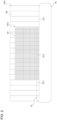
- Fig. 2 is a schematic diagram showing light distribution patterns that the lamps form.
- Fig. 2 shows the maximum range in which the lamps can form light distribution patterns.
- a light distribution pattern is understood as a two-dimensional illuminance distribution of an illumination pattern that a lamp forms on an imaginary vertical screen ahead of the host vehicle. Note that Fig. 2 shows light distribution patterns for left-hand traffic.
- the low beam lamp 2 can form a low beam light distribution pattern PL.
- the low beam light distribution pattern PL has a cutoff line CL at its upper end.
- the cutoff line CL includes a first partial cutoff line CL1, a second partial cutoff line CL2, and a third partial cutoff line CL3.
- the first partial cutoff line CL1 extends in the horizontal direction in the oncoming lane.
- the second partial cutoff line CL2 extends in the horizontal direction in the host vehicle's lane and at a position higher than the position of the first partial cutoff line CL1.
- the third partial cutoff line CL3 extends diagonally between the first partial cutoff line CL1 and the second partial cutoff line CL2 so as to connect the first partial cutoff line CL1 and the second partial cutoff line CL2.
- the first light distribution variable lamp 4 can form a first light distribution pattern PV1 of a variable intensity distribution.
- Fig. 2 shows a first light distribution pattern PV1 formed when the first light distribution variable lamp 4 has turned on all the light sources in its light source array.
- the first light distribution pattern PV1 is a pattern that overlaps a region above the cutoff line CL and is formed, for example, in a region in which any known high beam light distribution patterns are to be formed.
- the first light distribution pattern PV1 has a structure in which a set of a plurality of first partial regions R1 are arrayed in a matrix.
- the light sources of the first light distribution variable lamp 4 are mapped one-to-one to the first partial regions R1.
- the illuminance of the first partial regions R1 can be adjusted independently of each other by adjusting the lighting state of the light sources.
- the second light distribution variable lamp 6 can form a second light distribution pattern PV2 of a variable intensity distribution.
- Fig. 2 shows a second light distribution pattern PV2 formed when the second light distribution variable lamp 6 has turned on all the light sources in its light source unit.
- the second light distribution pattern PV2 is a pattern that overlaps a region above the cutoff line CL and is formed, for example, in a region that encompasses the first light distribution pattern PV1.
- the second light distribution pattern PV2 has a structure in which a set of a plurality of second partial regions R2 are arrayed in the width direction of the vehicle (in the horizontal direction).
- the second partial regions R2 each have, for example, a rectangular shape elongated in the vertical direction and are longer than the first light distribution pattern PV1 in the vertical direction.
- the light sources of the second light distribution variable lamp 6 are mapped one-to-one to the second partial regions R2.
- the illuminance of the second partial regions R2 can be adjusted independently of each other by adjusting the lighting state of the light
- the second light distribution pattern PV2 is projected so as to extend outside the first light distribution pattern PV1 in the width direction of the vehicle. Therefore, some of the second partial regions R2 overlap the first light distribution pattern PV1 in a center portion in the width direction of the vehicle, and the other second partial regions R2 lie outside the first light distribution pattern PV1 at the two ends in the width direction of the vehicle. Note that the shapes and the arrangement of the first partial regions R1 and the second partial regions R2 can be changed as appropriate along with, for example, the arrangement of the light sources in the first light distribution variable lamp 4 and the second light distribution variable lamp 6.
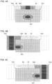
- Figs. 3A to 3C are schematic diagrams showing one example of light distribution control according to Embodiment 1.
- Fig. 3A shows light distribution patterns formed when the steering angle is 0°.
- Fig. 3B shows light distribution patterns formed when the steering is turned to the left.
- Fig. 3C shows light distribution patterns formed when the steering is turned to the right.
- Figs. 3A to 3C omit depicting a low beam light distribution pattern PL.
- the light distribution controlling device 8 controls the first light distribution variable lamp 4 so as to form a first light distribution pattern PV1 having a first hot zone HZ1.
- the first hot zone HZ1 is a region having an illuminance (luminous intensity) higher than that of the remaining region in the first light distribution pattern PV1.
- the first hot zone HZ1 is formed in the part of the region ahead of the host vehicle where particularly high visibility is required.
- the light distribution controlling device 8 controls the first light distribution variable lamp 4 so as to form a first hot zone HZ1 above a cutoff line CL.
- the first hot zone HZ1 is disposed at substantially the center in the width direction of the vehicle.
- the dimension of the first hot zone HZ1 in the vertical direction is, for example, no more than a half the dimension of the first light distribution pattern PV1 in the vertical direction
- the dimension of the first hot zone HZ1 in the horizontal direction is, for example, no more than a half the dimension of the first light distribution pattern PV1 in the horizontal direction.
- Fig. 3A shows a first hot zone HZ1 of an elliptical shape
- the shape of a first hot zone HZ1 is not limited to the one shown.
- Fig. 3A shows a first hot zone HZ1 having such an illuminance gradient where the illuminance decreases gradually from the center toward the outer side, a first hot zone HZ1 does not have to have such an illuminance gradient.
- the light distribution controlling device 8 controls the second light distribution variable lamp 6 so as to form a second light distribution pattern PV2 in which the second partial regions R2 that are located at the outer sides in the width direction of the vehicle and that do not overlap the first light distribution pattern PV1 have an illuminance of zero and in which the second partial regions R2 that overlap the first light distribution pattern PV1 have an illuminance of higher than zero.
- the second light distribution pattern PV2 is constituted only by some of the second partial regions R2 and the second partial regions R2 that do not constitute the second light distribution pattern PV2, that is, the second partial regions R2 that have an illuminance of zero are moved in the width direction of the vehicle as described above, the second light distribution pattern PV2 can be swiveled in the range between the outer left side and the outer right side of the first light distribution pattern PV1.
- the light distribution controlling device 8 controls the second light distribution variable lamp 6 so as to form a second hot zone HZ2 within the second light distribution pattern PV2.
- the light distribution controlling device 8 controls the second light distribution variable lamp 6 so as to form a second hot zone HZ2 above a cutoff line CL.
- the light distribution controlling device 8 controls the second light distribution variable lamp 6 so as to form the second hot zone HZ2 at a position where the second hot zone HZ2 overlaps the first hot zone HZ1 in the width direction of the vehicle.
- the second partial regions R2 are longer than the first light distribution pattern PV1 in the vertical direction. Therefore, the second hot zone HZ2 is longer than the first hot zone HZ1 in the vertical direction.
- the light distribution controlling device 8 controls the first light distribution variable lamp 4 so as to swivel the first hot zone HZ1 within the first light distribution pattern PV1 (i.e., so as to displace the first hot zone HZ1 in the width direction of the vehicle), as shown in Figs. 3B and 3C .
- the light distribution controlling device 8 acquires a signal from a steering angle sensor 20 (steering sensor) provided in the vehicle (see Fig. 1 ).
- the light distribution controlling device 8 then swivels the first hot zone HZ1 in accordance with the output value of the steering angle sensor 20. This swiveling can displace the first hot zone HZ1 in the direction of turn of the vehicle and thus improve the visibility of where the vehicle turns to.
- swiveling the first hot zone HZ1 renders unnecessary a mechanism for swiveling the first light distribution variable lamp 4.
- the light distribution controlling device 8 controls the second light distribution variable lamp 6 so as to swivel the second light distribution pattern PV2 in tandem with the swiveling of the first hot zone HZ1. Then, with the first hot zone HZ1 having reached an end of the first light distribution pattern PV1, the light distribution controlling device 8 controls the second light distribution variable lamp 6 so as to form the second light distribution pattern PV2 outside the first light distribution pattern PV1 where the first hot zone HZ1 has swiveled to.
- This configuration makes it possible to illuminate with light a broader range in the direction of turn of the vehicle and can improve the visibility for the driver.
- the light distribution controlling device 8 controls the second light distribution variable lamp 6 so as to swivel the second hot zone HZ2 with it overlapping the first hot zone HZ1 within the range of the first light distribution pattern PV1.
- the light distribution controlling device 8 further controls the second light distribution variable lamp 6 so as to displace the second hot zone HZ2 further outward after the first hot zone HZ1 has reached an end of the first light distribution pattern PV1.
- the light distribution controlling device 8 displaces the second hot zone HZ2 outside the end of the first light distribution pattern PV1 when a first hot zone HZ1 has reached the end of the first light distribution pattern PV1 and the steering angle has increased further. This configuration can further improve the visibility of where the vehicle turns to.
- the light distribution controlling device 8 controls the first light distribution variable lamp 4 so as to turn off the first hot zone HZ1 that has reached an end of the first light distribution pattern PV1.
- the light distribution controlling device 8 turns off the first hot zone HZ1 that has reached an end of the first light distribution pattern PV1, in accordance with the steering angle.
- the light distribution controlling device 8 gradually turns off the first hot zone HZ1 when the steering angle further increases after the first hot zone HZ1 has reached an end of the first light distribution pattern PV1, that is, when the second hot zone HZ2 moves to the outer side in the width direction of the vehicle from the end of the first light distribution pattern PV1.
- the illuminance of the first hot zone HZ1 decreases from the center side in the width direction of the vehicle, and the first hot zone HZ1 is turned off gradually from the center side in the width direction of the vehicle.
- This configuration can make a hot zone look as if it moves out of the region in which the first light distribution pattern PV1 is formed (into the region in which the second light distribution pattern PV2 is formed) in a combined light distribution pattern of the first light distribution pattern PV1 and the second light distribution pattern PV2 combined.
- This configuration makes it possible to guide the driver's line of sight to where the vehicle turns to.
- a first hot zone HZ1 may be turned off gradually as the illuminance across the entire first hot zone HZ1 is reduced uniformly.
- the light distribution controlling device 8 controls the first light distribution variable lamp 4 and the second light distribution variable lamp 6 so as to swivel the first hot zone HZ1 within the first light distribution pattern PV1 and to form the second light distribution pattern PV2 outside the first light distribution pattern PV1 where the first hot zone HZ1 swivels to.
- one of the light distribution variable lamps swivels a hot zone, and the other light distribution variable lamp illuminates with light the region outside the range in which the hot zone is swiveled.
- a combination of these two light distribution variable lamps in this manner allows for a lamp design of equipping one of the light distribution variable lamp with a high-definition light source array and equipping the other light distribution variable lamp with a low-definition light source unit. This design can improve the visibility for the driver while avoiding an increase in the size of the light source array.
- the light distribution controlling device 8 controls the second light distribution variable lamp 6 so as to swivel the second light distribution pattern PV2 in tandem with the swiveling of the first hot zone HZ1.
- the light distribution controlling device 8 controls the second light distribution variable lamp 6 so as to swivel the second hot zone HZ2 with it overlapping the first hot zone HZ1 within the range of the first light distribution pattern PV1 and to displace the second hot zone HZ2 further outward after the first hot zone HZ1 has reached an end of the first light distribution pattern PV1.
- the light distribution controlling device 8 controls the first light distribution variable lamp 4 so as to turn off the first hot zone HZ1 that has reached the end of the first light distribution pattern PV1.
- the control above can further improve the visibility for the driver. In addition, the control above can guide the driver's line of sight to the region where he or she needs to pay attention to.
- Embodiment 2 has a configuration identical to the configuration of Embodiment 1 except for the content of control by the light distribution control device 8.
- the present embodiment will be described below with the description centered on its configuration that differs from the configuration of Embodiment 1, and description of the configurations that are common to both embodiments will be simplified or omitted.
- Figs. 4A to 4C are schematic diagrams showing one example of light distribution control according to Embodiment 2.
- Fig. 4A shows light distribution patterns formed when the steering angle is 0°.
- Fig. 4B shows light distribution patterns formed when the steering is turned to the left.
- Fig. 4C shows light distribution patterns formed when the steering is turned to the right.
- Figs. 4A to 4C omit depicting a low beam light distribution pattern PL.
- the light distribution controlling device 8 controls the first light distribution variable lamp 4 so as to form a first light distribution pattern PV1 having a first hot zone HZ1.
- the light distribution controlling device 8 controls the second light distribution variable lamp 6 so as to form a second light distribution pattern PV2 with only some of the second partial regions R2. This configuration makes it possible to displace the second light distribution pattern PV2 in the range between the outer left side and the outer right side of the first light distribution pattern PV1.
- the light distribution controlling device 8 controls the second light distribution variable lamp 6 so as to form a second hot zone HZ2 within the second light distribution pattern PV2.
- the second hot zone HZ2 is formed at a position where the second hot zone HZ2 overlaps the first hot zone HZ1 in the width direction of the vehicle.
- the light distribution controlling device 8 then controls the first light distribution variable lamp 4 so as to swivel the first hot zone HZ1 within the first light distribution pattern PV1, as shown in Figs. 4B and 4C .
- the light distribution controlling device 8 controls the second light distribution variable lamp 6 so as to swivel the second light distribution pattern PV2 in tandem with the swiveling of the first hot zone HZ1.
- the light distribution controlling device 8 controls the second light distribution variable lamp 6 so as to form the second light distribution pattern PV2 outside the first light distribution pattern PV1 where the first hot zone HZ1 has swiveled to.
- the light distribution controlling device 8 controls the second light distribution variable lamp 6 so as to swivel the second hot zone HZ2 with it overlapping the first hot zone HZ1 within the range of the first light distribution pattern PV1.
- the light distribution controlling device 8 further controls the second light distribution variable lamp 6 so as to displace the second hot zone HZ2 further outward after the first hot zone HZ1 has reached the end of the first light distribution pattern PV1.
- the light distribution controlling device 8 controls the first light distribution variable lamp 4 so as to maintain the first hot zone HZ1 that has reached the end of the first light distribution pattern PV1.
- a broader region ahead of the host vehicle can be illuminated brightly through a combination of the first hot zone HZ1 and the second hot zone HZ2.
- This configuration can provide the driver with a sense of comfort.
- turning off the first hot zone HZ1 may cause the driver of the host vehicle to feel visually disturbed. Therefore, maintaining the first hot zone HZ1 can keep the driver from feeling visually disturbed.
- Embodiment 3 has a configuration identical to the configuration of Embodiment 1 except for the content of control by the light distribution control device 8.
- the present embodiment will be described below with the description centered on its configuration that differs from the configuration of Embodiment 1, and description of the configurations that are common to both embodiments will be simplified or omitted.
- Figs. 5A to 5C are schematic diagrams showing one example of light distribution control according to Embodiment 3.
- Fig. 5A shows light distribution patterns formed when the steering angle is 0°.
- Fig. 5B shows light distribution patterns formed when the steering is turned to the left.
- Fig. 5C shows light distribution patterns formed when the steering is turned to the right.
- Figs. 5A to 5C omit depicting a low beam light distribution pattern PL.
- the light distribution controlling device 8 controls the first light distribution variable lamp 4 so as to form a first light distribution pattern PV1 having a first hot zone HZ1.
- the light distribution controlling device 8 controls the second light distribution variable lamp 6 so as to form a second light distribution pattern PV2 with only some of the second partial regions R2. This configuration makes it possible to displace the second light distribution pattern PV2 in the range between the outer left side and the outer right side of the first light distribution pattern PV1.
- the second light distribution pattern PV2 according to the present embodiment does not include a second hot zone HZ2 and has an illuminance uniform across the entire second light distribution pattern PV2.
- the light distribution controlling device 8 then controls the first light distribution variable lamp 4 so as to swivel the first hot zone HZ1 within the first light distribution pattern PV1, as shown in Figs. 5B and 5C .
- the light distribution controlling device 8 controls the second light distribution variable lamp 6 so as to swivel the second light distribution pattern PV2 in tandem with the swiveling of the first hot zone HZ1.
- the light distribution controlling device 8 controls the second light distribution variable lamp 6 so as to form the second light distribution pattern PV2 outside the first light distribution pattern PV1 where the first hot zone HZ1 has swiveled to.
- the light distribution controlling device 8 controls the first light distribution variable lamp 4 so as to maintain the first hot zone HZ1 that has reached the end of the first light distribution pattern PV1.
- Embodiment 4 has a configuration identical to the configuration of Embodiment 1 except for the content of control by the light distribution control device 8.
- the present embodiment will be described below with the description centered on its configuration that differs from the configuration of Embodiment 1, and description of the configurations that are common to both embodiments will be simplified or omitted.
- Figs. 6A to 6C are schematic diagrams showing one example of light distribution control according to Embodiment 4.
- Fig. 6A shows light distribution patterns formed when the steering angle is 0°.
- Fig. 6B shows light distribution patterns formed when the steering is turned to the left.
- Fig. 6C shows light distribution patterns formed when the steering is turned to the right.
- Figs. 6A to 6C omit depicting a low beam light distribution pattern PL.
- the light distribution controlling device 8 controls the first light distribution variable lamp 4 so as to form a first light distribution pattern PV1 having a first hot zone HZ1.
- the light distribution controlling device 8 controls the second light distribution variable lamp 6 so as to form a second light distribution pattern PV2 with only some of the second partial regions R2. This configuration makes it possible to displace the second light distribution pattern PV2 in the range between the outer left side and the outer right side of the first light distribution pattern PV1.
- the second light distribution pattern PV2 according to the present embodiment does not include a second hot zone HZ2 and has an illuminance uniform across the entire second light distribution pattern PV2.
- the light distribution controlling device 8 then controls the first light distribution variable lamp 4 so as to swivel the first hot zone HZ1 within the first light distribution pattern PV1, as shown in Figs. 6B and 6C .
- the light distribution controlling device 8 controls the second light distribution variable lamp 6 so as to swivel the second light distribution pattern PV2 in tandem with the swiveling of the first hot zone HZ1.
- the light distribution controlling device 8 controls the second light distribution variable lamp 6 so as to form the second light distribution pattern PV2 outside the first light distribution pattern PV1 where the first hot zone HZ1 has swiveled to.
- the light distribution controlling device 8 controls the first light distribution variable lamp 4 so as to gradually turn off the first hot zone HZ1 when the steering angle further increases after the first hot zone HZ1 has reached the end of the first light distribution pattern PV1.
- the first hot zone HZ1 that has reached the end of the first light distribution pattern PV1 is turned off gradually from the center side in the width direction of the vehicle.
- the first hot zone HZ1 may be turned off gradually as the illuminance across the entire first hot zone HZ1 is reduced uniformly.
- Embodiment 5 has a configuration identical to the configuration of Embodiment 1 except for the content of control by the light distribution control device 8.
- the present embodiment will be described below with the description centered on its configuration that differs from the configuration of Embodiment 1, and description of the configurations that are common to both embodiments will be simplified or omitted.
- Figs. 7A to 7C are schematic diagrams showing one example of light distribution control according to Embodiment 5.
- Fig. 7A shows light distribution patterns formed when the steering angle is 0°.
- Fig. 7B shows light distribution patterns formed when the steering is turned to the left by a first angle.
- Fig. 7C shows light distribution patterns formed when the steering is turned to the left by a second angle greater than the first angle.
- Figs. 7A to 7C omit depicting a low beam light distribution pattern PL.
- the light distribution controlling device 8 controls the first light distribution variable lamp 4 so as to form a first light distribution pattern PV1 having a first hot zone HZ1.
- the light distribution controlling device 8 refrains from forming a second light distribution pattern PV2 until the first hot zone HZ1 reaches an end of the first light distribution pattern PV1.
- the light distribution controlling device 8 controls the first light distribution variable lamp 4 so as to swivel the first hot zone HZ1 within the first light distribution pattern PV1 in accordance with the steering, as shown in Fig. 7B . Then, as shown in Fig. 7C , with the first hot zone HZ1 having reached the end of the first light distribution pattern PV1, the light distribution controlling device 8 controls the second light distribution variable lamp 6 so as to form a second light distribution pattern PV2 outside the first light distribution pattern PV1 where the first hot zone HZ1 has swiveled to. For example, the light distribution controlling device 8 controls the second light distribution variable lamp 6 so as to form the second light distribution pattern PV2 when the steering angle has increased further after the first hot zone HZ1 has reached the end of the first light distribution pattern PV1.
- the second light distribution pattern PV2 formed in this case includes a second partial region R2 adjacent to the first light distribution pattern PV1 in the width direction of the vehicle and having an illuminance comparable to the illuminance of the first hot zone HZ1.
- the illuminance comparable to the illuminance of the first hot zone HZ1 is, for example, the illuminance the same as the illuminance of the first hot zone HZ1.
- this illuminance is an illuminance that, for example, allows a region having this illuminance to function as a hot zone in a combined light distribution pattern of the first light distribution pattern PV1 and the second light distribution pattern PV2 combined.
- the hot zone of the combined light distribution pattern moves from the region of the first light distribution pattern PV1 to the region of the second light distribution pattern PV2 while the steering angle increases.
- the second partial regions R2 are longer than the first light distribution pattern PV1 in the vertical direction. Therefore, when the hot zone of the combined light distribution pattern moves from the region of the first light distribution pattern PV1 to the region of the second light distribution pattern PV2, the size of the hot zone changes suddenly. This sudden change in the size of the hot zone may cause the driver to feel visually disturbed.
- the size of the hot zone also changes suddenly in a similar manner when the hot zone of the combined light distribution pattern moves back from the region of the second light distribution pattern PV2 to the region of the first light distribution pattern PV1 while the steering angle decreases, and this sudden change may cause the driver to feel visually disturbed.
- the light distribution controlling device 8 controls the first light distribution variable lamp 4 so as to expand the first hot zone HZ1 in the vertical direction as the first hot zone HZ1 approaches an end of the first light distribution pattern PV1, as shown in Figs. 7B and 7C .
- This configuration can keep the size of the hot zone from changing suddenly when the hot zone of the combined light distribution pattern moves across the region of the first light distribution pattern PV1 and the region of the second light distribution pattern PV2. Accordingly, the visibility for the driver can be improved.
- the light distribution controlling device 8 may control the second light distribution variable lamp 6 so as to swivel the second light distribution pattern PV2 having an illuminance uniform thereacross, as in Embodiment 3 or 4, until the first hot zone HZ1 reaches an end of the first light distribution pattern PV1. Even this case may cause the driver to feel visually disturbed when the hot zone moves across the region of the first light distribution pattern PV1 and the region of the second light distribution pattern PV2. Therefore, it is effective to expand the first hot zone HZ1 in the vertical direction as the first hot zone HZ1 approaches an end of the first light distribution pattern PV1.
- a vehicle lamp system (1) comprising:
- the vehicle lamp system (1) according to any one of First Item to Third Item, wherein the light distribution controlling device (8) controls the first light distribution variable lamp (4) so as to turn off the first hot zone (HZ1) that has reached an end of the first light distribution pattern (PV1).
- the vehicle lamp system (1) according to any one of First Item to Fifth Item, further comprising:
- a light distribution controlling device (8) that controls formation of light distribution patterns by a first light distribution variable lamp (4) and a second light distribution variable lamp (6), the first light distribution variable lamp (4) forming, in a region ahead of a vehicle, a first light distribution pattern (PV1) having a first hot zone (HZ1), the second light distribution variable lamp (6) forming a second light distribution pattern (PV2) outside the first light distribution pattern (PV1) in a width direction of the vehicle, the light distribution controlling device (8) configured to: control the first light distribution variable lamp (4) and the second light distribution variable lamp (6) so as to swivel the first hot zone (HZ1) within the first light distribution pattern (PV1) and to form the second light distribution pattern (PV2) outside the first light distribution pattern (PV1) where the first hot zone (HZ1) swivels to.
- the present invention can be used in vehicle lamp systems, light distribution controlling devices, and light distribution controlling methods.
- 1 vehicle lamp system 2 low beam lamp, 4 first light distribution variable lamp, 6 second light distribution variable lamp, 8 light distribution controlling device, CL cutoff line, HZ1 first hot zone, HZ2 second hot zone, PL low beam light distribution pattern, PV1 first light distribution pattern, PV2 second light distribution pattern, R1 first partial region, R2 second partial region
Landscapes
- Engineering & Computer Science (AREA)
- General Engineering & Computer Science (AREA)
- Physics & Mathematics (AREA)
- Mechanical Engineering (AREA)
- Microelectronics & Electronic Packaging (AREA)
- Optics & Photonics (AREA)
- Mathematical Physics (AREA)
- Lighting Device Outwards From Vehicle And Optical Signal (AREA)
Abstract
Description
- The present invention relates to vehicle lamp systems, light distribution controlling devices, and light distribution controlling methods.
- Vehicle lamps have been proposed in recent years that use a high-definition light source array in which light sources, such as LEDs, are arrayed in a matrix (see, for example, Patent Literature 1).
- Patent Literature 1:
JP 2008-094127 - Typically, high beam light distribution patterns that vehicle lamps form include a portion called a hot zone that has a high illuminance or luminous intensity. Illuminating with a hot zone the part of the region ahead of the host vehicle where particularly high visibility is required can improve the visibility for the driver. If a vehicle lamp includes a light source array, a hot zone can be formed by creating a luminous intensity gradient among the light sources.
- Meanwhile, in one known technique, when the driver's line of sight shifts from the front of the vehicle to the direction of turn, such as when the vehicle makes a turn, the optical axes of the vehicle lamps are swiveled in the direction of turn to increase the visibility of where the vehicle turns to. If a vehicle lamp includes a light source array, a hot zone in a high beam light distribution pattern can be swiveled in the direction of turn to increase the visibility of where the vehicle turns to, as with the case of swiveling the optical axes.
- There exists a demand for expanding the range in which a hot zone can be swiveled to improve the visibility for drivers. However, high-definition light source arrays are generally expensive. Moreover, light source arrays do not dissipate heat easily as they have a structure in which a large number of light sources are densely arrayed. Due to these factors, it is desirable not to increase the size of a light source array.
- The present invention has been made in view of such circumstances and is directed, in one aspect, to providing a technology for improving the visibility for a driver while avoiding an increase in the size of a light source array.
- One aspect of the present invention provides a vehicle lamp system. This vehicle lamp system includes a first light distribution variable lamp that forms, in a region ahead of a vehicle, a first light distribution pattern having a first hot zone; a second light distribution variable lamp that forms a second light distribution pattern outside the first light distribution pattern in a width direction of the vehicle; and a light distribution controlling device that controls formation of light distribution patterns by the first light distribution variable lamp and the second light distribution variable lamp. The light distribution controlling device controls the first light distribution variable lamp and the second light distribution variable lamp so as to swivel the first hot zone within the first light distribution pattern and to form the second light distribution pattern outside the first light distribution pattern where the first hot zone swivels to.
- Another aspect of the present invention provides a light distribution controlling device that controls formation of light distribution patterns by a first light distribution variable lamp and a second light distribution variable lamp, the first light distribution variable lamp forming, in a region ahead of a vehicle, a first light distribution pattern having a first hot zone, the second light distribution variable lamp forming a second light distribution pattern outside the first light distribution pattern in a width direction of the vehicle. This light distribution controlling device controls the first light distribution variable lamp and the second light distribution variable lamp so as to swivel the first hot zone within the first light distribution pattern and to form the second light distribution pattern outside the first light distribution pattern where the first hot zone swivels to.
- Another aspect of the present invention provides a light distribution controlling method of controlling formation of light distribution patterns by a first light distribution variable lamp and a second light distribution variable lamp, the first light distribution variable lamp forming, in a region ahead of a vehicle, a first light distribution pattern having a first hot zone, the second light distribution variable lamp forming a second light distribution pattern outside the first light distribution pattern in a width direction of the vehicle. This light distribution controlling method includes controlling the first light distribution variable lamp and the second light distribution variable lamp so as to swivel the first hot zone within the first light distribution pattern and to form the second light distribution pattern outside the first light distribution pattern where the first hot zone swivels to.
- It is to be noted that any combinations of the constituent elements above or an embodiment obtained by converting what is expressed by the present invention between a method, an apparatus, a system, and so forth is also valid as an aspect of the present invention.
- The present invention can improve the visibility for a driver while avoiding an increase in the size of a light source array.
-
- [
Fig. 1] Fig. 1 shows a schematic configuration of a vehicle lamp system according toEmbodiment 1. - [
Fig. 2] Fig. 2 is a schematic diagram showing light distribution patterns that the lamps form. - [
Fig. 3] Figs. 3A to 3C are schematic diagrams showing one example of light distribution control according toEmbodiment 1. - [
Fig. 4] Figs. 4A to 4C are schematic diagrams showing one example of light distribution control according toEmbodiment 2. - [
Fig. 5] Figs. 5A to 5C are schematic diagrams showing one example of light distribution control according to Embodiment 3. - [
Fig. 6] Figs. 6A to 6C are schematic diagrams showing one example of light distribution control according toEmbodiment 4. - [
Fig. 7] Figs. 7A to 7C are schematic diagrams showing one example of light distribution control according to Embodiment 5. - Hereinafter, the present invention will be described based on exemplary embodiments and with reference to the drawings. The embodiments are illustrative in nature and are not intended to limit the invention. Not all the features and combinations thereof described in the embodiments are necessarily essential to the invention. Identical or equivalent constituent elements, members, and processes shown in the drawings are given identical reference characters, and their duplicate description will be omitted, as appropriate. The scales and shapes of the components shown in the drawings are set merely for convenience in order to facilitate the description and are not to be interpreted as limiting, unless specifically indicated otherwise. When terms such as "first" and "second" are used in the present specification or in the claims, these terms do not indicate the order or the level of importance in any way and are merely used to distinguish a given component from another component, unless specifically indicated otherwise. Part of members that is not important in describing the embodiments is omitted from the drawings.
-
Fig. 1 shows a schematic configuration of avehicle lamp system 1 according toEmbodiment 1.Fig. 1 depicts some of the constituent elements of thevehicle lamp system 1 in the form of functional blocks. These functional blocks are implemented, in terms of their hardware configuration, by an element and/or circuit, including a CPU and a memory of a computer, or implemented, in terms of their software configuration, by a computer program or the like. It is to be appreciated by a person skilled in the art that these functional blocks can be implemented in a variety of forms through combinations of hardware and software. - The
vehicle lamp system 1 includes alow beam lamp 2, a first lightdistribution variable lamp 4, a second lightdistribution variable lamp 6, and a light distribution controllingdevice 8. These members may be contained within a single housing, or one or more of these members may be provided outside such a housing. For example, thelow beam lamp 2, the first lightdistribution variable lamp 4, the second lightdistribution variable lamp 6, and the light distribution controllingdevice 8 are housed in a lamp room. The lamp room is defined by a lamp body having an opening that opens to the front of the vehicle and a light-transmissive cover attached so as to cover the opening of the lamp body. The light distribution controllingdevice 8 may be provided outside the lamp room, such as in the vehicle. In this case, the light distribution controllingdevice 8 may be entirely or partly constituted by a vehicle ECU. Meanwhile, thelow beam lamp 2, the first lightdistribution variable lamp 4, and the second lightdistribution variable lamp 6 may be entirely or partly housed in separate housings. - The
low beam lamp 2 in one example includes a lightsource mounting portion 10, alight source 12, areflector 14, ashade member 16, and aprojection lens 18. The lightsource mounting portion 10 is formed, for example, of a metal material, such as aluminum, and is supported on the lamp body via a bracket (not shown). The lightsource mounting portion 10 has a lightsource mounting surface 10a. The lightsource mounting surface 10a according to the present embodiment extends in a substantially horizontal direction. Thelight source 12 is mounted on the lightsource mounting surface 10a. - The
light source 12 is, for example, a light-emitting diode (LED). Herein, thelight source 12 may instead, for example, be a semiconductor light source other than an LED, such as a laser diode (LD) or an organic or inorganic electroluminescence (EL) light source, an incandescent lamp, a halogen lamp, or a discharge lamp. Thelight source 12 emits light toward thereflector 14. Thereflector 14 has a substantially dome-like shape. Thereflector 14 is disposed so as to cover thelight source 12 from directly above in the vertical direction and is fixed to the lightsource mounting portion 10. Thereflector 14 has areflective surface 14a formed by a part of a spheroidal surface. Thereflective surface 14a has a first focal point and a second focal point that is located further to the front of the lamp than the first focal point. The positional relationship of thereflector 14 and thelight source 12 is set such that thelight source 12 substantially coincides with the first focal point of thereflective surface 14a. - The
shade member 16 is fixed to the side of the lightsource mounting portion 10 that faces the front of the lamp. Theshade member 16 includes aflat portion 16a extending substantially horizontally and acurved portion 16b located further to the front of the lamp than theflat portion 16a. Thecurved portion 16b is curved downward so as not to block the light source light from entering theprojection lens 18. The positional relationship of thereflector 14 and theshade member 16 is set such that aridge 16c formed by theflat portion 16a and thecurved portion 16b is located near the second focal point of thereflective surface 14a. Theprojection lens 18 is fixed to the leading end of thecurved portion 16b. Theprojection lens 18 is formed, for example, by a plano-convex aspherical lens and projects an inverted image of a light source image formed in its posterior focal plane onto an imaginary vertical screen ahead of the lamp. Theprojection lens 18 is disposed in the optical axis of thelow beam lamp 2 such that the posterior focal point of theprojection lens 18 substantially coincides with the second focal point of thereflective surface 14a. - Light emitted from the
light source 12 is reflected by thereflective surface 14a, travels through the vicinity of theridge 16c, and enters theprojection lens 18. The light that has entered theprojection lens 18 is projected into the region ahead of the lamp as substantially parallel light. At this point, theshade member 16 blocks part of the light source light from traveling ahead of the lamp. Specifically, part of the light emitted from thelight source 12 is reflected by theflat portion 16a. In other words, the light from thelight source 12 is selectively cut off at theridge 16c serving as a boundary. Thus, a low beam light distribution pattern including a cutoff line corresponding to the shape of theridge 16c (seeFig. 2 ) is formed in the region ahead of the vehicle. Thelow beam lamp 2 receives a signal instructing it to form a low beam light distribution pattern from the lightdistribution controlling device 8 and forms a low beam light distribution pattern in the region ahead of the host vehicle. - It is to be noted that the structure of the
low beam lamp 2 is not limited to the one described above, and any known structures can be adopted. For example, theshade member 16 that forms a cutoff line may be of a shutter type in which a shade plate moves back and forth with respect to the optical axis. Thelow beam lamp 2 does not have to include thereflector 14 or theprojection lens 18. - The first light
distribution variable lamp 4 is capable of illuminating the region ahead of the vehicle with a visible light beam L1 of a variable intensity distribution. The first lightdistribution variable lamp 4 is supported on the lamp body by a known coupling mechanism (not shown). The first lightdistribution variable lamp 4 is capable of varying, independently of each other, the illuminance of light illuminating a plurality of individual regions arrayed in the region ahead. The first lightdistribution variable lamp 4 receives information instructing on a first light distribution pattern from the lightdistribution controlling device 8 and emits a visible light beam L1 having an intensity distribution corresponding to the first light distribution pattern. Thus, the first light distribution pattern is formed ahead of the host vehicle. - The first light
distribution variable lamp 4 according to the present embodiment includes a light source array. The light source array includes a plurality of light sources arrayed in a matrix and a circuit board capable of adjusting the light of the light sources independently of each other. Preferred examples of such a light source include a semiconductor light-emitting element, such as an LED, an LD, or an organic or inorganic EL light source. The number of the light sources, that is, the resolving power (resolution) of the first lightdistribution variable lamp 4 is higher than the number of the light sources of the second lightdistribution variable lamp 6, that is, higher than the resolving power of the second lightdistribution variable lamp 6 and is, for example, from 1,000 pixels to 1,300,000 pixels. The resolution of a light distribution variable lamp means the number of the unit regions, of a light distribution pattern, whose illuminance can be varied independently of each other. - The second light
distribution variable lamp 6 is capable of illuminating the region ahead of the vehicle with a visible light beam L2 of a variable intensity distribution. The second lightdistribution variable lamp 6 is supported on the lamp body by a known coupling mechanism (not shown). The second lightdistribution variable lamp 6 is capable of varying, independently of each other, the illuminance of light illuminating a plurality of individual regions arrayed in the region ahead. The second lightdistribution variable lamp 6 receives information instructing on a second light distribution pattern from the lightdistribution controlling device 8 and emits a visible light beam L2 having an intensity distribution corresponding to the second light distribution pattern. Thus, the second light distribution pattern is formed ahead of the host vehicle. - The second light
distribution variable lamp 6 according to the present embodiment includes a light source unit constituted by a plurality of light sources arrayed in the horizontal direction and a circuit board capable of adjusting the light of the light sources independently of each other. Preferred examples of such a light source include a semiconductor light-emitting element, such as an LED, an LD, or an organic or inorganic EL light source. The resolving power (resolution) of the second lightdistribution variable lamp 6 is lower than the resolving power of the first lightdistribution variable lamp 4 and is, for example, from 10 pixels to 50 pixels. - It is to be noted that the structures of the first light
distribution variable lamp 4 and the second lightdistribution variable lamp 6 are not limited to those described above, and any known structures can be adopted. For example, in order to form an illuminance distribution corresponding to a light distribution pattern, each light distribution variable lamp may include a pattern forming device of a matrix type, such as a digital mirror device (DMD) or a liquid-crystal device. - The light
distribution controlling device 8 controls formation of light distribution patterns by thelow beam lamp 2, the first lightdistribution variable lamp 4, and the second lightdistribution variable lamp 6. The lightdistribution controlling device 8 can be constituted by a digital processor and may, for example, be constituted by a combination of a microcomputer including a CPU and a software program or by a field-programmable gate array (FPGA), an application specific IC (ASIC), or the like. The lightdistribution control device 8 operates as the integrated circuit constituting itself executes a program stored in a memory. - Now, shapes of light distribution patterns that the lamps form and control of forming the light distribution patterns performed by the light
distribution controlling device 8 will be described.Fig. 2 is a schematic diagram showing light distribution patterns that the lamps form.Fig. 2 shows the maximum range in which the lamps can form light distribution patterns. A light distribution pattern is understood as a two-dimensional illuminance distribution of an illumination pattern that a lamp forms on an imaginary vertical screen ahead of the host vehicle. Note thatFig. 2 shows light distribution patterns for left-hand traffic. - The
low beam lamp 2 can form a low beam light distribution pattern PL. The low beam light distribution pattern PL has a cutoff line CL at its upper end. The cutoff line CL includes a first partial cutoff line CL1, a second partial cutoff line CL2, and a third partial cutoff line CL3. The first partial cutoff line CL1 extends in the horizontal direction in the oncoming lane. The second partial cutoff line CL2 extends in the horizontal direction in the host vehicle's lane and at a position higher than the position of the first partial cutoff line CL1. The third partial cutoff line CL3 extends diagonally between the first partial cutoff line CL1 and the second partial cutoff line CL2 so as to connect the first partial cutoff line CL1 and the second partial cutoff line CL2. - The first light
distribution variable lamp 4 can form a first light distribution pattern PV1 of a variable intensity distribution.Fig. 2 shows a first light distribution pattern PV1 formed when the first lightdistribution variable lamp 4 has turned on all the light sources in its light source array. The first light distribution pattern PV1 is a pattern that overlaps a region above the cutoff line CL and is formed, for example, in a region in which any known high beam light distribution patterns are to be formed. The first light distribution pattern PV1 has a structure in which a set of a plurality of first partial regions R1 are arrayed in a matrix. In one example, the light sources of the first lightdistribution variable lamp 4 are mapped one-to-one to the first partial regions R1. The illuminance of the first partial regions R1 can be adjusted independently of each other by adjusting the lighting state of the light sources. - The second light
distribution variable lamp 6 can form a second light distribution pattern PV2 of a variable intensity distribution.Fig. 2 shows a second light distribution pattern PV2 formed when the second lightdistribution variable lamp 6 has turned on all the light sources in its light source unit. The second light distribution pattern PV2 is a pattern that overlaps a region above the cutoff line CL and is formed, for example, in a region that encompasses the first light distribution pattern PV1. The second light distribution pattern PV2 has a structure in which a set of a plurality of second partial regions R2 are arrayed in the width direction of the vehicle (in the horizontal direction). The second partial regions R2 each have, for example, a rectangular shape elongated in the vertical direction and are longer than the first light distribution pattern PV1 in the vertical direction. In one example, the light sources of the second lightdistribution variable lamp 6 are mapped one-to-one to the second partial regions R2. The illuminance of the second partial regions R2 can be adjusted independently of each other by adjusting the lighting state of the light sources. - The second light distribution pattern PV2 is projected so as to extend outside the first light distribution pattern PV1 in the width direction of the vehicle. Therefore, some of the second partial regions R2 overlap the first light distribution pattern PV1 in a center portion in the width direction of the vehicle, and the other second partial regions R2 lie outside the first light distribution pattern PV1 at the two ends in the width direction of the vehicle. Note that the shapes and the arrangement of the first partial regions R1 and the second partial regions R2 can be changed as appropriate along with, for example, the arrangement of the light sources in the first light
distribution variable lamp 4 and the second lightdistribution variable lamp 6. - The light
distribution controlling device 8 executes light distribution control as described below.Figs. 3A to 3C are schematic diagrams showing one example of light distribution control according toEmbodiment 1.Fig. 3A shows light distribution patterns formed when the steering angle is 0°.Fig. 3B shows light distribution patterns formed when the steering is turned to the left.Fig. 3C shows light distribution patterns formed when the steering is turned to the right.Figs. 3A to 3C omit depicting a low beam light distribution pattern PL. - As shown in
Fig. 3A , the lightdistribution controlling device 8 controls the first lightdistribution variable lamp 4 so as to form a first light distribution pattern PV1 having a first hot zone HZ1. The first hot zone HZ1 is a region having an illuminance (luminous intensity) higher than that of the remaining region in the first light distribution pattern PV1. The first hot zone HZ1 is formed in the part of the region ahead of the host vehicle where particularly high visibility is required. In one example, the lightdistribution controlling device 8 controls the first lightdistribution variable lamp 4 so as to form a first hot zone HZ1 above a cutoff line CL. When the steering angle is 0°, the first hot zone HZ1 is disposed at substantially the center in the width direction of the vehicle. The dimension of the first hot zone HZ1 in the vertical direction is, for example, no more than a half the dimension of the first light distribution pattern PV1 in the vertical direction, and the dimension of the first hot zone HZ1 in the horizontal direction is, for example, no more than a half the dimension of the first light distribution pattern PV1 in the horizontal direction. - Although
Fig. 3A shows a first hot zone HZ1 of an elliptical shape, the shape of a first hot zone HZ1 is not limited to the one shown. Furthermore, althoughFig. 3A shows a first hot zone HZ1 having such an illuminance gradient where the illuminance decreases gradually from the center toward the outer side, a first hot zone HZ1 does not have to have such an illuminance gradient. - The light
distribution controlling device 8 controls the second lightdistribution variable lamp 6 so as to form a second light distribution pattern PV2 in which the second partial regions R2 that are located at the outer sides in the width direction of the vehicle and that do not overlap the first light distribution pattern PV1 have an illuminance of zero and in which the second partial regions R2 that overlap the first light distribution pattern PV1 have an illuminance of higher than zero. When the second light distribution pattern PV2 is constituted only by some of the second partial regions R2 and the second partial regions R2 that do not constitute the second light distribution pattern PV2, that is, the second partial regions R2 that have an illuminance of zero are moved in the width direction of the vehicle as described above, the second light distribution pattern PV2 can be swiveled in the range between the outer left side and the outer right side of the first light distribution pattern PV1. - The light
distribution controlling device 8 controls the second lightdistribution variable lamp 6 so as to form a second hot zone HZ2 within the second light distribution pattern PV2. In one example, the lightdistribution controlling device 8 controls the second lightdistribution variable lamp 6 so as to form a second hot zone HZ2 above a cutoff line CL. The lightdistribution controlling device 8 controls the second lightdistribution variable lamp 6 so as to form the second hot zone HZ2 at a position where the second hot zone HZ2 overlaps the first hot zone HZ1 in the width direction of the vehicle. As mentioned above, the second partial regions R2 are longer than the first light distribution pattern PV1 in the vertical direction. Therefore, the second hot zone HZ2 is longer than the first hot zone HZ1 in the vertical direction. - The light
distribution controlling device 8 then controls the first lightdistribution variable lamp 4 so as to swivel the first hot zone HZ1 within the first light distribution pattern PV1 (i.e., so as to displace the first hot zone HZ1 in the width direction of the vehicle), as shown inFigs. 3B and 3C . For example, the lightdistribution controlling device 8 acquires a signal from a steering angle sensor 20 (steering sensor) provided in the vehicle (seeFig. 1 ). The lightdistribution controlling device 8 then swivels the first hot zone HZ1 in accordance with the output value of thesteering angle sensor 20. This swiveling can displace the first hot zone HZ1 in the direction of turn of the vehicle and thus improve the visibility of where the vehicle turns to. Furthermore, swiveling the first hot zone HZ1 renders unnecessary a mechanism for swiveling the first lightdistribution variable lamp 4. - The light
distribution controlling device 8 controls the second lightdistribution variable lamp 6 so as to swivel the second light distribution pattern PV2 in tandem with the swiveling of the first hot zone HZ1. Then, with the first hot zone HZ1 having reached an end of the first light distribution pattern PV1, the lightdistribution controlling device 8 controls the second lightdistribution variable lamp 6 so as to form the second light distribution pattern PV2 outside the first light distribution pattern PV1 where the first hot zone HZ1 has swiveled to. This configuration makes it possible to illuminate with light a broader range in the direction of turn of the vehicle and can improve the visibility for the driver. To "form a second light distribution pattern PV2 outside a first light distribution pattern PV1" means that at least a part of the second light distribution pattern PV2 is located outside the first light distribution pattern PV1. Therefore, the above expression encompasses a state in which a part of the second light distribution pattern PV2 overlaps the first light distribution pattern PV1 as shown inFig. 3B or 3C . - The light
distribution controlling device 8 controls the second lightdistribution variable lamp 6 so as to swivel the second hot zone HZ2 with it overlapping the first hot zone HZ1 within the range of the first light distribution pattern PV1. The lightdistribution controlling device 8 further controls the second lightdistribution variable lamp 6 so as to displace the second hot zone HZ2 further outward after the first hot zone HZ1 has reached an end of the first light distribution pattern PV1. For example, the lightdistribution controlling device 8 displaces the second hot zone HZ2 outside the end of the first light distribution pattern PV1 when a first hot zone HZ1 has reached the end of the first light distribution pattern PV1 and the steering angle has increased further. This configuration can further improve the visibility of where the vehicle turns to. - The light
distribution controlling device 8 controls the first lightdistribution variable lamp 4 so as to turn off the first hot zone HZ1 that has reached an end of the first light distribution pattern PV1. In one example, the lightdistribution controlling device 8 turns off the first hot zone HZ1 that has reached an end of the first light distribution pattern PV1, in accordance with the steering angle. For example, the lightdistribution controlling device 8 gradually turns off the first hot zone HZ1 when the steering angle further increases after the first hot zone HZ1 has reached an end of the first light distribution pattern PV1, that is, when the second hot zone HZ2 moves to the outer side in the width direction of the vehicle from the end of the first light distribution pattern PV1. In the example shown inFigs. 3B and 3C , the illuminance of the first hot zone HZ1 decreases from the center side in the width direction of the vehicle, and the first hot zone HZ1 is turned off gradually from the center side in the width direction of the vehicle. - This configuration can make a hot zone look as if it moves out of the region in which the first light distribution pattern PV1 is formed (into the region in which the second light distribution pattern PV2 is formed) in a combined light distribution pattern of the first light distribution pattern PV1 and the second light distribution pattern PV2 combined. This configuration makes it possible to guide the driver's line of sight to where the vehicle turns to. Herein, a first hot zone HZ1 may be turned off gradually as the illuminance across the entire first hot zone HZ1 is reduced uniformly.
- As described above, the light
distribution controlling device 8 according to the present embodiment controls the first lightdistribution variable lamp 4 and the second lightdistribution variable lamp 6 so as to swivel the first hot zone HZ1 within the first light distribution pattern PV1 and to form the second light distribution pattern PV2 outside the first light distribution pattern PV1 where the first hot zone HZ1 swivels to. In other words, one of the light distribution variable lamps swivels a hot zone, and the other light distribution variable lamp illuminates with light the region outside the range in which the hot zone is swiveled. - A combination of these two light distribution variable lamps in this manner allows for a lamp design of equipping one of the light distribution variable lamp with a high-definition light source array and equipping the other light distribution variable lamp with a low-definition light source unit. This design can improve the visibility for the driver while avoiding an increase in the size of the light source array.
- The light
distribution controlling device 8 controls the second lightdistribution variable lamp 6 so as to swivel the second light distribution pattern PV2 in tandem with the swiveling of the first hot zone HZ1. The lightdistribution controlling device 8 controls the second lightdistribution variable lamp 6 so as to swivel the second hot zone HZ2 with it overlapping the first hot zone HZ1 within the range of the first light distribution pattern PV1 and to displace the second hot zone HZ2 further outward after the first hot zone HZ1 has reached an end of the first light distribution pattern PV1. The lightdistribution controlling device 8 controls the first lightdistribution variable lamp 4 so as to turn off the first hot zone HZ1 that has reached the end of the first light distribution pattern PV1. The control above can further improve the visibility for the driver. In addition, the control above can guide the driver's line of sight to the region where he or she needs to pay attention to. -
Embodiment 2 has a configuration identical to the configuration ofEmbodiment 1 except for the content of control by the lightdistribution control device 8. The present embodiment will be described below with the description centered on its configuration that differs from the configuration ofEmbodiment 1, and description of the configurations that are common to both embodiments will be simplified or omitted.Figs. 4A to 4C are schematic diagrams showing one example of light distribution control according toEmbodiment 2.Fig. 4A shows light distribution patterns formed when the steering angle is 0°.Fig. 4B shows light distribution patterns formed when the steering is turned to the left.Fig. 4C shows light distribution patterns formed when the steering is turned to the right.Figs. 4A to 4C omit depicting a low beam light distribution pattern PL. - As shown in
Fig. 4A , the lightdistribution controlling device 8 controls the first lightdistribution variable lamp 4 so as to form a first light distribution pattern PV1 having a first hot zone HZ1. The lightdistribution controlling device 8 controls the second lightdistribution variable lamp 6 so as to form a second light distribution pattern PV2 with only some of the second partial regions R2. This configuration makes it possible to displace the second light distribution pattern PV2 in the range between the outer left side and the outer right side of the first light distribution pattern PV1. The lightdistribution controlling device 8 controls the second lightdistribution variable lamp 6 so as to form a second hot zone HZ2 within the second light distribution pattern PV2. The second hot zone HZ2 is formed at a position where the second hot zone HZ2 overlaps the first hot zone HZ1 in the width direction of the vehicle. - The light
distribution controlling device 8 then controls the first lightdistribution variable lamp 4 so as to swivel the first hot zone HZ1 within the first light distribution pattern PV1, as shown inFigs. 4B and 4C . The lightdistribution controlling device 8 controls the second lightdistribution variable lamp 6 so as to swivel the second light distribution pattern PV2 in tandem with the swiveling of the first hot zone HZ1. Then, with the first hot zone HZ1 having reached an end of the first light distribution pattern PV1, the lightdistribution controlling device 8 controls the second lightdistribution variable lamp 6 so as to form the second light distribution pattern PV2 outside the first light distribution pattern PV1 where the first hot zone HZ1 has swiveled to. - The light
distribution controlling device 8 controls the second lightdistribution variable lamp 6 so as to swivel the second hot zone HZ2 with it overlapping the first hot zone HZ1 within the range of the first light distribution pattern PV1. The lightdistribution controlling device 8 further controls the second lightdistribution variable lamp 6 so as to displace the second hot zone HZ2 further outward after the first hot zone HZ1 has reached the end of the first light distribution pattern PV1. - The light
distribution controlling device 8 according to the present embodiment controls the first lightdistribution variable lamp 4 so as to maintain the first hot zone HZ1 that has reached the end of the first light distribution pattern PV1. As the first hot zone HZ1 remains being formed even after the second hot zone HZ2 has moved outside the first light distribution pattern PV1, a broader region ahead of the host vehicle can be illuminated brightly through a combination of the first hot zone HZ1 and the second hot zone HZ2. This configuration can provide the driver with a sense of comfort. When there is a large difference between the maximum illuminance of the first lightdistribution variable lamp 4 and the maximum illuminance of the second lightdistribution variable lamp 6, turning off the first hot zone HZ1 may cause the driver of the host vehicle to feel visually disturbed. Therefore, maintaining the first hot zone HZ1 can keep the driver from feeling visually disturbed. - Embodiment 3 has a configuration identical to the configuration of
Embodiment 1 except for the content of control by the lightdistribution control device 8. The present embodiment will be described below with the description centered on its configuration that differs from the configuration ofEmbodiment 1, and description of the configurations that are common to both embodiments will be simplified or omitted.Figs. 5A to 5C are schematic diagrams showing one example of light distribution control according to Embodiment 3.Fig. 5A shows light distribution patterns formed when the steering angle is 0°.Fig. 5B shows light distribution patterns formed when the steering is turned to the left.Fig. 5C shows light distribution patterns formed when the steering is turned to the right.Figs. 5A to 5C omit depicting a low beam light distribution pattern PL. - As shown in
Fig. 5A , the lightdistribution controlling device 8 controls the first lightdistribution variable lamp 4 so as to form a first light distribution pattern PV1 having a first hot zone HZ1. The lightdistribution controlling device 8 controls the second lightdistribution variable lamp 6 so as to form a second light distribution pattern PV2 with only some of the second partial regions R2. This configuration makes it possible to displace the second light distribution pattern PV2 in the range between the outer left side and the outer right side of the first light distribution pattern PV1. The second light distribution pattern PV2 according to the present embodiment does not include a second hot zone HZ2 and has an illuminance uniform across the entire second light distribution pattern PV2. - The light
distribution controlling device 8 then controls the first lightdistribution variable lamp 4 so as to swivel the first hot zone HZ1 within the first light distribution pattern PV1, as shown inFigs. 5B and 5C . The lightdistribution controlling device 8 controls the second lightdistribution variable lamp 6 so as to swivel the second light distribution pattern PV2 in tandem with the swiveling of the first hot zone HZ1. Then, with the first hot zone HZ1 having reached an end of the first light distribution pattern PV1, the lightdistribution controlling device 8 controls the second lightdistribution variable lamp 6 so as to form the second light distribution pattern PV2 outside the first light distribution pattern PV1 where the first hot zone HZ1 has swiveled to. The lightdistribution controlling device 8 according to the present embodiment controls the first lightdistribution variable lamp 4 so as to maintain the first hot zone HZ1 that has reached the end of the first light distribution pattern PV1. -
Embodiment 4 has a configuration identical to the configuration ofEmbodiment 1 except for the content of control by the lightdistribution control device 8. The present embodiment will be described below with the description centered on its configuration that differs from the configuration ofEmbodiment 1, and description of the configurations that are common to both embodiments will be simplified or omitted.Figs. 6A to 6C are schematic diagrams showing one example of light distribution control according toEmbodiment 4.Fig. 6A shows light distribution patterns formed when the steering angle is 0°.Fig. 6B shows light distribution patterns formed when the steering is turned to the left.Fig. 6C shows light distribution patterns formed when the steering is turned to the right.Figs. 6A to 6C omit depicting a low beam light distribution pattern PL. - As shown in
Fig. 6A , the lightdistribution controlling device 8 controls the first lightdistribution variable lamp 4 so as to form a first light distribution pattern PV1 having a first hot zone HZ1. The lightdistribution controlling device 8 controls the second lightdistribution variable lamp 6 so as to form a second light distribution pattern PV2 with only some of the second partial regions R2. This configuration makes it possible to displace the second light distribution pattern PV2 in the range between the outer left side and the outer right side of the first light distribution pattern PV1. The second light distribution pattern PV2 according to the present embodiment does not include a second hot zone HZ2 and has an illuminance uniform across the entire second light distribution pattern PV2. - The light
distribution controlling device 8 then controls the first lightdistribution variable lamp 4 so as to swivel the first hot zone HZ1 within the first light distribution pattern PV1, as shown inFigs. 6B and 6C . The lightdistribution controlling device 8 controls the second lightdistribution variable lamp 6 so as to swivel the second light distribution pattern PV2 in tandem with the swiveling of the first hot zone HZ1. Then, with the first hot zone HZ1 having reached an end of the first light distribution pattern PV1, the lightdistribution controlling device 8 controls the second lightdistribution variable lamp 6 so as to form the second light distribution pattern PV2 outside the first light distribution pattern PV1 where the first hot zone HZ1 has swiveled to. - The light
distribution controlling device 8 according to the present embodiment controls the first lightdistribution variable lamp 4 so as to gradually turn off the first hot zone HZ1 when the steering angle further increases after the first hot zone HZ1 has reached the end of the first light distribution pattern PV1. In the example shown inFigs. 6B and 6C , the first hot zone HZ1 that has reached the end of the first light distribution pattern PV1 is turned off gradually from the center side in the width direction of the vehicle. Herein, the first hot zone HZ1 may be turned off gradually as the illuminance across the entire first hot zone HZ1 is reduced uniformly. - Embodiment 5 has a configuration identical to the configuration of
Embodiment 1 except for the content of control by the lightdistribution control device 8. The present embodiment will be described below with the description centered on its configuration that differs from the configuration ofEmbodiment 1, and description of the configurations that are common to both embodiments will be simplified or omitted.Figs. 7A to 7C are schematic diagrams showing one example of light distribution control according to Embodiment 5.Fig. 7A shows light distribution patterns formed when the steering angle is 0°.Fig. 7B shows light distribution patterns formed when the steering is turned to the left by a first angle.Fig. 7C shows light distribution patterns formed when the steering is turned to the left by a second angle greater than the first angle.Figs. 7A to 7C omit depicting a low beam light distribution pattern PL. - As shown in
Fig. 7A , the lightdistribution controlling device 8 controls the first lightdistribution variable lamp 4 so as to form a first light distribution pattern PV1 having a first hot zone HZ1. The lightdistribution controlling device 8 according to the present embodiment refrains from forming a second light distribution pattern PV2 until the first hot zone HZ1 reaches an end of the first light distribution pattern PV1. - The light
distribution controlling device 8 controls the first lightdistribution variable lamp 4 so as to swivel the first hot zone HZ1 within the first light distribution pattern PV1 in accordance with the steering, as shown inFig. 7B . Then, as shown inFig. 7C , with the first hot zone HZ1 having reached the end of the first light distribution pattern PV1, the lightdistribution controlling device 8 controls the second lightdistribution variable lamp 6 so as to form a second light distribution pattern PV2 outside the first light distribution pattern PV1 where the first hot zone HZ1 has swiveled to. For example, the lightdistribution controlling device 8 controls the second lightdistribution variable lamp 6 so as to form the second light distribution pattern PV2 when the steering angle has increased further after the first hot zone HZ1 has reached the end of the first light distribution pattern PV1. - The second light distribution pattern PV2 formed in this case includes a second partial region R2 adjacent to the first light distribution pattern PV1 in the width direction of the vehicle and having an illuminance comparable to the illuminance of the first hot zone HZ1. The illuminance comparable to the illuminance of the first hot zone HZ1 is, for example, the illuminance the same as the illuminance of the first hot zone HZ1. Alternatively, this illuminance is an illuminance that, for example, allows a region having this illuminance to function as a hot zone in a combined light distribution pattern of the first light distribution pattern PV1 and the second light distribution pattern PV2 combined. Thus, the hot zone of the combined light distribution pattern moves from the region of the first light distribution pattern PV1 to the region of the second light distribution pattern PV2 while the steering angle increases.
- As mentioned above, the second partial regions R2 are longer than the first light distribution pattern PV1 in the vertical direction. Therefore, when the hot zone of the combined light distribution pattern moves from the region of the first light distribution pattern PV1 to the region of the second light distribution pattern PV2, the size of the hot zone changes suddenly. This sudden change in the size of the hot zone may cause the driver to feel visually disturbed. The size of the hot zone also changes suddenly in a similar manner when the hot zone of the combined light distribution pattern moves back from the region of the second light distribution pattern PV2 to the region of the first light distribution pattern PV1 while the steering angle decreases, and this sudden change may cause the driver to feel visually disturbed.
- In this respect, the light
distribution controlling device 8 according to the present embodiment controls the first lightdistribution variable lamp 4 so as to expand the first hot zone HZ1 in the vertical direction as the first hot zone HZ1 approaches an end of the first light distribution pattern PV1, as shown inFigs. 7B and 7C . This configuration can keep the size of the hot zone from changing suddenly when the hot zone of the combined light distribution pattern moves across the region of the first light distribution pattern PV1 and the region of the second light distribution pattern PV2. Accordingly, the visibility for the driver can be improved. - Herein, the light
distribution controlling device 8 may control the second lightdistribution variable lamp 6 so as to swivel the second light distribution pattern PV2 having an illuminance uniform thereacross, as inEmbodiment 3 or 4, until the first hot zone HZ1 reaches an end of the first light distribution pattern PV1. Even this case may cause the driver to feel visually disturbed when the hot zone moves across the region of the first light distribution pattern PV1 and the region of the second light distribution pattern PV2. Therefore, it is effective to expand the first hot zone HZ1 in the vertical direction as the first hot zone HZ1 approaches an end of the first light distribution pattern PV1. - Thus far, some embodiments according to the present invention have been described in detail. The embodiments described above merely illustrate some specific examples for implementing the present invention. The content of the embodiments does not limit the technical scope of the present invention, and a number of design changes, including modifications, additions, and deletions of constituent elements, can be made within the scope that does not depart from the sprit of the invention set forth in the claims. A new embodiment resulting from adding a design change has advantageous effects of the embodiments combined as well as the advantageous effects of the modification. With regard to the embodiments described above, expressions "according to the present embodiment," "in the present embodiment," and so on are added for emphasis to the content that can be subjected to such a design change, but a design change is also permitted on the content without these expressions. A desired combination of the constituent elements described above is also valid as an aspect of the present invention. Hatching added along a section in the drawings does not limit the material of such with hatching.
- The invention according to the embodiments described above may be identified by the items indicated below.
- A vehicle lamp system (1), comprising:
- a first light distribution variable lamp (4) that forms, in a region ahead of a vehicle, a first light distribution pattern (PV1) having a first hot zone (HZ1);
- a second light distribution variable lamp (6) that forms a second light distribution pattern (PV2) outside the first light distribution pattern (PV1) in a width direction of the vehicle; and
- a light distribution controlling device (8) that controls formation of light distribution patterns by the first light distribution variable lamp (4) and the second light distribution variable lamp (6), wherein
- the light distribution controlling device (8) controls the first light distribution variable lamp (4) and the second light distribution variable lamp (6) so as to swivel the first hot zone (HZ1) within the first light distribution pattern (PV1) and to form the second light distribution pattern (PV2) outside the first light distribution pattern (PV1) where the first hot zone (HZ1) swivels to.
- The vehicle lamp system (1) according to First Item, wherein
- the second light distribution pattern (PV2) can be swiveled in a range between an outer left side and an outer right side of the first light distribution pattern (PV1), and
- the light distribution controlling device (8) controls the second light distribution variable lamp (6) so as to swivel the second light distribution pattern (PV2) in tandem with the swiveling of the first hot zone (HZ1).
- The vehicle lamp system (1) according to Second Item, wherein
- the second light distribution pattern (PV2) includes a second hot zone (HZ2), and
- the light distribution controlling device (8) controls the second light distribution variable lamp (6) so as to swivel the second hot zone (HZ2) with the second hot zone (HZ2) overlapping the first hot zone (HZ1) within a range of the first light distribution pattern (PV1) and to displace the second hot zone (HZ2) further outward after the first hot zone (HZ1) has reached an end of the first light distribution pattern (PV1).
- The vehicle lamp system (1) according to any one of First Item to Third Item, wherein
the light distribution controlling device (8) controls the first light distribution variable lamp (4) so as to turn off the first hot zone (HZ1) that has reached an end of the first light distribution pattern (PV1). - The vehicle lamp system (1) according to any one of First Item to Fourth Item, wherein
- the first light distribution variable lamp (4) is capable of adjusting, independently of each other, illuminances of a plurality of first partial regions (R1) arrayed in a matrix,
- the second light distribution variable lamp (6) is capable of adjusting, independently of each other, illuminances of a plurality of second partial regions (R2) that are arrayed in the width direction of the vehicle and that are longer in a vertical direction than the first light distribution pattern (PV1), and
- the light distribution controlling device (8) controls the first light distribution variable lamp (4) and the second light distribution variable lamp (6) so as to expand the first hot zone (HZ1) in the vertical direction as the first hot zone (HZ1) approaches an end of the first light distribution pattern (PV1) and, with the first hot zone (HZ1) having reached the end, to form the second light distribution pattern (PV2) having a second partial region (R2) adjacent to the first light distribution pattern (PV1) and having an illuminance comparable to an illuminance of the first hot zone (HZ1).
- The vehicle lamp system (1) according to any one of First Item to Fifth Item, further comprising:
- a low beam lamp (2) that forms a low beam light distribution pattern (PL) including a cutoff line (CL), wherein
- the second light distribution pattern (PV2) includes a second hot zone (HZ2), and
- the light distribution controlling device (8) controls the first light distribution variable lamp (4) and the second light distribution variable lamp (6) so as to form the first hot zone (HZ1) and the second hot zone (HZ2) above the cutoff line (CL).
- A light distribution controlling device (8) that controls formation of light distribution patterns by a first light distribution variable lamp (4) and a second light distribution variable lamp (6), the first light distribution variable lamp (4) forming, in a region ahead of a vehicle, a first light distribution pattern (PV1) having a first hot zone (HZ1), the second light distribution variable lamp (6) forming a second light distribution pattern (PV2) outside the first light distribution pattern (PV1) in a width direction of the vehicle, the light distribution controlling device (8) configured to:
control the first light distribution variable lamp (4) and the second light distribution variable lamp (6) so as to swivel the first hot zone (HZ1) within the first light distribution pattern (PV1) and to form the second light distribution pattern (PV2) outside the first light distribution pattern (PV1) where the first hot zone (HZ1) swivels to. - A light distribution controlling method of controlling formation of light distribution patterns by a first light distribution variable lamp (4) and a second light distribution variable lamp (6), the first light distribution variable lamp (4) forming, in a region ahead of a vehicle, a first light distribution pattern (PV1) having a first hot zone (HZ1), the second light distribution variable lamp (6) forming a second light distribution pattern (PV2) outside the first light distribution pattern (PV1) in a width direction of the vehicle, the light distribution controlling method comprising:
controlling the first light distribution variable lamp (4) and the second light distribution variable lamp (6) so as to swivel the first hot zone (HZ1) within the first light distribution pattern (PV1) and to form the second light distribution pattern (PV2) outside the first light distribution pattern (PV1) where the first hot zone (HZ1) swivels to. - The present invention can be used in vehicle lamp systems, light distribution controlling devices, and light distribution controlling methods.
- 1 vehicle lamp system, 2 low beam lamp, 4 first light distribution variable lamp, 6 second light distribution variable lamp, 8 light distribution controlling device, CL cutoff line, HZ1 first hot zone, HZ2 second hot zone, PL low beam light distribution pattern, PV1 first light distribution pattern, PV2 second light distribution pattern, R1 first partial region, R2 second partial region
Claims (8)
- A vehicle lamp system, comprising:a first light distribution variable lamp that forms, in a region ahead of a vehicle, a first light distribution pattern having a first hot zone;a second light distribution variable lamp that forms a second light distribution pattern outside the first light distribution pattern in a width direction of the vehicle; anda light distribution controlling device that controls formation of light distribution patterns by the first light distribution variable lamp and the second light distribution variable lamp, whereinthe light distribution controlling device controls the first light distribution variable lamp and the second light distribution variable lamp so as to swivel the first hot zone within the first light distribution pattern and to form the second light distribution pattern outside the first light distribution pattern where the first hot zone swivels to.
- The vehicle lamp system according to Claim 1, whereinthe second light distribution pattern can be swiveled in a range between an outer left side and an outer right side of the first light distribution pattern, andthe light distribution controlling device controls the second light distribution variable lamp so as to swivel the second light distribution pattern in tandem with the swiveling of the first hot zone.
- The vehicle lamp system according to Claim 2, whereinthe second light distribution pattern includes a second hot zone, andthe light distribution controlling device controls the second light distribution variable lamp so as to swivel the second hot zone with the second hot zone overlapping the first hot zone within a range of the first light distribution pattern and to displace the second hot zone further outward after the first hot zone has reached an end of the first light distribution pattern.
- The vehicle lamp system according to any one of Claims 1 to 3, wherein
the light distribution controlling device controls the first light distribution variable lamp so as to turn off the first hot zone that has reached an end of the first light distribution pattern. - The vehicle lamp system according to any one of Claims 1 to 4, whereinthe first light distribution variable lamp is capable of adjusting, independently of each other, illuminances of a plurality of first partial regions arrayed in a matrix,the second light distribution variable lamp is capable of adjusting, independently of each other, illuminances of a plurality of second partial regions that are arrayed in the width direction of the vehicle and that are longer in a vertical direction than the first light distribution pattern, andthe light distribution controlling device controls the first light distribution variable lamp and the second light distribution variable lamp so as to expand the first hot zone in the vertical direction as the first hot zone approaches an end of the first light distribution pattern and, with the first hot zone having reached the end, to form the second light distribution pattern having a second partial region adjacent to the first light distribution pattern and having an illuminance comparable to an illuminance of the first hot zone.
- The vehicle lamp system according to any one of Claims 1 to 5, further comprising:a low beam lamp that forms a low beam light distribution pattern including a cutoff line, whereinthe second light distribution pattern includes a second hot zone, andthe light distribution controlling device controls the first light distribution variable lamp and the second light distribution variable lamp so as to form the first hot zone and the second hot zone above the cutoff line.
- A light distribution controlling device that controls formation of light distribution patterns by a first light distribution variable lamp and a second light distribution variable lamp, the first light distribution variable lamp forming, in a region ahead of a vehicle, a first light distribution pattern having a first hot zone, the second light distribution variable lamp forming a second light distribution pattern outside the first light distribution pattern in a width direction of the vehicle, the light distribution controlling device configured to:
control the first light distribution variable lamp and the second light distribution variable lamp so as to swivel the first hot zone within the first light distribution pattern and to form the second light distribution pattern outside the first light distribution pattern where the first hot zone swivels to. - A light distribution controlling method of controlling formation of light distribution patterns by a first light distribution variable lamp and a second light distribution variable lamp, the first light distribution variable lamp forming, in a region ahead of a vehicle, a first light distribution pattern having a first hot zone, the second light distribution variable lamp forming a second light distribution pattern outside the first light distribution pattern in a width direction of the vehicle, the light distribution controlling method comprising:
controlling the first light distribution variable lamp and the second light distribution variable lamp so as to swivel the first hot zone within the first light distribution pattern and to form the second light distribution pattern outside the first light distribution pattern where the first hot zone swivels to.
Applications Claiming Priority (2)
| Application Number | Priority Date | Filing Date | Title |
|---|---|---|---|
| JP2022045931 | 2022-03-22 | ||
| PCT/JP2023/007651 WO2023181815A1 (en) | 2022-03-22 | 2023-03-01 | Vehicular lamp system, light distribution control device, and light distribution control method |
Publications (3)
| Publication Number | Publication Date |
|---|---|
| EP4497633A1 true EP4497633A1 (en) | 2025-01-29 |
| EP4497633A4 EP4497633A4 (en) | 2025-05-14 |
| EP4497633B1 EP4497633B1 (en) | 2026-04-29 |
Family
ID=88100623
Family Applications (1)
| Application Number | Title | Priority Date | Filing Date |
|---|---|---|---|
| EP23774414.9A Active EP4497633B1 (en) | 2022-03-22 | 2023-03-01 | Vehicular lamp system, light distribution control device, and light distribution control method |
Country Status (5)
| Country | Link |
|---|---|
| US (1) | US20250010786A1 (en) |
| EP (1) | EP4497633B1 (en) |
| JP (1) | JPWO2023181815A1 (en) |
| CN (1) | CN118900790A (en) |
| WO (1) | WO2023181815A1 (en) |
Families Citing this family (1)
| Publication number | Priority date | Publication date | Assignee | Title |
|---|---|---|---|---|
| JP2025182912A (en) * | 2024-06-04 | 2025-12-16 | スタンレー電気株式会社 | Vehicle lighting fixtures |
Family Cites Families (8)
| Publication number | Priority date | Publication date | Assignee | Title |
|---|---|---|---|---|
| JP2000168437A (en) * | 1998-12-08 | 2000-06-20 | Nissan Motor Co Ltd | Vehicle lighting system |
| US7258474B2 (en) * | 2005-04-21 | 2007-08-21 | Magna International Inc. | Headlamp with beam patterns formed from semiconductor light sources |
| JP4484856B2 (en) | 2006-10-06 | 2010-06-16 | 日立オートモティブシステムズ株式会社 | Automotive headlight controller |
| JP5280074B2 (en) * | 2008-03-14 | 2013-09-04 | 株式会社小糸製作所 | Vehicle headlamp device |
| JP2015230768A (en) * | 2014-06-03 | 2015-12-21 | 株式会社小糸製作所 | Vehicle lighting |
| US10066799B2 (en) * | 2014-06-26 | 2018-09-04 | Texas Instruments Incorporated | Pixelated projection for automotive headlamp |
| JP6741438B2 (en) * | 2016-02-17 | 2020-08-19 | 株式会社小糸製作所 | Vehicle lighting |
| FR3079468B1 (en) * | 2018-04-03 | 2020-03-20 | Valeo Vision | LIGHT DEVICE FOR A MOTOR VEHICLE CARRYING OUT A WRITING FUNCTION ON THE GROUND |
-
2023
- 2023-03-01 WO PCT/JP2023/007651 patent/WO2023181815A1/en not_active Ceased
- 2023-03-01 JP JP2024509895A patent/JPWO2023181815A1/ja active Pending
- 2023-03-01 CN CN202380029037.4A patent/CN118900790A/en active Pending
- 2023-03-01 EP EP23774414.9A patent/EP4497633B1/en active Active
-
2024
- 2024-09-17 US US18/887,137 patent/US20250010786A1/en active Pending
Also Published As
| Publication number | Publication date |
|---|---|
| JPWO2023181815A1 (en) | 2023-09-28 |
| CN118900790A (en) | 2024-11-05 |
| WO2023181815A1 (en) | 2023-09-28 |
| EP4497633B1 (en) | 2026-04-29 |
| US20250010786A1 (en) | 2025-01-09 |
| EP4497633A4 (en) | 2025-05-14 |
Similar Documents
| Publication | Publication Date | Title |
|---|---|---|
| JP7133073B2 (en) | Vehicle lamp control device | |
| US10670214B2 (en) | Vehicle lamp and vehicle having the same | |
| US10336239B2 (en) | Vehicle lamp and vehicle having the same | |
| US8801242B2 (en) | Light module of motor vehicle for generating spot distribution of high-beam-light distribution and vehicle headlights having such module | |
| CN104296037B (en) | Vehicle lamp | |
| US20200324687A1 (en) | Vehicle lamp system, controller for vehicle lamp, and method of controlling vehicle lamp | |
| EP2772682B1 (en) | Vehicle lamp and vehicle lighting system | |
| CN110371020B (en) | Optical device and traveling direction display device | |
| JP7814379B2 (en) | Vehicle lighting system, light distribution control device, and light distribution control method | |
| JP6214446B2 (en) | Automotive headlamp | |
| JP5823214B2 (en) | Vehicle headlamp device | |
| WO2022131044A1 (en) | Vehicle light fixture system, light distribution control device, and light distribution control method | |
| US20240326685A1 (en) | Light distribution controlling device and light distribution controlling method | |
| US20250010786A1 (en) | Vehicle lamp system, light distribution controlling device, and light distribution controlling method | |
| KR102620500B1 (en) | Illuminating device for a motor vehicle headlamp for generating a basic light distribution with sign light | |
| CN109476253B (en) | Motor vehicle and searchlight for motor vehicle | |
| US20240416824A1 (en) | Light distribution controlling device, vehicle lamp system, and light distribution controlling method | |
| US20250001927A1 (en) | Light distribution controlling device, vehicle lamp system, and light distribution controlling method | |
| WO2025057800A1 (en) | Light distribution control device, vehicle lamp system, and computer program | |
| JP2024142643A (en) | Variable light distribution lamp control device, vehicle lighting fixture, and software program | |
| JP2014127424A (en) | Vehicle headlamp |
Legal Events
| Date | Code | Title | Description |
|---|---|---|---|
| STAA | Information on the status of an ep patent application or granted ep patent |
Free format text: STATUS: THE INTERNATIONAL PUBLICATION HAS BEEN MADE |
|
| PUAI | Public reference made under article 153(3) epc to a published international application that has entered the european phase |
Free format text: ORIGINAL CODE: 0009012 |
|
| STAA | Information on the status of an ep patent application or granted ep patent |
Free format text: STATUS: REQUEST FOR EXAMINATION WAS MADE |
|
| 17P | Request for examination filed |
Effective date: 20240905 |
|
| AK | Designated contracting states |
Kind code of ref document: A1 Designated state(s): AL AT BE BG CH CY CZ DE DK EE ES FI FR GB GR HR HU IE IS IT LI LT LU LV MC ME MK MT NL NO PL PT RO RS SE SI SK SM TR |
|
| A4 | Supplementary search report drawn up and despatched |
Effective date: 20250414 |
|
| RIC1 | Information provided on ipc code assigned before grant |
Ipc: F21W 102/19 20180101ALN20250408BHEP Ipc: F21W 102/13 20180101ALN20250408BHEP Ipc: F21S 41/663 20180101ALI20250408BHEP Ipc: F21S 41/43 20180101ALI20250408BHEP Ipc: F21S 41/32 20180101ALI20250408BHEP Ipc: F21S 41/255 20180101ALI20250408BHEP Ipc: F21S 41/153 20180101ALI20250408BHEP Ipc: F21S 41/148 20180101ALI20250408BHEP Ipc: B60Q 1/12 20060101AFI20250408BHEP |
|
| DAV | Request for validation of the european patent (deleted) | ||
| DAX | Request for extension of the european patent (deleted) | ||
| GRAP | Despatch of communication of intention to grant a patent |
Free format text: ORIGINAL CODE: EPIDOSNIGR1 |
|
| STAA | Information on the status of an ep patent application or granted ep patent |
Free format text: STATUS: GRANT OF PATENT IS INTENDED |
|
| RIC1 | Information provided on ipc code assigned before grant |
Ipc: B60Q 1/12 20060101AFI20260128BHEP Ipc: F21S 41/148 20180101ALI20260128BHEP Ipc: F21S 41/153 20180101ALI20260128BHEP Ipc: F21S 41/255 20180101ALI20260128BHEP Ipc: F21S 41/32 20180101ALI20260128BHEP Ipc: F21S 41/43 20180101ALI20260128BHEP Ipc: F21S 41/663 20180101ALI20260128BHEP Ipc: F21W 102/13 20180101ALN20260128BHEP Ipc: F21W 102/19 20180101ALN20260128BHEP |
|
| RIC1 | Information provided on ipc code assigned before grant |
Ipc: B60Q 1/12 20060101AFI20260205BHEP Ipc: F21S 41/148 20180101ALI20260205BHEP Ipc: F21S 41/153 20180101ALI20260205BHEP Ipc: F21S 41/255 20180101ALI20260205BHEP Ipc: F21S 41/32 20180101ALI20260205BHEP Ipc: F21S 41/43 20180101ALI20260205BHEP Ipc: F21S 41/663 20180101ALI20260205BHEP Ipc: F21W 102/13 20180101ALN20260205BHEP Ipc: F21W 102/19 20180101ALN20260205BHEP |
|
| INTG | Intention to grant announced |
Effective date: 20260211 |
|
| GRAS | Grant fee paid |
Free format text: ORIGINAL CODE: EPIDOSNIGR3 |
|
| GRAA | (expected) grant |
Free format text: ORIGINAL CODE: 0009210 |
|
| STAA | Information on the status of an ep patent application or granted ep patent |
Free format text: STATUS: THE PATENT HAS BEEN GRANTED |
|
| AK | Designated contracting states |
Kind code of ref document: B1 Designated state(s): AL AT BE BG CH CY CZ DE DK EE ES FI FR GB GR HR HU IE IS IT LI LT LU LV MC ME MK MT NL NO PL PT RO RS SE SI SK SM TR |
|
| REG | Reference to a national code |
Ref country code: CH Ref legal event code: F10 Free format text: ST27 STATUS EVENT CODE: U-0-0-F10-F00 (AS PROVIDED BY THE NATIONAL OFFICE) Effective date: 20260429 |