EP4497632A1 - Safety tensioning device for automobiles - Google Patents
Safety tensioning device for automobiles Download PDFInfo
- Publication number
- EP4497632A1 EP4497632A1 EP24154160.6A EP24154160A EP4497632A1 EP 4497632 A1 EP4497632 A1 EP 4497632A1 EP 24154160 A EP24154160 A EP 24154160A EP 4497632 A1 EP4497632 A1 EP 4497632A1
- Authority
- EP
- European Patent Office
- Prior art keywords
- base
- tensioning device
- pressing plate
- ratchet wheel
- handle
- Prior art date
- Legal status (The legal status is an assumption and is not a legal conclusion. Google has not performed a legal analysis and makes no representation as to the accuracy of the status listed.)
- Granted
Links
Images


Classifications
-
- B—PERFORMING OPERATIONS; TRANSPORTING
- B60—VEHICLES IN GENERAL
- B60P—VEHICLES ADAPTED FOR LOAD TRANSPORTATION OR TO TRANSPORT, TO CARRY, OR TO COMPRISE SPECIAL LOADS OR OBJECTS
- B60P7/00—Securing or covering of load on vehicles
- B60P7/06—Securing of load
-
- B—PERFORMING OPERATIONS; TRANSPORTING
- B60—VEHICLES IN GENERAL
- B60P—VEHICLES ADAPTED FOR LOAD TRANSPORTATION OR TO TRANSPORT, TO CARRY, OR TO COMPRISE SPECIAL LOADS OR OBJECTS
- B60P7/00—Securing or covering of load on vehicles
- B60P7/06—Securing of load
- B60P7/08—Securing to the vehicle floor or sides
- B60P7/0823—Straps; Tighteners
- B60P7/083—Tensioning by repetetive movement of an actuating member
-
- B—PERFORMING OPERATIONS; TRANSPORTING
- B63—SHIPS OR OTHER WATERBORNE VESSELS; RELATED EQUIPMENT
- B63B—SHIPS OR OTHER WATERBORNE VESSELS; EQUIPMENT FOR SHIPPING
- B63B25/00—Load-accommodating arrangements, e.g. stowing, trimming; Vessels characterised thereby
- B63B25/24—Means for preventing unwanted cargo movement, e.g. dunnage
-
- B—PERFORMING OPERATIONS; TRANSPORTING
- B64—AIRCRAFT; AVIATION; COSMONAUTICS
- B64D—EQUIPMENT FOR FITTING IN OR TO AIRCRAFT; FLIGHT SUITS; PARACHUTES; ARRANGEMENT OR MOUNTING OF POWER PLANTS OR PROPULSION TRANSMISSIONS IN AIRCRAFT
- B64D9/00—Equipment for handling freight; Equipment for facilitating passenger embarkation or the like
Definitions
- the present invention relates to a safety tensioning device for automobiles which is used for fixing and fastening cargos on vehicles such as automobiles, trailers, airplanes and ships.
- the safety tensioning device for automobiles usually consists of a tensioning device body, a long bundling strap, a short bundling strap or the like.
- the bundling straps are generally woven straps with or without hooks.
- the device body employs an anti-reverse rotation ratchet mechanism.
- a driving pawl is driven directly by a handle, the driving pawl pushes a ratchet wheel, and the ratchet wheel directly drives a main shaft, so that a bundling strap wound onto the main shaft is tensioned.
- a stop plate prevents the ratchet wheel from reverse rotation, so that certain tension can be maintained on the bundling strap and the cargo can be tied up and fixed.
- the length of a working area of the device will be different according to different application scenarios, so the excessive bundling straps will always fly outside the device, resulting in potential safety hazards; and, the bundling strap is very messy after use, thus affecting the latter use.
- the first bundling strap should be able to be automatically wound into the reel.
- the volute spiral spring that produces the driving force will have the attenuation of elasticity or even break and lose its elasticity, so that the first bundling strap cannot be completely wound or automatically wound.
- a first technical problem to be solved by the present invention is to provide a safety tensioning device for automobiles which can automatically wind a first bundling strap when the first bundling strap is loose during use, so that the first bundling strap of the tensioning device in an operating state can always keep tensioned, thus preventing unhooking and improving safety.
- a second technical problem to be solved by the present invention is to provide a safety tensioning device for automobiles which can still completely wind a first bundling strap into a reel after the elasticity of a volute spiral spring is attenuated or disabled.
- the safety tensioning device for automobiles comprises a base having a front end, a rear end, a top and a bottom; a handle; a first bundling strap having a first bundling strap and a hook; a winding assembly disposed on the base and driven by a main shaft, the winding assembly having a reel for winding the first bundling strap using a ratchet wheel and a coil spring; a stop plate and a pressing plate disposed respectively at the front end and the rear end of the base; a driving pawl having one or more limiting blocks is rotatably connected to the handle; wherein, the handle is pivoted to the base and is capable of rotating about the main shaft, the rotation of the handle changes an acting state of the stop plate and the pressing plate to the ratchet wheel; the base has three operating regions on the top of the base: a tensioning region, a working region and a release region, the three operating regions cooperate with the limiting block of the driving pawl; when the limiting block
- the ratchet wheel can rotate counterclockwise under the action of the coil spring so as to push the stop plate. After passing across one or more teeth, the stop plate engages a rood of the racket wheel again.
- the handle has a first bump and a second bump on a bottom of the handle for respectively pushing the stop plate and the pressing plate, the handle can push the stop plate and the pressing plate during rotation of the handle, so as to engage or disengage the stop plate with the ratchet wheel, and attach or separate the pressing plate from the ratchet wheel, to change the acting state of the stop plate and the pressing plate to the ratchet wheel.
- the driving pawl has a push block at a rear end of the driving pawl for pushing the pressing plate to rotate and separate from the ratchet wheel.
- the stop plate functions to prevent the ratchet wheel from reverse rotation
- the pressing plate functions to control a rotation speed of the ratchet wheel, wherein the forward rotation of the ratchet wheel (a counterclockwise direction shown in the figures) means the first bundling strap is in a tensioned state, while the reverse rotation of the ratchet wheel (a clockwise direction shown in the figures) means the first bundling strap is in a release state.
- the base has a plurality of protrusions on the top of a side of the base to separate the tensioning region, working region and release region, the tensioning region, the working region and the release region are distributed sequentially from front to rear of the base.
- both the driving pawl and the stop plate engage the ratchet wheel, so that a tensioning operation can be realized by operating the handle, that is, the ratchet wheel can be rotated to wind and tension the first bundling strap so as to produce the tension force.
- both the driving pawl and the stop plate are separated from the ratchet wheel, the pressing plate is attached to the ratchet wheel, and, a moment M3 produced by the pressing plate on the reel is greater than the moment M2 produced by the coil spring on the main shaft, that is, M3>M2, so as to prevent the reel from rotating freely.
- M3>M2 the moment M3 produced by the pressing plate on the reel
- a housing covers the front end of the base, a notch and a barb which can be buckled with each other are arranged on the housing and the base, respectively, and, the housing has a groove for receiving the hook of the first bundling strap in a front side of the housing to play a buffer role when the hook is quickly retracted.
- the base has a connecting hole, and the base can be fixed at a corresponding position of the automobile or cargo through a connecting member (e.g., a bolt, a rivet, etc.), so that a second bundling strap is not needed.
- a connecting member e.g., a bolt, a rivet, etc.
- a hand wheel assembly capable of manually winding the first bundling strap is connected to the main shaft opposite the coil spring, and the hand wheel assembly comprises a hand wheel capable of driving the main shaft to rotate.
- the hand wheel directly drives the main shaft to rotate and also drives the reel to rotate to wind the first bundling strap, so that complementary winding can be realized when the first bundling strap cannot be automatically retracted completely.
- the main shaft may be separate from or integrated with the hand wheel. If the main shaft is separate from d the hand wheel, the both may be matched with each other through a special-shaped head and a special-shaped hole and then connected and fixed by a screw.
- the hand wheel assembly further comprises a damping elastic member which can reduce rotational speed of the main shaft when a winding speed of the first bundling strap is too fast.
- the damping elastic member may be a compression spring or the like, and is arranged between the hand wheel and the base, to increase the fractional damping between the main shaft and the base, thereby reducing the winding speed and prevent the barbs from rebounding quickly to hurt the operator.
- the hand wheel may be in different shapes, such as a disc-shaped hand wheel or an impeller-shaped hand wheel, when the hand wheel is an impeller-shaped hand wheel, a hand wheel box connected to the base is disposed on a periphery of the hand wheel, thereby preventing the quickly rotating hand wheel from attaching the operator's hand during automatic winding.
- the present invention has the following advantages.
- the safety tensioning device for automobiles of the present invention since the moment M1 produced by the stop plate on the reel is less than the moment M2 produced by the coil spring on the main shaft in the operating state, the reel can automatically wind the first bundling strap. Therefore, the safety tensioning device for automobiles of the present invention can automatically wind the first bundling strap in the release state, and can also automatically wind the first bundling strap when the first bundling strap is loose due to jolts in the operating state, so that the first bundling strap is always kept in the tensioned state, thereby preventing unhooking and greatly improving the use safety.
- the first bundling strap can be wound by the hand wheel, and the retraction speed can be controlled by the damping elastic member, thereby avoiding an occurrence of accidents of hurting the operator or other persons due to a rebounding of the hook of the first bundling strap during the strap retraction process.
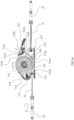
- the safety tensioning device for automobiles in this embodiment mainly comprises a device body 1, a first bundling strap 2 and a second bundling strap 3.
- the device body 1 comprises a base assembly 11, a handle assembly 12, a reel assembly 13 and a handle wheel assembly 14. At least one first bundling strap 2 with or without a hook needs to be connected to the device body 1 for use.
- the first bundling strap 2 comprises a first woven strap 21 which can be rolled and a hook 22.
- the second bundling strap 3 comprises a short second woven strap 31 and a hook 22.
- the base assembly 11 comprises a base 111 having a front end, a rear end, a top and a bottom.
- a housing 118, a support plate 114, a stop plate 112 and a stop plate spring 113 are disposed at the front end of the base 111, and a pressing plate 115 and a pressing plate spring 116 are disposed at the rear end thereof, which are pivoted to the base 111 through a connecting shaft 117.
- the connecting shaft 117 is also used for connecting the second bundling strap 3.
- the stop plate 112 may be of a sliding type or a swinging type, and the stop plate 112 is shown as being of a sliding type in figures.
- the stop plate spring 113 may also be a compressing spring or a torsion spring, and the stop plate spring 113 is shown as a compression spring in figures.
- the handle assembly 12 comprises a handle 121, a driving pawl 122 having a front end and a rear end and a pawl spring 123.
- the driving pawl 122 has a plurality of protruded limiting blocks 122a on two sides of the front end of the driving pawl 122, a button 122b in a middle of the rear end thereof, and a plurality of push blocks 122c on two sides of the rear end thereof.
- recessed operating regions are separated by a plurality of protrusions 111f on the top of the base 111.
- the three operating regions are a tensioning region 111a, a working region 111b and a release region 111c distributed successively from front to back and are used for receiving the limiting block 122a, and different regions have different functions.
- a side the base 111 located at the first bundling strap 2 is the front side, and the other side thereof is the rear side.
- the base 111 is U-shaped, and a support plate 114 is disposed in the front end of the base 111 to fix an opening of the U-shaped base.
- the support plate 114 also plays a role in supporting the stop plate spring 113, and the stop plate 112 slides radially relative to an axis under the action of the spring 113 and tends to the axis.
- Each protruded barb 111d is disposed on each side of the front end of the base 111 and is matched with each notch 118a below the housing 118. After assembling, the both are buckled with each other, so that the housing 118 is not easy to fall off.
- the housing 118 has a groove 118b in a front side of the housing 118.
- the groove 118b is used for restricting and receiving the hook 22 of the first bundling strap 2 and plays a buffering role when the hook 22 is retracted rapidly.
- the groove 118b has a strap passage hole 118c for allowing the first bundling strap 2 to pass through in a middle of the groove 118b.
- the base 111 has a connecting hole 111e which can allow a bolt or rivet to pass through so as to fix the device body 1 at a corresponding position of the automobile or cargo, so that the second bundling strap 3 is not needed, and the device body 1 can operate by only using the first bundling strap 2.
- the connecting shaft 117 is mounted in the rear end of the base 111, and a second first bundling strap 31 is used for connecting the device body 1 to the second bundling strap 3. Meanwhile, the connecting shaft 117 is pivoted to a pressing plate 115 and a pressing plate spring 116. Under the action of the spring force, the pressing plate 115 swings around the connecting shaft 117, urging a front end 115a of the pressing plate 115 against the ratchet wheel 132 to generate pressure to stop the rotation of the reel 131.
- the handle assembly 12 comprises the handle 121, the driving pawl 122 and the pawl spring 123.
- the plurality of protruded limiting blocks 122a is arranged on two sides of the front end of the driving pawl 122
- the button 122b is arranged in the middle of the rear end thereof
- the plurality of push blocks 122c is arranged on two sides of the rear end thereof
- a convex core 122d is arranged in the middle of the driving pawl 122 to serve as a rotation center of the driving pawl 122.
- the pawl spring 123 is sleeved on the convex core 122d.
- the handle 121 has a cavity 121a for receiving the button 122b on a top of the handle 121, a hole 121b for receiving the convex core 122a on each side of the handle 121, a groove 121c for receiving the limiting block 122a, and a hole 121f for receiving a main shaft 135 and a shaft sleeve 134.
- a first bump 121d and a second bump 121e are arranged in the front and rear of a bottom edge of the handle 121 to push the stop plate 112 and the pressing plate 115, respectively.
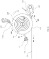
- the reel assembly 13 comprises a reel 131, the main shaft 135, a coil spring 137 and the shaft sleeve 134.
- the reel 131 is a disc shape consisting of two ratchet wheels 132 and a drum 133, and is used for winding the first bundling strap 2.
- the handle assembly 12 and the base assembly 11 are pivoted through the shaft sleeve 134, the handle 121 is located on an inner side of the base 111, and the reel 131 is located in a center of an inner side of the handle 121.
- the main shaft 135 passes through the shaft sleeve 134 and the reel 131 and is restricted by a clamp spring 136.
- the main shaft 135 has a special-shaped section which can be inserted into the special-shaped hole on the ratchet wheel 132, so that the reel 131 can drive the main shaft 135 to rotate together, or the main shaft 135 can drive the reel 131 to rotate together.
- a first end 135a of the main shaft 135 is connected to an inner hook of the coil spring 137, an outer hook of the coil spring 137 is connected to a coil spring box 138, and the coil spring box 138 is fixed on the outer side face of the base 111.
- a second end 135b of the main shaft is connected to a hand wheel assembly 14.
- the hand wheel assembly 14 may adopt many different structures. As shown in the figures in this embodiment, specifically as shown in Figs. 1 , 2 , 3 , 4 , 9 and 10a , the hand wheel assembly 14 comprises a hand wheel 141, a damping elastic member 143 and a screw 144.
- the protruded second end 135b of the main shaft 135 has a special-shaped section which can be inserted into the special-shaped hole in the middle of the hand wheel 141, and the hand wheel 141 is fixed on the main shaft 135 by the screw 144, so that the main shaft 135 can be driven to rotate by rotating the hand wheel 141.
- the damping elastic member 143 is arranged between the hand wheel 141 and the base 111 to increase friction and reduce the speed of the first bundling strap 2 when it is retracted quickly, thereby preventing the hook 22 to rebounding quickly to hurt the operator.
- the damping elastic member may be a compression spring, etc.
- the hand wheel 141 is a common disc-shaped hand wheel.
- this embodiment differs from Embodiment 1 in that, a hand wheel is an impeller-shaped hand wheel.
- the hand wheel 141 is also fixed at the second end 135b of the main shaft 135 by the screw 144.
- the hand wheel 141 has a hand wheel box 142 arranged on a periphery of the hand wheel 141, and the hand wheel box 142 is fixed on the side of the base 111 by the rivet 139.
- Fig. 11 is a schematic diagram of the safety tensioning device for automobiles when the first bundling strap 2 is in a release state.
- the button 112b is pressed down, the handle assembly 12 is rotated.
- the limiting block 122a is restricted in the release region 111c of the base 111, the driving pawl 122 is separated from the ratchet wheel 132, and the stop plate 112 is pushed to separate from the ratchet wheel 132 by the first bump 121d of the handle 112.
- the front end 115a of the pressing plate 115 still presses the ratchet wheel 132 under the action of the spring 116.
- the moment M3 produced by the pressing plate 115 on the reel 131 is greater than the moment M2 produced by the coil spring, that is, M3>M2, so as to prevent the reel 131 from rotating freely.
- the first bundling strap 2 is pulled outward by applying an additional force. At this time, a moment M4 will be produced on the reel 131. If M4>M2, the reel 131 will overcome the pressure caused by the pressing plate 115, and thus rotates in the shown direction. That is, the hook 22 and the first woven strap 21 is pulled out of the device body 1, the hook 22 can be hung on a corresponding securing point on the automobile or cargo according to actual needs.
- Fig. 12 shows the safety tensioning device for automobiles when the first bundling strap 2 is in a tensioned state.
- the button 122b is pressed down, the handle assembly 12 is rotated, the limiting block 122a is restricted in the tensioning region 111a, and the driving pawl 122 is engaged with the ratchet wheel 132.
- the first bump 121d of the handle 121 is rotated to separate from the stop plate 112.
- the stop plate 112 is pushed to a center of the reel 131 and engaged with the ratchet wheel 132.
- the handle assembly 12 is pushed repeatedly to drive the reel 131 to rotate counterclockwise as shown in Fig. 12 , and the first bundling strap 2 is wound into the reel 131, thereby producing tension to realize the tensioning operation of the first bundling strap 2.
- the stop plate 112 prevents the ratchet wheel 132 from reverse rotation, so that the tension is maintained.
- Fig. 13 shows the safety tensioning device for automobiles when in an operating state.
- the button 122a is pressed down, the handle assembly 12 is rotated, and the limiting block 122a is restricted in the working region 111b.
- the driving pawl 122 is separated from the ratchet wheel 132.
- the second bump 121e of the handle 121 pushes the front end 115a of the pressing plate 115 to separate from the ratchet wheel 132.
- only the stop plate 112 is engaged with the ratchet wheel 132 and prevents the ratchet wheel 132 from reverse rotation, thereby maintaining the tension, which means the tension device is in the working state.
- the originally tensioned first woven strap 21 may be loose.
- the moment M1 produced by the stop plate 112 on the reel 131 is less than the moment M2 produced by the coil spring 137 on the main shaft 135, that is, M1 ⁇ M2, under the action of the coil spring 137, the reel 131 overcomes the resistance of the stop plate 112 and rotates counterclockwise to wind the loose first woven strap 21 into the reel 131.
- the button 122b is pressed down, the handle assembly 12 is rotated, and the limiting block 122a is restricted in the release region 111c, as shown in Fig. 11 .
- both the driving pawl 122 and the stop plate 112 are separated from the ratchet wheel 132 to release the tension on the first woven 21.
- the front end 115a of the pressing plate 115 rotates under the action of the spring 116 and presses on the ratchet wheel 132, so that the reel 131 is prevented from counterclockwise rotation under the action of the coil spring 137, and the first bundling strap 2 with the hook 22 is prevented from rapidly rebounding to hurt the operator.
- M1 is the torque produced during a process of preventing the counterclockwise rotation (winding) of the reel 131, and the force comes from the spring 113.
- M2 is the torque produced by the energy-stored coil spring 137 when acting on the main shaft 135, and this torque can drive the reel 131 to rotate counterclockwise (winding).
- M3 is the torque which is produced by the pressing plate 115 when pressing the ratchet wheel 132 under the action of the spring 116 and can prevent the counterclockwise rotation (winding) and clockwise rotation (unwinding) of the reel 131.
- the three torques (called passive torques) are produced by the elastic force of the elastic member arranged at the corresponding position.
- M4 is the torque produced on the reel 131 by an external force when the first woven strap 21 is pulled out by the hand, and is only used for pulling out the first woven strap 21 or adjusting a length of the first woven strap 21 in the early stage of operation.
- M5 is the torque (called an active torque) produced by an external force when pushing the handle 122 and the ratchet wheel 132 to drive the reel 131, and is only used for the tensioning operation.
- a magnitude of the active torque depends on a magnitude of the applied external force
- a magnitude of the passive torque depends on a magnitude of the elastic force of the corresponding elastic member.
- the magnitude of the three passive torques is defined as follows: M1 ⁇ M2 ⁇ M3.
- both the driving pawl 122 and the pressing plate 115 are separated from the ratchet wheel 132. Since M1 ⁇ M2, the coil spring 137 can drive the main shaft 135 and the reel to rotate counterclockwise so as to wind the first bundling strap 2.
- both the driving pawl 122 and the stop plate 112 are separated from the ratchet wheel 132. Since M2 ⁇ M3, the ratchet wheel 132 still cannot rotate. At this time, if a corresponding force is applied to the first woven strap 21 to allow M4>M3, the reel 131 overcomes the pressure from the pressing plate 115 to rotate clockwise, so that the first woven strap 21 is pulled out. Or, the button 122b is pressed down to push the pressing plate 115 to separate from the ratchet wheel 132. The reel 131 rotates counterclockwise only under the torque M2, so that the first bundling strap 21 can be quickly retracted into the reel 131.
Landscapes
- Engineering & Computer Science (AREA)
- Mechanical Engineering (AREA)
- Transportation (AREA)
- Aviation & Aerospace Engineering (AREA)
- Chemical & Material Sciences (AREA)
- Combustion & Propulsion (AREA)
- Ocean & Marine Engineering (AREA)
- Package Frames And Binding Bands (AREA)
- Automotive Seat Belt Assembly (AREA)
Abstract
Description
- The present invention relates to a safety tensioning device for automobiles which is used for fixing and fastening cargos on vehicles such as automobiles, trailers, airplanes and ships.
- The safety tensioning device for automobiles usually consists of a tensioning device body, a long bundling strap, a short bundling strap or the like. The bundling straps are generally woven straps with or without hooks. The device body employs an anti-reverse rotation ratchet mechanism. A driving pawl is driven directly by a handle, the driving pawl pushes a ratchet wheel, and the ratchet wheel directly drives a main shaft, so that a bundling strap wound onto the main shaft is tensioned. A stop plate prevents the ratchet wheel from reverse rotation, so that certain tension can be maintained on the bundling strap and the cargo can be tied up and fixed. The length of a working area of the device will be different according to different application scenarios, so the excessive bundling straps will always fly outside the device, resulting in potential safety hazards; and, the bundling strap is very messy after use, thus affecting the latter use.
- Products for automatically winding the bundling strap are available in a market. For example, a Chinese patent
CN100391645C (patent No.:CN200610050653.6 - In addition, after use, the first bundling strap should be able to be automatically wound into the reel. However, after long-term use, the volute spiral spring that produces the driving force will have the attenuation of elasticity or even break and lose its elasticity, so that the first bundling strap cannot be completely wound or automatically wound.
- In summary, it is necessary to further improve the existing safety tensioning devices for automobiles.
- A first technical problem to be solved by the present invention is to provide a safety tensioning device for automobiles which can automatically wind a first bundling strap when the first bundling strap is loose during use, so that the first bundling strap of the tensioning device in an operating state can always keep tensioned, thus preventing unhooking and improving safety.
- A second technical problem to be solved by the present invention is to provide a safety tensioning device for automobiles which can still completely wind a first bundling strap into a reel after the elasticity of a volute spiral spring is attenuated or disabled.
- To solve the first technical problem, the safety tensioning device for automobiles comprises a base having a front end, a rear end, a top and a bottom; a handle; a first bundling strap having a first bundling strap and a hook; a winding assembly disposed on the base and driven by a main shaft, the winding assembly having a reel for winding the first bundling strap using a ratchet wheel and a coil spring; a stop plate and a pressing plate disposed respectively at the front end and the rear end of the base; a driving pawl having one or more limiting blocks is rotatably connected to the handle; wherein, the handle is pivoted to the base and is capable of rotating about the main shaft, the rotation of the handle changes an acting state of the stop plate and the pressing plate to the ratchet wheel; the base has three operating regions on the top of the base: a tensioning region, a working region and a release region, the three operating regions cooperate with the limiting block of the driving pawl; when the limiting block of the driving pawl is restricted to the working region, both the driving pawl and the pressing plate are separated from the ratchet wheel, the stop plate is engaged with the ratchet wheel, and, a moment M1 produced by the stop plate on the reel is less than a moment M2 produced by the coil spring on the main shaft, that is, M1< M2, so as to tension the loose first bundling strap on the reel by the coil spring.
- Thus, in an operating state, when the first bundling strap is loose, for example, at a moment of jolts, the ratchet wheel can rotate counterclockwise under the action of the coil spring so as to push the stop plate. After passing across one or more teeth, the stop plate engages a rood of the racket wheel again.
- In the tensioning device with the above structure, preferably, the handle has a first bump and a second bump on a bottom of the handle for respectively pushing the stop plate and the pressing plate, the handle can push the stop plate and the pressing plate during rotation of the handle, so as to engage or disengage the stop plate with the ratchet wheel, and attach or separate the pressing plate from the ratchet wheel, to change the acting state of the stop plate and the pressing plate to the ratchet wheel.
- Preferably, the driving pawl has a push block at a rear end of the driving pawl for pushing the pressing plate to rotate and separate from the ratchet wheel. Conventionally, the stop plate functions to prevent the ratchet wheel from reverse rotation, and the pressing plate functions to control a rotation speed of the ratchet wheel, wherein the forward rotation of the ratchet wheel (a counterclockwise direction shown in the figures) means the first bundling strap is in a tensioned state, while the reverse rotation of the ratchet wheel (a clockwise direction shown in the figures) means the first bundling strap is in a release state.
- In the tensioning device with the above structure, preferably, the base has a plurality of protrusions on the top of a side of the base to separate the tensioning region, working region and release region, the tensioning region, the working region and the release region are distributed sequentially from front to rear of the base. When the limiting blocks on the driving pawl are restricted in the tensioning region, both the driving pawl and the stop plate engage the ratchet wheel, so that a tensioning operation can be realized by operating the handle, that is, the ratchet wheel can be rotated to wind and tension the first bundling strap so as to produce the tension force.
- Preferably, when the limiting block of the driving pawl is restricted to the release region, both the driving pawl and the stop plate are separated from the ratchet wheel, the pressing plate is attached to the ratchet wheel, and, a moment M3 produced by the pressing plate on the reel is greater than the moment M2 produced by the coil spring on the main shaft, that is, M3>M2, so as to prevent the reel from rotating freely. After a button is pressed down to push the pressing plate through the push block, the ratchet wheel can rotate freely to wind the first bundling strap.
- In the tensioning device with the above structure, preferably, a housing covers the front end of the base, a notch and a barb which can be buckled with each other are arranged on the housing and the base, respectively, and, the housing has a groove for receiving the hook of the first bundling strap in a front side of the housing to play a buffer role when the hook is quickly retracted.
- Preferably, the base has a connecting hole, and the base can be fixed at a corresponding position of the automobile or cargo through a connecting member (e.g., a bolt, a rivet, etc.), so that a second bundling strap is not needed.
- To solve the second technical problem, preferably, a hand wheel assembly capable of manually winding the first bundling strap is connected to the main shaft opposite the coil spring, and the hand wheel assembly comprises a hand wheel capable of driving the main shaft to rotate. The hand wheel directly drives the main shaft to rotate and also drives the reel to rotate to wind the first bundling strap, so that complementary winding can be realized when the first bundling strap cannot be automatically retracted completely.
- The main shaft may be separate from or integrated with the hand wheel. If the main shaft is separate from d the hand wheel, the both may be matched with each other through a special-shaped head and a special-shaped hole and then connected and fixed by a screw.
- Preferably, the hand wheel assembly further comprises a damping elastic member which can reduce rotational speed of the main shaft when a winding speed of the first bundling strap is too fast. The damping elastic member may be a compression spring or the like, and is arranged between the hand wheel and the base, to increase the fractional damping between the main shaft and the base, thereby reducing the winding speed and prevent the barbs from rebounding quickly to hurt the operator.
- The hand wheel may be in different shapes, such as a disc-shaped hand wheel or an impeller-shaped hand wheel, when the hand wheel is an impeller-shaped hand wheel, a hand wheel box connected to the base is disposed on a periphery of the hand wheel, thereby preventing the quickly rotating hand wheel from attaching the operator's hand during automatic winding.
- Compared with the prior art, the present invention has the following advantages. In the safety tensioning device for automobiles of the present invention, since the moment M1 produced by the stop plate on the reel is less than the moment M2 produced by the coil spring on the main shaft in the operating state, the reel can automatically wind the first bundling strap. Therefore, the safety tensioning device for automobiles of the present invention can automatically wind the first bundling strap in the release state, and can also automatically wind the first bundling strap when the first bundling strap is loose due to jolts in the operating state, so that the first bundling strap is always kept in the tensioned state, thereby preventing unhooking and greatly improving the use safety. Moreover, when the coil spring is failed, the first bundling strap can be wound by the hand wheel, and the retraction speed can be controlled by the damping elastic member, thereby avoiding an occurrence of accidents of hurting the operator or other persons due to a rebounding of the hook of the first bundling strap during the strap retraction process.
-
-
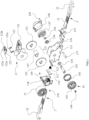
Fig. 1 is an exploded view of a safety tensioning device for automobiles according to Embodiment 1 of the present invention; -
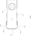
Fig. 2 is a perspective view of the safety tensioning device for automobiles according toEmbodiment 1 of the present invention; -
Fig. 3 is a front view of the safety tensioning device for automobiles according toEmbodiment 1 of the present invention; -
Fig. 4 is a top view of the safety tensioning device for automobiles according to Embodiment 1 of the present invention; -
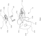
Fig. 5 is an exploded view of a base assembly according toEmbodiment 1 of the present invention; -
Fig. 6 is a sectional view of the base and the housing according toEmbodiment 1 of the present invention; -
Fig. 7 is a sectional view of the safety tensioning device when a hook of a first bundling strap is completely retracted according toEmbodiment 1 of the present invention; -
Fig. 8 is an exploded view of a hand wheel assembly according toEmbodiment 1 of the present invention; -
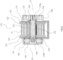
Fig. 9 is a sectional view of the safety tensioning device along the axis of the main shaft according toEmbodiment 1 of the present invention; -
Fig. 10a is a perspective view of the hand wheel assembly according toEmbodiment 1 of the present invention; -
Fig. 10b is a perspective view of the hand wheel assembly according toEmbodiment 2 of the present invention; -
Fig. 10c is a front view of a safety tensioning device according toEmbodiment 2 of the present invention; -
Fig. 11 is a sectional view of the safety tensioning device when the first bundling strap is in a release state according toEmbodiment 1 of the present invention; -
Fig. 12 is a sectional view of the safety tensioning device when the first bundling strap is in a tensioned state according toEmbodiment 1 of the present invention; -
Fig. 13 is a sectional view of the safety tensioning device when in an operating state according toEmbodiment 1 of the present invention; -
Fig. 14 is a sectional view of the safety tensioning device when the first bundling strap is in an automatic winding state according toEmbodiment 1 of the present invention; -
Fig. 15 is a schematic view of a torque of the present invention. - The reference numbers and the corresponding names of components are listed as below:
1: device body; 11: base assembly; 111: base; 111a: tensioning region; 11b: working region; 111c: release region; 111d: barb; 111f: protrusion; 111e: connecting hole; 112: stop plate; 113: stop plate spring; 114: support plate; 115: pressing plate; 115a: front end of the pressing plate; 115b: rear end of the pressing plate; 116: pressing plate spring; 117: connecting shaft; 118: housing; 118a: notch; 118b: groove; 118c: strap passage hole; 12: handle assembly; 121: handle; 121a: cavity; 121b: hole; 121c: groove; 121d: first bump; 121e: second bump; 121f: hole; 122: driving pawl; 122a: limiting block; 122b: button; 122c: push block; 122d: convex core; 123: pawl spring; 13: reel assembly; 131: reel; 132: ratchet wheel; 133: drum; 134: shaft sleeve; 135: main shaft; 135a: first end; 135b: second end; 136: clamp spring; 137: coil spring; 138: coil spring box; 139: rivet; 14: hand wheel assembly; 141: hand wheel; 142: hand wheel box; 143: damping spring; 144: screw; 2: first bundling strap; 21: first woven strap; 22; hook; 3: second bundling strap; and, 31: second woven strap. - The present invention will be further described below in detail by embodiments with reference to the accompanying drawings.
- As shown in
Figs. 1-4 , the safety tensioning device for automobiles in this embodiment mainly comprises adevice body 1, afirst bundling strap 2 and asecond bundling strap 3. - The
device body 1 comprises abase assembly 11, ahandle assembly 12, areel assembly 13 and ahandle wheel assembly 14. At least onefirst bundling strap 2 with or without a hook needs to be connected to thedevice body 1 for use. Preferably, thefirst bundling strap 2 comprises a first wovenstrap 21 which can be rolled and ahook 22. Thesecond bundling strap 3 comprises a short secondwoven strap 31 and ahook 22. - The
base assembly 11 comprises a base 111 having a front end, a rear end, a top and a bottom. Ahousing 118, asupport plate 114, astop plate 112 and astop plate spring 113 are disposed at the front end of thebase 111, and apressing plate 115 and apressing plate spring 116 are disposed at the rear end thereof, which are pivoted to the base 111 through a connectingshaft 117. The connectingshaft 117 is also used for connecting thesecond bundling strap 3. Thestop plate 112 may be of a sliding type or a swinging type, and thestop plate 112 is shown as being of a sliding type in figures. Thestop plate spring 113 may also be a compressing spring or a torsion spring, and thestop plate spring 113 is shown as a compression spring in figures. - The
handle assembly 12 comprises ahandle 121, a drivingpawl 122 having a front end and a rear end and apawl spring 123. The drivingpawl 122 has a plurality of protruded limitingblocks 122a on two sides of the front end of the drivingpawl 122, abutton 122b in a middle of the rear end thereof, and a plurality of push blocks 122c on two sides of the rear end thereof. - As shown in
Fig. 5 , three recessed operating regions are separated by a plurality ofprotrusions 111f on the top of thebase 111. The three operating regions are atensioning region 111a, a workingregion 111b and arelease region 111c distributed successively from front to back and are used for receiving the limitingblock 122a, and different regions have different functions. Herein, a side the base 111 located at thefirst bundling strap 2 is the front side, and the other side thereof is the rear side. - As shown in
Figs. 5 ,6 and7 , thebase 111 is U-shaped, and asupport plate 114 is disposed in the front end of the base 111 to fix an opening of the U-shaped base. Thesupport plate 114 also plays a role in supporting thestop plate spring 113, and thestop plate 112 slides radially relative to an axis under the action of thespring 113 and tends to the axis. Each protrudedbarb 111d is disposed on each side of the front end of thebase 111 and is matched with eachnotch 118a below thehousing 118. After assembling, the both are buckled with each other, so that thehousing 118 is not easy to fall off. Two sides of an upper portion of thehousing 118 are also fixed to thebase 111 by a plurality ofrivets 139. Thehousing 118 has agroove 118b in a front side of thehousing 118. Thegroove 118b is used for restricting and receiving thehook 22 of thefirst bundling strap 2 and plays a buffering role when thehook 22 is retracted rapidly. Thegroove 118b has astrap passage hole 118c for allowing thefirst bundling strap 2 to pass through in a middle of thegroove 118b. - The
base 111 has a connectinghole 111e which can allow a bolt or rivet to pass through so as to fix thedevice body 1 at a corresponding position of the automobile or cargo, so that thesecond bundling strap 3 is not needed, and thedevice body 1 can operate by only using thefirst bundling strap 2. - The connecting
shaft 117 is mounted in the rear end of thebase 111, and a secondfirst bundling strap 31 is used for connecting thedevice body 1 to thesecond bundling strap 3. Meanwhile, the connectingshaft 117 is pivoted to apressing plate 115 and apressing plate spring 116. Under the action of the spring force, thepressing plate 115 swings around the connectingshaft 117, urging afront end 115a of thepressing plate 115 against theratchet wheel 132 to generate pressure to stop the rotation of thereel 131. - As shown in
Fig. 8 , thehandle assembly 12 comprises thehandle 121, the drivingpawl 122 and thepawl spring 123. The plurality of protruded limitingblocks 122a is arranged on two sides of the front end of the drivingpawl 122, thebutton 122b is arranged in the middle of the rear end thereof, the plurality ofpush blocks 122c is arranged on two sides of the rear end thereof, and aconvex core 122d is arranged in the middle of the drivingpawl 122 to serve as a rotation center of the drivingpawl 122. Thepawl spring 123 is sleeved on theconvex core 122d. Thehandle 121 has acavity 121a for receiving thebutton 122b on a top of thehandle 121, ahole 121b for receiving theconvex core 122a on each side of thehandle 121, agroove 121c for receiving the limitingblock 122a, and ahole 121f for receiving amain shaft 135 and ashaft sleeve 134. Afirst bump 121d and asecond bump 121e are arranged in the front and rear of a bottom edge of thehandle 121 to push thestop plate 112 and thepressing plate 115, respectively. - As shown in
Fig. 9 , thereel assembly 13 comprises areel 131, themain shaft 135, acoil spring 137 and theshaft sleeve 134. Thereel 131 is a disc shape consisting of tworatchet wheels 132 and adrum 133, and is used for winding thefirst bundling strap 2. Thehandle assembly 12 and thebase assembly 11 are pivoted through theshaft sleeve 134, thehandle 121 is located on an inner side of thebase 111, and thereel 131 is located in a center of an inner side of thehandle 121. Themain shaft 135 passes through theshaft sleeve 134 and thereel 131 and is restricted by aclamp spring 136. Themain shaft 135 has a special-shaped section which can be inserted into the special-shaped hole on theratchet wheel 132, so that thereel 131 can drive themain shaft 135 to rotate together, or themain shaft 135 can drive thereel 131 to rotate together. Afirst end 135a of themain shaft 135 is connected to an inner hook of thecoil spring 137, an outer hook of thecoil spring 137 is connected to acoil spring box 138, and thecoil spring box 138 is fixed on the outer side face of thebase 111. Asecond end 135b of the main shaft is connected to ahand wheel assembly 14. - The
hand wheel assembly 14 may adopt many different structures. As shown in the figures in this embodiment, specifically as shown inFigs. 1 ,2 ,3 ,4 ,9 and10a , thehand wheel assembly 14 comprises ahand wheel 141, a dampingelastic member 143 and ascrew 144. The protrudedsecond end 135b of themain shaft 135 has a special-shaped section which can be inserted into the special-shaped hole in the middle of thehand wheel 141, and thehand wheel 141 is fixed on themain shaft 135 by thescrew 144, so that themain shaft 135 can be driven to rotate by rotating thehand wheel 141. The dampingelastic member 143 is arranged between thehand wheel 141 and the base 111 to increase friction and reduce the speed of thefirst bundling strap 2 when it is retracted quickly, thereby preventing thehook 22 to rebounding quickly to hurt the operator. The damping elastic member may be a compression spring, etc. Thehand wheel 141 is a common disc-shaped hand wheel. - As shown in
Figs. 10b and10c , this embodiment differs fromEmbodiment 1 in that, a hand wheel is an impeller-shaped hand wheel. Thehand wheel 141 is also fixed at thesecond end 135b of themain shaft 135 by thescrew 144. To prevent thehand wheel 141 from attaching the operator's hand during its fast rotation, thehand wheel 141 has ahand wheel box 142 arranged on a periphery of thehand wheel 141, and thehand wheel box 142 is fixed on the side of the base 111 by therivet 139. - The dynamic process of the tensioning device when in use will be described below with reference to the figures.
-
Fig. 11 is a schematic diagram of the safety tensioning device for automobiles when thefirst bundling strap 2 is in a release state. The button 112b is pressed down, thehandle assembly 12 is rotated. When the limitingblock 122a is restricted in therelease region 111c of thebase 111, the drivingpawl 122 is separated from theratchet wheel 132, and thestop plate 112 is pushed to separate from theratchet wheel 132 by thefirst bump 121d of thehandle 112. In this state, thefront end 115a of thepressing plate 115 still presses theratchet wheel 132 under the action of thespring 116. The moment M3 produced by thepressing plate 115 on thereel 131 is greater than the moment M2 produced by the coil spring, that is, M3>M2, so as to prevent thereel 131 from rotating freely. - The
first bundling strap 2 is pulled outward by applying an additional force. At this time, a moment M4 will be produced on thereel 131. If M4>M2, thereel 131 will overcome the pressure caused by thepressing plate 115, and thus rotates in the shown direction. That is, thehook 22 and the first wovenstrap 21 is pulled out of thedevice body 1, thehook 22 can be hung on a corresponding securing point on the automobile or cargo according to actual needs. -
Fig. 12 shows the safety tensioning device for automobiles when thefirst bundling strap 2 is in a tensioned state. After thehook 22 is hung on the corresponding securing point, thebutton 122b is pressed down, thehandle assembly 12 is rotated, the limitingblock 122a is restricted in thetensioning region 111a, and the drivingpawl 122 is engaged with theratchet wheel 132. At this time, thefirst bump 121d of thehandle 121 is rotated to separate from thestop plate 112. Under the action of thespring 113, thestop plate 112 is pushed to a center of thereel 131 and engaged with theratchet wheel 132. Thehandle assembly 12 is pushed repeatedly to drive thereel 131 to rotate counterclockwise as shown inFig. 12 , and thefirst bundling strap 2 is wound into thereel 131, thereby producing tension to realize the tensioning operation of thefirst bundling strap 2. Thestop plate 112 prevents theratchet wheel 132 from reverse rotation, so that the tension is maintained. -
Fig. 13 shows the safety tensioning device for automobiles when in an operating state. After the tensioning operation is completed, thebutton 122a is pressed down, thehandle assembly 12 is rotated, and the limitingblock 122a is restricted in the workingregion 111b. At this time, the drivingpawl 122 is separated from theratchet wheel 132. Meanwhile, thesecond bump 121e of thehandle 121 pushes thefront end 115a of thepressing plate 115 to separate from theratchet wheel 132. At this time, only thestop plate 112 is engaged with theratchet wheel 132 and prevents theratchet wheel 132 from reverse rotation, thereby maintaining the tension, which means the tension device is in the working state. - In the operating state of the safety tensioning device for automobiles, in case of jolts, vibration, cargo slippage or the like, the originally tensioned first woven
strap 21 may be loose. At this time, since the moment M1 produced by thestop plate 112 on thereel 131 is less than the moment M2 produced by thecoil spring 137 on themain shaft 135, that is, M1<M2, under the action of thecoil spring 137, thereel 131 overcomes the resistance of thestop plate 112 and rotates counterclockwise to wind the loose firstwoven strap 21 into thereel 131. - After use, the
button 122b is pressed down, thehandle assembly 12 is rotated, and the limitingblock 122a is restricted in therelease region 111c, as shown inFig. 11 . At this time, both the drivingpawl 122 and thestop plate 112 are separated from theratchet wheel 132 to release the tension on the first woven 21. Meanwhile, when thesecond bump 121e of thehandle 121 is separated from thefront end 115a of the pressing plate, thefront end 115a of thepressing plate 115 rotates under the action of thespring 116 and presses on theratchet wheel 132, so that thereel 131 is prevented from counterclockwise rotation under the action of thecoil spring 137, and thefirst bundling strap 2 with thehook 22 is prevented from rapidly rebounding to hurt the operator. - As shown in
Fig. 14 , if the first wovenstrap 21 and thehook 22 are continuously retracted, it is only necessary to press down thebutton 122b on the drivingpawl 122 again, thepush block 122c at the rear end of the drivingpawl 122 come into contact with therear end 115b of thepressing plate 115 and pushes thepressing plate 115 to rotate, so that thefront end 115a of thepressing plate 115 is separated from theratchet wheel 132. At this time, thereel 131 rotates counterclockwise under the action of thecoil spring 137 to wind thefirst bundling strap 2 into thereel 131. - The related torque on the
reel 131 will be further explained, as shown inFig. 15 , where M1 is the torque produced during a process of preventing the counterclockwise rotation (winding) of thereel 131, and the force comes from thespring 113. M2 is the torque produced by the energy-storedcoil spring 137 when acting on themain shaft 135, and this torque can drive thereel 131 to rotate counterclockwise (winding). M3 is the torque which is produced by thepressing plate 115 when pressing theratchet wheel 132 under the action of thespring 116 and can prevent the counterclockwise rotation (winding) and clockwise rotation (unwinding) of thereel 131. The three torques (called passive torques) are produced by the elastic force of the elastic member arranged at the corresponding position. M4 is the torque produced on thereel 131 by an external force when the first wovenstrap 21 is pulled out by the hand, and is only used for pulling out the first wovenstrap 21 or adjusting a length of the first wovenstrap 21 in the early stage of operation. M5 is the torque (called an active torque) produced by an external force when pushing thehandle 122 and theratchet wheel 132 to drive thereel 131, and is only used for the tensioning operation. - When the
reel 131 is in a same diameter and size, a magnitude of the active torque depends on a magnitude of the applied external force, and a magnitude of the passive torque depends on a magnitude of the elastic force of the corresponding elastic member. - To achieve the functional effect of the present invention, the magnitude of the three passive torques is defined as follows: M1<M2<M3.
- When the limiting
block 122a on the drivingpawl 122 is restricted in the workingregion 111b, both the drivingpawl 122 and thepressing plate 115 are separated from theratchet wheel 132. Since M1<M2, thecoil spring 137 can drive themain shaft 135 and the reel to rotate counterclockwise so as to wind thefirst bundling strap 2. - When the limiting
block 122a on the drivingpawl 122 is restricted in therelease region 111a, both the drivingpawl 122 and thestop plate 112 are separated from theratchet wheel 132. Since M2<M3, theratchet wheel 132 still cannot rotate. At this time, if a corresponding force is applied to the first wovenstrap 21 to allow M4>M3, thereel 131 overcomes the pressure from thepressing plate 115 to rotate clockwise, so that the first wovenstrap 21 is pulled out. Or, thebutton 122b is pressed down to push thepressing plate 115 to separate from theratchet wheel 132. Thereel 131 rotates counterclockwise only under the torque M2, so that thefirst bundling strap 21 can be quickly retracted into thereel 131. - It is inevitable that the elasticity of the
coil spring 137 will be attenuated to a certain extent after a period of time so that the first wovenstrap 21 cannot be retracted completely. It is also possible that thecoil spring 137 will break and unhook after long-term use or under other unexpected circumstances, resulting in the complete failure of the automatic winding function. At this time, it is only necessary to rotate thehand wheel 141 counterclockwise to drive themain shaft 135 and thereel 131 to rotate, so that the first wovenstrap 21 and thehook 22 are completely retracted manually.
Claims (11)
- A safety tensioning device for automobiles, comprising:a base (111) having a front end, a rear end, a top and a bottom;a handle (121);a first bundling strap (2) having a first bundling strap (21) and a hook (22);a winding assembly (13) disposed on the base (111) and driven by a main shaft (135), the winding assembly (13) having a reel (131) for winding the first bundling strap (2) using a ratchet wheel (132) and a coil spring (137);a stop plate (112) and a pressing plate (115) disposed respectively at the front end and the rear end of the base (111);a driving pawl (122) having one or more limiting blocks (122a) is rotatably connected to the handle (121);characterized in that,the handle (121) is pivoted to the base (111) and is capable of rotating about the main shaft (135), the rotation of the handle (121) changes an acting state of the stop plate (111) and the pressing plate (115) to the ratchet wheel (132);the base (111) has three operating regions on the top of the base (111): a tensioning region (111a), a working region (111b) and a release region (111c), the three operating regions cooperate with the limiting block (122a) of the driving pawl (122);when the limiting block (122a) of the driving pawl (122) is restricted to the working region (111b), both the driving pawl (122) and the pressing plate (115) are separated from the ratchet wheel (132), the stop plate (112) is engaged with the ratchet wheel (132), and, a moment M1 produced by the stop plate (112) on the reel (131) is less than a moment M2 produced by the coil spring (137) on the main shaft (135) so as to tension the loose first bundling strap (2) on the reel (131) by the coil spring (137).
- The safety tensioning device according to claim 1, characterized in that the handle (121) has a first bump (121d) and a second bump (121e) on a bottom of the handle (121) for respectively pushing the stop plate (112) and the pressing plate (115), the handle (121) can push the stop plate (112) and the pressing plate (115) during rotation of the handle (121), so as to engage or disengage the stop plate (112) with the ratchet wheel (132), and attach or separate the pressing plate (115) from the ratchet wheel (132), to change the acting state of the stop plate (111) and the pressing plate (115) to the ratchet wheel (132).
- The safety tensioning device according to claim 1, characterized in that the driving pawl (122) has a push block (122c) at a rear end of the driving pawl (122) for pushing the pressing plate (115) to rotate and separate from the ratchet wheel (132).
- The safety tensioning device according to claim 1, characterized in that the base (111) has a plurality of protrusions (111f) on the top of the base (111) to separate the tensioning region (111a), working region (111b) and release region (111c), the tensioning region (111a), the working region (111b) and the release region (111c) are distributed sequentially from front to rear of the base (111).
- The safety tensioning device according to claim 1, characterized in that when the limiting block (122a) of the driving pawl (122) is restricted to the release region (111c), both the driving pawl (122) and the stop plate (112) are separated from the ratchet wheel (132), the pressing plate (115) is attached to the ratchet wheel (132), and, a moment M3 produced by the pressing plate (115) on the reel (131) is greater than the moment M2 produced by the coil spring (137) on the main shaft (135), so as to prevent the reel (131) from rotating freely.
- The safety tensioning device according to claim 1, characterized in that a housing (118) covers the front end of the base (111), a notch (118a) and a barb (111d) which can be buckled with each other are arranged on the housing (118) and the base (111), respectively, and, the housing (118) has a groove (118b) for receiving the hook (22) of the first bundling strap (2) in a front side of the housing (118).
- The safety tensioning device according to claim 1, characterized in that the base (111) has a connecting hole (111e).
- The safety tensioning device according to any one of claims 1-7, characterized in that a hand wheel assembly (14) capable of manually winding the first bundling strap (2) is connected to the main shaft (135) opposite the coil spring (137), and the hand wheel assembly (14) comprises a hand wheel (141) capable of driving the main shaft (135) to rotate.
- The safety tensioning device according to claim 8, characterized in that the hand wheel assembly (14) further comprises a damping elastic member (143) which can reduce rotational speed of the main shaft (135).
- The safety tensioning device according to claim 8, characterized in that the hand wheel (141) is a disc-shaped hand wheel or an impeller-shaped hand wheel, when the hand wheel (141) is an impeller-shaped hand wheel, a hand wheel box (142) connected to the base (111) is disposed on a periphery of the hand wheel (141).
- The safety tensioning device according to claim 1, characterized in that when the limiting block (122a) of the driving pawl is restricted in the tensioning region (111a), both the driving pawl (122) and the stop plate (112) are engaged with the ratchet wheel (132).
Applications Claiming Priority (1)
| Application Number | Priority Date | Filing Date | Title |
|---|---|---|---|
| CN202310937459.3A CN116968618B (en) | 2023-07-28 | 2023-07-28 | Automobile safety tension device |
Publications (2)
| Publication Number | Publication Date |
|---|---|
| EP4497632A1 true EP4497632A1 (en) | 2025-01-29 |
| EP4497632B1 EP4497632B1 (en) | 2026-02-18 |
Family
ID=88484514
Family Applications (1)
| Application Number | Title | Priority Date | Filing Date |
|---|---|---|---|
| EP24154160.6A Active EP4497632B1 (en) | 2023-07-28 | 2024-01-26 | Safety tensioning device for automobiles |
Country Status (5)
| Country | Link |
|---|---|
| US (1) | US12508975B2 (en) |
| EP (1) | EP4497632B1 (en) |
| CN (1) | CN116968618B (en) |
| AU (1) | AU2024200451B2 (en) |
| CA (1) | CA3227025A1 (en) |
Families Citing this family (4)
| Publication number | Priority date | Publication date | Assignee | Title |
|---|---|---|---|---|
| CN116692245B (en) * | 2023-07-18 | 2025-12-26 | 泰州润杰物流安全装备科技有限公司 | An inertial centrifugal force controlled safety belt tensioning device |
| CN221214737U (en) * | 2023-12-06 | 2024-06-25 | 宁波市裕霖进出口有限公司 | A safety ratchet strap tensioner |
| US12495869B1 (en) * | 2024-12-06 | 2025-12-16 | Ningbo Xuding Rigging Co., Ltd | Anti-jamming ratchet-type tensioning device |
| US20260068999A1 (en) * | 2025-11-13 | 2026-03-12 | Zhangjiagang SMK MFG. Co., Ltd | Automatic Strap Retractor Tensioner |
Citations (4)
| Publication number | Priority date | Publication date | Assignee | Title |
|---|---|---|---|---|
| CN100391645C (en) | 2006-05-09 | 2008-06-04 | 宁波旭力金属制品有限公司 | Automatic belt tensioning machine |
| DE102009031518A1 (en) * | 2009-07-02 | 2011-01-05 | Han-Ching Huang | Belt tensioning arrangement, has locking element engaged to contact section and disengaged from wheel and locking device pressed for disengagement from wheel for rotation of wheel, where wheel is selectively impinged by brake mechanism |
| US20130036580A1 (en) * | 2011-08-09 | 2013-02-14 | Han-Ching Huang | Strap-Tensioning Apparatus |
| US20200238888A1 (en) * | 2018-02-20 | 2020-07-30 | Wesley Zhou | Tie down with automatic strap tension adjustment |
Family Cites Families (18)
| Publication number | Priority date | Publication date | Assignee | Title |
|---|---|---|---|---|
| US2586048A (en) * | 1946-03-30 | 1952-02-19 | Auld D L Co | Cable tightening and reeling apparatus |
| CA2040850C (en) * | 1990-05-03 | 1995-09-19 | Hans-Werner Kamper | Tensioning assembly for the stepwise tightening and releasing of a tensioning strap |
| DE9102777U1 (en) * | 1991-03-08 | 1992-07-02 | Spanset Inter Ag, Oetwil Am See | Tensioning and lashing device for lashing ropes |
| US7350767B2 (en) * | 2005-03-03 | 2008-04-01 | Han-Ching Huang | Strapping apparatus |
| US7789603B2 (en) * | 2007-07-20 | 2010-09-07 | Indiana Mills & Manufacturing, Inc. | Retractable tie down device |
| US8312601B2 (en) * | 2010-01-22 | 2012-11-20 | Han-Ching Huang | Strap-tightening device |
| CN102275539B (en) * | 2011-06-02 | 2013-04-24 | 宁波旭力金属制品有限公司 | Multi-stage transmission automobile safety tension device |
| DE202011050983U1 (en) * | 2011-08-12 | 2011-11-23 | Han-Ching Huang | Device for tensioning a band |
| US8905379B2 (en) * | 2013-03-02 | 2014-12-09 | Han-Ching Huang | Tie-down device |
| US10227030B2 (en) * | 2015-06-01 | 2019-03-12 | Kenneth G. Kingery | Ratchet configurations |
| CN105235933A (en) * | 2015-10-31 | 2016-01-13 | 江苏润阳信息产业有限公司 | Automatic tightening device with rolling and unrolling control function |
| CN106274641A (en) * | 2016-10-31 | 2017-01-04 | 宁波旭力金属制品有限公司 | A kind of automatic band-retracting vehicle safety tensioning device |
| US10065554B1 (en) * | 2017-03-24 | 2018-09-04 | Juefang Xia | Adjustable ratchet tie down |
| DE202019102243U1 (en) * | 2019-04-18 | 2019-04-26 | Wesley Zhou | Clamping device with automatic belt tension regulation |
| CN110816392B (en) * | 2019-12-06 | 2024-11-05 | 宁波旭力金属制品有限公司 | Automobile safety tensioning device |
| CN110950194B (en) * | 2019-12-16 | 2024-10-25 | 泰州润杰物流安全装备科技有限公司 | A safety control belt tightening device |
| CN112248916B (en) * | 2020-11-20 | 2024-11-05 | 宁波旭力金属制品有限公司 | Slow-speed belt-retracting vehicle safety tensioning device |
| CN220518127U (en) * | 2023-07-28 | 2024-02-23 | 宁波旭力金属制品有限公司 | car safety tensioning device |
-
2023
- 2023-07-28 CN CN202310937459.3A patent/CN116968618B/en active Active
-
2024
- 2024-01-19 US US18/417,208 patent/US12508975B2/en active Active
- 2024-01-24 AU AU2024200451A patent/AU2024200451B2/en active Active
- 2024-01-24 CA CA3227025A patent/CA3227025A1/en active Pending
- 2024-01-26 EP EP24154160.6A patent/EP4497632B1/en active Active
Patent Citations (4)
| Publication number | Priority date | Publication date | Assignee | Title |
|---|---|---|---|---|
| CN100391645C (en) | 2006-05-09 | 2008-06-04 | 宁波旭力金属制品有限公司 | Automatic belt tensioning machine |
| DE102009031518A1 (en) * | 2009-07-02 | 2011-01-05 | Han-Ching Huang | Belt tensioning arrangement, has locking element engaged to contact section and disengaged from wheel and locking device pressed for disengagement from wheel for rotation of wheel, where wheel is selectively impinged by brake mechanism |
| US20130036580A1 (en) * | 2011-08-09 | 2013-02-14 | Han-Ching Huang | Strap-Tensioning Apparatus |
| US20200238888A1 (en) * | 2018-02-20 | 2020-07-30 | Wesley Zhou | Tie down with automatic strap tension adjustment |
Also Published As
| Publication number | Publication date |
|---|---|
| EP4497632B1 (en) | 2026-02-18 |
| CN116968618B (en) | 2025-11-21 |
| US12508975B2 (en) | 2025-12-30 |
| AU2024200451A1 (en) | 2025-02-13 |
| US20240409022A1 (en) | 2024-12-12 |
| CA3227025A1 (en) | 2025-07-07 |
| CN116968618A (en) | 2023-10-31 |
| AU2024200451B2 (en) | 2025-04-03 |
Similar Documents
| Publication | Publication Date | Title |
|---|---|---|
| EP4497632B1 (en) | Safety tensioning device for automobiles | |
| EP3831653B1 (en) | Safety tensioning device for automobiles | |
| US4268012A (en) | Adjustable length strap tie down apparatus | |
| JP2975906B2 (en) | Safety belt retractor with belt tensioner acting on belt reel | |
| JPH0691554A (en) | Belt cargo fastening machine | |
| US20110176884A1 (en) | Rigid tie down | |
| WO2000009294A1 (en) | Slidable ratchet tensioning device and tie-down assembly | |
| JPH0738804B2 (en) | Fixed adjustment device for ski shoes | |
| US6158092A (en) | Buckle device | |
| US6405959B1 (en) | Safety belt with belt tautener | |
| CA3225459A1 (en) | Dual-sided ratchet strap apparatus | |
| CN220518127U (en) | car safety tensioning device | |
| JP4773253B2 (en) | Belt winding device with slip clutch | |
| CN211765192U (en) | Safety tension device for automobile | |
| CN223318353U (en) | Rope tensioner | |
| US20030071251A1 (en) | Belt reel assembly for fastening goods on a truck | |
| JP4017792B2 (en) | Accumulated starter device | |
| JPS6125576B2 (en) | ||
| US20040181914A1 (en) | Strapping device with an anti-reversing design used when preparing to loose the strap | |
| US20030084550A1 (en) | Strip safe-releasing device using ratchets | |
| US11034327B2 (en) | Winding device of safety belt | |
| KR102875317B1 (en) | Buckle device for cargo binding belt | |
| CN219360921U (en) | Damping tape rolling automobile safety tension device | |
| CN222372736U (en) | Safety seat base and child safety seat | |
| JP2002139105A (en) | Belt tightener using ratchet mechanism |
Legal Events
| Date | Code | Title | Description |
|---|---|---|---|
| PUAI | Public reference made under article 153(3) epc to a published international application that has entered the european phase |
Free format text: ORIGINAL CODE: 0009012 |
|
| STAA | Information on the status of an ep patent application or granted ep patent |
Free format text: STATUS: THE APPLICATION HAS BEEN PUBLISHED |
|
| AK | Designated contracting states |
Kind code of ref document: A1 Designated state(s): AL AT BE BG CH CY CZ DE DK EE ES FI FR GB GR HR HU IE IS IT LI LT LU LV MC ME MK MT NL NO PL PT RO RS SE SI SK SM TR |
|
| STAA | Information on the status of an ep patent application or granted ep patent |
Free format text: STATUS: REQUEST FOR EXAMINATION WAS MADE |
|
| 17P | Request for examination filed |
Effective date: 20250723 |
|
| GRAP | Despatch of communication of intention to grant a patent |
Free format text: ORIGINAL CODE: EPIDOSNIGR1 |
|
| STAA | Information on the status of an ep patent application or granted ep patent |
Free format text: STATUS: GRANT OF PATENT IS INTENDED |
|
| INTG | Intention to grant announced |
Effective date: 20250916 |
|
| GRAS | Grant fee paid |
Free format text: ORIGINAL CODE: EPIDOSNIGR3 |
|
| GRAA | (expected) grant |
Free format text: ORIGINAL CODE: 0009210 |
|
| STAA | Information on the status of an ep patent application or granted ep patent |
Free format text: STATUS: THE PATENT HAS BEEN GRANTED |
|
| AK | Designated contracting states |
Kind code of ref document: B1 Designated state(s): AL AT BE BG CH CY CZ DE DK EE ES FI FR GB GR HR HU IE IS IT LI LT LU LV MC ME MK MT NL NO PL PT RO RS SE SI SK SM TR |
|
| REG | Reference to a national code |
Ref country code: CH Ref legal event code: F10 Free format text: ST27 STATUS EVENT CODE: U-0-0-F10-F00 (AS PROVIDED BY THE NATIONAL OFFICE) Effective date: 20260218 Ref country code: GB Ref legal event code: FG4D |
|
| REG | Reference to a national code |
Ref country code: IE Ref legal event code: FG4D |
|
| REG | Reference to a national code |
Ref country code: DE Ref legal event code: R096 Ref document number: 602024002547 Country of ref document: DE |