EP4497625A1 - Motion system for a robot and robot - Google Patents
Motion system for a robot and robot Download PDFInfo
- Publication number
- EP4497625A1 EP4497625A1 EP23188507.0A EP23188507A EP4497625A1 EP 4497625 A1 EP4497625 A1 EP 4497625A1 EP 23188507 A EP23188507 A EP 23188507A EP 4497625 A1 EP4497625 A1 EP 4497625A1
- Authority
- EP
- European Patent Office
- Prior art keywords
- type
- subsystem
- motion system
- kinematic link
- joint
- Prior art date
- Legal status (The legal status is an assumption and is not a legal conclusion. Google has not performed a legal analysis and makes no representation as to the accuracy of the status listed.)
- Pending
Links
Images




Classifications
-
- B—PERFORMING OPERATIONS; TRANSPORTING
- B25—HAND TOOLS; PORTABLE POWER-DRIVEN TOOLS; MANIPULATORS
- B25J—MANIPULATORS; CHAMBERS PROVIDED WITH MANIPULATION DEVICES
- B25J9/00—Program-controlled manipulators
- B25J9/003—Program-controlled manipulators having parallel kinematics
- B25J9/0063—Program-controlled manipulators having parallel kinematics with kinematics chains having an universal joint at the base
- B25J9/0069—Program-controlled manipulators having parallel kinematics with kinematics chains having an universal joint at the base with kinematics chains of the type universal-prismatic-universal
-
- B—PERFORMING OPERATIONS; TRANSPORTING
- B25—HAND TOOLS; PORTABLE POWER-DRIVEN TOOLS; MANIPULATORS
- B25J—MANIPULATORS; CHAMBERS PROVIDED WITH MANIPULATION DEVICES
- B25J17/00—Joints
- B25J17/02—Wrist joints
- B25J17/0258—Two-dimensional joints
-
- B—PERFORMING OPERATIONS; TRANSPORTING
- B25—HAND TOOLS; PORTABLE POWER-DRIVEN TOOLS; MANIPULATORS
- B25J—MANIPULATORS; CHAMBERS PROVIDED WITH MANIPULATION DEVICES
- B25J17/00—Joints
- B25J17/02—Wrist joints
-
- B—PERFORMING OPERATIONS; TRANSPORTING
- B25—HAND TOOLS; PORTABLE POWER-DRIVEN TOOLS; MANIPULATORS
- B25J—MANIPULATORS; CHAMBERS PROVIDED WITH MANIPULATION DEVICES
- B25J9/00—Program-controlled manipulators
- B25J9/003—Program-controlled manipulators having parallel kinematics
- B25J9/0072—Program-controlled manipulators having parallel kinematics of the hybrid type, i.e. having different kinematics chains
-
- B—PERFORMING OPERATIONS; TRANSPORTING
- B25—HAND TOOLS; PORTABLE POWER-DRIVEN TOOLS; MANIPULATORS
- B25J—MANIPULATORS; CHAMBERS PROVIDED WITH MANIPULATION DEVICES
- B25J9/00—Program-controlled manipulators
- B25J9/10—Program-controlled manipulators characterised by positioning means for manipulator elements
- B25J9/12—Program-controlled manipulators characterised by positioning means for manipulator elements electric
- B25J9/123—Linear actuators
-
- B—PERFORMING OPERATIONS; TRANSPORTING
- B60—VEHICLES IN GENERAL
- B60L—PROPULSION OF ELECTRICALLY-PROPELLED VEHICLES; SUPPLYING ELECTRIC POWER FOR AUXILIARY EQUIPMENT OF ELECTRICALLY-PROPELLED VEHICLES; ELECTRODYNAMIC BRAKE SYSTEMS FOR VEHICLES IN GENERAL; MAGNETIC SUSPENSION OR LEVITATION FOR VEHICLES; MONITORING OPERATING VARIABLES OF ELECTRICALLY-PROPELLED VEHICLES; ELECTRIC SAFETY DEVICES FOR ELECTRICALLY-PROPELLED VEHICLES
- B60L53/00—Methods of charging batteries, specially adapted for electric vehicles; Charging stations or on-board charging equipment therefor; Exchange of energy storage elements in electric vehicles
- B60L53/30—Constructional details of charging stations
- B60L53/35—Means for automatic or assisted adjustment of the relative position of charging devices and vehicles
Definitions
- the present invention relates to a motion system for a robot and robot.
- a battery of an electrically driven vehicle needs to be charged with energy.
- the vehicle is positioned at a charging station and the vehicle is connected with a plug of the charging station to be charged with energy.
- charging robots are bulky and use complex technology, in particular for the charging plug to be connected to the charging inlet of the vehicle to perform an efficient charging process is not time- and cost-efficient.
- the existing technology of positioning the charging plug of the charging robot by a robot arm or robot manipulator of the charging robot relative to the charging inlet of the vehicle to be charged is complex thus, the charging process is not efficient.
- a motion system comprising:
- the motion system is easy to control and that it is a foldable motion system that can be used for example as a robot.
- the motion system is foldable due to its kinematic technology, the motion system can be implementated in a robot or robot system or embodied as a robot that does not need much space and thus, is space-saving. This is important for many applications, e.g. when the motion system is used in small places.
- Using the motion system in or as a charging robot is just one example of an application. The present invention is not restricted to this application, however.
- the motion system may comprise:
- the motion system uses actuators that are embodied as flexible belts, no metal chains are used and need to be maintained in the motion system.
- the motion system can be easily aligned to changing positions or locations for which the motion is intended to be used. This allows a large flexibility of the motion system for a variety of different applications.
- a further advantage of the motion system is that it can be produced and operated at low costs and it is easily adaptable to different technical fields of applicationbelt winding system can be easily adapted to different fields of applications.
- the wrist element comprising a first kinematic link that is connected to a second kinematic link by a sixth revolute joint, a third kinematic link connected to the first kinematic link by a seventh revolute joint, wherein the axes of the revolute joints intersect at a center of the wrist element.
- the revolute joints are driven by at least one actuator of a second type.
- the motion system is flexible and easy to handle.
- the at least one actuator of the second type is configured as a Bowden-based actuator.
- the motion system is flexible, accurate and can be operated cost-efficient.
- the motion system comprising at least one controller unit configured to communicate with the plurality of actuators of the first-type and is configured to independently drive each of the plurality of kinematic link elements to change a length, and/or speed of the leg elements generating a first-type of movement, wherein this first-type of movement comprises at least one of a change of x-y-z position and/or a velocity, a change of orientation of the first subsystem, measured around by the third revolute joint.
- this first-type of movement comprises at least one of a change of x-y-z position and/or a velocity, a change of orientation of the first subsystem, measured around by the third revolute joint.
- the at least one controller unit is further configured to communicate with at least one actuator of a second-type to generate a second-type of movement, wherein this second-type of movement comprises at least one of a change of orientation, a position and/or a velocity of the third kinematic link measured with respect to the position of the second joint and orientation of the first subsystem.
- this second-type of movement comprises at least one of a change of orientation, a position and/or a velocity of the third kinematic link measured with respect to the position of the second joint and orientation of the first subsystem.
- a coordinated drive of the second subsystem and the wrist element is composed of the first generated type of movement and the second generated type of movement is configured to drive the controllable motion system towards a storing configuration, in which the plurality of actuators of the first-type, the wrist element and the tool element are aligned and fitted in a box with a size along the normal direction of the base ground.
- the motion system can be operated in an efficient manner.
- a coordinated drive of the second subsystem and the wrist element is composed of the first generated type of movement and the second generated type of movement moves the tool element from the storing configuration to a distance longer than the size along the normal direction of the base ground. In this manner, the motion system is operated in an efficient manner.
- a robot system comprising a motion system according to the first aspect.
- the motion system is used as part of a robot system for charging a vehicle.
- Fig. 1 illustrates a schematic example of a motion system 100 according to an embodiment of the present invention.
- the motion system 100 comprises of different components: a linear actuation system 201, 202, 203 (see also Fig. 2 for details), a first system system 300 (see also Fig. 3 for further details), a second subsystem 400 (see also Fig. 4 for further details) and a wrist element 80 (see also Fig. 1-1 for further details).
- the linear actuation system 201, 202, 203 of the motion system 100 comprises a plurality of actuators of a first-type 50, 52, 54 and at least a first kinematic link 70, 72, 74 connected by a prismatic eighth joint 305, 306, 307 to the plurality of first-type actuators 50, 52, 54.
- prismatic means that the joint is able to slide along its axis and that the prismatic joint is configured as a linear actuator.
- the first subsystem 300 of the motion system 100 comprises at least one linear actuation system 201, 203 connected to at least a fourth kinematic link 301 by at least a first revolute joint 303, 304 and interconnected between them by a second revolute joint 308.
- the second subsystem 400 of the motion system 100 comprises the first subsystem 300 connected to a ground plate 60 by a third revolute joint 310, 311 with its revolute axes 312, 313 aligned, wherein the linear actuation system 202 connected to the ground plate 60 by a third joint 401 and to a fifth kinematic link 402 by a fourth joint 403, and wherein the second kinematic link 402 is connected to the first subsystem 300 by the second revolute joint 308.
- the wrist element 80 is connectable or connected to at least one tool element 90, wherein the wrist element 80 is connected to the second subsystem 400 by a fifth revolute joint 84, wherein the wrist element 80 and the second subsystem 400 are configured to generate a coordinated movement in such a way that the at least one tool element 90 is movable relative to the ground plate 60.
- the wrist element 80 and the second subsystem 400 are configured to generate a coordinated movement in such a way that the at least one tool element 90 is movable within at least three degrees of freedom relative to the ground plate 60.
- the motion system 100 is controlled by a controller unit 110, as shown in Fig. 1 for example.
- the controller unit 110 is configured to communicate with the plurality of actuators 50, 52, 54 of the first-type.
- the controller unit 110 is further configured to independently drive each of the plurality of kinematic link elements 70, 72, 74 to change a length, and/or speed of the leg elements 70, 72, 74 generating a first-type of movement.
- the first-type of movement comprises at least one of a change of x-y-z position and/or a velocity, a change of orientation of the first subsystem 300, measured around by the third revolute joint 310 (see for example Fig. 3 ).
- the controller unit 110 is further configured to communicate with at least one actuator of a second-type 56 to generate a second-type of movement.
- the second-type of movement comprises at least one of a change of orientation, a position and/or a velocity of the third kinematic link 83 measured with respect to the position of the second joint 308 (see Fig. 4 ) and orientation of the first subsystem 300.
- a coordinated drive of the second subsystem 400 and the wrist element 80 is composed of the first generated type of movement and the second generated type of movement moves the tool element 90 from the storing configuration to a distance longer than the size along the normal direction of the base ground 60.
- a sensing device e.g. camera, lidar, laser, and a perception methodology to correct and drive the coordinated motion of the linear actuation systems of first and second type to drive the tool (e.g. plug) towards a desired target.
- a sensing device e.g. camera, lidar, laser, and a perception methodology to correct and drive the coordinated motion of the linear actuation systems of first and second type to drive the tool (e.g. plug) towards a desired target.
- Fig. 1-1 illustrates a schematic example of a wrist element 80 for the motion system 100 according to an embodiment of the present invention.
- the wrist element 80 of Fig. 1-1 shows a section A of Fig. 1 in detail.
- the wrist element 80 comprises a first kinematic link 81 that is connected to a second kinematic link 82 by a sixth revolute joint 85.
- a third kinematic link 83 is connected to the first kinematic link 82 by a seventh revolute joint 86, wherein the axes 314, 315, 317 of the revolute joints 84, 85, 86 intersect at a center 317 of the wrist element 80, as shown in detail in Fig. 1-1
- the axe 314 is an x-axis
- the axis 316 is the z-axis of the wrist element 80.
- the Fig. 1-2 shows a linear actuator system 201 comprising a corresponding first actuator of a first-type 50.
- the linear actuator system 201 is mounted or installed by means of first revolute joint 303 at the ground plate 60.
- the two other linear actuator systems 202, 203 are constructed in the same manner.
- the linear actuator system 202 with a second actuator of first type 52 and the linear actuator system 203 with a third actuator of first type 54 are mounted in an equivalent manner at the ground plate 60, as shown in Fig. 1 for example.
- Fig. 3 illustrates a schematic example of a first subsystem 300 of the motion system (Triangle) according to an embodiment of the present invention.
- the subsystem 300 comprising at least one linear actuation system 201, 203 connected to at least a fourth kinematic link 301 by first revolute joints 303, 304.
- the linear actuation systems 201, 203 are by a second revolute joint 308. In this way, the subsystem 300 forms a triangle.
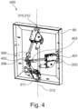
- Fig. 4 illustrates a schematic example of a second subsystem 400 of the motion system 100 (Parallel robot) according to an embodiment of the present invention.
- the second subsystem 400 comprises the first subsystem 300 (see. Fig. 3 ) connected to the ground plate 60 by a third revolute joint 310, 311 with its revolute axes 312, 313 aligned.
- the revolute axis 312, 313 are vertical axis.
- the additional third linear actuation system 202 is connected to the ground plate 60 by a third universal joint 401 and to a fifth kinematic link 402 by a (universal) fourth joint 403.
- the second kinematic link 402 is connected to the first subsystem 300 by the second revolute joint 308.
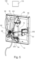
- Fig. 5 illustrates a schematic example of the motion system 100 according to an embodiment of the present invention.
- the difference of the embodiment of the motion system 100 shown in Fig. 1 is that the revolute joints 84, 85,86 are driven by an actuator of a second type 56.
- the actuator of the second type 56 is configured as a Bowden-based actuator.
- the motion system 100 may comprise a plurality of second-type actuators 56.
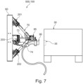
- Fig. 7 illustrates a schematic example of a robot system 500 with the motion system 100 according to an embodiment of the present invention.
- the robot or robot system 500 with the motion system 100 comprises a tool element 90 that is embodied as a plug.
- the plug is to inserted in the inlet 35 of a vehicle 30.
- the motion system 100 is used for positioning the plug in an aligned position in respect to the inlet element 35 in order to connect the plug 90 with the inlet element 35 for charging the vehicle 30.
- the motion system 100 is responsible for the movement or in other words, the correct positioning of the plug 90 in front of the inlet element 35 of the vehicle 30.
Landscapes
- Engineering & Computer Science (AREA)
- Mechanical Engineering (AREA)
- Robotics (AREA)
- Power Engineering (AREA)
- Transportation (AREA)
- Manipulator (AREA)
Abstract
- a linear actuation system (201, 202, 203) comprising a plurality of actuators of a first-type (50, 52, 54) and at least a first kinematic link (70, 72, 74) connected by an eighth joint (305, 306, 307) to the plurality of first-type actuators (50, 52, 54);
- a first subsystem (300) comprising at least one linear actuation system (201, 203) connected to at least a fourth kinematic link (301) by at least a first revolute joint (303, 304) and interconnected between them by a second revolute joint (308);
- a second subsystem (400) comprising the first subsystem (300) connected to a ground plate (60), wherein the linear actuation system (202) connected to the ground plate (60) by a third joint (401) and to a fifth kinematic link (402) by a fourth joint (403), and wherein the second kinematic link (402) is connected to the first subsystem (300);
- a wrist element (80) connectable to at least one tool element (90), wherein the wrist element (80) is connected to the second subsystem (400), wherein the wrist element (80) and the second subsystem (400) are configured to generate a coordinated movement in such a way that the at least one tool element (90) is movable relative to the ground plate (60).
Description
- The present invention relates to a motion system for a robot and robot.
- In prior art, a battery of an electrically driven vehicle needs to be charged with energy. Usually, the vehicle is positioned at a charging station and the vehicle is connected with a plug of the charging station to be charged with energy.
- At the moment, the charging process of such a vehicle is at least partly performed manually with the support of a human. However, as more electrically driven vehicles gain abililty to drive at least partly in an autonomous way, the existing charging process for such a vehicle is complex and not efficient. A robot for supporting the charging process by automatically charging the vehicle parked at the charging station would simply this entire process. Existing technical solutions in this field suggest the use of autonoumous charging robots, for example, described in
WO 2021 / 151 542 A1 or inUS 2020 / 1448 38 A1 . - However, such charging robots are bulky and use complex technology, in particular for the charging plug to be connected to the charging inlet of the vehicle to perform an efficient charging process is not time- and cost-efficient. In particular, the existing technology of positioning the charging plug of the charging robot by a robot arm or robot manipulator of the charging robot relative to the charging inlet of the vehicle to be charged is complex thus, the charging process is not efficient.
- There is a need to address these issues.
- Therefore, it would be advantageous to provide an improved concept for a motion system for a robot that is easy to produce and maintain and that is easily adaptable for different applications and which can be operated at low-costs.
- The object of the present invention is solved by the subject matter of the independent claims, wherein further embodiments are incorporated in the dependent claims.
- In a first aspect of the present invention, there is provided a motion system comprising:
- a linear actuation system comprising a plurality of actuators of a first-type and at least a first kinematic link connected by an eighth joint to the plurality of first-type actuators;
- a first subsystem comprising at least one linear actuation system connected to at least a fourth kinematic link by at least a first revolute joint and interconnected between them by a second revolute joint;
- a second subsystem comprising the first subsystem connected to a ground plate, wherein the linear actuation system is connected to the ground plate by a third joint and to a fifth kinematic link by a fourth joint, and wherein the second kinematic link is connected to the first subsystem by the second revolute joint;
- a wrist element connectable to at least one tool element, wherein the wrist element is connected to the second subsystem, wherein the wrist element and the second subsystem are configured to generate a coordinated movement in such a way that the at least one tool element is movable relative to the ground plate.
- One important aspect of the motion system is that it is easy to control and that it is a foldable motion system that can be used for example as a robot. As the motion system is foldable due to its kinematic technology, the motion system can be implementated in a robot or robot system or embodied as a robot that does not need much space and thus, is space-saving. This is important for many applications, e.g. when the motion system is used in small places. Using the motion system in or as a charging robot is just one example of an application. The present invention is not restricted to this application, however.
- In a detailed and further aspect of the present invention, the motion system may comprise:
- a linear actuation system comprising a plurality of actuators of a first-type and at least a first kinematic link connected by a eighth joint to the plurality of first-type actuators;
- a first subsystem comprising at least one linear actuation system connected to at least a fourth kinematic link by at least a first revolute joint and interconnected between them by a second revolute joint;
- a second subsystem comprising the first subsystem connected to a ground plate by a third revolute joint with its revolute axes aligned, wherein the linear actuation system connected to the ground plate by a third joint and to a fifth kinematic link by a fourth joint, and wherein the second kinematic link is connected to the first subsystem by the second revolute joint;
- a wrist element connected to at least one tool element, wherein the wrist element is connected to the second subsystem by a fifth revolute joint, wherein the wrist element and the second subsystem are configured to generate a coordinated movement in such a way that the at least one tool element is movable relative to the ground plate.
- As the motion system uses actuators that are embodied as flexible belts, no metal chains are used and need to be maintained in the motion system.
- Further, due to its foldable design, the motion system can be easily aligned to changing positions or locations for which the motion is intended to be used. This allows a large flexibility of the motion system for a variety of different applications.
- A further advantage of the motion system is that it can be produced and operated at low costs and it is easily adaptable to different technical fields of applicationbelt winding system can be easily adapted to different fields of applications.
- According to an example, the wrist element comprising a first kinematic link that is connected to a second kinematic link by a sixth revolute joint, a third kinematic link connected to the first kinematic link by a seventh revolute joint, wherein the axes of the revolute joints intersect at a center of the wrist element. In this way, the motion system provides a flexible functionality that is easy to maintain.
- According to an example, the revolute joints are driven by at least one actuator of a second type. In this way, the motion system is flexible and easy to handle.
- According to an example, the at least one actuator of the second type is configured as a Bowden-based actuator. In this way, the motion system is flexible, accurate and can be operated cost-efficient.
- According to an example, the motion system comprising at least one controller unit configured to communicate with the plurality of actuators of the first-type and is configured to independently drive each of the plurality of kinematic link elements to change a length, and/or speed of the leg elements generating a first-type of movement, wherein this first-type of movement comprises at least one of a change of x-y-z position and/or a velocity, a change of orientation of the first subsystem, measured around by the third revolute joint. In this way, the motion system can be controlled in an easy manner and is easily adaptable to different applications.
- According to an example, the at least one controller unit is further configured to communicate with at least one actuator of a second-type to generate a second-type of movement, wherein this second-type of movement comprises at least one of a change of orientation, a position and/or a velocity of the third kinematic link measured with respect to the position of the second joint and orientation of the first subsystem. In this way, the motion system can be brought in any preferable position in an easy manner.
- According to an example, a coordinated drive of the second subsystem and the wrist element is composed of the first generated type of movement and the second generated type of movement is configured to drive the controllable motion system towards a storing configuration, in which the plurality of actuators of the first-type, the wrist element and the tool element are aligned and fitted in a box with a size along the normal direction of the base ground. In this manner, the motion system can be operated in an efficient manner.
- According to an example, a coordinated drive of the second subsystem and the wrist element is composed of the first generated type of movement and the second generated type of movement moves the tool element from the storing configuration to a distance longer than the size along the normal direction of the base ground. In this manner, the motion system is operated in an efficient manner.
- In a second aspect of the invention, a robot system is provided comprising a motion system according to the first aspect.
- In a third aspect of the invention, the motion system is used as part of a robot system for charging a vehicle.
- Exemplary embodiments will be described in the following with reference to the following drawings:
-
Fig. 1 illustrates a schematic example of a motion system according to an embodiment of the present invention; -
Fig. 1-1 illustrates a schematic example of a wrist element for a motion system according to an embodiment of the present invention; -
Fig. 1-2 illustrates a schematic and detailed example of a part of an actuator system of a motion system according to an embodiment of the present invention; -
Fig. 2 illustrates a schematic example of an actuation system of the motion system according to an embodiment of the present invention; -
Fig. 3 illustrates a schematic example of a subsystem of the motion system (Triangle) according to an embodiment of the present invention; -
Fig. 4 illustrates a schematic example of a subsystem of the motion system (Parallel robot) according to an embodiment of the present invention; -
Fig. 5 illustrates a schematic example of the motion system according to an embodiment of the present invention; -
Fig. 6 illustrates a schematic example of the motion system according to an embodiment of the present invention; -
Fig. 7 illustrates a schematic example of a robot system with the motion system according to an embodiment of the present invention; and -
Fig. 8 illustrates a schematic example of the motion system according to an embodiment of the present invention. -
Fig. 1 illustrates a schematic example of amotion system 100 according to an embodiment of the present invention. - The
motion system 100 comprises of different components: alinear actuation system Fig. 2 for details), a first system system 300 (see alsoFig. 3 for further details), a second subsystem 400 (see alsoFig. 4 for further details) and a wrist element 80 (see alsoFig. 1-1 for further details). - The
linear actuation system motion system 100 comprises a plurality of actuators of a first-type kinematic link type actuators - The
first subsystem 300 of themotion system 100 comprises at least onelinear actuation system kinematic link 301 by at least a first revolute joint 303, 304 and interconnected between them by a second revolute joint 308. - The
second subsystem 400 of themotion system 100 comprises thefirst subsystem 300 connected to aground plate 60 by a third revolute joint 310, 311 with itsrevolute axes 312, 313 aligned, wherein thelinear actuation system 202 connected to theground plate 60 by a third joint 401 and to a fifthkinematic link 402 by a fourth joint 403, and wherein the secondkinematic link 402 is connected to thefirst subsystem 300 by the second revolute joint 308. - The
wrist element 80 is connectable or connected to at least onetool element 90, wherein thewrist element 80 is connected to thesecond subsystem 400 by a fifth revolute joint 84, wherein thewrist element 80 and thesecond subsystem 400 are configured to generate a coordinated movement in such a way that the at least onetool element 90 is movable relative to theground plate 60. - In an embodiment of the invention, the
wrist element 80 and thesecond subsystem 400 are configured to generate a coordinated movement in such a way that the at least onetool element 90 is movable within at least three degrees of freedom relative to theground plate 60. - In an embodiment of the invention, there could be also six degrees of freedom.
- Further, the
motion system 100 is controlled by acontroller unit 110, as shown inFig. 1 for example. - The
controller unit 110 is configured to communicate with the plurality ofactuators controller unit 110 is further configured to independently drive each of the plurality ofkinematic link elements leg elements first subsystem 300, measured around by the third revolute joint 310 (see for exampleFig. 3 ). - As shown in
Fig. 5 , thecontroller unit 110 is further configured to communicate with at least one actuator of a second-type 56 to generate a second-type of movement. The second-type of movement comprises at least one of a change of orientation, a position and/or a velocity of the thirdkinematic link 83 measured with respect to the position of the second joint 308 (seeFig. 4 ) and orientation of thefirst subsystem 300. - The movement of the
tool element 90 to a defined position by themotion system 100 may be execute in the following manner: - A coordinated drive of the
second subsystem 400 and thewrist element 80 is composed of the first generated type of movement and the second generated type of movement is configured to drive thecontrollable motion system 100 towards a storing configuration, in which the plurality of actuators of the first-type wrist element 80 and the tool element 90 (seeFig. 1 ) are aligned and fitted in a box with a size along the normal direction of thebase ground 60. An example for such abox 120 is depicted inFig. 8 . The dimension or thickness of such abox 120 is about or less than 150 mm and is just an example. Other dimensions of such abox 120 are possible and are dependent on the application. - Further, a coordinated drive of the
second subsystem 400 and thewrist element 80 is composed of the first generated type of movement and the second generated type of movement moves thetool element 90 from the storing configuration to a distance longer than the size along the normal direction of thebase ground 60. - In this respect, it should be further mentioned that a use of a sensing device, e.g. camera, lidar, laser, and a perception methodology to correct and drive the coordinated motion of the linear actuation systems of first and second type to drive the tool (e.g. plug) towards a desired target. In this way, loose tolerances are allowed that can significantly decrease the cost of the motion system.
-
Fig. 1-1 illustrates a schematic example of awrist element 80 for themotion system 100 according to an embodiment of the present invention. - The
wrist element 80 ofFig. 1-1 shows a section A ofFig. 1 in detail. Thewrist element 80. Thewrist element 80 comprises a firstkinematic link 81 that is connected to a secondkinematic link 82 by a sixth revolute joint 85. A thirdkinematic link 83 is connected to the firstkinematic link 82 by a seventh revolute joint 86, wherein theaxes revolute joints center 317 of thewrist element 80, as shown in detail inFig. 1-1 Theaxe 314 is an x-axis, theaxis 316 is the z-axis of thewrist element 80. -
Fig. 1-2 illustrates a schematic and detailed example of a part of anactuator system 201 of amotion system 100 according to an embodiment of the present invention. - The
Fig. 1-2 shows alinear actuator system 201 comprising a corresponding first actuator of a first-type 50. Thelinear actuator system 201 is mounted or installed by means of first revolute joint 303 at theground plate 60. Correspondingly, the two otherlinear actuator systems linear actuator system 202 with a second actuator offirst type 52 and thelinear actuator system 203 with a third actuator offirst type 54 are mounted in an equivalent manner at theground plate 60, as shown inFig. 1 for example. -
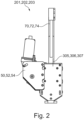
Fig. 2 illustrates a schematic example of alinear actuatation system motion system 100 according to an embodiment of the present invention. TheFig. 2 shows a part of thelinear actuation system Fig. 1 . Each of thelinear actuation systems kinematic link linear actuation systems first type -
Fig. 3 illustrates a schematic example of afirst subsystem 300 of the motion system (Triangle) according to an embodiment of the present invention. Thesubsystem 300 comprising at least onelinear actuation system kinematic link 301 by firstrevolute joints linear actuation systems subsystem 300 forms a triangle. -
Fig. 4 illustrates a schematic example of asecond subsystem 400 of the motion system 100 (Parallel robot) according to an embodiment of the present invention. - The
second subsystem 400 comprises the first subsystem 300 (see.Fig. 3 ) connected to theground plate 60 by a third revolute joint 310, 311 with itsrevolute axes 312, 313 aligned. Therevolute axis 312, 313 are vertical axis. The additional thirdlinear actuation system 202 is connected to theground plate 60 by a thirduniversal joint 401 and to a fifthkinematic link 402 by a (universal)fourth joint 403. The secondkinematic link 402 is connected to thefirst subsystem 300 by the second revolute joint 308. -
Fig. 5 illustrates a schematic example of themotion system 100 according to an embodiment of the present invention. The difference of the embodiment of themotion system 100 shown inFig. 1 is that therevolute joints second type 56. The actuator of thesecond type 56 is configured as a Bowden-based actuator. Themotion system 100 may comprise a plurality of second-type actuators 56. -
Fig. 6 illustrates a schematic example of themotion system 100 according to an embodiment of the present invention. Compared to themotion system 100 as shown inFig. 1 , themotion system 100 inFig. 6 is in a folded position. TheFig. 1 ,3 ,4 ,5 and7 each show amotion system 100 in an unfolded position. -
Fig. 7 illustrates a schematic example of a robot system 500 with themotion system 100 according to an embodiment of the present invention. The robot or robot system 500 with themotion system 100 comprises atool element 90 that is embodied as a plug. The plug is to inserted in theinlet 35 of avehicle 30. In this example scenario of an application of the robot system 500 with themotion system 100, themotion system 100 is used for positioning the plug in an aligned position in respect to theinlet element 35 in order to connect theplug 90 with theinlet element 35 for charging thevehicle 30. - The
motion system 100 is responsible for the movement or in other words, the correct positioning of theplug 90 in front of theinlet element 35 of thevehicle 30. -
- 30
- Vehicle
- 35
- Inlet element
- 50, 52, 54
- First-type actuator
- 56
- Second-type actuator / Bowden - Actuator
- 60
- Ground plate
- 70, 72, 74
- First kinematic link
- 75, 76, 77
- Belt element
- 80
- Wrist element
- 81
- First kinematic link
- 82
- Second kinematic link
- 83
- Third kinematic link
- 84
- Fifth revolute joint
- 85
- Sixth revolute joint
- 86
- Seventh revolute joint
- 90
- Tool element
- 100
- Motion system
- 110
- Controller unit
- 120
- Box
- 201, 202, 203
- Linear actuation system
- 300
- First subsystem
- 301
- Fourth kinematic link
- 303, 304
- First revolute joint
- 308
- Second revolute joint
- 305, 306, 307
- EighthJoint
- 310, 311
- Third revolute joint
- 312, 313
- Revolute axe
- 314, 315, 316
- Revolute axe
- 317
- Center of the wrist element
- 400
- Second subsystem
- 401
- Third joint
- 402
- Fifth kinematic link
- 403
- Fourth joint
- 500
- Robot system
Claims (9)
- Motion system (100) comprising:- a linear actuation system (201, 202, 203) comprising a plurality of actuators of a first-type (50, 52, 54) and at least a first kinematic link (70, 72, 74) connected by a eighth joint (305, 306, 307) to the plurality of first-type actuators (50, 52, 54);- a first subsystem (300) comprising at least one linear actuation system (201, 203) connected to at least a fourth kinematic link (301) by at least a first revolute joint (303, 304) and interconnected between them by a second revolute joint (308);- a second subsystem (400) comprising the first subsystem (300) connected to a ground plate (60), wherein the linear actuation system (202) connected to the ground plate (60) by a third joint (401) and to a fifth kinematic link (402) by a fourth joint (403), and wherein the second kinematic link (402) is connected to the first subsystem (300);- a wrist element (80) connectable to at least one tool element (90), wherein the wrist element (80) is connected to the second subsystem (400), wherein the wrist element (80) and the second subsystem (400) are configured to generate a coordinated movement in such a way that the at least one tool element (90) is movable relative to the ground plate (60).
- Motion system (100) according to claim 1, wherein the wrist element (80) comprising a first kinematic link (81) that is connected to a second kinematic link (82) by a sixth revolute joint (85), a third kinematic link (83) connected to the first kinematic link (82) by a seventh revolute joint (86), wherein the axes (314, 315, 316) of the revolute joints (84, 85, 86) intersect at a center (317) of the wrist element (80).
- Motion system (100) according to claim 2 wherein the revolute joints (84, 85,86) are driven by at least one actuator of a second type (56).
- Motion system (100) according to claim 3, wherein the at least one actuator of the second type (56) is configured as a Bowden-based actuator.
- Motion system (100) according to any of the previous claims, comprising at least one controller unit (110) configured to communicate with the plurality of actuators (50, 52, 54) of the first-type and is configured to independently drive each of the plurality of kinematic link elements (70, 72, 74) to change a length, and/or speed of the leg elements (70, 72, 74) generating a first-type of movement, wherein this first-type of movement comprises at least one of a change of x-y-z position and/or a velocity, a change of orientation of the first subsystem (300), measured around by the third revolute joint (310).
- Motion system (100) according to claim 4, wherein the at least one controller unit (110) is further configured to communicate with at least one actuator of a second-type (56) to generate a second-type of movement, wherein this second-type of movement comprises at least one of a change of orientation, a position and/or a velocity of the third kinematic link (83) measured with respect to the position of the second joint (308) and orientation of the first subsystem (300).
- Motion system (100) according to any one of the previous claims 4 to 5, wherein a coordinated drive of the second subsystem (400) and the wrist element (80) composed of the first generated type of movement and the second generated type of movement is configured to drive the controllable motion system (100) towards a storing configuration, in which the plurality of actuators of the first-type (50, 52, 54), the wrist element (80) and the tool element (90) are aligned and fitted in a box with a size along the normal direction of the base ground (60).
- Motion system (100) according to claim 6, wherein a coordinated drive of the second subsystem (400) and the wrist element (80) composed of the first generated type of movement and the second generated type of movement moves the tool element (90) from the storing configuration to a distance longer than the size along the normal direction of the base ground (60).
- Robot system (500) comprising a motion system (100) according to the one of the previous claims 1 to 8.
Priority Applications (2)
| Application Number | Priority Date | Filing Date | Title |
|---|---|---|---|
| EP23188507.0A EP4497625A1 (en) | 2023-07-28 | 2023-07-28 | Motion system for a robot and robot |
| US18/785,361 US20250033229A1 (en) | 2023-07-28 | 2024-07-26 | Motion System for a Robot and Robot |
Applications Claiming Priority (1)
| Application Number | Priority Date | Filing Date | Title |
|---|---|---|---|
| EP23188507.0A EP4497625A1 (en) | 2023-07-28 | 2023-07-28 | Motion system for a robot and robot |
Publications (1)
| Publication Number | Publication Date |
|---|---|
| EP4497625A1 true EP4497625A1 (en) | 2025-01-29 |
Family
ID=87520158
Family Applications (1)
| Application Number | Title | Priority Date | Filing Date |
|---|---|---|---|
| EP23188507.0A Pending EP4497625A1 (en) | 2023-07-28 | 2023-07-28 | Motion system for a robot and robot |
Country Status (2)
| Country | Link |
|---|---|
| US (1) | US20250033229A1 (en) |
| EP (1) | EP4497625A1 (en) |
Citations (11)
| Publication number | Priority date | Publication date | Assignee | Title |
|---|---|---|---|---|
| US2601927A (en) * | 1950-08-07 | 1952-07-01 | Wilbur G Frenzel | Hydraulic crane structure |
| US4652718A (en) * | 1985-05-29 | 1987-03-24 | Honda Giken Kogyo Kabushiki Kaisha | Workpiece feeding apparatus in seam welding machine |
| US7331750B2 (en) * | 2005-03-21 | 2008-02-19 | Michael Merz | Parallel robot |
| DE102011101206A1 (en) * | 2011-05-11 | 2012-11-15 | Fraunhofer-Gesellschaft zur Förderung der angewandten Forschung e.V. | Drive system for driving e.g. delta robot in food industry, has Bowden cables arranged between driving apparatus and joint, where force is exerted on joint through cables for movement of joint with degree of freedom of driving apparatus |
| US20190160653A1 (en) * | 2016-07-26 | 2019-05-30 | Arizona Board Of Regents On Behalf Of Arizona State University | Mechanism for alleviating the effects of joint misalignment between users and wearable robots |
| US20200144838A1 (en) | 2011-04-22 | 2020-05-07 | Emerging Automotive, Llc | Robots for charging electric vehicles (evs) |
| CN112171643A (en) * | 2020-09-30 | 2021-01-05 | 北华航天工业学院 | Six-degree-of-freedom foldable parallel motion platform with closed-loop dual-drive subchains |
| US11077547B2 (en) * | 2014-05-08 | 2021-08-03 | Universite Laval | Parallel mechanism with kinematically redundant actuation |
| WO2021151542A1 (en) | 2020-01-31 | 2021-08-05 | Volkswagen Aktiengesellschaft | Charging robot for inductively charging vehicles |
| CN114274120A (en) * | 2021-12-22 | 2022-04-05 | 燕山大学 | Branch contains redundant drive six degrees of freedom of closed loop and transfers appearance platform |
| US20230108220A1 (en) * | 2020-02-20 | 2023-04-06 | Rocsys B.V | Method for Controlling a Charging Infrastructure |
Family Cites Families (1)
| Publication number | Priority date | Publication date | Assignee | Title |
|---|---|---|---|---|
| US9815377B2 (en) * | 2015-07-06 | 2017-11-14 | Hon Hai Precision Industry Co., Ltd. | Battery charging apparatus and method for charging electric vehicle |
-
2023
- 2023-07-28 EP EP23188507.0A patent/EP4497625A1/en active Pending
-
2024
- 2024-07-26 US US18/785,361 patent/US20250033229A1/en active Pending
Patent Citations (11)
| Publication number | Priority date | Publication date | Assignee | Title |
|---|---|---|---|---|
| US2601927A (en) * | 1950-08-07 | 1952-07-01 | Wilbur G Frenzel | Hydraulic crane structure |
| US4652718A (en) * | 1985-05-29 | 1987-03-24 | Honda Giken Kogyo Kabushiki Kaisha | Workpiece feeding apparatus in seam welding machine |
| US7331750B2 (en) * | 2005-03-21 | 2008-02-19 | Michael Merz | Parallel robot |
| US20200144838A1 (en) | 2011-04-22 | 2020-05-07 | Emerging Automotive, Llc | Robots for charging electric vehicles (evs) |
| DE102011101206A1 (en) * | 2011-05-11 | 2012-11-15 | Fraunhofer-Gesellschaft zur Förderung der angewandten Forschung e.V. | Drive system for driving e.g. delta robot in food industry, has Bowden cables arranged between driving apparatus and joint, where force is exerted on joint through cables for movement of joint with degree of freedom of driving apparatus |
| US11077547B2 (en) * | 2014-05-08 | 2021-08-03 | Universite Laval | Parallel mechanism with kinematically redundant actuation |
| US20190160653A1 (en) * | 2016-07-26 | 2019-05-30 | Arizona Board Of Regents On Behalf Of Arizona State University | Mechanism for alleviating the effects of joint misalignment between users and wearable robots |
| WO2021151542A1 (en) | 2020-01-31 | 2021-08-05 | Volkswagen Aktiengesellschaft | Charging robot for inductively charging vehicles |
| US20230108220A1 (en) * | 2020-02-20 | 2023-04-06 | Rocsys B.V | Method for Controlling a Charging Infrastructure |
| CN112171643A (en) * | 2020-09-30 | 2021-01-05 | 北华航天工业学院 | Six-degree-of-freedom foldable parallel motion platform with closed-loop dual-drive subchains |
| CN114274120A (en) * | 2021-12-22 | 2022-04-05 | 燕山大学 | Branch contains redundant drive six degrees of freedom of closed loop and transfers appearance platform |
Also Published As
| Publication number | Publication date |
|---|---|
| US20250033229A1 (en) | 2025-01-30 |
Similar Documents
| Publication | Publication Date | Title |
|---|---|---|
| Debus et al. | Overview and performance of the front-end robotics enabling near-term demonstration (FREND) robotic arm | |
| RU2706448C2 (en) | Automated dynamic production systems and corresponding methods | |
| EP2789432B1 (en) | Parallel link robot | |
| US8414246B2 (en) | Modular hybrid snake arm | |
| US20110132131A1 (en) | Robot with calibration position | |
| KR20160101809A (en) | Multi-link Type Working Apparatus Moved by Thrust Generating Device | |
| JP2020528010A (en) | Methods for motion sensor modules and field gap inspection robots | |
| CN113021017B (en) | Shape-following self-adaptive 3D detection and processing system | |
| US20100043577A1 (en) | Robotic manipulator | |
| JP2022541998A (en) | Coaxial robotic arm and independent panning of sensory housing | |
| EP3808510B1 (en) | Tele-commanded robot | |
| Lee et al. | A highly redundant robot system for inspection | |
| CN106541391A (en) | All-around mobile parallel robot and cooperating method | |
| WO2014120301A2 (en) | Modular and reconfigurable manufacturing systems | |
| CN110545952A (en) | Robot system and work line provided with same | |
| CN115256344B (en) | Omnidirectional carrying gesture-adjusting platform for large-weight equipment under condition of large depth in cabin | |
| EP4497625A1 (en) | Motion system for a robot and robot | |
| McCormick et al. | REMORA CubeSat for large debris rendezvous, attachment, tracking, and collision avoidance | |
| Nishida et al. | A new end-effector for on-orbit assembly of a large reflector | |
| CN206287136U (en) | All-around mobile parallel robot | |
| JP2585382B2 (en) | Modularization of space-based spacecraft robot | |
| Liu et al. | Spiral zipper manipulator for aerial grasping and manipulation | |
| Huber et al. | Design of a saccading and accommodating robot vision system | |
| CN121364375B (en) | Insulator detection system and insulator detection method | |
| Patil et al. | A review paper on introduction of parallel manipulator and control system |
Legal Events
| Date | Code | Title | Description |
|---|---|---|---|
| PUAI | Public reference made under article 153(3) epc to a published international application that has entered the european phase |
Free format text: ORIGINAL CODE: 0009012 |
|
| STAA | Information on the status of an ep patent application or granted ep patent |
Free format text: STATUS: THE APPLICATION HAS BEEN PUBLISHED |
|
| AK | Designated contracting states |
Kind code of ref document: A1 Designated state(s): AL AT BE BG CH CY CZ DE DK EE ES FI FR GB GR HR HU IE IS IT LI LT LU LV MC ME MK MT NL NO PL PT RO RS SE SI SK SM TR |
|
| STAA | Information on the status of an ep patent application or granted ep patent |
Free format text: STATUS: REQUEST FOR EXAMINATION WAS MADE |
|
| STAA | Information on the status of an ep patent application or granted ep patent |
Free format text: STATUS: EXAMINATION IS IN PROGRESS |
|
| 17P | Request for examination filed |
Effective date: 20250728 |
|
| 17Q | First examination report despatched |
Effective date: 20250818 |
|
| GRAP | Despatch of communication of intention to grant a patent |
Free format text: ORIGINAL CODE: EPIDOSNIGR1 |
|
| STAA | Information on the status of an ep patent application or granted ep patent |
Free format text: STATUS: GRANT OF PATENT IS INTENDED |
|
| INTG | Intention to grant announced |
Effective date: 20260122 |