EP4497618A1 - Hybrid power transmission system - Google Patents
Hybrid power transmission system Download PDFInfo
- Publication number
- EP4497618A1 EP4497618A1 EP24175410.0A EP24175410A EP4497618A1 EP 4497618 A1 EP4497618 A1 EP 4497618A1 EP 24175410 A EP24175410 A EP 24175410A EP 4497618 A1 EP4497618 A1 EP 4497618A1
- Authority
- EP
- European Patent Office
- Prior art keywords
- electric machine
- wheel
- transmission wheel
- transmission
- power
- Prior art date
- Legal status (The legal status is an assumption and is not a legal conclusion. Google has not performed a legal analysis and makes no representation as to the accuracy of the status listed.)
- Pending
Links
Images





Classifications
-
- B—PERFORMING OPERATIONS; TRANSPORTING
- B60—VEHICLES IN GENERAL
- B60K—ARRANGEMENT OR MOUNTING OF PROPULSION UNITS OR OF TRANSMISSIONS IN VEHICLES; ARRANGEMENT OR MOUNTING OF PLURAL DIVERSE PRIME-MOVERS IN VEHICLES; AUXILIARY DRIVES FOR VEHICLES; INSTRUMENTATION OR DASHBOARDS FOR VEHICLES; ARRANGEMENTS IN CONNECTION WITH COOLING, AIR INTAKE, GAS EXHAUST OR FUEL SUPPLY OF PROPULSION UNITS IN VEHICLES
- B60K6/00—Arrangement or mounting of plural diverse prime-movers for mutual or common propulsion, e.g. hybrid propulsion systems comprising electric motors and internal combustion engines
- B60K6/20—Arrangement or mounting of plural diverse prime-movers for mutual or common propulsion, e.g. hybrid propulsion systems comprising electric motors and internal combustion engines the prime-movers consisting of electric motors and internal combustion engines, e.g. HEVs
- B60K6/42—Arrangement or mounting of plural diverse prime-movers for mutual or common propulsion, e.g. hybrid propulsion systems comprising electric motors and internal combustion engines the prime-movers consisting of electric motors and internal combustion engines, e.g. HEVs characterised by the architecture of the hybrid electric vehicle
- B60K6/44—Series-parallel type
-
- B—PERFORMING OPERATIONS; TRANSPORTING
- B60—VEHICLES IN GENERAL
- B60K—ARRANGEMENT OR MOUNTING OF PROPULSION UNITS OR OF TRANSMISSIONS IN VEHICLES; ARRANGEMENT OR MOUNTING OF PLURAL DIVERSE PRIME-MOVERS IN VEHICLES; AUXILIARY DRIVES FOR VEHICLES; INSTRUMENTATION OR DASHBOARDS FOR VEHICLES; ARRANGEMENTS IN CONNECTION WITH COOLING, AIR INTAKE, GAS EXHAUST OR FUEL SUPPLY OF PROPULSION UNITS IN VEHICLES
- B60K6/00—Arrangement or mounting of plural diverse prime-movers for mutual or common propulsion, e.g. hybrid propulsion systems comprising electric motors and internal combustion engines
- B60K6/20—Arrangement or mounting of plural diverse prime-movers for mutual or common propulsion, e.g. hybrid propulsion systems comprising electric motors and internal combustion engines the prime-movers consisting of electric motors and internal combustion engines, e.g. HEVs
- B60K6/42—Arrangement or mounting of plural diverse prime-movers for mutual or common propulsion, e.g. hybrid propulsion systems comprising electric motors and internal combustion engines the prime-movers consisting of electric motors and internal combustion engines, e.g. HEVs characterised by the architecture of the hybrid electric vehicle
- B60K6/44—Series-parallel type
- B60K6/442—Series-parallel switching type
-
- B—PERFORMING OPERATIONS; TRANSPORTING
- B60—VEHICLES IN GENERAL
- B60K—ARRANGEMENT OR MOUNTING OF PROPULSION UNITS OR OF TRANSMISSIONS IN VEHICLES; ARRANGEMENT OR MOUNTING OF PLURAL DIVERSE PRIME-MOVERS IN VEHICLES; AUXILIARY DRIVES FOR VEHICLES; INSTRUMENTATION OR DASHBOARDS FOR VEHICLES; ARRANGEMENTS IN CONNECTION WITH COOLING, AIR INTAKE, GAS EXHAUST OR FUEL SUPPLY OF PROPULSION UNITS IN VEHICLES
- B60K6/00—Arrangement or mounting of plural diverse prime-movers for mutual or common propulsion, e.g. hybrid propulsion systems comprising electric motors and internal combustion engines
- B60K6/20—Arrangement or mounting of plural diverse prime-movers for mutual or common propulsion, e.g. hybrid propulsion systems comprising electric motors and internal combustion engines the prime-movers consisting of electric motors and internal combustion engines, e.g. HEVs
- B60K6/22—Arrangement or mounting of plural diverse prime-movers for mutual or common propulsion, e.g. hybrid propulsion systems comprising electric motors and internal combustion engines the prime-movers consisting of electric motors and internal combustion engines, e.g. HEVs characterised by apparatus, components or means specially adapted for HEVs
- B60K6/36—Arrangement or mounting of plural diverse prime-movers for mutual or common propulsion, e.g. hybrid propulsion systems comprising electric motors and internal combustion engines the prime-movers consisting of electric motors and internal combustion engines, e.g. HEVs characterised by apparatus, components or means specially adapted for HEVs characterised by the transmission gearings
- B60K6/365—Arrangement or mounting of plural diverse prime-movers for mutual or common propulsion, e.g. hybrid propulsion systems comprising electric motors and internal combustion engines the prime-movers consisting of electric motors and internal combustion engines, e.g. HEVs characterised by apparatus, components or means specially adapted for HEVs characterised by the transmission gearings with the gears having orbital motion
-
- B—PERFORMING OPERATIONS; TRANSPORTING
- B60—VEHICLES IN GENERAL
- B60K—ARRANGEMENT OR MOUNTING OF PROPULSION UNITS OR OF TRANSMISSIONS IN VEHICLES; ARRANGEMENT OR MOUNTING OF PLURAL DIVERSE PRIME-MOVERS IN VEHICLES; AUXILIARY DRIVES FOR VEHICLES; INSTRUMENTATION OR DASHBOARDS FOR VEHICLES; ARRANGEMENTS IN CONNECTION WITH COOLING, AIR INTAKE, GAS EXHAUST OR FUEL SUPPLY OF PROPULSION UNITS IN VEHICLES
- B60K6/00—Arrangement or mounting of plural diverse prime-movers for mutual or common propulsion, e.g. hybrid propulsion systems comprising electric motors and internal combustion engines
- B60K6/20—Arrangement or mounting of plural diverse prime-movers for mutual or common propulsion, e.g. hybrid propulsion systems comprising electric motors and internal combustion engines the prime-movers consisting of electric motors and internal combustion engines, e.g. HEVs
- B60K6/22—Arrangement or mounting of plural diverse prime-movers for mutual or common propulsion, e.g. hybrid propulsion systems comprising electric motors and internal combustion engines the prime-movers consisting of electric motors and internal combustion engines, e.g. HEVs characterised by apparatus, components or means specially adapted for HEVs
- B60K6/38—Arrangement or mounting of plural diverse prime-movers for mutual or common propulsion, e.g. hybrid propulsion systems comprising electric motors and internal combustion engines the prime-movers consisting of electric motors and internal combustion engines, e.g. HEVs characterised by apparatus, components or means specially adapted for HEVs characterised by the driveline clutches
-
- B—PERFORMING OPERATIONS; TRANSPORTING
- B60—VEHICLES IN GENERAL
- B60K—ARRANGEMENT OR MOUNTING OF PROPULSION UNITS OR OF TRANSMISSIONS IN VEHICLES; ARRANGEMENT OR MOUNTING OF PLURAL DIVERSE PRIME-MOVERS IN VEHICLES; AUXILIARY DRIVES FOR VEHICLES; INSTRUMENTATION OR DASHBOARDS FOR VEHICLES; ARRANGEMENTS IN CONNECTION WITH COOLING, AIR INTAKE, GAS EXHAUST OR FUEL SUPPLY OF PROPULSION UNITS IN VEHICLES
- B60K6/00—Arrangement or mounting of plural diverse prime-movers for mutual or common propulsion, e.g. hybrid propulsion systems comprising electric motors and internal combustion engines
- B60K6/20—Arrangement or mounting of plural diverse prime-movers for mutual or common propulsion, e.g. hybrid propulsion systems comprising electric motors and internal combustion engines the prime-movers consisting of electric motors and internal combustion engines, e.g. HEVs
- B60K6/22—Arrangement or mounting of plural diverse prime-movers for mutual or common propulsion, e.g. hybrid propulsion systems comprising electric motors and internal combustion engines the prime-movers consisting of electric motors and internal combustion engines, e.g. HEVs characterised by apparatus, components or means specially adapted for HEVs
- B60K6/38—Arrangement or mounting of plural diverse prime-movers for mutual or common propulsion, e.g. hybrid propulsion systems comprising electric motors and internal combustion engines the prime-movers consisting of electric motors and internal combustion engines, e.g. HEVs characterised by apparatus, components or means specially adapted for HEVs characterised by the driveline clutches
- B60K6/387—Actuated clutches, i.e. clutches engaged or disengaged by electric, hydraulic or mechanical actuating means
-
- B—PERFORMING OPERATIONS; TRANSPORTING
- B60—VEHICLES IN GENERAL
- B60K—ARRANGEMENT OR MOUNTING OF PROPULSION UNITS OR OF TRANSMISSIONS IN VEHICLES; ARRANGEMENT OR MOUNTING OF PLURAL DIVERSE PRIME-MOVERS IN VEHICLES; AUXILIARY DRIVES FOR VEHICLES; INSTRUMENTATION OR DASHBOARDS FOR VEHICLES; ARRANGEMENTS IN CONNECTION WITH COOLING, AIR INTAKE, GAS EXHAUST OR FUEL SUPPLY OF PROPULSION UNITS IN VEHICLES
- B60K6/00—Arrangement or mounting of plural diverse prime-movers for mutual or common propulsion, e.g. hybrid propulsion systems comprising electric motors and internal combustion engines
- B60K6/20—Arrangement or mounting of plural diverse prime-movers for mutual or common propulsion, e.g. hybrid propulsion systems comprising electric motors and internal combustion engines the prime-movers consisting of electric motors and internal combustion engines, e.g. HEVs
- B60K6/22—Arrangement or mounting of plural diverse prime-movers for mutual or common propulsion, e.g. hybrid propulsion systems comprising electric motors and internal combustion engines the prime-movers consisting of electric motors and internal combustion engines, e.g. HEVs characterised by apparatus, components or means specially adapted for HEVs
- B60K6/40—Arrangement or mounting of plural diverse prime-movers for mutual or common propulsion, e.g. hybrid propulsion systems comprising electric motors and internal combustion engines the prime-movers consisting of electric motors and internal combustion engines, e.g. HEVs characterised by apparatus, components or means specially adapted for HEVs characterised by the assembly or relative disposition of components
-
- B—PERFORMING OPERATIONS; TRANSPORTING
- B60—VEHICLES IN GENERAL
- B60K—ARRANGEMENT OR MOUNTING OF PROPULSION UNITS OR OF TRANSMISSIONS IN VEHICLES; ARRANGEMENT OR MOUNTING OF PLURAL DIVERSE PRIME-MOVERS IN VEHICLES; AUXILIARY DRIVES FOR VEHICLES; INSTRUMENTATION OR DASHBOARDS FOR VEHICLES; ARRANGEMENTS IN CONNECTION WITH COOLING, AIR INTAKE, GAS EXHAUST OR FUEL SUPPLY OF PROPULSION UNITS IN VEHICLES
- B60K6/00—Arrangement or mounting of plural diverse prime-movers for mutual or common propulsion, e.g. hybrid propulsion systems comprising electric motors and internal combustion engines
- B60K6/20—Arrangement or mounting of plural diverse prime-movers for mutual or common propulsion, e.g. hybrid propulsion systems comprising electric motors and internal combustion engines the prime-movers consisting of electric motors and internal combustion engines, e.g. HEVs
- B60K6/42—Arrangement or mounting of plural diverse prime-movers for mutual or common propulsion, e.g. hybrid propulsion systems comprising electric motors and internal combustion engines the prime-movers consisting of electric motors and internal combustion engines, e.g. HEVs characterised by the architecture of the hybrid electric vehicle
- B60K6/44—Series-parallel type
- B60K6/445—Differential gearing distribution type
-
- B—PERFORMING OPERATIONS; TRANSPORTING
- B60—VEHICLES IN GENERAL
- B60K—ARRANGEMENT OR MOUNTING OF PROPULSION UNITS OR OF TRANSMISSIONS IN VEHICLES; ARRANGEMENT OR MOUNTING OF PLURAL DIVERSE PRIME-MOVERS IN VEHICLES; AUXILIARY DRIVES FOR VEHICLES; INSTRUMENTATION OR DASHBOARDS FOR VEHICLES; ARRANGEMENTS IN CONNECTION WITH COOLING, AIR INTAKE, GAS EXHAUST OR FUEL SUPPLY OF PROPULSION UNITS IN VEHICLES
- B60K7/00—Disposition of motor in, or adjacent to, traction wheel
- B60K7/0007—Disposition of motor in, or adjacent to, traction wheel the motor being electric
-
- B—PERFORMING OPERATIONS; TRANSPORTING
- B60—VEHICLES IN GENERAL
- B60W—CONJOINT CONTROL OF VEHICLE SUB-UNITS OF DIFFERENT TYPE OR DIFFERENT FUNCTION; CONTROL SYSTEMS SPECIALLY ADAPTED FOR HYBRID VEHICLES; ROAD VEHICLE DRIVE CONTROL SYSTEMS FOR PURPOSES NOT RELATED TO THE CONTROL OF A PARTICULAR SUB-UNIT
- B60W20/00—Control systems specially adapted for hybrid vehicles
- B60W20/20—Control strategies involving selection of hybrid configuration, e.g. selection between series or parallel configuration
-
- B—PERFORMING OPERATIONS; TRANSPORTING
- B60—VEHICLES IN GENERAL
- B60W—CONJOINT CONTROL OF VEHICLE SUB-UNITS OF DIFFERENT TYPE OR DIFFERENT FUNCTION; CONTROL SYSTEMS SPECIALLY ADAPTED FOR HYBRID VEHICLES; ROAD VEHICLE DRIVE CONTROL SYSTEMS FOR PURPOSES NOT RELATED TO THE CONTROL OF A PARTICULAR SUB-UNIT
- B60W20/00—Control systems specially adapted for hybrid vehicles
- B60W20/40—Controlling the engagement or disengagement of prime movers, e.g. for transition between prime movers
-
- B—PERFORMING OPERATIONS; TRANSPORTING
- B60—VEHICLES IN GENERAL
- B60Y—INDEXING SCHEME RELATING TO ASPECTS CROSS-CUTTING VEHICLE TECHNOLOGY
- B60Y2200/00—Type of vehicle
- B60Y2200/10—Road Vehicles
- B60Y2200/12—Motorcycles, Trikes; Quads; Scooters
-
- B—PERFORMING OPERATIONS; TRANSPORTING
- B60—VEHICLES IN GENERAL
- B60Y—INDEXING SCHEME RELATING TO ASPECTS CROSS-CUTTING VEHICLE TECHNOLOGY
- B60Y2200/00—Type of vehicle
- B60Y2200/90—Vehicles comprising electric prime movers
- B60Y2200/92—Hybrid vehicles
-
- Y—GENERAL TAGGING OF NEW TECHNOLOGICAL DEVELOPMENTS; GENERAL TAGGING OF CROSS-SECTIONAL TECHNOLOGIES SPANNING OVER SEVERAL SECTIONS OF THE IPC; TECHNICAL SUBJECTS COVERED BY FORMER USPC CROSS-REFERENCE ART COLLECTIONS [XRACs] AND DIGESTS
- Y02—TECHNOLOGIES OR APPLICATIONS FOR MITIGATION OR ADAPTATION AGAINST CLIMATE CHANGE
- Y02T—CLIMATE CHANGE MITIGATION TECHNOLOGIES RELATED TO TRANSPORTATION
- Y02T10/00—Road transport of goods or passengers
- Y02T10/60—Other road transportation technologies with climate change mitigation effect
- Y02T10/62—Hybrid vehicles
Definitions
- the disclosure relates to a power transmission system, and in particular to a hybrid power transmission system.
- gasoline-electric hybrid vehicles have higher endurance than the electric vehicles and better environmental performance than fuel vehicles.
- the power system of the existing gasoline-electric hybrid vehicles is complex, involving the connection between transmission structures such as fuel engines, electric motors, and gearboxes, and there is energy loss during the power transmission process among various transmission mechanisms, which result in low efficiency in the energy use of the gasoline-electric hybrid vehicles.
- the disclosure provides a hybrid power transmission system which can switch to a hybrid electric mode, a pure engine mode, or a pure motor mode to improve energy efficiency according to different operating situations.
- a hybrid power transmission system of the disclosure includes an engine, a power split device, a first electric machine, a second electric machine, a power controller, an energy storage module, and a wheel.
- the power split device is connected to the engine.
- the first electric machine is connected to the power split device.
- the second electric machine is connected to the power split device.
- the power controller is coupled to the first electric machine and the second electric machine.
- the energy storage module is coupled to the power controller.
- the wheel is connected to the second electric machine.
- the engine is adapted to drive the second electric machine and the wheel by the power split device.
- the energy storage module is adapted to drive the second electric machine and the wheel by the power controller.
- the engine is adapted to drive the first electric machine and drive the second electric machine and the wheel by the power controller.
- the aforementioned power split device has a ring gear, a deceleration gear, a planetary gear set, and a sun gear.
- the deceleration gear is connected to the engine and engages with an external gear of the ring gear.
- the planetary gear set engages with an internal gear of the ring gear.
- the sun gear is connected to the first electric machine and engages with the planetary gear set.
- a clutch is further included and is disposed between the sun gear and the ring gear.
- a transmission mechanism is further included, and the transmission mechanism is connected to the power split device, the second electric machine, and the wheel.
- the aforementioned transmission mechanism has a first transmission wheel, a second transmission wheel, a third transmission wheel, a fourth transmission wheel, and a first chain.
- the first transmission wheel is fixedly connected to the planetary gear set.
- the second transmission wheel is adjacent to the first transmission wheel.
- the third transmission wheel is coaxially connected to the second transmission wheel.
- the fourth transmission wheel is coaxially connected to the second electric machine and the wheel. The fourth transmission wheel engages with the third transmission wheel.
- the aforementioned transmission mechanism has a first transmission wheel, a second transmission wheel, a third transmission wheel, a fourth transmission wheel, a first chain, and a second chain.
- the first transmission wheel is fixedly connected to the planetary gear set.
- the second transmission wheel is adjacent to the first transmission wheel.
- the third transmission wheel is coaxially connected between the second transmission wheel and the second electric machine.
- the fourth transmission wheel is coaxially connected to the wheel.
- the first chain is sleeved on the first transmission wheel and the second transmission wheel.
- the second chain is sleeved on the third transmission wheel and the fourth transmission wheel.
- the clutch in a pure engine mode, locks the sun gear and the ring gear integrally, so that the planetary gear set and the ring gear form a rigid body.
- the engine is adapted to generate a first mechanical energy and directly drive the power split device by the deceleration gear.
- the clutch separates the sun gear and the ring gear.
- the engine is adapted to generate a first mechanical energy. A part of the first mechanical energy drives the second electric machine by the power split device. Another part of the first mechanical energy drives the first electric machine by the power split device to generate a second electric energy.
- the second electric energy is provided to the second electric machine by the power controller. The second electric machine generates a second mechanical energy to drive the wheel.
- the energy storage module in a pure motor mode, the energy storage module generates a first electric energy.
- the first electric energy is provided to the first electric machine and the second electric machine by the power controller.
- the second electric machine generates a second mechanical energy to drive the wheel to rotate.
- the hybrid power transmission system of the disclosure is adaptable for motorcycles, cars, or similar transportation vehicles, and combines the power sources such as engines, first electric machines, second electric machines, and energy storage modules.
- the hybrid power transmission system of the disclosure may switch to the hybrid electric mode, the pure engine mode, or the pure motor mode according to the driving situation and correspondingly turn on or off the engine, the first electric machine, the second electric machine, and the energy storage module to reduce energy consumption and improve the driving endurance performance of the transportation vehicle.
- the hybrid power transmission system of the disclosure switches between the pure engine mode and the hybrid electric mode, switching the clutch is only needed to achieve the switching purpose.
- the hybrid power transmission system of the disclosure simplifies the switching steps and has a simple structure.
- FIG. 1 is a schematic block diagram of a hybrid power transmission system of the disclosure.
- FIG. 2 is a schematic structural connection diagram of the hybrid power transmission system in FIG. 1 according to an embodiment of the disclosure.
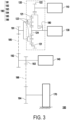
- FIG. 3 is a schematic structural connection diagram of the hybrid power transmission system in FIG. 1 according to another embodiment of the disclosure.
- a hybrid power transmission system 100 of the disclosure is adaptable for motorcycles, cars, or similar transportation vehicles, and includes an engine 110, a power split device 120, a first electric machine 130, a second electric machine 140, a power controller 150, an energy storage module 160, and a wheel 170.
- the engine 110 is disposed in the vehicle and adopts fuel as an energy source.
- the power split device 120 is connected to the engine 110.
- the first electric machine 130 is connected to the power split device 120.
- the second electric machine 140 is connected to the power split device 120.
- the power controller 150 is coupled to the first electric machine 130 and the second electric machine 140.
- the energy storage module 160 is coupled to the power controller 150.
- the wheel 170 is connected to the second electric machine 140.
- the engine 110 is adapted to drive the first electric machine 130 and drive the second electric machine 140 and the wheel 170 by the power controller 150.
- the engine 110 also directly drives the second electric machine 140 by the power split device 120 to switch to a hybrid electric mode.
- the engine 110 is adapted to drive the second electric machine 140 and the wheel 170 by the power split device 120 to switch to a pure engine mode.
- the energy storage module 160 is adapted to drive the second electric machine 140 and the wheel 170 by the power controller to switch to a pure motor mode.
- the power split device 120 has a ring gear 121, a deceleration gear 122, a planetary gear set 123, and a sun gear 124.
- the ring gear 121 has an internal gear and an external gear (not shown in the figures).
- the deceleration gear 122 is connected to a rotating shaft of the engine 110 and engages with the external gear of the ring gear 121. Therefore, the power of the engine 110 may be transmitted to the ring gear 121 by the deceleration gear 122.
- the planetary gear set 123 engages with the internal gear of the ring gear 121, which means that the ring gear 121 may drive the planetary gear set 123 by the internal gear.
- the sun gear 124 is connected to a rotating shaft of the first electric machine 130 and engages with the planetary gear set 123. Therefore, the power generated by the first electric machine 130 may be transmitted to the planetary gear set 123 by the sun gear 124.
- the hybrid power transmission system 100 includes a clutch 180 disposed between the sun gear 124 and the ring gear 121.
- the sun gear 124 and the ring gear 121 are two independent components and are able to rotate freely.
- the clutch 180 is in a junction state, the sun gear 124 and the ring gear 121 are connected integrally and rotate synchronously.
- Multiple power sources of the disclosure change the state of the power split device 120 by a switch of the clutch 180, so the switching steps of the hybrid power transmission system 100 are simplified.
- the hybrid power transmission system 100 includes a transmission mechanism 190.
- the transmission mechanism is connected to the power split device 120, the second electric machine 140, and the wheel 170.
- the power of the engine 110 and the first electric machine 130 is transmitted to the wheel 170 via the power split device 120 and the transmission mechanism 190
- the power of the second electric machine 140 is transmitted to the wheel 170 via the transmission mechanism 190.
- the power sources of the disclosure share the same transmission mechanism 190, so the hybrid power transmission system 100 has a simple structure.
- the transmission mechanism 190 has a first transmission wheel 191, a second transmission wheel 192, a third transmission wheel 193, a fourth transmission wheel 194, and a first chain 195.
- the first transmission wheel 191 is fixedly connected to the planetary gear set 123.
- the second transmission wheel 192 is adjacent to the first transmission wheel 191.
- the third transmission wheel 193 is coaxially connected to the second transmission wheel 192.
- the fourth transmission wheel 194 is coaxially connected to the second electric machine 140 and the wheel 170.
- the fourth transmission wheel 194 also engages with the third transmission wheel 193.
- the second electric machine 140 directly adopts a wheel hub motor and is coaxially installed on the wheel 170.
- a power transmission path of the engine 110 and the first electric machine 130 is from the power split device 120, the first transmission wheel 191, the first chain 195, the second transmission wheel 192, the third transmission wheel 193, the fourth transmission wheel 194, the second electric machine 140, and finally to the wheel 170 in sequence.
- the transmission mechanism 190 has a first transmission wheel 191, a second transmission wheel 192, a third transmission wheel 193, a fourth transmission wheel 194, a first chain. 195, and a second chain 196.
- the first transmission wheel 191 is fixedly connected to the planetary gear set 123.
- the second transmission wheel 192 is adjacent to the first transmission wheel 191.
- the third transmission wheel 193 is coaxially connected between the second transmission wheel 192 and the second electric machine 140.
- the fourth transmission wheel 194 is coaxially connected to the wheel 170.
- the first chain 195 is sleeved on the first transmission wheel 191 and the second transmission wheel 192.
- the second chain 196 is sleeved on the third transmission wheel 193 and the fourth transmission wheel 194.
- the second electric machine 140 is connected in parallel to the power split device 120.
- a power transmission path of the engine 110 and the first electric machine 130 is from the power split device 120, the first transmission wheel 191, the first chain 195, the second transmission wheel 192, the third transmission wheel 193, the second electric machine 140, the second chain 196, the fourth transmission wheel 194, and finally to the wheel 170 in sequence.
- FIG. 4A is a schematic power transmission block diagram of the hybrid power transmission system in FIG. 1 in a hybrid electric mode.
- FIG. 4B is a rotational speed relationship diagram of an engine, a first electric machine, and a second electric machine in FIG. 4A .
- the clutch 180 unlocks the sun gear 124 and the ring gear 121.
- the engine 110 is adapted to generate a first mechanical energy M1 for transmission to the power split device 120, where a part of the first mechanical energy M1 directly drives the wheel 170 by the deceleration gear 122, the ring gear 121, and the transmission mechanism 190 to rotate, and another part of the first mechanical energy M1 drives the first electric machine 130 by the deceleration gear 122, the ring gear 121, and the sun gear 124 to generate a first electric energy E1.
- the first electric energy E1 is provided to the second electric machine 140 by the power controller 150.
- the aforementioned first mechanical energy M1 and the aforementioned first electric energy E1 are combined, which makes the second electric machine 140 generate a second mechanical energy M2 to drive the wheel 170 to rotate.
- r e is a deceleration ratio of the output terminal of the engine 110 to the external gear of the ring gear 121
- r t is a deceleration ratio of the planetary gear set 123 to the wheel 170
- k ' is a ratio of the number of gears of the internal gear of the ring gear 121 to the sun gear 124.
- the torque and rotational speed of the second electric machine 140 depend on an installation position of the second electric machine 140.
- FIG. 7 is a schematic diagram of mode switching rules of the hybrid power transmission system in FIG. 1 .
- the hybrid electric mode is adaptable for slow acceleration and low speed cruise.
- the first mechanical energy M1 generated by the engine 110 simultaneously drives the second electric machine 140 and the first electric machine 130, thereby adjusting the rotational speed and an operating point of the engine 110 to achieve energy saving and variable speed functions.
- the first electric machine 130 switches to a generator in the hybrid electric mode, generates the first electric energy E1, and directly drives the second electric machine 140.
- the first electric machine 130 also serves as a load of the transmission system and continuously changes a ratio of the input speed of the engine 110 to the output rotational speed of the wheel 170.
- FIG. 5A is a schematic power transmission block diagram of the hybrid power transmission system in FIG. 1 in a pure engine mode.
- FIG. 5B is a rotational speed relationship diagram of an engine, a first electric machine, and a second electric machine in FIG. 5A .
- the clutch 180 locks the sun gear 124 and the ring gear 121 integrally, so that the planetary gear set 123 and the ring gear 121 form a rigid body.
- the engine 110 is adapted to generate the first mechanical energy M1 and directly drive the power split device 120 by the deceleration gear 122, and the power split device 120 directly drives the second electric machine 140 and the wheel 170 to rotate by the transmission mechanism 190.
- T s , T r , and T c are the output torques of the sun gear 124, the ring gear 121, and the planetary gear set 123 respectively. Since the planetary gear set 123 and the ring gear 121 form the rigid body, the values of the output torques of the three are equal.
- the pure engine mode is adaptable for high speed cruise.
- the first mechanical energy M1 generated by the engine 110 directly drives the second electric machine 140 and the wheel 170 by the power split device 120 and the transmission mechanism 190. Since the first electric machine 130 and the power split device 120 form a rigid body, all the first mechanical energy M1 generated by the engine 110 is used to drive the second electric machine 140 and the wheel 170 to avoid the energy loss of converting mechanical energy into electric energy.
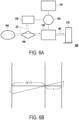
- FIG. 6A is a schematic power transmission block diagram of the hybrid power transmission system in FIG. 1 in a pure motor mode.
- FIG. 6B is a rotational speed relationship diagram of an engine, a first electric machine, and a second electric machine in FIG. 6A .
- the energy storage module 160 when the hybrid power transmission system 100 is in the pure motor mode, the engine 110 is not started, the energy storage module 160 generates a second electric energy E2 and provides the second electric energy E2 to the first electric machine 130 and the second by the power controller 150, and the second electric machine 140 generates a second mechanical energy M2 to drive the wheel 170 to rotate.
- the first electric machine 130 here serves as a load that consumes parts of the second electric energy E2 and continuously changes the total amount of electric energy input by the energy storage module 160 to the second electric machine 140, thereby adjusting the output rotational speed of the wheel 170.
- the pure motor mode is adaptable for a start situation to prevent the engine 110 from consuming fuel in a stationary state.
- the hybrid power transmission system of the disclosure is adaptable for motorcycles, cars, or similar transportation vehicles, and combines the power sources such as engines, first electric machines, second electric machines, and energy storage modules.
- the hybrid power transmission system of the disclosure may switch to the hybrid electric mode, the pure engine mode, or the pure motor mode according to the driving situation and correspondingly turn on or off the engine, the first electric machine, the second electric machine, and the energy storage module to reduce energy consumption and improve the driving endurance performance of the transportation vehicle.
- the hybrid power transmission system of the disclosure switches between the pure engine mode and the hybrid electric mode, the clutch is turned on and off only to achieve the switching purpose.
- the hybrid power transmission system of the disclosure simplifies the switching steps and has a simple structure.
Landscapes
- Engineering & Computer Science (AREA)
- Transportation (AREA)
- Mechanical Engineering (AREA)
- Chemical & Material Sciences (AREA)
- Combustion & Propulsion (AREA)
- Automation & Control Theory (AREA)
- Hybrid Electric Vehicles (AREA)
- Electric Propulsion And Braking For Vehicles (AREA)
- Structure Of Transmissions (AREA)
- Auxiliary Drives, Propulsion Controls, And Safety Devices (AREA)
Abstract
Disclosed is a hybrid power transmission system (100) including an engine (110), a power split device (120), a first electric machine (130), a second electric machine (140), a power controller (150), an energy storage module (160), and a wheel (170). The power split device (120) is connected to the engine (110). The first electric machine (130) is connected to the power split device (120). The second electric machine (140) is connected to the power split device (120). The power controller (150) is coupled to the first electric machine (130) and the second electric machine (140). The energy storage module (160) is coupled to the power controller (150). The wheel (170) is connected to the second electric machine (140).
Description
- The disclosure relates to a power transmission system, and in particular to a hybrid power transmission system.
- Nowadays, with the rise of environmental awareness in the world, more and more countries have begun to formulate relevant laws to regulate the environmental standards of fuel vehicles. As a result, electric vehicles are booming. As a kind of transportation vehicle that is different from fuel vehicles, the electric vehicles have the advantages of not emitting exhaust gas and low noise, and are regarded as an important tool to achieve low-carbon transportation.
- However, the development of existing energy storage technology and charging technology is limited, resulting in a bottleneck in the cruising range of the electric vehicles. Therefore, as a transitional product before the complete development of the electric vehicles, gasoline-electric hybrid vehicles have higher endurance than the electric vehicles and better environmental performance than fuel vehicles. Yet, the power system of the existing gasoline-electric hybrid vehicles is complex, involving the connection between transmission structures such as fuel engines, electric motors, and gearboxes, and there is energy loss during the power transmission process among various transmission mechanisms, which result in low efficiency in the energy use of the gasoline-electric hybrid vehicles.
- The disclosure provides a hybrid power transmission system which can switch to a hybrid electric mode, a pure engine mode, or a pure motor mode to improve energy efficiency according to different operating situations.
- A hybrid power transmission system of the disclosure includes an engine, a power split device, a first electric machine, a second electric machine, a power controller, an energy storage module, and a wheel. The power split device is connected to the engine. The first electric machine is connected to the power split device. The second electric machine is connected to the power split device. The power controller is coupled to the first electric machine and the second electric machine. The energy storage module is coupled to the power controller. The wheel is connected to the second electric machine. The engine is adapted to drive the second electric machine and the wheel by the power split device. The energy storage module is adapted to drive the second electric machine and the wheel by the power controller. The engine is adapted to drive the first electric machine and drive the second electric machine and the wheel by the power controller.
- In an embodiment of the disclosure, the aforementioned power split device has a ring gear, a deceleration gear, a planetary gear set, and a sun gear. The deceleration gear is connected to the engine and engages with an external gear of the ring gear. The planetary gear set engages with an internal gear of the ring gear. The sun gear is connected to the first electric machine and engages with the planetary gear set.
- In an embodiment of the disclosure, a clutch is further included and is disposed between the sun gear and the ring gear.
- In an embodiment of the disclosure, a transmission mechanism is further included, and the transmission mechanism is connected to the power split device, the second electric machine, and the wheel.
- In an embodiment of the disclosure, the aforementioned transmission mechanism has a first transmission wheel, a second transmission wheel, a third transmission wheel, a fourth transmission wheel, and a first chain. The first transmission wheel is fixedly connected to the planetary gear set. The second transmission wheel is adjacent to the first transmission wheel. The third transmission wheel is coaxially connected to the second transmission wheel. The fourth transmission wheel is coaxially connected to the second electric machine and the wheel. The fourth transmission wheel engages with the third transmission wheel.
- In an embodiment of the disclosure, the aforementioned transmission mechanism has a first transmission wheel, a second transmission wheel, a third transmission wheel, a fourth transmission wheel, a first chain, and a second chain. The first transmission wheel is fixedly connected to the planetary gear set. The second transmission wheel is adjacent to the first transmission wheel. The third transmission wheel is coaxially connected between the second transmission wheel and the second electric machine. The fourth transmission wheel is coaxially connected to the wheel. The first chain is sleeved on the first transmission wheel and the second transmission wheel. The second chain is sleeved on the third transmission wheel and the fourth transmission wheel.
- In an embodiment of the disclosure, in a pure engine mode, the clutch locks the sun gear and the ring gear integrally, so that the planetary gear set and the ring gear form a rigid body. The engine is adapted to generate a first mechanical energy and directly drive the power split device by the deceleration gear.
- In an embodiment of the disclosure, in a hybrid electric mode, the clutch separates the sun gear and the ring gear. The engine is adapted to generate a first mechanical energy. A part of the first mechanical energy drives the second electric machine by the power split device. Another part of the first mechanical energy drives the first electric machine by the power split device to generate a second electric energy. The second electric energy is provided to the second electric machine by the power controller. The second electric machine generates a second mechanical energy to drive the wheel.
- In an embodiment of the disclosure, in a pure motor mode, the energy storage module generates a first electric energy. The first electric energy is provided to the first electric machine and the second electric machine by the power controller. The second electric machine generates a second mechanical energy to drive the wheel to rotate.
- Based on the above, the hybrid power transmission system of the disclosure is adaptable for motorcycles, cars, or similar transportation vehicles, and combines the power sources such as engines, first electric machines, second electric machines, and energy storage modules. The hybrid power transmission system of the disclosure may switch to the hybrid electric mode, the pure engine mode, or the pure motor mode according to the driving situation and correspondingly turn on or off the engine, the first electric machine, the second electric machine, and the energy storage module to reduce energy consumption and improve the driving endurance performance of the transportation vehicle.
- Further, when the hybrid power transmission system of the disclosure switches between the pure engine mode and the hybrid electric mode, switching the clutch is only needed to achieve the switching purpose. Compared with the existing compound power system, the hybrid power transmission system of the disclosure simplifies the switching steps and has a simple structure.
-
-
FIG. 1 is a schematic block diagram of a hybrid power transmission system of the disclosure. -
FIG. 2 is a schematic structural connection diagram of the hybrid power transmission system inFIG. 1 according to an embodiment of the disclosure. -
FIG. 3 is a schematic structural connection diagram of the hybrid power transmission system inFIG. 1 according to another embodiment of the disclosure. -
FIG. 4A is a schematic power transmission block diagram of the hybrid power transmission system inFIG. 1 in a hybrid electric mode. -
FIG. 4B is a rotational speed relationship diagram of an engine, a first electric machine, and a second electric machine inFIG. 4A . -
FIG. 5A is a schematic power transmission block diagram of the hybrid power transmission system inFIG. 1 in a pure engine mode. -
FIG. 5B is a rotational speed relationship diagram of an engine, a first electric machine, and a second electric machine inFIG. 5A . -
FIG. 6A is a schematic power transmission block diagram of the hybrid power transmission system inFIG. 1 in a pure motor mode. -
FIG. 6B is a rotational speed relationship diagram of an engine, a first electric machine, and a second electric machine inFIG. 6A . -
FIG. 7 is a schematic diagram of mode switching rules of the hybrid power transmission system inFIG. 1 . -
FIG. 1 is a schematic block diagram of a hybrid power transmission system of the disclosure.FIG. 2 is a schematic structural connection diagram of the hybrid power transmission system inFIG. 1 according to an embodiment of the disclosure.FIG. 3 is a schematic structural connection diagram of the hybrid power transmission system inFIG. 1 according to another embodiment of the disclosure. - Referring to
FIG. 1 to FIG. 3 , a hybridpower transmission system 100 of the disclosure is adaptable for motorcycles, cars, or similar transportation vehicles, and includes anengine 110, apower split device 120, a firstelectric machine 130, a secondelectric machine 140, apower controller 150, anenergy storage module 160, and awheel 170. - The
engine 110 is disposed in the vehicle and adopts fuel as an energy source. The power splitdevice 120 is connected to theengine 110. The firstelectric machine 130 is connected to thepower split device 120. The secondelectric machine 140 is connected to thepower split device 120. Thepower controller 150 is coupled to the firstelectric machine 130 and the secondelectric machine 140. Theenergy storage module 160 is coupled to thepower controller 150. Thewheel 170 is connected to the secondelectric machine 140. - Referring to
FIG. 1 , theengine 110 is adapted to drive the firstelectric machine 130 and drive the secondelectric machine 140 and thewheel 170 by thepower controller 150. Theengine 110 also directly drives the secondelectric machine 140 by thepower split device 120 to switch to a hybrid electric mode. Theengine 110 is adapted to drive the secondelectric machine 140 and thewheel 170 by thepower split device 120 to switch to a pure engine mode. Theenergy storage module 160 is adapted to drive the secondelectric machine 140 and thewheel 170 by the power controller to switch to a pure motor mode. - Referring to
FIG. 2 andFIG. 3 , thepower split device 120 has aring gear 121, adeceleration gear 122, a planetary gear set 123, and asun gear 124. - The
ring gear 121 has an internal gear and an external gear (not shown in the figures). Thedeceleration gear 122 is connected to a rotating shaft of theengine 110 and engages with the external gear of thering gear 121. Therefore, the power of theengine 110 may be transmitted to thering gear 121 by thedeceleration gear 122. The planetary gear set 123 engages with the internal gear of thering gear 121, which means that thering gear 121 may drive the planetary gear set 123 by the internal gear. Thesun gear 124 is connected to a rotating shaft of the firstelectric machine 130 and engages with the planetary gear set 123. Therefore, the power generated by the firstelectric machine 130 may be transmitted to the planetary gear set 123 by thesun gear 124. - The hybrid
power transmission system 100 includes a clutch 180 disposed between thesun gear 124 and thering gear 121. When the clutch 180 is in a separated state, thesun gear 124 and thering gear 121 are two independent components and are able to rotate freely. When the clutch 180 is in a junction state, thesun gear 124 and thering gear 121 are connected integrally and rotate synchronously. Multiple power sources of the disclosure change the state of thepower split device 120 by a switch of the clutch 180, so the switching steps of the hybridpower transmission system 100 are simplified. - Referring to
FIG. 2 andFIG. 3 , the hybridpower transmission system 100 includes atransmission mechanism 190. The transmission mechanism is connected to thepower split device 120, the secondelectric machine 140, and thewheel 170. In short, the power of theengine 110 and the firstelectric machine 130 is transmitted to thewheel 170 via thepower split device 120 and thetransmission mechanism 190, and the power of the secondelectric machine 140 is transmitted to thewheel 170 via thetransmission mechanism 190. The power sources of the disclosure share thesame transmission mechanism 190, so the hybridpower transmission system 100 has a simple structure. - Referring to
FIG. 2 , thetransmission mechanism 190 has afirst transmission wheel 191, asecond transmission wheel 192, athird transmission wheel 193, afourth transmission wheel 194, and afirst chain 195. Thefirst transmission wheel 191 is fixedly connected to the planetary gear set 123. Thesecond transmission wheel 192 is adjacent to thefirst transmission wheel 191. Thethird transmission wheel 193 is coaxially connected to thesecond transmission wheel 192. Thefourth transmission wheel 194 is coaxially connected to the secondelectric machine 140 and thewheel 170. Thefourth transmission wheel 194 also engages with thethird transmission wheel 193. The secondelectric machine 140 directly adopts a wheel hub motor and is coaxially installed on thewheel 170. - In short, a power transmission path of the
engine 110 and the firstelectric machine 130 is from thepower split device 120, thefirst transmission wheel 191, thefirst chain 195, thesecond transmission wheel 192, thethird transmission wheel 193, thefourth transmission wheel 194, the secondelectric machine 140, and finally to thewheel 170 in sequence. - Referring to
FIG. 3 , there is difference between this embodiment and the embodiment ofFIG. 2 . The difference lies in that thetransmission mechanism 190 has afirst transmission wheel 191, asecond transmission wheel 192, athird transmission wheel 193, afourth transmission wheel 194, a first chain. 195, and asecond chain 196. Thefirst transmission wheel 191 is fixedly connected to the planetary gear set 123. Thesecond transmission wheel 192 is adjacent to thefirst transmission wheel 191. Thethird transmission wheel 193 is coaxially connected between thesecond transmission wheel 192 and the secondelectric machine 140. Thefourth transmission wheel 194 is coaxially connected to thewheel 170. Thefirst chain 195 is sleeved on thefirst transmission wheel 191 and thesecond transmission wheel 192. Thesecond chain 196 is sleeved on thethird transmission wheel 193 and thefourth transmission wheel 194. The secondelectric machine 140 is connected in parallel to thepower split device 120. - In short, a power transmission path of the
engine 110 and the firstelectric machine 130 is from thepower split device 120, thefirst transmission wheel 191, thefirst chain 195, thesecond transmission wheel 192, thethird transmission wheel 193, the secondelectric machine 140, thesecond chain 196, thefourth transmission wheel 194, and finally to thewheel 170 in sequence. -
FIG. 4A is a schematic power transmission block diagram of the hybrid power transmission system inFIG. 1 in a hybrid electric mode.FIG. 4B is a rotational speed relationship diagram of an engine, a first electric machine, and a second electric machine inFIG. 4A . - Referring to
FIG. 2 ,FIG. 4A, and FIG. 4B , when the hybridpower transmission system 100 is in the hybrid electric mode, the clutch 180 unlocks thesun gear 124 and thering gear 121. Theengine 110 is adapted to generate a first mechanical energy M1 for transmission to thepower split device 120, where a part of the first mechanical energy M1 directly drives thewheel 170 by thedeceleration gear 122, thering gear 121, and thetransmission mechanism 190 to rotate, and another part of the first mechanical energy M1 drives the firstelectric machine 130 by thedeceleration gear 122, thering gear 121, and thesun gear 124 to generate a first electric energy E1. The first electric energy E1 is provided to the secondelectric machine 140 by thepower controller 150. The aforementioned first mechanical energy M1 and the aforementioned first electric energy E1 are combined, which makes the secondelectric machine 140 generate a second mechanical energy M2 to drive thewheel 170 to rotate. - Referring to
FIG. 4B , a torque relationship of thehybrid powertrain 100 is the following equation:
sun gear 124, thering gear 121, and the planetary gear set 123 respectively. The parameter k' is defined as the following equation: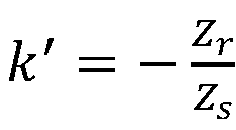
ring gear 121 and thesun gear 124 respectively. - The rotational speed relationship of the
hybrid powertrain 100 is the following equation: ωs + k'ωr - (k' + 1)ωc = 0, where ωs, ωr , and ωc are the rotational speeds of thesun gear 124, thering gear 121, and the planetary gear set 123 respectively. Since k' < 0 and -(k' + 1) > 0, Ts and Tc have the same sign, so thering gear 121 is connected to theengine 110 and serves as a power input terminal, while thesun gear 124 and the planetary gear set 123 serve as power load terminals or power output terminals. - According to a connection way of the hybrid power transmission system in
FIG. 3 , the relationship between the rotational speed and the torque may be written as the following equation:

- Among them, re is a deceleration ratio of the output terminal of the
engine 110 to the external gear of thering gear 121, rt is a deceleration ratio of the planetary gear set 123 to thewheel 170, and k' is a ratio of the number of gears of the internal gear of thering gear 121 to thesun gear 124. The torque and rotational speed of the secondelectric machine 140 depend on an installation position of the secondelectric machine 140. -
FIG. 7 is a schematic diagram of mode switching rules of the hybrid power transmission system inFIG. 1 . - Referring to
FIG. 7 , the hybrid electric mode is adaptable for slow acceleration and low speed cruise. The first mechanical energy M1 generated by theengine 110 simultaneously drives the secondelectric machine 140 and the firstelectric machine 130, thereby adjusting the rotational speed and an operating point of theengine 110 to achieve energy saving and variable speed functions. In addition, the firstelectric machine 130 switches to a generator in the hybrid electric mode, generates the first electric energy E1, and directly drives the secondelectric machine 140. At the same time, the firstelectric machine 130 also serves as a load of the transmission system and continuously changes a ratio of the input speed of theengine 110 to the output rotational speed of thewheel 170. -
FIG. 5A is a schematic power transmission block diagram of the hybrid power transmission system inFIG. 1 in a pure engine mode.FIG. 5B is a rotational speed relationship diagram of an engine, a first electric machine, and a second electric machine inFIG. 5A . - Referring to
FIG. 3 ,FIG. 5A, and FIG. 5B , when the hybridpower transmission system 100 is in the pure engine mode, the clutch 180 locks thesun gear 124 and thering gear 121 integrally, so that the planetary gear set 123 and thering gear 121 form a rigid body. Theengine 110 is adapted to generate the first mechanical energy M1 and directly drive thepower split device 120 by thedeceleration gear 122, and thepower split device 120 directly drives the secondelectric machine 140 and thewheel 170 to rotate by thetransmission mechanism 190. - Referring to
FIG. 5B , Ts, Tr, and Tc are the output torques of thesun gear 124, thering gear 121, and the planetary gear set 123 respectively. Since the planetary gear set 123 and thering gear 121 form the rigid body, the values of the output torques of the three are equal. - Referring to
FIG. 7 , the pure engine mode is adaptable for high speed cruise. The first mechanical energy M1 generated by theengine 110 directly drives the secondelectric machine 140 and thewheel 170 by thepower split device 120 and thetransmission mechanism 190. Since the firstelectric machine 130 and thepower split device 120 form a rigid body, all the first mechanical energy M1 generated by theengine 110 is used to drive the secondelectric machine 140 and thewheel 170 to avoid the energy loss of converting mechanical energy into electric energy. -
FIG. 6A is a schematic power transmission block diagram of the hybrid power transmission system inFIG. 1 in a pure motor mode.FIG. 6B is a rotational speed relationship diagram of an engine, a first electric machine, and a second electric machine inFIG. 6A . - Referring to
FIG. 3 ,FIG. 6A, and FIG. 6B , when the hybridpower transmission system 100 is in the pure motor mode, theengine 110 is not started, theenergy storage module 160 generates a second electric energy E2 and provides the second electric energy E2 to the firstelectric machine 130 and the second by thepower controller 150, and the secondelectric machine 140 generates a second mechanical energy M2 to drive thewheel 170 to rotate. Specifically, the firstelectric machine 130 here serves as a load that consumes parts of the second electric energy E2 and continuously changes the total amount of electric energy input by theenergy storage module 160 to the secondelectric machine 140, thereby adjusting the output rotational speed of thewheel 170. - Referring to
FIG. 6B , the rotational speed relationship of the hybridpower transmission system 100 is the following equation: ωs + k'ωr - (k' + 1)ωc = 0, where ωs , ωr , and ωc are the rotational speeds of thesun gear 124, thering gear 121, and the planetary gear set 123 respectively. Since k' > 0 and -(k' + 1) < 0, Ts and Tc have different signs, that is, a direction of torque action is opposite, so the planetary gear set 123 is connected to the secondelectric machine 140 and serves as the power output terminal, while thesun gear 124 serves as the power load terminal. - Referring to
FIG. 7 , the pure motor mode is adaptable for a start situation to prevent theengine 110 from consuming fuel in a stationary state. - Based on the above, the hybrid power transmission system of the disclosure is adaptable for motorcycles, cars, or similar transportation vehicles, and combines the power sources such as engines, first electric machines, second electric machines, and energy storage modules. The hybrid power transmission system of the disclosure may switch to the hybrid electric mode, the pure engine mode, or the pure motor mode according to the driving situation and correspondingly turn on or off the engine, the first electric machine, the second electric machine, and the energy storage module to reduce energy consumption and improve the driving endurance performance of the transportation vehicle.
- Further, when the hybrid power transmission system of the disclosure switches between the pure engine mode and the hybrid electric mode, the clutch is turned on and off only to achieve the switching purpose. Compared with the existing compound power system, the hybrid power transmission system of the disclosure simplifies the switching steps and has a simple structure.
Claims (9)
- A hybrid power transmission system (100), comprising:an engine (110);a power split device (120), connected to the engine (110);a first electric machine (130), connected to the power split device (120);a second electric machine (140), connected to the power split device (120);a power controller (150), coupled to the first electric machine (130) and the second electric machine (140);an energy storage module (160), coupled to the power controller (150); anda wheel (170), connected to the second electric machine (140),wherein, the engine (110) is adapted to drive the second electric machine (140) and the wheel (170) by the power split device (120), the energy storage module (160) is adapted to drive the second electric machine (140) and the wheel (170) by the power controller (150), and the engine (110) is adapted to drive the first electric machine (130) and drive the second electric machine (140) and the wheel (170) by the power controller (150).
- The hybrid power transmission system (100) according to claim 1, wherein the power split device (120) has a ring gear (121), a deceleration gear (122), a planetary gear set (123), and a sun gear (124), the deceleration gear (122) is connected to the engine (110) and engages with an external gear of the ring gear (121), the planetary gear set (123) engages with an internal gear of the ring gear (121), and the sun gear (124) is connected to the first electric machine (130) and engages with the planetary gear set (123).
- The hybrid power transmission system (100) according to claim 2, further comprising a clutch (180) disposed between the sun gear (124) and the ring gear (121).
- The hybrid power transmission system (100) according to claim 2, further comprising a transmission mechanism (190), wherein the transmission mechanism (190) is connected to the power split device (120), the second electric machine (140), and the wheel (170).
- The hybrid power transmission system (100) according to claim 4, wherein the transmission mechanism (190) has a first transmission wheel (191), a second transmission wheel (192), a third transmission wheel (193), a fourth transmission wheel (194), and a first chain (195), the first transmission wheel (191) is fixedly connected to the planetary gear set (123), the second transmission wheel (192) is adjacent to the first transmission wheel (191), the third transmission wheel (193) is coaxially connected to the second transmission wheel (192), the fourth transmission wheel (194) is coaxially connected to the second electric machine (140) and the wheel (170), and the fourth transmission wheel (194) engages with the third transmission wheel (193).
- The hybrid power transmission system (100) according to claim 4, wherein the transmission mechanism (190) has a first transmission wheel (191), a second transmission wheel (192), a third transmission wheel (193), a fourth transmission wheel (194), a first chain (195), and a second chain (196), the first transmission wheel (191) is fixedly connected to the planetary gear set (123), the second transmission wheel (192) is adjacent to the first transmission wheel (191), the third transmission wheel (193) is coaxially connected between the second transmission wheel (192) and the second electric machine (140), the fourth transmission wheel (194) is coaxially connected to the wheel (170), the first chain (195) is sleeved on the first transmission wheel (191) and the second transmission wheel (192), and the second chain (196) is sleeved on the third transmission wheel (193) and the fourth transmission wheel (194).
- The hybrid power transmission system (100) according to claim 3, wherein in a pure engine mode, the clutch (180) locks the sun gear (124) and the ring gear (121) integrally, so that the planetary gear set (123) and the ring gear (121) form a rigid body, and the engine (110) is adapted to generate a first mechanical energy (M1) and directly drive the power split device (120) by the deceleration gear (122).
- The hybrid power transmission system (100) according to claim 3, wherein in a hybrid electric mode, the clutch (180) separates the sun gear (124) and the ring gear (121), the engine (110) is adapted to generate a first mechanical energy (M1), a part of the first mechanical energy (M1) drives the second electric machine (140) by the power split device (120), another part of the first mechanical energy (M1) drives the first electric machine (130) by the power split device (120) to generate a second electric energy, the second electric energy is provided to the second electric machine (140) by the power controller (150), and the second electric machine (140) generates a second mechanical energy (M2) to drive the wheel (170).
- The hybrid power transmission system (100) according to claim 1, wherein in a pure motor mode, the energy storage module (160) generates a first electric energy, the first electric energy is provided to the first electric machine (130) and the second electric machine (140) by the power controller (150), and the second electric machine (140) generates a second mechanical energy (M2) to drive the wheel (170) to rotate.
Applications Claiming Priority (1)
| Application Number | Priority Date | Filing Date | Title |
|---|---|---|---|
| TW112128163A TWI862043B (en) | 2023-07-27 | 2023-07-27 | Hybrid power transmission system |
Publications (1)
| Publication Number | Publication Date |
|---|---|
| EP4497618A1 true EP4497618A1 (en) | 2025-01-29 |
Family
ID=91076902
Family Applications (1)
| Application Number | Title | Priority Date | Filing Date |
|---|---|---|---|
| EP24175410.0A Pending EP4497618A1 (en) | 2023-07-27 | 2024-05-13 | Hybrid power transmission system |
Country Status (5)
| Country | Link |
|---|---|
| US (1) | US12365233B2 (en) |
| EP (1) | EP4497618A1 (en) |
| JP (1) | JP7744054B2 (en) |
| KR (1) | KR20250017648A (en) |
| TW (1) | TWI862043B (en) |
Families Citing this family (1)
| Publication number | Priority date | Publication date | Assignee | Title |
|---|---|---|---|---|
| TWI878152B (en) * | 2024-06-20 | 2025-03-21 | 亞福儲能股份有限公司 | Hybrid power system |
Citations (3)
| Publication number | Priority date | Publication date | Assignee | Title |
|---|---|---|---|---|
| EP0967102A2 (en) * | 1998-06-24 | 1999-12-29 | General Motors Corporation | Hybrid vehicle compound transmission with two electric motors |
| US20160101681A1 (en) * | 2013-05-13 | 2016-04-14 | Toyota Jidosha Kabushiki Kaisha | Hybrid-vehicle driving device |
| US10780769B1 (en) * | 2019-04-25 | 2020-09-22 | Hyundai Motor Company | Power transmission apparatus of hybrid electric vehicle |
Family Cites Families (12)
| Publication number | Priority date | Publication date | Assignee | Title |
|---|---|---|---|---|
| JP3292120B2 (en) | 1997-12-10 | 2002-06-17 | 日産自動車株式会社 | Vehicle driving assist device |
| CN101992679B (en) * | 2009-08-24 | 2013-09-25 | 上海华普国润汽车有限公司 | Double planetary row four-axis hybrid power transmission device |
| JP5530813B2 (en) * | 2010-06-04 | 2014-06-25 | トヨタ自動車株式会社 | Hybrid vehicle and control method thereof |
| US9457667B2 (en) * | 2011-12-14 | 2016-10-04 | Toyota Jidosha Kabushiki Kaisha | Vehicle control device |
| CN106915244A (en) * | 2015-12-25 | 2017-07-04 | 比亚迪股份有限公司 | Power-driven system and the vehicle with the power-driven system |
| JP6743617B2 (en) | 2016-03-23 | 2020-08-19 | トヨタ自動車株式会社 | Power transmission device |
| JP6604279B2 (en) * | 2016-07-08 | 2019-11-13 | トヨタ自動車株式会社 | Vehicle drive device |
| CN111231647A (en) * | 2018-11-28 | 2020-06-05 | 郑州宇通客车股份有限公司 | Planet series-parallel system and vehicle |
| KR102895290B1 (en) | 2020-12-10 | 2025-12-03 | 현대자동차주식회사 | Driving control device for electric four-wheel driving vehicle |
| US20240017727A1 (en) * | 2022-01-27 | 2024-01-18 | Deere & Company | System and method for traction control in a work vehicle with an electric infinitely variable transmission using wheel speed |
| CN114734805B (en) * | 2022-03-29 | 2024-04-09 | 南通大任永磁电机制造有限公司 | Electric vehicle, hybrid power device and transmission method thereof |
| TWM637878U (en) | 2022-06-30 | 2023-02-21 | 三陽工業股份有限公司 | Fuel-electricity hybrid system of motorcycle |
-
2023
- 2023-07-27 TW TW112128163A patent/TWI862043B/en active
-
2024
- 2024-04-16 US US18/637,443 patent/US12365233B2/en active Active
- 2024-05-13 EP EP24175410.0A patent/EP4497618A1/en active Pending
- 2024-05-31 KR KR1020240071621A patent/KR20250017648A/en active Pending
- 2024-06-07 JP JP2024092706A patent/JP7744054B2/en active Active
Patent Citations (3)
| Publication number | Priority date | Publication date | Assignee | Title |
|---|---|---|---|---|
| EP0967102A2 (en) * | 1998-06-24 | 1999-12-29 | General Motors Corporation | Hybrid vehicle compound transmission with two electric motors |
| US20160101681A1 (en) * | 2013-05-13 | 2016-04-14 | Toyota Jidosha Kabushiki Kaisha | Hybrid-vehicle driving device |
| US10780769B1 (en) * | 2019-04-25 | 2020-09-22 | Hyundai Motor Company | Power transmission apparatus of hybrid electric vehicle |
Also Published As
| Publication number | Publication date |
|---|---|
| JP2025018939A (en) | 2025-02-06 |
| TWI862043B (en) | 2024-11-11 |
| US20250033458A1 (en) | 2025-01-30 |
| KR20250017648A (en) | 2025-02-04 |
| JP7744054B2 (en) | 2025-09-25 |
| TW202504777A (en) | 2025-02-01 |
| US12365233B2 (en) | 2025-07-22 |
Similar Documents
| Publication | Publication Date | Title |
|---|---|---|
| US8287412B2 (en) | Hybrid power train of vehicle | |
| KR101500356B1 (en) | Power transmission system of hybrid electric vehicle | |
| US11679661B2 (en) | Power split hybrid power system and hybrid vehicle | |
| EP3750734B1 (en) | Hybrid transmission and hybrid electric vehicle | |
| KR101459472B1 (en) | Power transmission system of hybrid electric vehicle | |
| KR101405232B1 (en) | Power transmission system of hybrid electric vehicle | |
| KR101459466B1 (en) | Power transmission system of hybrid electric vehicle | |
| KR101500355B1 (en) | Power transmission system of hybrid electric vehicle | |
| KR101646114B1 (en) | Power transmission system of hybrid electric vehicle | |
| KR101500357B1 (en) | Power transmission system of hybrid electric vehicle | |
| CN105109326B (en) | A hybrid power transmission drive device | |
| KR101427952B1 (en) | Power transmission system of hybrid electric vehicle | |
| CN214138222U (en) | Dual-motor hybrid power driving system | |
| KR101550629B1 (en) | Power transmission system of hybrid electric vehicle | |
| KR20150003615A (en) | Power transmission system of hybrid electric vehicle | |
| CN105128647A (en) | Multimode hybrid power transmission driving device | |
| CN109130831B (en) | A vehicle multi-mode hybrid power coupling device | |
| CN109017268B (en) | Hybrid power system and control method | |
| KR101534748B1 (en) | Power transmission system of hybrid electric vehicle | |
| EP4497618A1 (en) | Hybrid power transmission system | |
| Yang et al. | Integrated electro-mechanical transmission systems in hybrid electric vehicles | |
| CN102303515B (en) | Power system of hybrid electric vehicle | |
| CN109649151B (en) | Transmission system of plug-in double-row hybrid electric vehicle | |
| CN102211518A (en) | Travel increasing type power system for hybrid automobile | |
| CN215705646U (en) | Special speed changer for hybrid power |
Legal Events
| Date | Code | Title | Description |
|---|---|---|---|
| PUAI | Public reference made under article 153(3) epc to a published international application that has entered the european phase |
Free format text: ORIGINAL CODE: 0009012 |
|
| STAA | Information on the status of an ep patent application or granted ep patent |
Free format text: STATUS: REQUEST FOR EXAMINATION WAS MADE |
|
| 17P | Request for examination filed |
Effective date: 20240513 |
|
| AK | Designated contracting states |
Kind code of ref document: A1 Designated state(s): AL AT BE BG CH CY CZ DE DK EE ES FI FR GB GR HR HU IE IS IT LI LT LU LV MC ME MK MT NL NO PL PT RO RS SE SI SK SM TR |