EP4497583A1 - Repairing a hat stringer - Google Patents
Repairing a hat stringer Download PDFInfo
- Publication number
- EP4497583A1 EP4497583A1 EP24178401.6A EP24178401A EP4497583A1 EP 4497583 A1 EP4497583 A1 EP 4497583A1 EP 24178401 A EP24178401 A EP 24178401A EP 4497583 A1 EP4497583 A1 EP 4497583A1
- Authority
- EP
- European Patent Office
- Prior art keywords
- stringer
- repair
- segment
- hat
- mounting location
- Prior art date
- Legal status (The legal status is an assumption and is not a legal conclusion. Google has not performed a legal analysis and makes no representation as to the accuracy of the status listed.)
- Pending
Links
Images






Classifications
-
- B—PERFORMING OPERATIONS; TRANSPORTING
- B29—WORKING OF PLASTICS; WORKING OF SUBSTANCES IN A PLASTIC STATE IN GENERAL
- B29C—SHAPING OR JOINING OF PLASTICS; SHAPING OF MATERIAL IN A PLASTIC STATE, NOT OTHERWISE PROVIDED FOR; AFTER-TREATMENT OF THE SHAPED PRODUCTS, e.g. REPAIRING
- B29C73/00—Repairing of articles made from plastics or substances in a plastic state, e.g. of articles shaped or produced by using techniques covered by this subclass or subclass B29D
- B29C73/04—Repairing of articles made from plastics or substances in a plastic state, e.g. of articles shaped or produced by using techniques covered by this subclass or subclass B29D using preformed elements
-
- B—PERFORMING OPERATIONS; TRANSPORTING
- B64—AIRCRAFT; AVIATION; COSMONAUTICS
- B64F—GROUND OR AIRCRAFT-CARRIER-DECK INSTALLATIONS SPECIALLY ADAPTED FOR USE IN CONNECTION WITH AIRCRAFT; DESIGNING, MANUFACTURING, ASSEMBLING, CLEANING, MAINTAINING OR REPAIRING AIRCRAFT, NOT OTHERWISE PROVIDED FOR; HANDLING, TRANSPORTING, TESTING OR INSPECTING AIRCRAFT COMPONENTS, NOT OTHERWISE PROVIDED FOR
- B64F5/00—Designing, manufacturing, assembling, cleaning, maintaining or repairing aircraft, not otherwise provided for; Handling, transporting, testing or inspecting aircraft components, not otherwise provided for
- B64F5/40—Maintaining or repairing aircraft
-
- B—PERFORMING OPERATIONS; TRANSPORTING
- B64—AIRCRAFT; AVIATION; COSMONAUTICS
- B64C—AEROPLANES; HELICOPTERS
- B64C3/00—Wings
- B64C3/18—Spars; Ribs; Stringers
- B64C3/182—Stringers, longerons
-
- B—PERFORMING OPERATIONS; TRANSPORTING
- B23—MACHINE TOOLS; METAL-WORKING NOT OTHERWISE PROVIDED FOR
- B23P—METAL-WORKING NOT OTHERWISE PROVIDED FOR; COMBINED OPERATIONS; UNIVERSAL MACHINE TOOLS
- B23P6/00—Restoring or reconditioning objects
-
- B—PERFORMING OPERATIONS; TRANSPORTING
- B23—MACHINE TOOLS; METAL-WORKING NOT OTHERWISE PROVIDED FOR
- B23P—METAL-WORKING NOT OTHERWISE PROVIDED FOR; COMBINED OPERATIONS; UNIVERSAL MACHINE TOOLS
- B23P2700/00—Indexing scheme relating to the articles being treated, e.g. manufactured, repaired, assembled, connected or other operations covered in the subgroups
- B23P2700/01—Aircraft parts
Definitions
- the present disclosure relates to repair of aircraft structural components, and more particularly, to repair of hat stringers.
- Aircraft structures must be capable of handling loads in a variety of different directions.
- an aircraft wing must be capable of handling aerodynamic loads that are imposed on the wing during flight.
- Such aerodynamic loads include bending loads that are reacted by the wing skin and the internal wing structure. Bending loads are typically reacted by stiffeners or stringers in the internal wing structure.
- Stringers are coupled to the wing skin and generally extend in a spanwise direction along the wing interior. Stringers may be provided in a variety of different cross-sectional shapes and sizes, including with a hat-shaped cross section.
- a hat-shaped stringer, or simply hat stringer typically includes a pair of webs that extend from a base portion of the stringer and are connected by a cap to enclose the hat-shaped cross section.
- hat stringers can be become damaged or otherwise in need of reinforcement, e.g., due to an impact event.
- Conventional techniques for repairing damaged hat stringers has presented certain challenges. Accordingly, one or more improved hat stringer repair techniques and/or repair stringers are needed.
- the method includes arranging a repair stringer in a mounting location that is one of a plurality of possible mounting locations along a cross section of a hat stringer, and in each of the plurality of possible mounting locations, at least a portion of an internal profile of the repair stringer matches at least a portion of a profile of an internal cavity defined by the hat stringer, and wherein a cross-sectional area of the repair stringer as viewed along a first direction is less than a total cross-sectional area of the hat stringer as viewed along the first direction.
- the method also includes coupling the repair stringer with a stringer of the hat stringer in the mounting location.
- the repair stringer has a web segment that extends parallel with a web portion of the profile of the internal cavity.
- the repair stringer has at least one segment that extends parallel with a cap portion of the internal cavity or a flange segment of the stringer.
- the hat stringer defines a central plane demarcating a first side and a second side of the hat stringer, and wherein the plurality of possible mounting locations include a first possible mounting location in which the repair stringer is positioned primarily on the first side of the hat stringer and a second possible mounting location in which the repair stringer is positioned primarily on the second side of the hat stringer.
- the repair stringer has a cap segment, a flange segment, and a web segment extending between and connecting the cap segment and the flange segment, and wherein in arranging the repair stringer in the mounting location, the cap segment, the web segment, and the flange segment of the repair stringer respectively extend parallel with a cap segment, a web segment, and a flange segment of the stringer.
- the repair stringer is a first repair stringer
- the method further includes arranging a second repair stringer in a mounting location along the cross section of the hat stringer, the second repair stringer is shaped to have an internal profile that matches at least a portion of the profile of the internal cavity, and wherein a cap segment of the second repair stringer and a cap segment of the first repair stringer physically overlap one another and each extend parallel with a cap portion of the profile of the internal cavity.
- the first repair stringer has a web segment that physically overlaps a first web segment of the stringer and the second repair stringer has a web segment that physically overlaps a second web segment of the stringer.
- the second repair stringer has a flange segment that extends parallel with, but is spaced from, a second flange segment of the stringer, and wherein the method further includes placing one or more shims between the second flange segment and the flange segment of the second repair stringer.
- the second repair stringer has a same cross-sectional shape as the first repair stringer as viewed along the first direction.
- the method further includes arranging a second repair stringer in a mounting location along the cross section of the hat stringer, the second repair stringer is shaped to have an internal profile that matches at least a portion of the profile of the internal cavity.
- the method may also include arranging a third repair stringer in a mounting location along the cross section of the hat stringer, the third repair stringer has a first web segment, a cap segment, and a second web segment. The first web segment may be coupled with the repair stringer, the cap segment is coupled with the stringer, and the second web segment is coupled with the second repair stringer.
- the hat stringer defines a central plane demarcating a first side and a second side of the hat stringer and the plurality of possible mounting locations include at least four possible mounting locations, and wherein the at least four possible mounting locations include at least two possible mounting locations in which the repair stringer is capable of being positioned primarily on the first side of the hat stringer and at least two possible mounting locations in which the repair stringer is capable of being positioned primarily on the second side of the hat stringer.
- the at least two possible mounting locations in which the repair stringer is capable of being positioned primarily on the first side of the hat stringer include a first mounting location and a second mounting location, and in the first mounting location, one segment of the repair stringer extends parallel with a first flange segment of the stringer and one segment of the repair stringer extends parallel with a first web segment of the stringer, and in the second mounting location, one segment of the repair stringer extends parallel with a cap segment of the stringer and one segment of the repair stringer extends parallel with the first web segment of the stringer.
- the at least two possible mounting locations in which the repair stringer is positioned primarily on the second side of the hat stringer include a first mounting location and a second mounting location, and in the first mounting location, one segment of the repair stringer extends parallel with a cap segment of the stringer and one segment of the repair stringer extends parallel with a second web segment of the stringer, and in the second mounting location, one segment of the repair stringer extends parallel with a second flange segment of the stringer and one segment of the repair stringer extends parallel with the second web segment of the stringer.
- the stringer includes a first flange segment, a first web segment, a cap segment, a second web segment, and a second flange segment
- the plurality of possible mounting locations along the cross section of the hat stringer include a first mounting location, a second mounting location, a third mounting location, and a fourth mounting location, and: in the first mounting location, one segment of the repair stringer extends parallel with the first flange segment of the stringer and one segment of the repair stringer extends parallel with a first web segment of the stringer, in the second mounting location, one segment of the repair stringer extends parallel with the cap segment of the stringer and one segment of the repair stringer extends parallel with the first web segment of the stringer, in the third mounting location, one segment of the repair stringer extends parallel with the cap segment of the stringer and one segment of the repair stringer extends parallel with the second web segment of the stringer, and in the fourth mounting location, one segment of the repair stringer extends parallel with the second flange segment of the string
- the repair stringer is a first repair stringer and the mounting location is the first mounting location
- the method further includes arranging a second repair stringer in the second mounting location; arranging a third repair stringer in the third mounting location; arranging a fourth repair stringer in the fourth mounting location; and coupling the second repair stringer, the third repair stringer, and the fourth repair stringer to the stringer in the second mounting location, the third mounting location, and the fourth mounting location, respectively, the first repair stringer being coupled with the stringer in the first mounting location.
- first and second repair stringers physically overlap one another
- second and third repair stringers physically overlap one another
- third and fourth repair stringers physically overlap one another
- the first, second, third, and fourth repair stringers all have a same cross-sectional shape as viewed along the first direction, and wherein the second repair stringer is oriented so as to be flipped vertically and horizontally with respect to the first repair stringer, the third repair stringer is oriented so as to be flipped vertically with respect to the first repair stringer, and the fourth repair stringer is oriented so as to be flipped horizontally with respect to the first repair stringer.
- the repair stringer is a first repair stringer, and wherein the first repair stringer is arranged so that a segment of the first repair stringer is positioned in or adjacent a plane where a missing section of the stringer was previously positioned, and wherein the method further includes arranging a second repair stringer and a third repair stringer so that segments of the second repair stringer and the third repair stringer sandwich the segment of the first repair stringer positioned within or adjacent the plane; arranging a fourth repair stringer so that a segment of the fourth repair stringer and the first repair stringer sandwich the second repair stringer; and coupling the first, second, third, and fourth repair stringers with one another and the stringer.
- a method comprising arranging a first repair stringer along a cross section of a hat stringer, an internal profile of the first repair stringer matches at least a portion of a profile of an internal cavity defined by the hat stringer; arranging a second repair stringer along the cross section of the hat stringer, an internal profile of the second repair stringer matches at least a portion of the profile of the internal cavity, the first and second repair stringers being arranged so that a segment of the second repair stringer physically overlaps a segment of the first repair stringer; and coupling the first repair stringer and the second repair stringer with a stringer of the hat stringer.
- a repair stringer comprising a web segment, the web segment having an internal profile shaped to match a web portion of a profile of an internal cavity defined by a hat stringer; and at least one of a cap segment and a flange segment extending from the web segment, and wherein the repair stringer has a partial cross section with respect to a total cross section of the hat stringer.
- a method comprising arranging a first repair stringer so that a segment of the first repair stringer is positioned in or adjacent a plane where a missing section of a base stringer was previously positioned.
- the method may further include arranging a second repair stringer and a third repair stringer so that segments of the second repair stringer and the third repair stringer sandwich the segment of the first repair stringer positioned within or adjacent the plane.
- the method may also include arranging a fourth repair stringer so that a segment of the fourth repair stringer and the first repair stringer sandwich the second repair stringer.
- the method may also include coupling the first, second, third, and fourth repair stringers with the base stringer.
- a repaired hat stringer comprising a hat stringer and at least one repair stringer coupled with the hat stringer.
- the repair stringer may be coupled with the hat stringer in a mounting location that is one of a plurality of possible mounting locations along a cross section of the hat stringer, and in each of the plurality of possible mounting locations, the repair stringer may be shaped to have an internal profile that matches at least a portion of a profile of an internal cavity defined by the hat stringer. Further, a cross-sectional area of the repair stringer may be less than a total cross-sectional area of the hat stringer.
- the repair stringer has a web segment that extends parallel with a web portion of the profile of the internal cavity. Also, in each of the plurality of possible mounting locations, the repair stringer may have at least one segment that extends parallel with a cap portion of the internal cavity or a flange segment of the hat stringer.
- the hat stringer defines a central plane demarcating a first side and a second side of the hat stringer, and the plurality of possible mounting locations include a first possible mounting location in which the repair stringer is positioned primarily on the first side of the hat stringer and a second possible mounting location in which the repair stringer is positioned primarily on the second side of the hat stringer.
- the repair stringer comprises a cap segment, a flange segment, and a web segment extending between and connecting the cap segment and the flange segment, and the cap segment, the web segment, and the flange segment of the repair stringer respectively extend parallel with a cap segment, a web segment, and a flange segment of the hat stringer.
- the repair stringer is a first repair stringer and the repaired hat stringer comprises a second repair stringer coupled to the hat stringer and/or the first repair stringer in a mounting location along the cross section of the hat stringer, the second repair stringer is shaped to have an internal profile that matches at least a portion of the profile of the internal cavity, and wherein a cap segment of the second repair stringer and a cap segment of the first repair stringer physically overlap one another and each extend parallel with a cap portion of the profile of the internal cavity
- the first repair stringer may comprise a web segment that physically overlaps a first web segment of the hat stringer and the second repair stringer may have a web segment that physically overlaps a second web segment of the hat stringer.
- the second repair stringer may have a flange segment that extends parallel with, but is spaced from, a second flange segment of the hat stringer.
- the repaired hat stringer may further comprise one or more shims (320) located between the second flange segment and the flange segment of the second repair stringer.
- the second repair stringer may have a same cross-sectional shape as the first repair stringer as viewed along the first direction.
- the repaired hat stringer may comprise a second repair stringer coupled to the hat stringer and/or first repair stringer in a mounting location along the cross section of the hat stringer, the second repair stringer shaped to have an internal profile that matches at least a portion of the profile of the internal cavity.
- the repaired hat stringer may further comprise a third repair stringer coupled to at least one of the hat stringer, the first repair stringer and the second repair stringer, wherein the third repair stringer may be coupled in a mounting location along the cross section of the hat stringer, the third repair stringer may have a first web segment, a cap segment, and a second web segment.
- the first web segment may be coupled with the repair stringer
- the cap segment may be coupled with the hat stringer
- the second web segment may be coupled with the second repair stringer.
- the hat stringer defines a central plane demarcating a first side and a second side of the hat stringer and the plurality of possible mounting locations include at least four possible mounting locations.
- the at least four possible mounting locations may include at least two possible mounting locations in which the repair stringer is capable of being positioned primarily on the first side of the hat stringer and at least two possible mounting locations in which the repair stringer is capable of being positioned primarily on the second side of the hat stringer.
- the at least two possible mounting locations in which the repair stringer is capable of being positioned primarily on the first side of the hat stringer may include a first mounting location and a second mounting location.
- one segment of the repair stringer may extend parallel with a first flange segment of the hat stringer and one segment of the repair stringer may extend parallel with a first web segment of the hat stringer.
- one segment of the repair stringer may extend parallel with a cap segment of the hat stringer and one segment of the repair stringer may extend parallel with the first web segment of the hat stringer.
- the at least two possible mounting locations in which the repair stringer is positioned primarily on the second side of the hat stringer may include a first mounting location and a second mounting location.
- one segment of the repair stringer may extend parallel with a cap segment of the hat stringer and one segment of the repair stringer may extend parallel with a second web segment of the hat stringer.
- one segment of the repair stringer may extend parallel with a second flange segment of the hat stringer and one segment of the repair stringer may extend parallel with the second web segment of the hat stringer.
- the hat stringer includes a first flange segment, a first web segment, a cap segment, a second web segment, and a second flange segment.
- the plurality of possible mounting locations along the cross section of the hat stringer may include a first mounting location, a second mounting location, a third mounting location, and a fourth mounting location.
- one segment of the repair stringer may extend parallel with the first flange segment of the hat stringer and one segment of the repair stringer may extend parallel with a first web segment of the hat stringer.
- the second mounting location one segment of the repair stringer may extend parallel with the cap segment of the hat stringer and one segment of the repair stringer may extend parallel with the first web segment of the hat stringer.
- one segment of the repair stringer may extend parallel with the cap segment of the hat stringer and one segment of the repair stringer may extend parallel with the second web segment of the hat stringer.
- one segment of the repair stringer may extend parallel with the second flange segment of the hat stringer and one segment of the repair stringer may extend parallel with the second web segment of the hat stringer.
- the repair stringer may be a first repair stringer and the mounting location may be the first mounting location, and the repaired hat stringer may further comprise a second repair stringer in the second mounting location; a third repair stringer in the third mounting location; a fourth repair stringer in the fourth mounting location.
- the second repair stringer, the third repair stringer, and the fourth repair stringer may be coupled to the hat stringer in the second mounting location, the third mounting location, and the fourth mounting location,
- the first repair stringer may be coupled with the hat stringer in the first mounting location.
- the first and second repair stringers may physically overlap one another, the second and third repair stringers may physically overlap one another, and the third and fourth repair stringers may physically overlap one another.
- the first, second, third, and fourth repair stringers may all have a same cross-sectional shape as viewed along the first direction, the second repair stringer may be oriented so as to be flipped vertically and horizontally with respect to the first repair stringer, the third repair stringer may be oriented so as to be flipped vertically with respect to the first repair stringer, and the fourth repair stringer may be oriented so as to be flipped horizontally with respect to the first repair stringer.
- the repair stringer is a first repair stringer, and the first repair stringer is arranged so that a segment of the first repair stringer is positioned in or adjacent a plane where a missing section of the hat was previously positioned.
- a second repair stringer and a third repair stringer may be positioned so that segments of the second repair stringer and the third repair stringer sandwich the segment of the first repair stringer positioned within or adjacent the plane.
- a fourth repair stringer may be positioned so that a segment of the fourth repair stringer and the first repair stringer sandwich the second repair stringer.
- the first, second, third, and fourth repair may be coupled with one another and the hat stringer.
- hat stringer which can support a skin member of an aircraft, can be become damaged or otherwise in need of structural reinforcement, e.g., due to an impact event during service. Hat stringers can also sometimes be removed to make room for a skin repair.
- hat stringer repair techniques and repair stringers that facilitate repair or reinforcement of a hat stringer are provided herein.
- Such repair stringers can include an internal geometric profile that matches the internal cavity profile of a stringer, e.g., of a type 1, 2, and/or 3 stringer.
- the repair stringers can be arranged so that segments of the repair segments physically overlap one another, e.g., along a cap section or a web section of the hat stringer.
- the examples disclosed herein can advantageously minimize the amount of parts that are needed, and can eliminate or reduce the need for shimming. A reduction in parts also reduces weight of the aircraft, which is also beneficial.
- the unique geometric profile of the repair stringers disclosed herein can improve applicability of repair solutions across a larger portion of the body of an aircraft and can making stocking repair parts easier for airline operators, among other advantages.
- a repair stringer is positioned primarily on a side of a hat stringer (as defined by a sagittal or central plane) when greater than fifty percent (50%) of the cross section of the repair stringer is positioned on that side.
- FIG. 1 depicts a top plan view of an aircraft 100 according to an example of the present disclosure.
- the aircraft 100 includes a pair of wings 110, 112 and a fuselage 114.
- the wings 110, 112 extend laterally outward from the fuselage 114.
- the aircraft 100 also includes a tail section 116 having a horizontal stabilizer 118 and a vertical stabilizer 120.
- the wings 110, 112, the horizontal stabilizer 118, and the vertical stabilizer 120 all include control surfaces 122 (e.g., ailerons, elevators, rudder, etc.) that can be controlled to maneuver the aircraft 100 during flight.
- the aircraft 100 further includes propulsion units 124, 126 mounted to respective wings 110, 112.
- the propulsion units 124, 126 are gas turbine engines configured as turbofans.
- the propulsion units 124, 126 can be other types of propulsion units, such as electrically-driven fans.
- the wings 110, 112 each include skin members 128 that can be internally supported by various structures, such as stringers 130 and ribs 136 as illustrated by the cutaway portion of the wing 112 in FIG. 1 .
- the stringers 130 are positioned in spaced relation to one another and extend spanwise (or substantially spanwise) from an inboard portion 132 to an outboard portion 134 of their respective wings 110, 112.
- One or more of the stringers 130 can have a hat-shaped cross section, e.g., as viewed along a spanwise direction of its associated wing.
- the stringers 130 can be "hat stringers" in some examples.
- the ribs 136 are positioned in spaced relation to one another and extend chordwise (or substantially chordwise), e.g., from a forward structure, such as a front spar 138, to a rear structure, such as a rear spar 140, of their respective wings 110, 112.
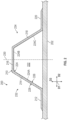
- FIG. 2 is a cross-sectional view of a hat stringer 200.
- the hat stringer can be one of the hat stringers 130 of the aircraft 100 of FIG. 1 , for example.
- a first direction D1 (extending into and out of the page in FIG. 2 ), a second direction D2, and a third direction D3 are defined.
- the first, second, and third directions D1, D2, D3 are mutually perpendicular and form an orthogonal direction system.
- the first direction D1 is a spanwise direction along a wing of an aircraft.
- FIG. 2 depicts a cross section of the hat stringer 200 as viewed along a spanwise direction of a wing.
- the third direction D3 can be a vertical direction.
- the hat stringer 200 is coupled with a skin member 202 to provide support thereto.
- the skin member 202 can be a lower wing skin of a wing, for example.
- the hat stringer 130 includes a base stringer 210.
- the base stringer 210 can be formed of one or more plies, such as one or more Carbon Fiber-Reinforced Polymers (CFRP) plies.
- CFRP Carbon Fiber-Reinforced Polymers
- the base stringer 210 can be formed as a monolithic unitary structure, for example.
- the base stringer 210 has, from left to right in FIG. 2 , a first flange segment 212, a first web segment 214, a cap segment 216, a second web segment 218, and a second flange segment 220.
- the first and second flange segments 212, 220 are coupled with the skin member 202.
- the first and second web segments 214, 218 extend from their respective first and second flange segments 212, 220 and converge toward one another as they extend away from their respective first and second flange segments 212, 220.
- the cap segment 216 connects the first and second web segments 214, 218 and extends parallel (or substantially parallel) to the first and second flange segments 212, 220 and the skin member 202.
- the base stringer 210 and the skin member 202 collectively define an internal cavity 222.
- a profile 224 of the internal cavity 222 is defined by the base stringer 210.
- the profile 224 of the internal cavity 222 as viewed along the first direction D1 is defined by an internal surface 226 of the base stringer 210 (e.g., when in serviceable condition).
- the profile 224 of the internal cavity 222 is represented by a dashed line extending along the internal surface 226 of the base stringer 210, or more specifically, along the internal surfaces of the first and second web segments 214, 218 and the cap segment 216.
- the profile 224 has a first web portion 224A, a cap portion 224B, and a second web portion 224C.
- the first web portion 224A extends along the internal surface of the first web segment 214
- the cap portion 224B extends along the internal surface of the cap segment 216
- the second web portion 224C extends along the internal surface of the second web segment 218.
- the base stringer 210 has an external surface 228 opposite the internal surface 226.
- the hat stringer 200 defines a central plane 230 demarcating a first side 232 and a second side 234 of the hat stringer 200.
- the central plane 230 is orthogonal to the second direction D2.
- a hat stringer such as the hat stringer 200 of FIG. 2
- a segment of the hat stringer 200 may be damaged to an extent that its structural integrity is compromised, or in some extreme cases, missing completely. This may present a safety issue or render the aircraft unfit for service.
- hat stringer repair techniques and repair stringers that facilitate repair or reinforcement of a hat stringer are provided herein. Example restoration techniques and repair stringers are provided below.
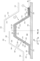
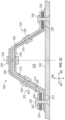
- FIGS. 3A and 3B depict the hat stringer 200 of FIG. 2 undergoing a full stringer restoration with repair stringers having a "lazy Z" shape.
- the base stringer 210 is in the process of undergoing full stringer restoration by using a first repair stringer 300 and a second repair stringer 310, which both have a lazy Z shape.
- the first and second repair stringers 300, 310 can both be formed of one or more plies, such as one or more carbon fiber plies.
- Full stringer restoration can be implemented in response to the base stringer 210 becoming damaged or otherwise structurally unsound.
- the first repair stringer 300 has a flange segment 302, a web segment 304, and a cap segment 306.
- the web segment 304 extends between and connects the cap segment 306 and the flange segment 302.
- the flange segment 302 and the cap segment 306 both extend parallel (or substantially parallel) to one another.
- the first repair stringer 300 has an internal profile 308 that matches at least a portion of the profile 224 of the internal cavity 222 defined by the hat stringer 200.
- the internal profile 308 of the first repair stringer 300 is represented by a dashed line extending along the internal surface of the first repair stringer 300.
- the internal profile 308 of the first repair stringer 300 matches or is shaped complementary to at least a portion of an external surface of the stringer to which the first repair stringer 300 will be arranged adjacent.
- the internal profile 308 of the first repair stringer 300 matches or is shaped complementary to at least a portion of the external surface 228 of the base stringer 210.
- a cross-sectional area of the first repair stringer 300 as viewed along the first direction D1 is less than a total cross-sectional area of the hat stringer 200 as viewed along the first direction D1.
- the first repair stringer 300 can be deemed to have a partial cross section with respect to the hat stringer 200.
- the second repair stringer 310 has a flange segment 312, a web segment 314, and a cap segment 316.
- the web segment 314 extends between and connects the cap segment 316 and the flange segment 312.
- the flange segment 312 and the cap segment 316 both extend parallel (or substantially parallel) to one another.
- the second repair stringer 310 has an internal profile 318 that matches at least a portion of the profile 224 of the internal cavity 222 defined by the hat stringer 200.
- the internal profile 318 of the second repair stringer 310 is represented by a dashed line extending along the internal surface of the second repair stringer 310.
- the internal profile 318 of the second repair stringer 310 matches or is shaped complementary to at least a portion of an external surface of the stringer to which the second repair stringer 310 will be arranged adjacent.
- the internal profile 318 of the second repair stringer 310 matches or is shaped complementary to at least a portion of the external surface 228 of the base stringer 210 and at least a portion of the external surface of the first repair stringer 300.
- a cross-sectional area of the second repair stringer 310 as viewed along the first direction D1 is less than a total cross-sectional area of the hat stringer 200 as viewed along the first direction D1.
- the second repair stringer 310 can be deemed to have a partial cross section with respect to the hat stringer 200.
- the first repair stringer 300 and the second repair stringer 310 have a same cross-sectional shape as viewed along the first direction D1.
- the second repair stringer 310 is oriented so as to be flipped horizontally with respect to the first repair stringer 300, or rather, the second repair stringer 310 is rotated one hundred eighty degrees (180°) about a rotation axis extending along the third direction D3 with respect to the first repair stringer 300.
- the full stringer restoration can be implemented by arranging the first repair stringer 300 in a first mounting location along the cross section of the hat stringer 200.
- the first repair stringer 300 is shown being arranged in a first mounting location as denoted by arrow 1.
- the first repair stringer 300 is arranged so that the flange segment 302, the web segment 304, and the cap segment 306 respectively confront or are respectively positioned adjacent to the first flange segment 212, the first web segment 214, and the cap segment 216 of the base stringer 210.
- the flange segment 302, the web segment 304, and the cap segment 306 of the first repair stringer 300 respectively extend parallel with the first flange segment 212, the first web segment 214, and the cap segment 216 of the base stringer 210 when the first repair stringer 300 is arranged in the first mounting location.
- the full stringer restoration using repair stringers having a "lazy Z" shape can further be implemented by arranging the second repair stringer 310 in a second mounting location along the cross section of the hat stringer 200.
- the second repair stringer 310 is shown being arranged in a second mounting location as denoted by arrow 2.
- the flange segment 312, the web segment 314, and the cap segment 316 of the second repair stringer 310 respectively extend parallel with the second flange segment 220, the second web segment 218, and the cap segment 216 of the base stringer 210 when the second repair stringer 310 is arranged in the second mounting location.
- the second repair stringer 310 is arranged so that the web segment 314 confronts or is positioned adjacent to the second web segment 218 of the base stringer 210 and so that the cap segment 316 confronts or is positioned adjacent to the cap segment 306 of the first repair stringer 300.
- the cap segment 316 of the second repair stringer 310 physically overlaps the cap segment 306 of the first repair stringer 300.
- the cap segment 306 of the first repair stringer 300 and the cap segment 316 of the second repair stringer 310 each extend parallel with the cap segment 216 of the base stringer 210.
- the cap segment 306 of the first repair stringer 300 is sandwiched between the cap segment 316 of the second repair stringer 310 and the cap segment 216 of the base stringer 210, e.g., along the third direction D3.
- the flange segment 312 of the second repair stringer 310 and the second flange segment 220 of the base stringer 210 are spaced from one another, e.g., along the third direction D3. Accordingly, a gap G or vertical offset is defined between the flange segment 312 of the second repair stringer 310 and the second flange segment 220 of the base stringer 210.
- the full stringer restoration using repair stringers having a "lazy Z" shape can further be implemented by placing one or more shims 320 between the second flange segment 220 of the base stringer 210 and the flange segment 312 of the second repair stringer 310.
- one or more shims 320 can be arranged to fill in the gap G.
- the one or more shims 320 are shown being placed within the gap G as denoted by arrow 3.
- the added shims 320 can improve the structural integrity of the restored hat stringer 200.
- the need for shims on both sides of the hat stringer 200 can be eliminated or otherwise reduced.
- no shims are needed between the flange segment 302 of the first repair stringer 300 and the first flange segment 212 of the base stringer 210.
- the full stringer restoration using repair stringers having a "lazy Z" shape can further be implemented by coupling the first repair stringer 300 and the second repair stringer 310 with the base stringer 210 in their respective mounting locations.
- a plurality of fasteners 330 are used to couple the first and second repair stringers 300, 310 with the base stringer 210.
- One of the plurality of fasteners 330 can couple the flange segment 302 of the first repair stringer 300 with the first flange segment 212 of the base stringer 210.
- One of the plurality of fasteners 330 can couple the web segment 304 of the first repair stringer 300 with the first web segment 214 of the base stringer 210.
- One of the plurality of fasteners 330 can couple the cap segment 306 of the first repair stringer 300, the cap segment 316 of the second repair stringer 310, and the cap segment 216 of the base stringer 210 together.
- One of the plurality of fasteners 330 can couple the web segment 314 of the second repair stringer 310 with the second web segment 218 of the base stringer 210.
- one of the plurality of fasteners 330 can couple the flange segment 312 of the second repair stringer 310 with the second flange segment 220 of the base stringer 210.
- Any suitable type of fastener can be utilized, including but not limited to, rivets, bolts, screws, anchors, etc.
- the first and second repair stringers 300, 310 can be coupled with the base stringer 210 in other manners, such as by a combination of compression and thermal processes.
- the hat stringer 200 can be deemed a restored or repaired hat stringer.
- the first mounting location is one of a plurality of possible mounting locations along the cross section of the hat stringer 200 in which the first repair stringer 300 can be arranged.
- the internal profile 308 of the first repair stringer 300 matches the profile 224 of the internal cavity 222 defined by the hat stringer 200.
- the first repair stringer 300 can be arranged so that the flange segment 302, the web segment 304, and the cap segment 306 respectively confront or are respectively positioned adjacent to the second flange segment 220, the second web segment 218, and the cap segment 216 of the base stringer 210.
- the flange segment 302, the web segment 304, and the cap segment 306 of the first repair stringer 300 can respectively extend parallel with the second flange segment 220, the second web segment 218, and the cap segment 216 of the base stringer 210.
- the first repair stringer 300 can be flipped horizontally with respect to its orientation shown in FIGS.
- the first repair stringer 300 can be rotated from its orientation in FIGS. 3A and 3B one hundred eighty degrees (180°) about a rotation axis extending along the third direction D3).
- the internal profile 308 of the first repair stringer 300 would still match the profile 224 of the internal cavity 222 defined by the hat stringer 200.
- the first repair stringer 300 is geometrically shaped to be mountable to the hat stringer 200 at least in a first possible mounting location in which the first repair stringer 300 is positioned primarily on the first side 232 of the hat stringer 200 (i.e., greater than fifty percent (50%) of the cross section of the first repair stringer 300 is positioned on the first side 232) and in a second possible mounting location in which the first repair stringer 300 is positioned primarily on the second side 234 of the hat stringer 200 (i.e., greater than fifty percent (50%) of the cross section of the first repair stringer 300 is positioned on the second side 234).
- the first repair stringer 300 can be arranged so that the flange segment 302, the web segment 304, and the cap segment 306 of the first repair stringer 300 respectively extend parallel with, but do not contact, the first flange segment 212, the first web segment 214, and the cap segment 216 of the base stringer 210 when the first repair stringer 300 is arranged in the second alternative mounting location.
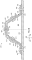
- the first repair stringer 300 is arranged so that the web segment 304 confronts or is positioned adjacent to a first web segment of another repair stringer 340 (e.g., a first existing repair stringer) and so that the cap segment 306 confronts or is positioned adjacent to the cap segment of yet another repair stringer 350 (e.g., a second existing repair stringer).
- the cap segment 306 of the first repair stringer 300 physically overlaps, e.g., the cap segment of the second existing repair stringer 350.
- the internal profile 308 of the first repair stringer 300 would still match the profile 224 of the internal cavity 222 defined by the hat stringer 200.
- the first repair stringer 300 is geometrically shaped to be mountable to the hat stringer 200 in a mounting location in which the first repair stringer 300 is stacked on other stringers (e.g., existing repair stringers) that are not the base stringer 210.
- the first repair stringer 300 can be arranged in the second mounting location, or rather, the mounting location in which the second repair stringer 310 is located in FIGS. 3A and 3B and the second repair stringer 310 can be mounted in another mounting location of a plurality of possible mounting locations. Accordingly, like the first repair stringer 300, the second repair stringer 310 can likewise be mountable in a plurality of possible positions as will be appreciated by the teachings above.
- the web segment 304 of the first repair stringer 300 extends parallel with a web segment of the base stringer 210.
- the internal surface of the web segment 304 of the first repair stringer 300 extends parallel with a web portion of the profile 224.
- the second repair stringer 310 in each of the plurality of possible mounting locations in which the second repair stringer 310 can possibly be mounted, the web segment 314 of the second repair stringer 310 extends parallel with a web segment of the base stringer 210.
- the internal surface of the web segment 314 of the second repair stringer 310 extends parallel with a web portion of the profile 224.
- the cap segment 306 of the first repair stringer 300 extends parallel with the cap segment 216 of the base stringer 210 and the flange segment 302 of the first repair stringer 300 extends parallel with a flange segment of the base stringer 210.
- the second repair stringer 310 the cap segment 316 of the second repair stringer 310 extends parallel with the cap segment 216 of the base stringer 210 and the flange segment 312 of the second repair stringer 310 extends parallel with a flange segment of the base stringer 210.
- Restoring a hat stringer with one or more repair stringers each having a lazy Z cross-sectional shape can present certain advantages.
- the partial cross section of the lazy Z shape allows for repair stringers to be mounted in a plurality of mounting locations along the cross section of the hat stringer, which provides flexibility in the repair process.
- the shimming needed for the repair can be reduced compared to conventional techniques.
- shims 320 are needed on only one side of the hat stringer as the flange segment 302 of the first repair stringer 300 can be arranged directly on or adjacent the first flange segment 212 of the base stringer 210.
- a repair stringer having a lazy Z cross-sectional shape includes three segments that are capable of contacting three corresponding segments of one or more other stringers. The three points of contact can provide structural stability to a repaired hat stringer.
- a restoration of a hat stringer with a plurality of lazy Z-shaped repair stringers is advantageous in that such hat stringers can be stacked (e.g., as shown in FIG. 3C ) without need to change the shape or angle of the repair stringers, which can greatly reduce or eliminate the need for custom repair stringers for a stacked arrangement.
- a plurality of same shaped lazy Z repair stringers can be used for a stacked repair. Such an advantage can improve the ease of performing the repair process for operators and stocking and storing repair parts, among other benefits.
- FIGS. 4A and 4B depict the hat stringer 200 of FIG. 2 undergoing a full stringer restoration with repair stringers having a "lazy L" shape.
- the base stringer 210 is in the process of undergoing full stringer restoration by using a first repair stringer 400, a second repair stringer 410, a third repair stringer 420, and a fourth repair stringer 430, which all have a lazy L shape, or rather, a lazy L cross section as viewed along the first direction D1.
- the first, second, third, and fourth repair stringers 400, 410, 420, 430 can each be formed of one or more plies, such as one or more carbon fiber plies.
- Full stringer restoration can be implemented in response to the base stringer 210 becoming damaged or otherwise structurally unsound.
- the first, second, third, and fourth repair stringers 400, 410, 420, 430 each include a web segment and a second segment, which can be flange segment or a cap segment depending on the orientation of the repair stringer.
- the second segment of a given repair stringer is non-parallel with its web segment.
- An obtuse angle is defined between the web segment and the second segment of respective ones of the first, second, third, and fourth repair stringers 400, 410, 420, 430.
- the first repair stringer 400 has a web segment 404 and a second segment, which is a flange segment 402 in this and certain other examples.
- the second repair stringer 410 has a web segment 414 and a second segment, which is a cap segment 416 in this and certain other examples.
- the third repair stringer 420 has a web segment 424 and a second segment, which is a flange segment 422 in this and certain other examples.
- the fourth repair stringer 430 has a web segment 434 and a second segment, which is a cap segment 436 in this and certain other examples.
- the first repair stringer 400 has an internal profile 408 that matches at least a portion of the profile 224 of the internal cavity 222 defined by the hat stringer 200.
- the internal profile 408 of the first repair stringer 400 is represented by a dashed line extending along the internal surface of the first repair stringer 400.
- the internal profile 408 of the first repair stringer 400 matches or is shaped complementary to at least the first web portion 224A of the profile 224.
- the internal profile 408 of the first repair stringer 400 matches or is shaped complementary to at least a portion of an external surface of the stringer (or stringers) to which the first repair stringer 400 will be arranged adjacent.
- the internal profile 408 of the first repair stringer 400 matches or is shaped complementary to at least a portion of the external surface 228 of the base stringer 210.
- the second repair stringer 410 has an internal profile 418 that matches at least a portion of the profile 224 of the internal cavity 222 defined by the hat stringer 200.
- the internal profile 418 of the second repair stringer 410 is represented by a dashed line extending along the internal surface of the second repair stringer 410.
- the internal profile 418 of the second repair stringer 410 matches or is shaped complementary to at least the first web portion 224A and the cap portion 224B of the profile 224.
- the internal profile 418 of the second repair stringer 410 matches or is shaped complementary to at least a portion of an external surface of the stringer (or stringers) to which the second repair stringer 410 will be arranged adjacent.
- the internal profile 418 of the second repair stringer 410 matches or is shaped complementary to at least a portion of the external surface 228 of the base stringer 210 along the cap segment 216 and to at least a portion of the external surface of the first repair stringer 400.
- the third repair stringer 420 has an internal profile 428 that matches at least a portion of the profile 224 of the internal cavity 222 defined by the hat stringer 200.
- the internal profile 428 of the third repair stringer 420 is represented by a dashed line extending along the internal surface of the third repair stringer 420.
- the internal profile 428 of the third repair stringer 420 matches or is shaped complementary to at least the second web portion 224C of the profile 224.
- the internal profile 428 of the third repair stringer 420 matches or is shaped complementary to at least a portion of an external surface of the stringer (or stringers) to which the third repair stringer 420 will be arranged adjacent.
- the internal profile 428 of the third repair stringer 420 matches or is shaped complementary to at least a portion of the external surface 228 of the base stringer 210.
- the fourth repair stringer 430 has an internal profile 438 that matches at least a portion of the profile 224 of the internal cavity 222 defined by the hat stringer 200.
- the internal profile 438 of the fourth repair stringer 430 is represented by a dashed line extending along the internal surface of the fourth repair stringer 430.
- the internal profile 438 of the fourth repair stringer 430 matches or is shaped complementary to at least the second web portion 224C and the cap portion 224B of the profile 224.
- the internal profile 438 of the fourth repair stringer 430 matches or is shaped complementary to at least a portion of an external surface of the stringer (or stringers) to which the fourth repair stringer 430 will be arranged adjacent.
- the internal profile 438 of the fourth repair stringer 430 matches or is shaped complementary to at least a portion of the external surface of the third repair stringer 420 and to at least a portion of the external surface of the second repair stringer 410.
- a cross-sectional area of the first repair stringer 400 as viewed along the first direction D1 is less than a total cross-sectional area of the hat stringer 200 as viewed along the first direction D1.
- the second, third, and fourth repair stringers 410, 420, 430 can each be deemed to have a partial cross section with respect to the hat stringer 200.
- the first, second, third, and fourth repair stringers 400, 410, 420, 430 can each have a same cross-sectional shape as one another as viewed along the first direction D1.
- the second repair stringer 410 is oriented so as to be flipped vertically with respect to the first repair stringer 400, or rather, the second repair stringer 410 is rotated one hundred eighty degrees (180°) about a rotation axis extending along the second direction D2 with respect to the first repair stringer 400.
- the third repair stringer 420 is oriented so as to be flipped horizontally with respect to the first repair stringer 400, or rather, the third repair stringer 420 is rotated one hundred eighty degrees (180°) about a rotation axis extending along the third direction D3 with respect to the first repair stringer 400.
- the fourth repair stringer 430 is oriented so as to be flipped vertically and horizontally with respect to the first repair stringer 400, or rather, the fourth repair stringer 430 is rotated one hundred eighty degrees (180°) about a rotation axis extending along the third direction D3 with respect to the first repair stringer 400 for the horizontal flip and the fourth repair stringer 430 is rotated one hundred eighty degrees (180°) about a rotation axis extending along the second direction D2 with respect to the first repair stringer 400 for the vertical flip.
- the full stringer restoration can be implemented by arranging the first repair stringer 400 in a first mounting location along the cross section of the hat stringer 200.
- the first repair stringer 400 is shown being arranged in a first mounting location as denoted by arrow 1.
- the first repair stringer 400 is arranged so that the flange segment 402 and the web segment 404 respectively confront or are respectively positioned adjacent to the first flange segment 212 and the first web segment 214 of the base stringer 210.
- the flange segment 402 and the web segment 404 of the first repair stringer 400 respectively extend parallel with the first flange segment 212 and the first web segment 214 of the base stringer 210 when the first repair stringer 400 is arranged in the first mounting location.
- the full stringer restoration using repair stringers having a "lazy L" shape can further be implemented by arranging the second repair stringer 410 in a second mounting location along the cross section of the hat stringer 200.
- the second repair stringer 410 is shown being arranged in a second mounting location as denoted by arrow 2.
- the second repair stringer 410 is arranged so that the web segment 414 and the cap segment 416 of the second repair stringer 410 respectively extend parallel with the first web segment 214 and the cap segment 216 of the base stringer 210.
- the second repair stringer 410 is arranged so that the web segment 414 confronts or is positioned adjacent to the web segment 404 of the first repair stringer 400.
- the web segment 414 of the second repair stringer 410 physically overlaps the web segment 404 of the first repair stringer 400, with the web segment 404 being sandwiched or positioned between the web segment 414 and the first web segment 214 of the base stringer 210.
- the second repair stringer 410 is arranged so that the cap segment 416 confronts or is positioned adjacent to the cap segment 216 of the base stringer 210.
- the full stringer restoration using repair stringers having a "lazy L" shape can further be implemented by arranging the third repair stringer 420 in a third mounting location along the cross section of the hat stringer 200.
- the third repair stringer 420 is shown being arranged in a third mounting location as denoted by arrow 3.
- the third repair stringer 420 is arranged so that the flange segment 422 and the web segment 424 respectively confront or are respectively positioned adjacent to the second flange segment 220 and the second web segment 218 of the base stringer 210.
- the flange segment 422 and the web segment 424 of the third repair stringer 420 respectively extend parallel with the second flange segment 220 and the second web segment 218 of the base stringer 210 when the third repair stringer 420 is arranged in the third mounting location.
- the full stringer restoration using repair stringers having a "lazy L" shape can further be implemented by arranging the fourth repair stringer 430 in a fourth mounting location along the cross section of the hat stringer 200.
- the fourth repair stringer 430 is shown being arranged in a fourth mounting location as denoted by arrow 4.
- the fourth repair stringer 430 is arranged so that the web segment 434 and the cap segment 436 of the fourth repair stringer 430 respectively extend parallel with the second web segment 218 and the cap segment 216 of the base stringer 210.
- the fourth repair stringer 430 is arranged so that the web segment 434 confronts or is positioned adjacent to the web segment 424 of the third repair stringer 420.
- the web segment 434 of the fourth repair stringer 430 physically overlaps the web segment 424 of the third repair stringer 420, with the web segment 424 being sandwiched or positioned between the web segment 434 and the second web segment 218 of the base stringer 210.
- the fourth repair stringer 430 is arranged so that the cap segment 436 confronts or is positioned adjacent to the cap segment 416 of the second repair stringer 410.
- the cap segment 436 of the fourth repair stringer 430 is spaced from the cap segment 216 of the base stringer 210, e.g., along the third direction D3.
- the full stringer restoration using repair stringers having a "lazy L" shape can further be implemented by coupling the first, second, third, and fourth repair stringers 400, 410, 420, 430 with the base stringer 210 in their respective mounting locations.
- a plurality of fasteners 440 are used to couple the first, second, third, and fourth repair stringers 400, 410, 420, 430 with the base stringer 210.
- One of the plurality of fasteners 440 can couple the flange segment 402 of the first repair stringer 400 with the first flange segment 212 of the base stringer 210.
- One of the plurality of fasteners 440 can couple the web segment 404 of the first repair stringer 400, the web segment 414 of the second repair stringer 410, and the first web segment 214 of the base stringer 210.
- One of the plurality of fasteners 440 can couple the cap segment 416 of the second repair stringer 410, the cap segment 436 of the third repair stringer 430, and the cap segment 216 of the base stringer 210.
- One of the plurality of fasteners 440 can couple the web segment 424 of the third repair stringer 420, the web segment 434 of the fourth repair stringer 430, and the second web segment 218 of the base stringer 210.
- one of the plurality of fasteners 440 can couple the flange segment 422 of the third repair stringer 420 with the second flange segment 220 of the base stringer 210.
- Any suitable type of fastener can be utilized, including but not limited to, rivets, bolts, screws, anchors, etc.
- the first, second, third, and/or fourth repair stringers 400, 410, 420, 430 can be coupled with the base stringer 210 in other manners, such as by a combination of compression and thermal processes.
- the hat stringer 200 can be deemed a restored or repaired hat stringer.
- the first mounting location is one of a plurality of possible mounting locations along the cross section of the hat stringer 200 in which the first repair stringer 400 can be arranged.
- the internal profile 408 of the first repair stringer 400 matches at least a portion of the profile 224 of the internal cavity 222 defined by the hat stringer 200.
- the first repair stringer 400 can be flipped vertically and/or horizontally to be mounted in any one of the mounting locations in which the second, third, and/or fourth repair stringers are shown in FIGS.
- the internal profile of the first repair stringer 400 matches or is shaped complementary to at least a portion of the profile 224 of the internal cavity 222.
- the second repair stringer 410, the third repair stringer 420, and the fourth repair stringer 430 are mountable in a plurality of mounting locations along the cross section of the hat stringer 200.
- a hat stringer with one or more repair stringers each having a lazy L cross-sectional shape can present certain advantages.
- the partial cross section of the lazy L shape allows for repair stringers to be mounted in a plurality of mounting locations along the cross section of the hat stringer, which provides flexibility in the repair process.
- the shimming needed for the repair can be eliminated or otherwise significantly reduced. For example, in FIG. 4B , no shimming is needed to restore the hat stringer.
- a repair stringer having a lazy L cross-sectional shape includes two segments that are capable of contacting two corresponding segments of one or more other stringers. The two points of contact can provide structural stability to a repaired hat stringer.
- a restoration of a hat stringer with a plurality of lazy L-shaped repair stringers is advantageous in that such hat stringers can be stacked without need to change the shape or angle of the repair stringers, which can greatly reduce or eliminate the need for custom repair stringers for a stacked arrangement.
- Such an advantage can improve the ease of performing the repair process for operators and stocking and storing repair parts, among other benefits.
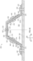
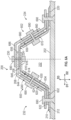
- FIG. 4C is a cross-sectional view of another hat stringer undergoing a full stringer restoration with repair stringers having a "lazy Z" shape and one repair stringer having a "lazy U” shape.
- the base stringer 210 is in the process of undergoing full stringer restoration by using a first repair stringer 400, a second repair stringer 420 (configured and oriented in a similar manner as the third repair stringer 420 of FIGS. 4A and 4B ), and a third repair stringer 450.
- the first and second repair stringers 400, 420 both have a lazy L shape, or rather, a lazy L cross section as viewed along the first direction D1.
- the third repair stringer 450 has a lazy U shape, or rather, a lazy U cross section as viewed along the first direction D1.
- the third repair stringer 450 can be arranged in an upside orientation or as an upside-down lazy U, e.g., as shown in FIG. 4C .
- the first, second, and third repair stringers 400, 420, 450 can each be formed of one or more plies, such as one or more carbon fiber plies. Full stringer restoration can be implemented in response to the base stringer 210 becoming damaged or otherwise structurally unsound.
- the first and second repair stringers 400, 420 can be arranged as described above with reference to FIGS. 4A and 4B .
- the third repair stringer 450 includes a first web segment 454, a cap segment 456, and a second web segment 458.
- the cap segment 456 extends between and connects the first web segment 454 and the second web segment 458.
- a first obtuse angle is defined between the first web segment 454 and the cap segment 456.
- a second obtuse angle is defined between the second web segment 458 and the cap segment 456.
- the third repair stringer 450 does not include flange segments.
- the third repair stringer 450 has an internal profile 460 that matches at least a portion of the profile 224 of the internal cavity 222 defined by the hat stringer 200.
- the internal profile 460 of the third repair stringer 450 is represented by a dashed line extending along the internal surface of the third repair stringer 450.
- the internal profile 460 of the third repair stringer 450 matches or is shaped complementary to the first web portion 224A, the cap portion 224B, and the second web portion 224C of the profile 224.
- the internal profile 460 of the third repair stringer 450 matches or is shaped complementary to an external surface of the stringer (or stringers) to which the third repair stringer 450 will be arranged adjacent.
- the internal profile 460 of the third repair stringer 450 matches or is shaped complementary to at least a portion of the external surface of the first repair stringer 400, at least a portion of the external surface of the baseline stringer 210, and at least a portion of the external surface of the second repair stringer 420.
- a repair stringer having a lazy U shape can be arranged so that a first web segment thereof couples to a web segment of one repair stringer, a cap segment thereof couples to and spans the full length of a cap segment of a baseline stringer, and a second web segment thereof couples to a web segment of another repair stringer.
- Such an arrangement can provide advantageous structurally integrity at the cap and web segments of the repaired hat stringer, among other benefits.
- FIG. 5 depicts the hat stringer 200 of FIG. 2 undergoing a partial stringer restoration with at least one repair stringer having a "lazy L" shape.
- the base stringer 210 is in the process of undergoing partial stringer restoration by using a single repair stringer (in this example a first repair stringer 500), which has a lazy L shape, or rather, a lazy L cross section as viewed along the first direction D1.
- the first repair stringer 500 can be formed of one or more plies, such as one or more carbon fiber plies.
- Partial stringer restoration can be implemented in response to the base stringer 210 becoming damaged or otherwise structurally unsound, e.g., as represented by a damaged portion 204 in FIG. 5 .
- the damaged portion 204 is located at the transition between the first flange segment 212 and the first web segment 214 in this and certain other examples but may be located in other areas along the cross section of the hat stringer 200 in other instances.
- a repair stringer having a "lazy Z" shape can be used for a partial stringer restoration.
- the first repair stringer 500 includes a first segment (e.g., a web segment) and a second segment, which can be flange segment or a cap segment depending on the orientation of the first repair stringer 500.
- the second segment of the first repair stringer 500 is non-parallel with its first segment.
- An obtuse angle is defined between the first segment and the second segment of the first repair stringer 500.
- the first segment of the first repair stringer 500 is a web segment 504 and the second segment is a flange segment 502.
- the first repair stringer 500 has an internal profile 508 that matches at least a portion of the profile 224 of the internal cavity 222 defined by the hat stringer 200.
- the internal profile 508 of the first repair stringer 500 is represented by a dashed line extending along the internal surface of the first repair stringer 500.
- the internal profile 508 of the first repair stringer 500 matches or is shaped complementary to at least the first web portion 224A of the profile 224.
- the internal profile 508 of the first repair stringer 500 matches or is shaped complementary to at least a portion of an external surface of the stringer (or stringers) to which the first repair stringer 500 will be arranged adjacent. For instance, as depicted in FIG.
- the internal profile 508 of the first repair stringer 500 matches or is shaped complementary to at least a portion of the external surface 228 of the base stringer 210. Further, in the depicted example of FIG. 5 , a cross-sectional area of the first repair stringer 500 as viewed along the first direction D1 (e.g., a spanwise direction of a wing) is less than a total cross-sectional area of the hat stringer 200 as viewed along the first direction D1.
- the partial stringer restoration can be implemented by arranging the first repair stringer 500 in a first mounting location along the cross section of the hat stringer 200.
- the first repair stringer 500 is shown being arranged in a first mounting location as denoted by arrow 1.
- the first repair stringer 500 is arranged so that the flange segment 502 and the web segment 504 respectively confront or are respectively positioned adjacent to the first flange segment 212 and the first web segment 214 of the base stringer 210.
- the flange segment 502 and the web segment 504 of the first repair stringer 500 respectively extend parallel with the first flange segment 212 and the first web segment 214 of the base stringer 210 when the first repair stringer 500 is arranged in the first mounting location.
- the partial stringer restoration using a repair stringer having a "lazy L" shape can further be implemented by coupling the first repair stringer 500 with the base stringer 210 in the first mounting location.
- a plurality of fasteners 520 are used to couple the first repair stringer 500 with the base stringer 210.
- One of the plurality of fasteners 520 can couple the flange segment 502 of the first repair stringer 500 with the first flange segment 212 of the base stringer 210.
- One of the plurality of fasteners 520 can couple the web segment 504 of the first repair stringer 500 and the first web segment 214 of the base stringer 210.
- the first repair stringer 500 can be coupled with the base stringer 210 in other manners, such as by a combination of compression and thermal processes. With the first repair stringer 500 coupled with the base stringer 210 as depicted in FIG. 5 , the hat stringer 200 can be deemed a restored or repaired hat stringer.
- the first mounting location is one of a plurality of possible mounting locations along the cross section of the hat stringer 200 in which the first repair stringer 500 can be arranged.
- the internal profile 508 of the first repair stringer 500 matches at least a portion of the profile 224 of the internal cavity 222 defined by the hat stringer 200.
- the first repair stringer 500 can be flipped vertically and/or horizontally to be mounted in another possible mounting location.
- the first repair stringer 500 can be flipped horizontally and arranged so that the web segment 504 and the flange segment 502 are respectively aligned parallel with the second web segment 218 and the second flange segment 220 of the base stringer 210, e.g., to restore damage to a transition between the second web segment 218 and the second flange segment 220 of the base stringer 210.
- the first repair stringer 500 can be flipped vertically and arranged so that the web segment 504 and its second segment are respectively aligned parallel with the first web segment 214 and the cap segment 216 of the base stringer 210, e.g., to restore damage to a transition between the first web segment 214 and the cap segment 216 of the base stringer 210.
- the first repair stringer 500 can be flipped both vertically and horizontally and arranged so that the web segment 504 and its second segment are respectively aligned parallel with the second web segment 218 and the cap segment 216 of the base stringer 210, e.g., to restore damage to a transition between the second web segment 218 and the cap segment 216 of the base stringer 210.
- the internal profile of the first repair stringer 500 matches or is shaped complementary to at least a portion of the profile 224 of the internal cavity 222.
- Partially restoring a hat stringer with a repair stringer disclosed herein can present certain advantages.
- the repair stringers of the present disclosure have a partial cross section with respect to the total cross section of the hat stringer, which allows for a repair stringer to be strategically arranged or localized to the damaged section of the hat stringer. This allows for less material to be used for the repair, which may advantageously reduce the weight of the aircraft.
- FIG. 6A depicts the hat stringer 200 of FIG. 2 undergoing a splice restoration with repair stringers having a "lazy L" shape.
- the base stringer 210 is in the process of undergoing a splice restoration by plurality of strategically arranged and oriented repair stringers, including a first set 600 of repair stringers arranged primarily at the first side 232 and a second set 602 of repair stringers arranged primarily at the second side 234 of the hat stringer 200 in need of splice restoration.
- the first set 600 includes a first repair stringer 610, a second repair stringer 620, a third repair stringer 630, and a fourth repair stringer 640.
- the first, second, third, and fourth repair stringers 610, 620, 630, 640 are each shaped to have an internal profile that matches at least a portion of the profile 224 of the internal cavity 222 defined by the hat stringer 200, regardless of their respective mounting positions or orientations.
- the first, second, third, and fourth repair stringers 610, 620, 630, 640 all have a same cross-sectional shape as one another, e.g., as viewed along the first direction D1, which can be a spanwise direction along a wing of an aircraft.
- the second set 602 includes a first repair stringer 650, a second repair stringer 660, a third repair stringer 670, and a fourth repair stringer 680.
- the repair stringers 610, 620, 630, 640, 650, 660, 670, 680 (or 610-680) can each be formed of one or more plies, such as one or more carbon fiber plies.
- the first, second, third, and fourth repair stringers 650, 660, 670, 680 are each shaped to have an internal profile that matches at least a portion of the profile 224 of the internal cavity 222 defined by the hat stringer 200, regardless of their respective mounting positions or orientations.
- first, second, third, and fourth repair stringers 650, 660, 670, 680 all have a same cross-sectional shape as one another, e.g., as viewed along the first direction D1, which can be a spanwise direction along a wing of an aircraft.
- a splice restoration can be implemented in response to the base stringer 210 becoming damaged with a missing section, such as the missing section 206 depicted in FIG. 6A .
- a missing section such as the missing section 206 depicted in FIG. 6A .
- the first web segment, the cap segment, and the second web segment of the base stringer 210 are missing and thus collectively form the missing section 206 or void in the base stringer 210.
- a plane 208 can be defined where the missing section 206 of the base stringer 210 was previously positioned. The plane 208 is defined by dashed lines in FIG. 6A .
- the splice restoration can be implemented by constructing the first set 600 of repair stringers.
- constructing the first set 600 can include arranging the first repair stringer 610 so that a segment (e.g., a web segment 614) of the first repair stringer 610 is positioned in or adjacent the plane 208 where the missing section 206 of the base stringer 210 was previously positioned.
- the web segment 614 of the first repair stringer 610 is positioned, at least in part, in the plane 208 where the first web segment of the base stringer 210 was previously positioned.
- Constructing the first set 600 can further include arranging the second repair stringer 620 and the third repair stringer 630 so that segments of the second repair stringer 620 and the third repair stringer 630 (e.g., a web segment 624 of the second repair stringer 620 and a web segment 634 of the third repair stringer 630) sandwich the segment (e.g., a web segment 614) of the first repair stringer 610 positioned within the plane 208.
- the third repair segment 630 has a flange segment 632 that confronts or is positioned adjacent to the first flange segment 212 of the base stringer 210.
- the second repair segment 620 has a flange segment 622 that confronts or is positioned adjacent to the flange segment 632 of the third repair segment 630.
- the flange segments 622, 632 are arranged relative to the first flange segment 212 so that a space or gap is defined between the web segments 624, 634.
- the gap between the web segments 624, 634 is sized so that the web segment 614 of the first repair segment 610 can be received therein, or rather, so that the web segment 614 can be sandwiched therebetween. Positioning the web segment 614 between the web segments 624, 634 can advantageously enhance the structural integrity of the hat stringer 200.
- Constructing the first set 600 of repair stringers along the first side 232 can further include arranging the fourth repair stringer 640 so that a segment (e.g., a web segment 644) of the fourth repair stringer 640 and a segment (e.g., the web segment 614) of the first repair stringer 610 sandwich the second repair stringer 620 (e.g., the web segment 624.
- the first repair stringer 610 and the fourth repair stringer 640 are arranged so as to define a space or gap between their respective web segments 614, 644.
- the gap between the web segments 614, 644 is sized so that the web segment 624 of the second repair segment 620 can be received therein, or rather, so that the web segment 624 can be sandwiched therebetween. Positioning the web segment 624 between the web segments 614, 644 can advantageously enhance the structural integrity of the hat stringer 200.
- the second and third repair stringers 620, 630 have a same mounting orientation and the first and fourth repair stringers 610, 640 have a same mounting orientation.
- the second and third repair stringers 620, 630 are oriented so as to be flipped vertically and horizontally with respect to the first and fourth repair stringers 610, 640.
- Constructing the first set 600 of repair stringers along the first side 232 can further include coupling the first, second, third, and fourth repair stringers 610, 620, 630, 640 with the base stringer 210.
- a plurality of fasteners 690 are used to couple the first, second, third, and fourth repair stringers 610, 620, 630, 640 of the first set 600 with the base stringer 210.
- One of the plurality of fasteners 690 can couple the flange segment 622 of the second repair stringer 620 and the flange segment 632 of the third repair stringer 630 with the first flange segment 212 of the base stringer 210.
- One of the plurality of fasteners 690 can couple the web segments 614, 624, 634, 644 of the first, second, third, and fourth repair stringers 610, 620, 630, 640.
- the first and fourth repair stringers 610, 640 are coupled with the second and third repair stringers 620, 630, which are coupled with the base stringer 210
- the first and fourth repair stringers 610, 640 are consequently also coupled with the base stringer 210.
- Any suitable type of fastener can be utilized, including but not limited to, rivets, bolts, screws, anchors, etc.
- the first, second, third, and/or fourth repair stringers 610, 620, 630, 640 of the first set 600 can be coupled with the base stringer 210 in other manners, such as by a combination of compression and thermal processes.
- the first set 600 With the first, second, third, and/or fourth repair stringers 610, 620, 630, 640 of the first set 600 arranged in place and coupled with the base stringer 210, the first set 600 can be deemed to repair the first web segment and a first portion of the cap segment of the base stringer 210.
- the splice restoration can further be implemented by constructing the second set 602 of repair stringers.
- constructing the second set 602 can include arranging the first, second, third, and fourth repair stringers 650, 660, 670, 680 as described above with respect to the first set 600, and also coupling them to the base stringer 210, e.g., to the second flange segment 220 thereof.
- a gap is defined between their respective cap segments 616, 646.
- the gap defined between the cap segments 616, 646 is arranged along the plane 208 of where the missing section 206 of the base stringer 210 was previously positioned.
- the gap is sized (e.g., along the third direction D3) so as to be capable of receiving a portion of another repair stringer, e.g., a cap segment 656 of the first repair stringer 650 from the second set 602 as shown in FIG. 6A .
- a gap is defined between their respective cap segments 656, 686.
- the gap defined between the cap segments 616, 646 is arranged along the plane 208 of where the missing section 206 of the base stringer 210 was previously positioned.
- the gap is sized (e.g., along the third direction D3) so as to be capable of receiving a portion of another repair stringer, e.g., the cap segment 646 of the fourth repair stringer 640 from the first set 600 as shown in FIG. 6A .
- an internal surface of the cap segment 686 of the fourth repair stringer 680 of the second set 602 confronts or is positioned adjacent to an external surface of the cap segment 646 of the fourth repair stringer 640 of the first set 600.
- the cap segment 686 of the fourth repair stringer 680 of the second set 602 physically overlaps the cap segment 646 of the fourth repair stringer 640 of the first set 600.
- the cap segment 646 of the fourth repair stringer 640 of the first set 600 physically overlaps the cap segment 656 of the first repair stringer 650 of the second set 602.
- the cap segment 656 of the first repair stringer 650 of the second set 602 physically overlaps the cap segment 616 of the first repair stringer 610 of the first set 600.
- the cap segments 616, 656, 646, 686 of each of the repair stringers 610, 650, 640, 680 extend from their primary sides across the central plane 230.
- the first repair segment 610 is primarily positioned on the first side 232 of the hat stringer 200 but an end of the cap segment 616 extends across the central plane 230 to the second side 234.
- the first repair segment 650 is primarily positioned on the second side 234 of the hat stringer 200 but an end of the cap segment 656 extends across the central plane 230 to the first side 232.
- the fourth repair segment 640 is primarily positioned on the first side 232 of the hat stringer 200 but an end of the cap segment 646 extends across the central plane 230 to the second side 234.
- the fourth repair segment 680 is primarily positioned on the second side 234 of the hat stringer 200 but an end of the cap segment 686 extends across the central plane 230 to the first side 232.
- One of the plurality of fasteners 690 can couple the cap segments 616, 656, 646, 686 as shown in FIG. 6A , which couples the first set 600 with the second set 602.
- the second set 602 can be deemed to repair the second web segment and a second portion of the cap segment of the base stringer 210.
- the first and second sets 600, 602 coupled together as noted above the first flange segment 212 and the second flange segment 220 can be deemed to be spliced together to complete the splice restoration.
- a hat stringer can undergo a splice restoration with only a single set of repair stringers, such as a set of "lazy Z" repair stringers.
- a single set of repair stringers such as a set of "lazy Z" repair stringers.
- the first set 600 of repair stringers is shown being utilized to repair the first web segment and a portion of the cap segment 216 that is missing from the cross section of the hat stringer 200.
- the base stringer 210 is not damaged or otherwise structurally compromised. Accordingly, in the example of FIG. 6B , a second set of repair stringers (e.g., the second set 602 of FIG. 6A ) is not needed to complete the splice restoration.
- a hat stringer can undergo a full, partial, or splice restoration using at least one lazy Z-shaped repair stringer and at least one lazy L-shaped repair stringer.
- a repair stringer that can be used to repair or restore a hat stringer according to any of the techniques disclosed herein.
- the repair stringer can include a web segment.
- the web segment has an internal profile shaped to match a web portion of a profile of an internal cavity defined by a hat stringer.
- the repair stringer can further include at least one of a cap segment and a flange segment extending from the web segment.
- the repair stringer can have a partial cross section with respect to a total cross section of the hat stringer.
- the repair stringer can be mounted in a plurality of possible mounting locations along the cross section of the hat stringer, e.g., as viewed along a spanwise direction of the hat stringer.
- the repair stringer is shaped to have an internal profile that matches at least a portion of a profile of an internal cavity defined by the hat stringer.
- the repair stringer can be formed of one or more plies, such as one or more Carbon Fiber-Reinforced Polymers (CFRP) plies. Examples of such a repair stringer are provided in the examples of FIGS. 3A and 3B , FIG. 3C , FIGS. 4A and 4B , FIG. 5 , and FIGS. 6A and 6B .
- CFRP Carbon Fiber-Reinforced Polymers
- a hat stringer or rather a repaired or restored hat stringer, is provided.
- the hat stringer includes a stringer, such as a base stringer or an existing repair stringer.
- the hat stringer further includes at least one repair stringer coupled with the stringer.
- the repair stringer is coupled with the stringer in a mounting location that is one of a plurality of possible mounting locations along a cross section of the hat stringer, and in each of the plurality of possible mounting locations, the repair stringer is shaped to have an internal profile that matches at least a portion of a profile of an internal cavity defined by the hat stringer.
- a cross-sectional area of the repair stringer is less than a total cross-sectional area of the hat stringer. Examples of such a repaired hat stringer are provided in the examples of FIG. 3B , FIG. 3C , FIG. 4B , FIG. 5 , and FIG. 6B .
- a repaired hat stringer can include at least one lazy Z repair hat stringer and at least one lazy L repair stringer.
- FIG. 7 provides a flow chart for a method 700 of repairing a hat stringer, such as a hat stringer of an aircraft wing.
- the method 700 includes arranging a repair stringer in a mounting location that is one of a plurality of possible mounting locations along a cross section of a hat stringer, and in each of the plurality of possible mounting locations, at least a portion of an internal profile of the repair stringer matches at least a portion of a profile of an internal cavity defined by the hat stringer, and wherein a cross-sectional area of the repair stringer as viewed along a first direction is less than a total cross-sectional area of the hat stringer as viewed along the first direction.
- the repair stringer can be deemed to have a partial cross section with respect to the hat stringer.
- the repair stringer can be arranged relative to a base stringer and/or another stringer, such as another repair stringer.
- the repair stringer in each of the plurality of possible mounting locations, has one segment that extends parallel with a cap segment of the stringer and one segment that extends parallel with a flange segment of the stringer. Stated another way, in each of the plurality of possible mounting locations, the repair stringer has one segment that extends parallel with a cap portion of the profile of the internal cavity and one segment that extends parallel with a flange segment of the stringer.
- the hat stringer defines a central plane demarcating a first side and a second side of the hat stringer.
- the plurality of possible mounting locations include a first possible mounting location in which the repair stringer is positioned primarily on the first side of the hat stringer and a second possible mounting location in which the repair stringer is positioned primarily on the second side of the hat stringer.
- the repair stringer is shaped to be mountable to the first side or to the second side of the hat stringer, and regardless of whether the repair stringer is mounted in the first possible mounting location or the second possible mounting location, at least a portion of the internal profile of the repair stringer matches at least a portion of the profile of the internal cavity defined by the hat stringer.
- the repair stringer has a cap segment, a flange segment, and a web segment extending between and connecting the cap segment and the flange segment.
- the repair stringer can have a "lazy Z" cross section.
- the cap segment, the web segment, and the flange segment of the repair stringer respectively extend parallel with a cap segment, a web segment, and a flange segment of the stringer.
- the cap segment, the web segment, and the flange segment of the repair stringer respectively extend parallel with a cap portion of the profile of the internal cavity, a web portion of the profile of the internal cavity, and a flange segment of a flange segment of the stringer.
- the plurality of possible mounting locations include at least four possible mounting locations.
- the hat stringer can define a central plane demarcating a first side and a second side of the hat stringer, and the at least four possible mounting locations can include at least two possible mounting locations in which the repair stringer is positioned primarily on the first side of the hat stringer and at least two possible mounting locations in which the repair stringer is positioned primarily on the second side of the hat stringer.
- the at least two possible mounting locations in which the repair stringer is positioned primarily on the first side of the hat stringer include a first mounting location and a second mounting location, and in the first mounting location, one segment of the repair stringer extends parallel with a first flange segment of the stringer and one segment of the repair stringer extends parallel with a first web segment of the stringer, and in the second mounting location, one segment of the repair stringer extends parallel with a cap segment of the stringer and one segment of the repair stringer extends parallel with the first web segment of the stringer.
- the at least two possible mounting locations in which the repair stringer is positioned primarily on the second side of the hat stringer include a first mounting location and a second mounting location, and in the first mounting location on the second side, one segment of the repair stringer extends parallel with a cap segment of the stringer and one segment of the repair stringer extends parallel with the second web segment of the stringer, and in the second mounting location on the second side, one segment of the repair stringer extends parallel with a second flange segment of the stringer and one segment of the repair stringer extends parallel with a second web segment of the stringer.
- the stringer includes a first flange segment, a first web segment, a cap segment, a second web segment, and a second flange segment, and wherein the plurality of possible mounting locations along the cross section of the hat stringer include a first mounting location, a second mounting location, a third mounting location, and a fourth mounting location.
- the first mounting location one segment of the repair stringer extends parallel with the first flange segment of the stringer and one segment of the repair stringer extends parallel with a first web segment of the stringer.
- one segment of the repair stringer extends parallel with the cap segment of the stringer and one segment of the repair stringer extends parallel with the first web segment of the stringer.
- one segment of the repair stringer extends parallel with the cap segment of the stringer and one segment of the repair stringer extends parallel with the second web segment of the stringer.
- one segment of the repair stringer extends parallel with the second flange segment of the stringer and one segment of the repair stringer extends parallel with the second web segment of the stringer.
- the first repair stringer can be a first repair stringer and the mounting location can be the first mounting location
- the method can further include arranging a second repair stringer in the second mounting location; arranging a third repair stringer in the third mounting location; arranging a fourth repair stringer in the fourth mounting location; and coupling the second repair stringer, the third repair stringer, and the fourth repair stringer to the stringer in the second mounting location, the third mounting location, and the fourth mounting location, respectively, the first repair stringer being coupled with the stringer in the first mounting location.
- first and second repair stringers physically overlap one another
- the second and third repair stringers physically overlap one another
- the third and fourth repair stringers physically overlap one another (such as in the example of FIGS. 4A and 4B ).
- the first, second, third, and fourth repair stringers all have a same cross-sectional shape, and wherein the second repair stringer is oriented so as to be flipped vertically and horizontally with respect to the first repair stringer, the third repair stringer is oriented so as to be flipped vertically with respect to the first repair stringer, and the fourth repair stringer is oriented so as to be flipped horizontally with respect to the first repair stringer (such as in the example of FIGS. 4A and 4B ).
- the repair stringer can have a "lazy Z" cross-sectional shape and can be mountable in a plurality of mounting locations along the cross section of a hat stringer, and regardless of its mounting location, at least a portion of an internal profile of the repair stringer matches at least a portion of a profile of an internal cavity defined by the hat stringer.
- the repair stringer can be mounted in the mounting location in which the first repair stringer 300 is mounted in FIGS. 3A and 3B , in the mounting location in which the second repair stringer 310 is mounted in FIGS. 3A and 3B , or some other mounting location.
- the internal profile of the repair stringer matches at least a portion of a profile of the internal cavity of the hat stringer.
- the repair stringer is mountable in at least two possible mounting locations.
- the repair stringer having a "lazy Z" cross-sectional shape is capable of being mounted in a plurality of possible mounting locations along a cross section of a hat stringer, and in at least two of the possible mounting locations, in different mounting orientations, e.g., a first orientation in a first mounting location in which the repair stringer is right-side-up and a second orientation in a second mounting location in which the repair stringer has been flipped horizontally with respect to the first orientation.
- at least a portion of the internal profile of the repair stringer matches at least a portion of the profile of the internal cavity defined by the hat stringer.
- the repair stringer can have a "lazy L" cross-sectional shape and can be mountable in a plurality of mounting locations along the cross section of a hat stringer, and regardless of its mounting location, at least a portion of an internal profile of the repair stringer matches at least a portion of a profile of an internal cavity defined by the hat stringer.
- the repair stringer can be mounted in the mounting location in which the first repair stringer 400 is mounted in FIGS. 4A and 4B , in the mounting location in which the second repair stringer 410 is mounted in FIGS. 4A and 4B , in the mounting location in which the third repair stringer 420 is mounted in FIGS.
- the internal profile of the repair stringer matches at least a portion of a profile of the internal cavity of the hat stringer.
- the repair stringer is mountable in at least four possible mounting locations.
- the method 700 includes coupling the repair stringer with a stringer of the hat stringer in the mounting location.
- the repair stringer can be coupled with the hat stringer in a suitable manner, such as by mechanical fasteners, a thermal process, a compression process, a combination thereof, etc.
- the repair stringer can be a first repair stringer and the method 700 can further include arranging a second repair stringer in a mounting location along the cross section of the hat stringer, the second repair stringer is shaped to have an internal profile that matches at least a portion of the profile of the internal cavity.
- a cross-sectional area of the second repair stringer as viewed along the first direction is less than a total cross-sectional area of the hat stringer as viewed along the first direction.
- the second repair stringer can be deemed to have a partial cross section with respect to the hat stringer.
- the second repair stringer has a same cross-sectional shape as the first repair stringer, e.g., as viewed along the first direction.
- the second repair stringer is arranged so that a cap segment of the second repair stringer and a cap segment of the first repair stringer physically overlap and each extend parallel with a cap segment of the stringer, or stated differently, each extend parallel with a cap portion of the profile of the internal cavity of the hat stringer.
- the first repair stringer has a web segment that physically overlaps a first web segment of the stringer and the second repair stringer has a web segment that physically overlaps a second web segment of the stringer.
- the second repair stringer has a flange segment that extends parallel with, but is spaced from, a second flange segment of the stringer.
- the method 700 can further include placing one or more shims between the second flange segment and the flange segment of the second repair stringer.
- the method 700 can further include coupling the second repair stringer to the stringer, e.g., by mechanical fasteners, a thermal process, a compression process, a combination thereof, etc.
- FIG. 8 provides a flow chart for a method 800 of repairing a hat stringer, such as a hat stringer of an aircraft wing.
- the method 800 includes arranging a first repair stringer along a cross section of a hat stringer, an internal profile of the first repair stringer matches at least a portion of a profile of an internal cavity defined by the hat stringer.
- the first repair stringer can have a "lazy Z" cross-sectional shape.
- the first repair stringer can have a "lazy L" cross-sectional shape.
- the first repair stringer can be arranged so that at least a first segment thereof is arranged parallel with a web portion of the profile of the internal cavity and so that a second segment thereof is arranged parallel with a cap portion of the profile of the internal cavity or so that the second segment is arranged parallel with a flange segment of a base stringer.
- the first repair stringer can include a third segment that is connected with the second segment via the first segment. The third segment extends parallel with the second segment.
- the method 800 includes arranging a second repair stringer along the cross section of the hat stringer, an internal profile of the second repair stringer matches at least a portion of the profile of the internal cavity, the first and second repair stringers being arranged so that a segment of the second repair stringer physically overlaps a segment of the first repair stringer.
- the second repair stringer can have a "lazy Z" cross-sectional shape.
- the second repair stringer can have a "lazy L" cross-sectional shape.
- the second repair stringer can be arranged so that at least a first segment thereof is arranged parallel with a web portion of the profile of the internal cavity, which can be the same web portion that the first segment of the first repair segment is aligned parallel with or a different web portion.
- a second segment of the second repair stringer can be arranged parallel with the cap portion of the profile of the internal cavity or so that the second segment of the second repair stringer is arranged parallel with a flange segment of the base stringer.
- the second repair stringer can include a third segment that is connected with the second segment of the second repair stringer via the first segment of the second repair stringer. The third segment of the second repair stringer extends parallel with the second segment of the second repair stringer.
- the first and second repair stringers are arranged so that the segment of the second repair stringer physically overlaps the segment of the first repair stringer along a web section of the hat stringer (an example of which is shown in FIG. 4A , wherein the web segment 414 of the second repair stringer 410 physically overlaps the web segment 404 of the first repair stringer 400 along a web section of the hat stringer 200).
- the first and second repair stringers are arranged so that the segment of the second repair stringer physically overlaps the segment of the first repair stringer along a cap section of the hat stringer (an example of which is shown in FIG. 3B , wherein the cap segment 316 of the second repair stringer 310 physically overlaps the cap segment 306 of the first repair stringer 300 along a cap section of the hat stringer 200).
- the method 800 includes coupling the first repair stringer and the second repair stringer with a stringer of the hat stringer.
- the repair stringers can be coupled with the base stringer in a suitable manner, such as by mechanical fasteners (such as in the examples of FIGS. 3B , 3C , 4B ), a thermal process, a compression process, a combination thereof, etc.
- FIG. 9 provides a flow chart for a method 900 of performing a splice restoration of a hat stringer, such as a hat stringer of an aircraft wing.
- the method 900 includes arranging a first repair stringer so that a segment of the first repair stringer is positioned in or adjacent a plane where a missing section of a base stringer was previously positioned.
- the first repair stringer 610 is shown being arranged so that its web segment 614 is positioned in or adjacent the plane 208 where the missing section 206 of the base stringer 210 was previously positioned.
- FIG. 6B provides another example.
- the missing section can include one or more web segments, a cap segment, or a combination thereof of the base stringer.
- the method 900 includes arranging a second repair stringer and a third repair stringer so that segments of the second repair stringer and the third repair stringer sandwich the segment of the first repair stringer positioned within or adjacent the plane.
- the second repair stringer 620 and the third repair stringer 630 are shown being arranged so that that their respective web segments 624, 634 sandwich the web segment 614 of the first repair stringer 610 positioned within or adjacent the plane 208.
- FIG. 6B provides another example.
- the method 900 includes arranging a fourth repair stringer so that a segment of the fourth repair stringer and the first repair stringer sandwich the second repair stringer.
- the fourth repair stringer 640 is shown being arranged so that its web segment 644 and the web segment 614 of the first repair stringer 610 sandwich the web segment 624 of the second repair segment 620.
- FIG. 6B provides another example.
- the method 900 includes coupling the first, second, third, and fourth repair stringers with the base stringer.
- the repair stringers can be coupled with the base stringer in a suitable manner, such as by mechanical fasteners (such as in the example of FIG. 6A or in the example of FIG. 6B ), a thermal process, a compression process, a combination thereof, etc.
- first, second, third, and fourth repair stringers are all shaped to have an internal profile that matches at least a portion of a profile of an internal cavity defined by the hat stringer. In some further examples, the first, second, third, and fourth repair stringers all have a same cross-sectional shape as one another.
- the second and third repair stringers have a same mounting orientation and the first and fourth have a same mounting orientation.
- the second and third repair stringers 620, 630 have a same mounting orientation and the first and fourth repair stringer 610, 640 have a same mounting orientation.
- the second and third repair stringers 620, 630 are oriented so as to be flipped vertically and horizontally with respect to the first and fourth repair stringers 610, 640.
- the missing section includes a first web segment, a cap segment, and a second web segment of the base stringer.
- the first, second, third, and fourth repair stringers form a first set of repair stringers coupled with the base stringer to repair the first web segment and a first portion of the cap segment of the base stringer.
- the method 900 can further include arranging a second set of repair stringers, which can include a first, second, third, and fourth repair stringer, and coupling the repair stringers of the second set with the base stringer to repair the second web segment and a second portion of the cap segment of the base stringer.
- An example of a first set of repair stringers and a second set of repair stringers being utilized to splice a damaged base stringer is shown in FIG. 6A .
Landscapes
- Engineering & Computer Science (AREA)
- Mechanical Engineering (AREA)
- Aviation & Aerospace Engineering (AREA)
- Manufacturing & Machinery (AREA)
- Transportation (AREA)
- Working Measures On Existing Buildindgs (AREA)
- Bridges Or Land Bridges (AREA)
Abstract
The present disclosure provides a method (700) of repairing a hat stringer (200). The method includes arranging (702) a repair stringer (300, 400) in a mounting location that is one of a plurality of possible mounting locations along a cross section of a hat stringer. In each of the plurality of possible mounting locations, at least a portion of an internal profile (308) of the repair stringer matches at least a portion of a profile (224) of an internal cavity (222) defined by the hat stringer. A cross-sectional area of the repair stringer as viewed along a first direction (D1) is less than a total cross-sectional area of the hat stringer as viewed along the first direction. The method also includes coupling the repair stringer with a stringer (210) of the hat stringer in the mounting location. Repair stringers and repaired hat stringers are also provided.
Description
- The present disclosure relates to repair of aircraft structural components, and more particularly, to repair of hat stringers.
- Aircraft structures must be capable of handling loads in a variety of different directions. For example, an aircraft wing must be capable of handling aerodynamic loads that are imposed on the wing during flight. Such aerodynamic loads include bending loads that are reacted by the wing skin and the internal wing structure. Bending loads are typically reacted by stiffeners or stringers in the internal wing structure. Stringers are coupled to the wing skin and generally extend in a spanwise direction along the wing interior. Stringers may be provided in a variety of different cross-sectional shapes and sizes, including with a hat-shaped cross section. A hat-shaped stringer, or simply hat stringer, typically includes a pair of webs that extend from a base portion of the stringer and are connected by a cap to enclose the hat-shaped cross section.
- In some instances, hat stringers can be become damaged or otherwise in need of reinforcement, e.g., due to an impact event. Conventional techniques for repairing damaged hat stringers has presented certain challenges. Accordingly, one or more improved hat stringer repair techniques and/or repair stringers are needed.
- There is described herein a method of repairing a hat stringer. The method includes arranging a repair stringer in a mounting location that is one of a plurality of possible mounting locations along a cross section of a hat stringer, and in each of the plurality of possible mounting locations, at least a portion of an internal profile of the repair stringer matches at least a portion of a profile of an internal cavity defined by the hat stringer, and wherein a cross-sectional area of the repair stringer as viewed along a first direction is less than a total cross-sectional area of the hat stringer as viewed along the first direction. The method also includes coupling the repair stringer with a stringer of the hat stringer in the mounting location.
- Optionally, in each of the plurality of possible mounting locations, the repair stringer has a web segment that extends parallel with a web portion of the profile of the internal cavity.
- Optionally, in each of the plurality of possible mounting locations, the repair stringer has at least one segment that extends parallel with a cap portion of the internal cavity or a flange segment of the stringer.
- Optionally, the hat stringer defines a central plane demarcating a first side and a second side of the hat stringer, and wherein the plurality of possible mounting locations include a first possible mounting location in which the repair stringer is positioned primarily on the first side of the hat stringer and a second possible mounting location in which the repair stringer is positioned primarily on the second side of the hat stringer.
- Optionally, the repair stringer has a cap segment, a flange segment, and a web segment extending between and connecting the cap segment and the flange segment, and wherein in arranging the repair stringer in the mounting location, the cap segment, the web segment, and the flange segment of the repair stringer respectively extend parallel with a cap segment, a web segment, and a flange segment of the stringer.
- Optionally, the repair stringer is a first repair stringer, and wherein the method further includes arranging a second repair stringer in a mounting location along the cross section of the hat stringer, the second repair stringer is shaped to have an internal profile that matches at least a portion of the profile of the internal cavity, and wherein a cap segment of the second repair stringer and a cap segment of the first repair stringer physically overlap one another and each extend parallel with a cap portion of the profile of the internal cavity.
- Optionally, the first repair stringer has a web segment that physically overlaps a first web segment of the stringer and the second repair stringer has a web segment that physically overlaps a second web segment of the stringer.
- Optionally, the second repair stringer has a flange segment that extends parallel with, but is spaced from, a second flange segment of the stringer, and wherein the method further includes placing one or more shims between the second flange segment and the flange segment of the second repair stringer.
- Optionally, the second repair stringer has a same cross-sectional shape as the first repair stringer as viewed along the first direction.
- Optionally, the method further includes arranging a second repair stringer in a mounting location along the cross section of the hat stringer, the second repair stringer is shaped to have an internal profile that matches at least a portion of the profile of the internal cavity. The method may also include arranging a third repair stringer in a mounting location along the cross section of the hat stringer, the third repair stringer has a first web segment, a cap segment, and a second web segment. The first web segment may be coupled with the repair stringer, the cap segment is coupled with the stringer, and the second web segment is coupled with the second repair stringer.
- Optionally, the hat stringer defines a central plane demarcating a first side and a second side of the hat stringer and the plurality of possible mounting locations include at least four possible mounting locations, and wherein the at least four possible mounting locations include at least two possible mounting locations in which the repair stringer is capable of being positioned primarily on the first side of the hat stringer and at least two possible mounting locations in which the repair stringer is capable of being positioned primarily on the second side of the hat stringer.
- Optionally, the at least two possible mounting locations in which the repair stringer is capable of being positioned primarily on the first side of the hat stringer include a first mounting location and a second mounting location, and in the first mounting location, one segment of the repair stringer extends parallel with a first flange segment of the stringer and one segment of the repair stringer extends parallel with a first web segment of the stringer, and in the second mounting location, one segment of the repair stringer extends parallel with a cap segment of the stringer and one segment of the repair stringer extends parallel with the first web segment of the stringer.
- Optionally, the at least two possible mounting locations in which the repair stringer is positioned primarily on the second side of the hat stringer include a first mounting location and a second mounting location, and in the first mounting location, one segment of the repair stringer extends parallel with a cap segment of the stringer and one segment of the repair stringer extends parallel with a second web segment of the stringer, and in the second mounting location, one segment of the repair stringer extends parallel with a second flange segment of the stringer and one segment of the repair stringer extends parallel with the second web segment of the stringer.
- Optionally, the stringer includes a first flange segment, a first web segment, a cap segment, a second web segment, and a second flange segment, and wherein the plurality of possible mounting locations along the cross section of the hat stringer include a first mounting location, a second mounting location, a third mounting location, and a fourth mounting location, and: in the first mounting location, one segment of the repair stringer extends parallel with the first flange segment of the stringer and one segment of the repair stringer extends parallel with a first web segment of the stringer, in the second mounting location, one segment of the repair stringer extends parallel with the cap segment of the stringer and one segment of the repair stringer extends parallel with the first web segment of the stringer, in the third mounting location, one segment of the repair stringer extends parallel with the cap segment of the stringer and one segment of the repair stringer extends parallel with the second web segment of the stringer, and in the fourth mounting location, one segment of the repair stringer extends parallel with the second flange segment of the stringer and one segment of the repair stringer extends parallel with the second web segment of the stringer.
- Optionally, the repair stringer is a first repair stringer and the mounting location is the first mounting location, and wherein the method further includes arranging a second repair stringer in the second mounting location; arranging a third repair stringer in the third mounting location; arranging a fourth repair stringer in the fourth mounting location; and coupling the second repair stringer, the third repair stringer, and the fourth repair stringer to the stringer in the second mounting location, the third mounting location, and the fourth mounting location, respectively, the first repair stringer being coupled with the stringer in the first mounting location.
- Optionally, the first and second repair stringers physically overlap one another, the second and third repair stringers physically overlap one another, and the third and fourth repair stringers physically overlap one another.
- Optionally, the first, second, third, and fourth repair stringers all have a same cross-sectional shape as viewed along the first direction, and wherein the second repair stringer is oriented so as to be flipped vertically and horizontally with respect to the first repair stringer, the third repair stringer is oriented so as to be flipped vertically with respect to the first repair stringer, and the fourth repair stringer is oriented so as to be flipped horizontally with respect to the first repair stringer.
- Optionally, the repair stringer is a first repair stringer, and wherein the first repair stringer is arranged so that a segment of the first repair stringer is positioned in or adjacent a plane where a missing section of the stringer was previously positioned, and wherein the method further includes arranging a second repair stringer and a third repair stringer so that segments of the second repair stringer and the third repair stringer sandwich the segment of the first repair stringer positioned within or adjacent the plane; arranging a fourth repair stringer so that a segment of the fourth repair stringer and the first repair stringer sandwich the second repair stringer; and coupling the first, second, third, and fourth repair stringers with one another and the stringer.
- There is described herein a method comprising arranging a first repair stringer along a cross section of a hat stringer, an internal profile of the first repair stringer matches at least a portion of a profile of an internal cavity defined by the hat stringer; arranging a second repair stringer along the cross section of the hat stringer, an internal profile of the second repair stringer matches at least a portion of the profile of the internal cavity, the first and second repair stringers being arranged so that a segment of the second repair stringer physically overlaps a segment of the first repair stringer; and coupling the first repair stringer and the second repair stringer with a stringer of the hat stringer.
- There is described herein a repair stringer comprising a web segment, the web segment having an internal profile shaped to match a web portion of a profile of an internal cavity defined by a hat stringer; and at least one of a cap segment and a flange segment extending from the web segment, and wherein the repair stringer has a partial cross section with respect to a total cross section of the hat stringer.
- There is described herein a method comprising arranging a first repair stringer so that a segment of the first repair stringer is positioned in or adjacent a plane where a missing section of a base stringer was previously positioned. The method may further include arranging a second repair stringer and a third repair stringer so that segments of the second repair stringer and the third repair stringer sandwich the segment of the first repair stringer positioned within or adjacent the plane. The method may also include arranging a fourth repair stringer so that a segment of the fourth repair stringer and the first repair stringer sandwich the second repair stringer. The method may also include coupling the first, second, third, and fourth repair stringers with the base stringer.
- There is described herein a repaired hat stringer comprising a hat stringer and at least one repair stringer coupled with the hat stringer. The repair stringer may be coupled with the hat stringer in a mounting location that is one of a plurality of possible mounting locations along a cross section of the hat stringer, and in each of the plurality of possible mounting locations, the repair stringer may be shaped to have an internal profile that matches at least a portion of a profile of an internal cavity defined by the hat stringer. Further, a cross-sectional area of the repair stringer may be less than a total cross-sectional area of the hat stringer.
- Optionally, in each of the plurality of possible mounting locations, the repair stringer has a web segment that extends parallel with a web portion of the profile of the internal cavity. Also, in each of the plurality of possible mounting locations, the repair stringer may have at least one segment that extends parallel with a cap portion of the internal cavity or a flange segment of the hat stringer.
- Optionally, the hat stringer defines a central plane demarcating a first side and a second side of the hat stringer, and the plurality of possible mounting locations include a first possible mounting location in which the repair stringer is positioned primarily on the first side of the hat stringer and a second possible mounting location in which the repair stringer is positioned primarily on the second side of the hat stringer.
- Optionally, the repair stringer comprises a cap segment, a flange segment, and a web segment extending between and connecting the cap segment and the flange segment, and the cap segment, the web segment, and the flange segment of the repair stringer respectively extend parallel with a cap segment, a web segment, and a flange segment of the hat stringer.
- Optionally, the repair stringer is a first repair stringer and the repaired hat stringer comprises a second repair stringer coupled to the hat stringer and/or the first repair stringer in a mounting location along the cross section of the hat stringer, the second repair stringer is shaped to have an internal profile that matches at least a portion of the profile of the internal cavity, and wherein a cap segment of the second repair stringer and a cap segment of the first repair stringer physically overlap one another and each extend parallel with a cap portion of the profile of the internal cavity The first repair stringer may comprise a web segment that physically overlaps a first web segment of the hat stringer and the second repair stringer may have a web segment that physically overlaps a second web segment of the hat stringer. The second repair stringer may have a flange segment that extends parallel with, but is spaced from, a second flange segment of the hat stringer. The repaired hat stringer may further comprise one or more shims (320) located between the second flange segment and the flange segment of the second repair stringer. The second repair stringer may have a same cross-sectional shape as the first repair stringer as viewed along the first direction.
- Optionally, the repaired hat stringer may comprise a second repair stringer coupled to the hat stringer and/or first repair stringer in a mounting location along the cross section of the hat stringer, the second repair stringer shaped to have an internal profile that matches at least a portion of the profile of the internal cavity. The repaired hat stringer may further comprise a third repair stringer coupled to at least one of the hat stringer, the first repair stringer and the second repair stringer, wherein the third repair stringer may be coupled in a mounting location along the cross section of the hat stringer, the third repair stringer may have a first web segment, a cap segment, and a second web segment. The first web segment may be coupled with the repair stringer, the cap segment may be coupled with the hat stringer, and the second web segment may be coupled with the second repair stringer.
- Optionally, the hat stringer defines a central plane demarcating a first side and a second side of the hat stringer and the plurality of possible mounting locations include at least four possible mounting locations. The at least four possible mounting locations may include at least two possible mounting locations in which the repair stringer is capable of being positioned primarily on the first side of the hat stringer and at least two possible mounting locations in which the repair stringer is capable of being positioned primarily on the second side of the hat stringer. The at least two possible mounting locations in which the repair stringer is capable of being positioned primarily on the first side of the hat stringer may include a first mounting location and a second mounting location. In the first mounting location, one segment of the repair stringer may extend parallel with a first flange segment of the hat stringer and one segment of the repair stringer may extend parallel with a first web segment of the hat stringer. In the second mounting location, one segment of the repair stringer may extend parallel with a cap segment of the hat stringer and one segment of the repair stringer may extend parallel with the first web segment of the hat stringer. The at least two possible mounting locations in which the repair stringer is positioned primarily on the second side of the hat stringer may include a first mounting location and a second mounting location. In the first mounting location, one segment of the repair stringer may extend parallel with a cap segment of the hat stringer and one segment of the repair stringer may extend parallel with a second web segment of the hat stringer. In the second mounting location, one segment of the repair stringer may extend parallel with a second flange segment of the hat stringer and one segment of the repair stringer may extend parallel with the second web segment of the hat stringer.
- Optionally, the hat stringer includes a first flange segment, a first web segment, a cap segment, a second web segment, and a second flange segment. The plurality of possible mounting locations along the cross section of the hat stringer may include a first mounting location, a second mounting location, a third mounting location, and a fourth mounting location. In the first mounting location, one segment of the repair stringer may extend parallel with the first flange segment of the hat stringer and one segment of the repair stringer may extend parallel with a first web segment of the hat stringer. In the second mounting location, one segment of the repair stringer may extend parallel with the cap segment of the hat stringer and one segment of the repair stringer may extend parallel with the first web segment of the hat stringer. In the third mounting location, one segment of the repair stringer may extend parallel with the cap segment of the hat stringer and one segment of the repair stringer may extend parallel with the second web segment of the hat stringer. In the fourth mounting location, one segment of the repair stringer may extend parallel with the second flange segment of the hat stringer and one segment of the repair stringer may extend parallel with the second web segment of the hat stringer. The repair stringer may be a first repair stringer and the mounting location may be the first mounting location, and the repaired hat stringer may further comprise a second repair stringer in the second mounting location; a third repair stringer in the third mounting location; a fourth repair stringer in the fourth mounting location. The second repair stringer, the third repair stringer, and the fourth repair stringer may be coupled to the hat stringer in the second mounting location, the third mounting location, and the fourth mounting location, The first repair stringer may be coupled with the hat stringer in the first mounting location. The first and second repair stringers may physically overlap one another, the second and third repair stringers may physically overlap one another, and the third and fourth repair stringers may physically overlap one another. The first, second, third, and fourth repair stringers may all have a same cross-sectional shape as viewed along the first direction, the second repair stringer may be oriented so as to be flipped vertically and horizontally with respect to the first repair stringer, the third repair stringer may be oriented so as to be flipped vertically with respect to the first repair stringer, and the fourth repair stringer may be oriented so as to be flipped horizontally with respect to the first repair stringer.
- Optionally, the repair stringer is a first repair stringer, and the first repair stringer is arranged so that a segment of the first repair stringer is positioned in or adjacent a plane where a missing section of the hat was previously positioned. A second repair stringer and a third repair stringer may be positioned so that segments of the second repair stringer and the third repair stringer sandwich the segment of the first repair stringer positioned within or adjacent the plane. A fourth repair stringer may be positioned so that a segment of the fourth repair stringer and the first repair stringer sandwich the second repair stringer. The first, second, third, and fourth repair may be coupled with one another and the hat stringer.
- So that the manner in which the above recited features can be understood in detail, a more particular description, briefly summarized above, may be had by reference to examples, some of which are illustrated in the appended drawings.
-
FIG. 1 is a top plan view of an example aircraft having a wing that includes at least one hat stringer; -
FIG. 2 is a cross-sectional view of a hat stringer; -
FIGS. 3A and3B are cross-sectional views of a hat stringer undergoing a full stringer restoration with repair stringers having a "lazy Z" shape; -
FIG. 3C is a cross-sectional view of another hat stringer undergoing a full stringer restoration with repair stringers having a "lazy Z" shape; -
FIGS. 4A and4B are cross-sectional views of a hat stringer undergoing a full stringer restoration with repair stringers having a "lazy L" shape; -
FIG. 4C is a cross-sectional view of another hat stringer undergoing a full stringer restoration with repair stringers having a "lazy Z" shape and one repair stringer having a "lazy U" shape; -
FIG. 5 is a cross-sectional view of a hat stringer undergoing a partial stringer restoration; -
FIG. 6A is a cross-sectional view of a hat stringer undergoing a segment splice restoration; -
FIG. 6B is a cross-sectional view of another hat stringer undergoing a segment splice restoration; -
FIG. 7 is a flow diagram of a method of repairing a hat stringer according to an example of the present disclosure; -
FIG. 8 is a flow diagram of a method of repairing a hat stringer according to another example of the present disclosure; and -
FIG. 9 is a flow diagram of a method of splicing a hat stringer according to another example of the present disclosure. - The present disclosure relates to repair of hat stringers. In some instances, a hat stringer, which can support a skin member of an aircraft, can be become damaged or otherwise in need of structural reinforcement, e.g., due to an impact event during service. Hat stringers can also sometimes be removed to make room for a skin repair. In accordance with examples of the present disclosure, hat stringer repair techniques and repair stringers that facilitate repair or reinforcement of a hat stringer are provided herein. Such repair stringers can include an internal geometric profile that matches the internal cavity profile of a stringer, e.g., of a
type 1, 2, and/or 3 stringer. The repair stringers can be arranged so that segments of the repair segments physically overlap one another, e.g., along a cap section or a web section of the hat stringer. The examples disclosed herein can advantageously minimize the amount of parts that are needed, and can eliminate or reduce the need for shimming. A reduction in parts also reduces weight of the aircraft, which is also beneficial. Further, the unique geometric profile of the repair stringers disclosed herein can improve applicability of repair solutions across a larger portion of the body of an aircraft and can making stocking repair parts easier for airline operators, among other advantages. - In the current disclosure, reference is made to various examples. However, it should be understood that the present disclosure is not limited to specific described examples. Instead, any combination of the following features and elements, whether related to different examples or not, is contemplated to implement and practice the teachings provided herein. Additionally, when elements of the examples are described in the form of "at least one of A and B," it will be understood that examples including element A exclusively, including element B exclusively, and including element A and B are each contemplated. Furthermore, although some examples may achieve advantages over other possible solutions, whether or not a particular advantage is achieved by a given example is not limiting of the present disclosure. Thus, the examples, features, and advantages disclosed herein are merely illustrative and are not considered elements or limitations of the appended claims except where explicitly recited in a claim(s). In addition, as used herein, a repair stringer is positioned primarily on a side of a hat stringer (as defined by a sagittal or central plane) when greater than fifty percent (50%) of the cross section of the repair stringer is positioned on that side.
- While the foregoing is directed to examples of the present disclosure, other and further examples of the disclosure may be devised without departing from the basic scope thereof, and the scope thereof is determined by the claims that follow.
- Referring now to the drawings,
FIG. 1 depicts a top plan view of anaircraft 100 according to an example of the present disclosure. As shown, theaircraft 100 includes a pair ofwings fuselage 114. Thewings fuselage 114. Theaircraft 100 also includes atail section 116 having ahorizontal stabilizer 118 and avertical stabilizer 120. Thewings horizontal stabilizer 118, and thevertical stabilizer 120 all include control surfaces 122 (e.g., ailerons, elevators, rudder, etc.) that can be controlled to maneuver theaircraft 100 during flight. Theaircraft 100 further includespropulsion units respective wings FIG. 1 , thepropulsion units propulsion units - The
wings skin members 128 that can be internally supported by various structures, such asstringers 130 andribs 136 as illustrated by the cutaway portion of thewing 112 inFIG. 1 . Thestringers 130 are positioned in spaced relation to one another and extend spanwise (or substantially spanwise) from aninboard portion 132 to anoutboard portion 134 of theirrespective wings stringers 130 can have a hat-shaped cross section, e.g., as viewed along a spanwise direction of its associated wing. In this regard, thestringers 130 can be "hat stringers" in some examples. As further depicted inFIG. 1 , theribs 136 are positioned in spaced relation to one another and extend chordwise (or substantially chordwise), e.g., from a forward structure, such as afront spar 138, to a rear structure, such as arear spar 140, of theirrespective wings -
FIG. 2 is a cross-sectional view of ahat stringer 200. The hat stringer can be one of thehat stringers 130 of theaircraft 100 ofFIG. 1 , for example. For reference, a first direction D1 (extending into and out of the page inFIG. 2 ), a second direction D2, and a third direction D3 are defined. The first, second, and third directions D1, D2, D3 are mutually perpendicular and form an orthogonal direction system. InFIG. 2 , the first direction D1 is a spanwise direction along a wing of an aircraft. In this regard,FIG. 2 depicts a cross section of thehat stringer 200 as viewed along a spanwise direction of a wing. The third direction D3 can be a vertical direction. - As illustrated in
FIG. 2 , thehat stringer 200 is coupled with askin member 202 to provide support thereto. Theskin member 202 can be a lower wing skin of a wing, for example. Thehat stringer 130 includes abase stringer 210. Thebase stringer 210 can be formed of one or more plies, such as one or more Carbon Fiber-Reinforced Polymers (CFRP) plies. Thebase stringer 210 can be formed as a monolithic unitary structure, for example. Thebase stringer 210 has, from left to right inFIG. 2 , afirst flange segment 212, afirst web segment 214, acap segment 216, asecond web segment 218, and asecond flange segment 220. The first andsecond flange segments skin member 202. The first andsecond web segments second flange segments second flange segments cap segment 216 connects the first andsecond web segments second flange segments skin member 202. - The
base stringer 210 and theskin member 202 collectively define aninternal cavity 222. Aprofile 224 of theinternal cavity 222 is defined by thebase stringer 210. Particularly, theprofile 224 of theinternal cavity 222 as viewed along the first direction D1 is defined by aninternal surface 226 of the base stringer 210 (e.g., when in serviceable condition). InFIG. 2 , theprofile 224 of theinternal cavity 222 is represented by a dashed line extending along theinternal surface 226 of thebase stringer 210, or more specifically, along the internal surfaces of the first andsecond web segments cap segment 216. Theprofile 224 has afirst web portion 224A, acap portion 224B, and asecond web portion 224C. Thefirst web portion 224A extends along the internal surface of thefirst web segment 214, thecap portion 224B extends along the internal surface of thecap segment 216, and thesecond web portion 224C extends along the internal surface of thesecond web segment 218. Thebase stringer 210 has anexternal surface 228 opposite theinternal surface 226. Moreover, for reference, thehat stringer 200 defines acentral plane 230 demarcating afirst side 232 and asecond side 234 of thehat stringer 200. Thecentral plane 230 is orthogonal to the second direction D2. - In some instances, a hat stringer, such as the
hat stringer 200 ofFIG. 2 , can be become damaged or otherwise in need of structural reinforcement, e.g., due to an impact event during service. For instance, a segment of thehat stringer 200 may be damaged to an extent that its structural integrity is compromised, or in some extreme cases, missing completely. This may present a safety issue or render the aircraft unfit for service. In accordance with examples of the present disclosure, hat stringer repair techniques and repair stringers that facilitate repair or reinforcement of a hat stringer are provided herein. Example restoration techniques and repair stringers are provided below. - With reference now to
FIGS. 3A and3B ,FIGS. 3A and3B depict thehat stringer 200 ofFIG. 2 undergoing a full stringer restoration with repair stringers having a "lazy Z" shape. Particularly, thebase stringer 210 is in the process of undergoing full stringer restoration by using afirst repair stringer 300 and asecond repair stringer 310, which both have a lazy Z shape. The first andsecond repair stringers base stringer 210 becoming damaged or otherwise structurally unsound. - As depicted in
FIGS. 3A and3B , thefirst repair stringer 300 has aflange segment 302, aweb segment 304, and acap segment 306. Theweb segment 304 extends between and connects thecap segment 306 and theflange segment 302. Theflange segment 302 and thecap segment 306 both extend parallel (or substantially parallel) to one another. Thefirst repair stringer 300 has aninternal profile 308 that matches at least a portion of theprofile 224 of theinternal cavity 222 defined by thehat stringer 200. InFIG. 3A , theinternal profile 308 of thefirst repair stringer 300 is represented by a dashed line extending along the internal surface of thefirst repair stringer 300. Stated another way, theinternal profile 308 of thefirst repair stringer 300 matches or is shaped complementary to at least a portion of an external surface of the stringer to which thefirst repair stringer 300 will be arranged adjacent. For instance, as depicted inFIG. 3A , theinternal profile 308 of thefirst repair stringer 300 matches or is shaped complementary to at least a portion of theexternal surface 228 of thebase stringer 210. In addition, a cross-sectional area of thefirst repair stringer 300 as viewed along the first direction D1 (e.g., a spanwise direction of a wing) is less than a total cross-sectional area of thehat stringer 200 as viewed along the first direction D1. In this regard, thefirst repair stringer 300 can be deemed to have a partial cross section with respect to thehat stringer 200. - The
second repair stringer 310 has aflange segment 312, aweb segment 314, and acap segment 316. Theweb segment 314 extends between and connects thecap segment 316 and theflange segment 312. Theflange segment 312 and thecap segment 316 both extend parallel (or substantially parallel) to one another. Like thefirst repair stringer 300, thesecond repair stringer 310 has aninternal profile 318 that matches at least a portion of theprofile 224 of theinternal cavity 222 defined by thehat stringer 200. InFIG. 3A , theinternal profile 318 of thesecond repair stringer 310 is represented by a dashed line extending along the internal surface of thesecond repair stringer 310. Stated another way, theinternal profile 318 of thesecond repair stringer 310 matches or is shaped complementary to at least a portion of an external surface of the stringer to which thesecond repair stringer 310 will be arranged adjacent. For instance, as depicted inFIG. 3A , theinternal profile 318 of thesecond repair stringer 310 matches or is shaped complementary to at least a portion of theexternal surface 228 of thebase stringer 210 and at least a portion of the external surface of thefirst repair stringer 300. Moreover, a cross-sectional area of thesecond repair stringer 310 as viewed along the first direction D1 is less than a total cross-sectional area of thehat stringer 200 as viewed along the first direction D1. In this regard, thesecond repair stringer 310 can be deemed to have a partial cross section with respect to thehat stringer 200. - Further, in the depicted example of
FIGS. 3A and3B , thefirst repair stringer 300 and thesecond repair stringer 310 have a same cross-sectional shape as viewed along the first direction D1. Thesecond repair stringer 310 is oriented so as to be flipped horizontally with respect to thefirst repair stringer 300, or rather, thesecond repair stringer 310 is rotated one hundred eighty degrees (180°) about a rotation axis extending along the third direction D3 with respect to thefirst repair stringer 300. - For a full stringer restoration using repair stringers having a "lazy Z" shape, the full stringer restoration can be implemented by arranging the
first repair stringer 300 in a first mounting location along the cross section of thehat stringer 200. For instance, as shown inFIG. 3A , thefirst repair stringer 300 is shown being arranged in a first mounting location as denoted by arrow 1. In the first mounting location, thefirst repair stringer 300 is arranged so that theflange segment 302, theweb segment 304, and thecap segment 306 respectively confront or are respectively positioned adjacent to thefirst flange segment 212, thefirst web segment 214, and thecap segment 216 of thebase stringer 210. Theflange segment 302, theweb segment 304, and thecap segment 306 of thefirst repair stringer 300 respectively extend parallel with thefirst flange segment 212, thefirst web segment 214, and thecap segment 216 of thebase stringer 210 when thefirst repair stringer 300 is arranged in the first mounting location. - The full stringer restoration using repair stringers having a "lazy Z" shape can further be implemented by arranging the
second repair stringer 310 in a second mounting location along the cross section of thehat stringer 200. For instance, as shown inFIG. 3A , thesecond repair stringer 310 is shown being arranged in a second mounting location as denoted byarrow 2. Theflange segment 312, theweb segment 314, and thecap segment 316 of thesecond repair stringer 310 respectively extend parallel with thesecond flange segment 220, thesecond web segment 218, and thecap segment 216 of thebase stringer 210 when thesecond repair stringer 310 is arranged in the second mounting location. Moreover, in the second mounting location, thesecond repair stringer 310 is arranged so that theweb segment 314 confronts or is positioned adjacent to thesecond web segment 218 of thebase stringer 210 and so that thecap segment 316 confronts or is positioned adjacent to thecap segment 306 of thefirst repair stringer 300. In this regard, thecap segment 316 of thesecond repair stringer 310 physically overlaps thecap segment 306 of thefirst repair stringer 300. Thecap segment 306 of thefirst repair stringer 300 and thecap segment 316 of thesecond repair stringer 310 each extend parallel with thecap segment 216 of thebase stringer 210. Further, as depicted, thecap segment 306 of thefirst repair stringer 300 is sandwiched between thecap segment 316 of thesecond repair stringer 310 and thecap segment 216 of thebase stringer 210, e.g., along the third direction D3. - As further shown in
FIGS. 3A and3B , theflange segment 312 of thesecond repair stringer 310 and thesecond flange segment 220 of thebase stringer 210 are spaced from one another, e.g., along the third direction D3. Accordingly, a gap G or vertical offset is defined between theflange segment 312 of thesecond repair stringer 310 and thesecond flange segment 220 of thebase stringer 210. The full stringer restoration using repair stringers having a "lazy Z" shape can further be implemented by placing one ormore shims 320 between thesecond flange segment 220 of thebase stringer 210 and theflange segment 312 of thesecond repair stringer 310. That is, one ormore shims 320 can be arranged to fill in the gap G. For instance, as shown inFIG. 3A , the one ormore shims 320 are shown being placed within the gap G as denoted byarrow 3. The added shims 320 can improve the structural integrity of the restoredhat stringer 200. Further, notably, due to the shapes of the first andsecond repair stringers hat stringer 200 can be eliminated or otherwise reduced. For instance, in the example inFIG. 3A , no shims are needed between theflange segment 302 of thefirst repair stringer 300 and thefirst flange segment 212 of thebase stringer 210. - The full stringer restoration using repair stringers having a "lazy Z" shape can further be implemented by coupling the
first repair stringer 300 and thesecond repair stringer 310 with thebase stringer 210 in their respective mounting locations. For instance, as shown inFIG. 3B , a plurality offasteners 330 are used to couple the first andsecond repair stringers base stringer 210. One of the plurality offasteners 330 can couple theflange segment 302 of thefirst repair stringer 300 with thefirst flange segment 212 of thebase stringer 210. One of the plurality offasteners 330 can couple theweb segment 304 of thefirst repair stringer 300 with thefirst web segment 214 of thebase stringer 210. One of the plurality offasteners 330 can couple thecap segment 306 of thefirst repair stringer 300, thecap segment 316 of thesecond repair stringer 310, and thecap segment 216 of thebase stringer 210 together. One of the plurality offasteners 330 can couple theweb segment 314 of thesecond repair stringer 310 with thesecond web segment 218 of thebase stringer 210. Finally, one of the plurality offasteners 330 can couple theflange segment 312 of thesecond repair stringer 310 with thesecond flange segment 220 of thebase stringer 210. Any suitable type of fastener can be utilized, including but not limited to, rivets, bolts, screws, anchors, etc. In alternative examples, the first andsecond repair stringers base stringer 210 in other manners, such as by a combination of compression and thermal processes. - With the first and
second repair stringers base stringer 210 as depicted inFIG. 3B , thehat stringer 200 can be deemed a restored or repaired hat stringer. - Notably, due at least in part to the geometric arrangement or cross-sectional shape of the
first repair stringer 300, the first mounting location is one of a plurality of possible mounting locations along the cross section of thehat stringer 200 in which thefirst repair stringer 300 can be arranged. In each of the plurality of possible mounting locations, theinternal profile 308 of thefirst repair stringer 300 matches theprofile 224 of theinternal cavity 222 defined by thehat stringer 200. - As a first example alternative mounting location, the
first repair stringer 300 can be arranged so that theflange segment 302, theweb segment 304, and thecap segment 306 respectively confront or are respectively positioned adjacent to thesecond flange segment 220, thesecond web segment 218, and thecap segment 216 of thebase stringer 210. In such a first alternative mounting location, theflange segment 302, theweb segment 304, and thecap segment 306 of thefirst repair stringer 300 can respectively extend parallel with thesecond flange segment 220, thesecond web segment 218, and thecap segment 216 of thebase stringer 210. To arrange thefirst repair stringer 300 in the first alternative mounting location, thefirst repair stringer 300 can be flipped horizontally with respect to its orientation shown inFIGS. 3A and3B (or rather, thefirst repair stringer 300 can be rotated from its orientation inFIGS. 3A and3B one hundred eighty degrees (180°) about a rotation axis extending along the third direction D3). In the first alternative mounting location, theinternal profile 308 of thefirst repair stringer 300 would still match theprofile 224 of theinternal cavity 222 defined by thehat stringer 200. Accordingly, thefirst repair stringer 300 is geometrically shaped to be mountable to thehat stringer 200 at least in a first possible mounting location in which thefirst repair stringer 300 is positioned primarily on thefirst side 232 of the hat stringer 200 (i.e., greater than fifty percent (50%) of the cross section of thefirst repair stringer 300 is positioned on the first side 232) and in a second possible mounting location in which thefirst repair stringer 300 is positioned primarily on thesecond side 234 of the hat stringer 200 (i.e., greater than fifty percent (50%) of the cross section of thefirst repair stringer 300 is positioned on the second side 234). - As a second example alternative mounting location, as shown in
FIG. 3C , thefirst repair stringer 300 can be arranged so that theflange segment 302, theweb segment 304, and thecap segment 306 of thefirst repair stringer 300 respectively extend parallel with, but do not contact, thefirst flange segment 212, thefirst web segment 214, and thecap segment 216 of thebase stringer 210 when thefirst repair stringer 300 is arranged in the second alternative mounting location. Moreover, in the second alternative mounting location, thefirst repair stringer 300 is arranged so that theweb segment 304 confronts or is positioned adjacent to a first web segment of another repair stringer 340 (e.g., a first existing repair stringer) and so that thecap segment 306 confronts or is positioned adjacent to the cap segment of yet another repair stringer 350 (e.g., a second existing repair stringer). In this regard, thecap segment 306 of thefirst repair stringer 300 physically overlaps, e.g., the cap segment of the second existingrepair stringer 350. In the second alternative mounting location, theinternal profile 308 of thefirst repair stringer 300 would still match theprofile 224 of theinternal cavity 222 defined by thehat stringer 200. Accordingly, thefirst repair stringer 300 is geometrically shaped to be mountable to thehat stringer 200 in a mounting location in which thefirst repair stringer 300 is stacked on other stringers (e.g., existing repair stringers) that are not thebase stringer 210. - As a third example alternative mounting location, the
first repair stringer 300 can be arranged in the second mounting location, or rather, the mounting location in which thesecond repair stringer 310 is located inFIGS. 3A and3B and thesecond repair stringer 310 can be mounted in another mounting location of a plurality of possible mounting locations. Accordingly, like thefirst repair stringer 300, thesecond repair stringer 310 can likewise be mountable in a plurality of possible positions as will be appreciated by the teachings above. - In some examples, in each of the plurality of possible mounting locations in which the
first repair stringer 300 can possibly be mounted, theweb segment 304 of thefirst repair stringer 300 extends parallel with a web segment of thebase stringer 210. Stated differently, in some examples, in each of the plurality of possible mounting locations in which thefirst repair stringer 300 can possibly be mounted, the internal surface of theweb segment 304 of thefirst repair stringer 300 extends parallel with a web portion of theprofile 224. The same is true for thesecond repair stringer 310. That is, in each of the plurality of possible mounting locations in which thesecond repair stringer 310 can possibly be mounted, theweb segment 314 of thesecond repair stringer 310 extends parallel with a web segment of thebase stringer 210. Stated differently, in some examples, in each of the plurality of possible mounting locations in which thesecond repair stringer 310 can possibly be mounted, the internal surface of theweb segment 314 of thesecond repair stringer 310 extends parallel with a web portion of theprofile 224. - In yet other examples, in each of the plurality of possible mounting locations in which the
first repair stringer 300 can possibly be mounted, thecap segment 306 of thefirst repair stringer 300 extends parallel with thecap segment 216 of thebase stringer 210 and theflange segment 302 of thefirst repair stringer 300 extends parallel with a flange segment of thebase stringer 210. The same is true for thesecond repair stringer 310. Specifically, in each of the plurality of possible mounting locations in which thesecond repair stringer 310 can possibly be mounted, thecap segment 316 of thesecond repair stringer 310 extends parallel with thecap segment 216 of thebase stringer 210 and theflange segment 312 of thesecond repair stringer 310 extends parallel with a flange segment of thebase stringer 210. - Restoring a hat stringer with one or more repair stringers each having a lazy Z cross-sectional shape can present certain advantages. For instance, the partial cross section of the lazy Z shape allows for repair stringers to be mounted in a plurality of mounting locations along the cross section of the hat stringer, which provides flexibility in the repair process. Further, the shimming needed for the repair can be reduced compared to conventional techniques. For example, in
FIG. 3B , shims 320 are needed on only one side of the hat stringer as theflange segment 302 of thefirst repair stringer 300 can be arranged directly on or adjacent thefirst flange segment 212 of thebase stringer 210. Also, a repair stringer having a lazy Z cross-sectional shape includes three segments that are capable of contacting three corresponding segments of one or more other stringers. The three points of contact can provide structural stability to a repaired hat stringer. Further, a restoration of a hat stringer with a plurality of lazy Z-shaped repair stringers is advantageous in that such hat stringers can be stacked (e.g., as shown inFIG. 3C ) without need to change the shape or angle of the repair stringers, which can greatly reduce or eliminate the need for custom repair stringers for a stacked arrangement. Stated differently, a plurality of same shaped lazy Z repair stringers can be used for a stacked repair. Such an advantage can improve the ease of performing the repair process for operators and stocking and storing repair parts, among other benefits. - With reference now to
FIGS. 4A and4B ,FIGS. 4A and4B depict thehat stringer 200 ofFIG. 2 undergoing a full stringer restoration with repair stringers having a "lazy L" shape. Particularly, thebase stringer 210 is in the process of undergoing full stringer restoration by using afirst repair stringer 400, asecond repair stringer 410, athird repair stringer 420, and afourth repair stringer 430, which all have a lazy L shape, or rather, a lazy L cross section as viewed along the first direction D1. The first, second, third, andfourth repair stringers base stringer 210 becoming damaged or otherwise structurally unsound. - As depicted in
FIGS. 4A and4B , generally, the first, second, third, andfourth repair stringers fourth repair stringers first repair stringer 400 has aweb segment 404 and a second segment, which is aflange segment 402 in this and certain other examples. Thesecond repair stringer 410 has aweb segment 414 and a second segment, which is acap segment 416 in this and certain other examples. Thethird repair stringer 420 has aweb segment 424 and a second segment, which is aflange segment 422 in this and certain other examples. Thefourth repair stringer 430 has aweb segment 434 and a second segment, which is acap segment 436 in this and certain other examples. - The
first repair stringer 400 has aninternal profile 408 that matches at least a portion of theprofile 224 of theinternal cavity 222 defined by thehat stringer 200. InFIG. 4A , theinternal profile 408 of thefirst repair stringer 400 is represented by a dashed line extending along the internal surface of thefirst repair stringer 400. As depicted, theinternal profile 408 of thefirst repair stringer 400 matches or is shaped complementary to at least thefirst web portion 224A of theprofile 224. Stated another way, theinternal profile 408 of thefirst repair stringer 400 matches or is shaped complementary to at least a portion of an external surface of the stringer (or stringers) to which thefirst repair stringer 400 will be arranged adjacent. For instance, as depicted inFIG. 4A , theinternal profile 408 of thefirst repair stringer 400 matches or is shaped complementary to at least a portion of theexternal surface 228 of thebase stringer 210. - The
second repair stringer 410 has aninternal profile 418 that matches at least a portion of theprofile 224 of theinternal cavity 222 defined by thehat stringer 200. InFIG. 4A , theinternal profile 418 of thesecond repair stringer 410 is represented by a dashed line extending along the internal surface of thesecond repair stringer 410. As illustrated, theinternal profile 418 of thesecond repair stringer 410 matches or is shaped complementary to at least thefirst web portion 224A and thecap portion 224B of theprofile 224. Stated differently, theinternal profile 418 of thesecond repair stringer 410 matches or is shaped complementary to at least a portion of an external surface of the stringer (or stringers) to which thesecond repair stringer 410 will be arranged adjacent. For instance, as depicted inFIG. 4A , theinternal profile 418 of thesecond repair stringer 410 matches or is shaped complementary to at least a portion of theexternal surface 228 of thebase stringer 210 along thecap segment 216 and to at least a portion of the external surface of thefirst repair stringer 400. - The
third repair stringer 420 has aninternal profile 428 that matches at least a portion of theprofile 224 of theinternal cavity 222 defined by thehat stringer 200. InFIG. 4A , theinternal profile 428 of thethird repair stringer 420 is represented by a dashed line extending along the internal surface of thethird repair stringer 420. As depicted, theinternal profile 428 of thethird repair stringer 420 matches or is shaped complementary to at least thesecond web portion 224C of theprofile 224. Stated another way, theinternal profile 428 of thethird repair stringer 420 matches or is shaped complementary to at least a portion of an external surface of the stringer (or stringers) to which thethird repair stringer 420 will be arranged adjacent. For instance, as depicted inFIG. 4A , theinternal profile 428 of thethird repair stringer 420 matches or is shaped complementary to at least a portion of theexternal surface 228 of thebase stringer 210. - The
fourth repair stringer 430 has aninternal profile 438 that matches at least a portion of theprofile 224 of theinternal cavity 222 defined by thehat stringer 200. InFIG. 4A , theinternal profile 438 of thefourth repair stringer 430 is represented by a dashed line extending along the internal surface of thefourth repair stringer 430. As illustrated, theinternal profile 438 of thefourth repair stringer 430 matches or is shaped complementary to at least thesecond web portion 224C and thecap portion 224B of theprofile 224. Stated differently, theinternal profile 438 of thefourth repair stringer 430 matches or is shaped complementary to at least a portion of an external surface of the stringer (or stringers) to which thefourth repair stringer 430 will be arranged adjacent. For instance, as depicted inFIG. 4A , theinternal profile 438 of thefourth repair stringer 430 matches or is shaped complementary to at least a portion of the external surface of thethird repair stringer 420 and to at least a portion of the external surface of thesecond repair stringer 410. - Further, in the depicted example of
FIGS. 4A and4B , a cross-sectional area of thefirst repair stringer 400 as viewed along the first direction D1 (e.g., a spanwise direction of a wing) is less than a total cross-sectional area of thehat stringer 200 as viewed along the first direction D1. The same is true for the second, third, andfourth repair stringers fourth repair stringers hat stringer 200. - Moreover, in some examples, such as in the example of
FIGS. 4A and4B , the first, second, third, andfourth repair stringers FIGS. 4A and4B , thesecond repair stringer 410 is oriented so as to be flipped vertically with respect to thefirst repair stringer 400, or rather, thesecond repair stringer 410 is rotated one hundred eighty degrees (180°) about a rotation axis extending along the second direction D2 with respect to thefirst repair stringer 400. Thethird repair stringer 420 is oriented so as to be flipped horizontally with respect to thefirst repair stringer 400, or rather, thethird repair stringer 420 is rotated one hundred eighty degrees (180°) about a rotation axis extending along the third direction D3 with respect to thefirst repair stringer 400. Thefourth repair stringer 430 is oriented so as to be flipped vertically and horizontally with respect to thefirst repair stringer 400, or rather, thefourth repair stringer 430 is rotated one hundred eighty degrees (180°) about a rotation axis extending along the third direction D3 with respect to thefirst repair stringer 400 for the horizontal flip and thefourth repair stringer 430 is rotated one hundred eighty degrees (180°) about a rotation axis extending along the second direction D2 with respect to thefirst repair stringer 400 for the vertical flip. - For a full stringer restoration using repair stringers having a "lazy L" shape, the full stringer restoration can be implemented by arranging the
first repair stringer 400 in a first mounting location along the cross section of thehat stringer 200. For instance, as shown inFIG. 4A , thefirst repair stringer 400 is shown being arranged in a first mounting location as denoted by arrow 1. In the first mounting location, thefirst repair stringer 400 is arranged so that theflange segment 402 and theweb segment 404 respectively confront or are respectively positioned adjacent to thefirst flange segment 212 and thefirst web segment 214 of thebase stringer 210. Theflange segment 402 and theweb segment 404 of thefirst repair stringer 400 respectively extend parallel with thefirst flange segment 212 and thefirst web segment 214 of thebase stringer 210 when thefirst repair stringer 400 is arranged in the first mounting location. - The full stringer restoration using repair stringers having a "lazy L" shape can further be implemented by arranging the
second repair stringer 410 in a second mounting location along the cross section of thehat stringer 200. For instance, as shown inFIG. 4A , thesecond repair stringer 410 is shown being arranged in a second mounting location as denoted byarrow 2. In the second mounting location, thesecond repair stringer 410 is arranged so that theweb segment 414 and thecap segment 416 of thesecond repair stringer 410 respectively extend parallel with thefirst web segment 214 and thecap segment 216 of thebase stringer 210. Moreover, in the second mounting location, thesecond repair stringer 410 is arranged so that theweb segment 414 confronts or is positioned adjacent to theweb segment 404 of thefirst repair stringer 400. In this regard, theweb segment 414 of thesecond repair stringer 410 physically overlaps theweb segment 404 of thefirst repair stringer 400, with theweb segment 404 being sandwiched or positioned between theweb segment 414 and thefirst web segment 214 of thebase stringer 210. Further, in the second mounting location, thesecond repair stringer 410 is arranged so that thecap segment 416 confronts or is positioned adjacent to thecap segment 216 of thebase stringer 210. - The full stringer restoration using repair stringers having a "lazy L" shape can further be implemented by arranging the
third repair stringer 420 in a third mounting location along the cross section of thehat stringer 200. For instance, as shown inFIG. 4A , thethird repair stringer 420 is shown being arranged in a third mounting location as denoted byarrow 3. In the third mounting location, thethird repair stringer 420 is arranged so that theflange segment 422 and theweb segment 424 respectively confront or are respectively positioned adjacent to thesecond flange segment 220 and thesecond web segment 218 of thebase stringer 210. Theflange segment 422 and theweb segment 424 of thethird repair stringer 420 respectively extend parallel with thesecond flange segment 220 and thesecond web segment 218 of thebase stringer 210 when thethird repair stringer 420 is arranged in the third mounting location. - The full stringer restoration using repair stringers having a "lazy L" shape can further be implemented by arranging the
fourth repair stringer 430 in a fourth mounting location along the cross section of thehat stringer 200. For instance, as shown inFIG. 4A , thefourth repair stringer 430 is shown being arranged in a fourth mounting location as denoted byarrow 4. In the fourth mounting location, thefourth repair stringer 430 is arranged so that theweb segment 434 and thecap segment 436 of thefourth repair stringer 430 respectively extend parallel with thesecond web segment 218 and thecap segment 216 of thebase stringer 210. Moreover, in the fourth mounting location, thefourth repair stringer 430 is arranged so that theweb segment 434 confronts or is positioned adjacent to theweb segment 424 of thethird repair stringer 420. In this regard, theweb segment 434 of thefourth repair stringer 430 physically overlaps theweb segment 424 of thethird repair stringer 420, with theweb segment 424 being sandwiched or positioned between theweb segment 434 and thesecond web segment 218 of thebase stringer 210. Further, in the fourth mounting location, thefourth repair stringer 430 is arranged so that thecap segment 436 confronts or is positioned adjacent to thecap segment 416 of thesecond repair stringer 410. Thecap segment 436 of thefourth repair stringer 430 is spaced from thecap segment 216 of thebase stringer 210, e.g., along the third direction D3. - The full stringer restoration using repair stringers having a "lazy L" shape can further be implemented by coupling the first, second, third, and
fourth repair stringers base stringer 210 in their respective mounting locations. For instance, as shown inFIG. 4B , a plurality offasteners 440 are used to couple the first, second, third, andfourth repair stringers base stringer 210. One of the plurality offasteners 440 can couple theflange segment 402 of thefirst repair stringer 400 with thefirst flange segment 212 of thebase stringer 210. One of the plurality offasteners 440 can couple theweb segment 404 of thefirst repair stringer 400, theweb segment 414 of thesecond repair stringer 410, and thefirst web segment 214 of thebase stringer 210. One of the plurality offasteners 440 can couple thecap segment 416 of thesecond repair stringer 410, thecap segment 436 of thethird repair stringer 430, and thecap segment 216 of thebase stringer 210. One of the plurality offasteners 440 can couple theweb segment 424 of thethird repair stringer 420, theweb segment 434 of thefourth repair stringer 430, and thesecond web segment 218 of thebase stringer 210. Finally, one of the plurality offasteners 440 can couple theflange segment 422 of thethird repair stringer 420 with thesecond flange segment 220 of thebase stringer 210. Any suitable type of fastener can be utilized, including but not limited to, rivets, bolts, screws, anchors, etc. In alternative examples, the first, second, third, and/orfourth repair stringers base stringer 210 in other manners, such as by a combination of compression and thermal processes. - With the first, second, third, and
fourth repair stringers base stringer 210 as depicted inFIG. 4B , thehat stringer 200 can be deemed a restored or repaired hat stringer. - Notably, due at least in part to the geometric arrangement or cross-sectional shape of the
first repair stringer 400, the first mounting location is one of a plurality of possible mounting locations along the cross section of thehat stringer 200 in which thefirst repair stringer 400 can be arranged. In each of the plurality of possible mounting locations, theinternal profile 408 of thefirst repair stringer 400 matches at least a portion of theprofile 224 of theinternal cavity 222 defined by thehat stringer 200. For instance, thefirst repair stringer 400 can be flipped vertically and/or horizontally to be mounted in any one of the mounting locations in which the second, third, and/or fourth repair stringers are shown inFIGS. 4A and4B , and in any of these other possible mounting locations, the internal profile of thefirst repair stringer 400 matches or is shaped complementary to at least a portion of theprofile 224 of theinternal cavity 222. The same is true for thesecond repair stringer 410, thethird repair stringer 420, and thefourth repair stringer 430. In this way, each one of the first, second, third, andfourth repair stringers hat stringer 200. - Restoring a hat stringer with one or more repair stringers each having a lazy L cross-sectional shape can present certain advantages. For instance, the partial cross section of the lazy L shape allows for repair stringers to be mounted in a plurality of mounting locations along the cross section of the hat stringer, which provides flexibility in the repair process. Further, the shimming needed for the repair can be eliminated or otherwise significantly reduced. For example, in
FIG. 4B , no shimming is needed to restore the hat stringer. Also, a repair stringer having a lazy L cross-sectional shape includes two segments that are capable of contacting two corresponding segments of one or more other stringers. The two points of contact can provide structural stability to a repaired hat stringer. Further, a restoration of a hat stringer with a plurality of lazy L-shaped repair stringers is advantageous in that such hat stringers can be stacked without need to change the shape or angle of the repair stringers, which can greatly reduce or eliminate the need for custom repair stringers for a stacked arrangement. Such an advantage can improve the ease of performing the repair process for operators and stocking and storing repair parts, among other benefits. -
FIG. 4C is a cross-sectional view of another hat stringer undergoing a full stringer restoration with repair stringers having a "lazy Z" shape and one repair stringer having a "lazy U" shape. Particularly, thebase stringer 210 is in the process of undergoing full stringer restoration by using afirst repair stringer 400, a second repair stringer 420 (configured and oriented in a similar manner as thethird repair stringer 420 ofFIGS. 4A and4B ), and athird repair stringer 450. The first andsecond repair stringers third repair stringer 450 has a lazy U shape, or rather, a lazy U cross section as viewed along the first direction D1. Thethird repair stringer 450 can be arranged in an upside orientation or as an upside-down lazy U, e.g., as shown inFIG. 4C . The first, second, andthird repair stringers base stringer 210 becoming damaged or otherwise structurally unsound. - The first and
second repair stringers FIGS. 4A and4B . Thethird repair stringer 450 includes afirst web segment 454, acap segment 456, and asecond web segment 458. Thecap segment 456 extends between and connects thefirst web segment 454 and thesecond web segment 458. A first obtuse angle is defined between thefirst web segment 454 and thecap segment 456. A second obtuse angle is defined between thesecond web segment 458 and thecap segment 456. InFIG. 4C , thethird repair stringer 450 does not include flange segments. - The
third repair stringer 450 has aninternal profile 460 that matches at least a portion of theprofile 224 of theinternal cavity 222 defined by thehat stringer 200. InFIG. 4C , theinternal profile 460 of thethird repair stringer 450 is represented by a dashed line extending along the internal surface of thethird repair stringer 450. As depicted, theinternal profile 460 of thethird repair stringer 450 matches or is shaped complementary to thefirst web portion 224A, thecap portion 224B, and thesecond web portion 224C of theprofile 224. Stated another way, theinternal profile 460 of thethird repair stringer 450 matches or is shaped complementary to an external surface of the stringer (or stringers) to which thethird repair stringer 450 will be arranged adjacent. For instance, as depicted inFIG. 4C , theinternal profile 460 of thethird repair stringer 450 matches or is shaped complementary to at least a portion of the external surface of thefirst repair stringer 400, at least a portion of the external surface of thebaseline stringer 210, and at least a portion of the external surface of thesecond repair stringer 420. - Accordingly, a repair stringer having a lazy U shape can be arranged so that a first web segment thereof couples to a web segment of one repair stringer, a cap segment thereof couples to and spans the full length of a cap segment of a baseline stringer, and a second web segment thereof couples to a web segment of another repair stringer. Such an arrangement can provide advantageous structurally integrity at the cap and web segments of the repaired hat stringer, among other benefits.
- With reference now to
FIG. 5, FIG. 5 depicts thehat stringer 200 ofFIG. 2 undergoing a partial stringer restoration with at least one repair stringer having a "lazy L" shape. Particularly, thebase stringer 210 is in the process of undergoing partial stringer restoration by using a single repair stringer (in this example a first repair stringer 500), which has a lazy L shape, or rather, a lazy L cross section as viewed along the first direction D1. Thefirst repair stringer 500 can be formed of one or more plies, such as one or more carbon fiber plies. Partial stringer restoration can be implemented in response to thebase stringer 210 becoming damaged or otherwise structurally unsound, e.g., as represented by a damagedportion 204 inFIG. 5 . The damagedportion 204 is located at the transition between thefirst flange segment 212 and thefirst web segment 214 in this and certain other examples but may be located in other areas along the cross section of thehat stringer 200 in other instances. Moreover, in some alternative examples, a repair stringer having a "lazy Z" shape can be used for a partial stringer restoration. - As depicted in
FIG. 5 , like therepair stringers FIGS. 4A and4B , thefirst repair stringer 500 includes a first segment (e.g., a web segment) and a second segment, which can be flange segment or a cap segment depending on the orientation of thefirst repair stringer 500. The second segment of thefirst repair stringer 500 is non-parallel with its first segment. An obtuse angle is defined between the first segment and the second segment of thefirst repair stringer 500. In the example ofFIG. 5 , the first segment of thefirst repair stringer 500 is aweb segment 504 and the second segment is aflange segment 502. - The
first repair stringer 500 has aninternal profile 508 that matches at least a portion of theprofile 224 of theinternal cavity 222 defined by thehat stringer 200. InFIG. 5 , theinternal profile 508 of thefirst repair stringer 500 is represented by a dashed line extending along the internal surface of thefirst repair stringer 500. As depicted, theinternal profile 508 of thefirst repair stringer 500 matches or is shaped complementary to at least thefirst web portion 224A of theprofile 224. Stated another way, theinternal profile 508 of thefirst repair stringer 500 matches or is shaped complementary to at least a portion of an external surface of the stringer (or stringers) to which thefirst repair stringer 500 will be arranged adjacent. For instance, as depicted inFIG. 5 , theinternal profile 508 of thefirst repair stringer 500 matches or is shaped complementary to at least a portion of theexternal surface 228 of thebase stringer 210. Further, in the depicted example ofFIG. 5 , a cross-sectional area of thefirst repair stringer 500 as viewed along the first direction D1 (e.g., a spanwise direction of a wing) is less than a total cross-sectional area of thehat stringer 200 as viewed along the first direction D1. - For a partial stringer restoration using a repair stringer having a "lazy L" shape, the partial stringer restoration can be implemented by arranging the
first repair stringer 500 in a first mounting location along the cross section of thehat stringer 200. For instance, as shown inFIG. 5 , thefirst repair stringer 500 is shown being arranged in a first mounting location as denoted by arrow 1. In the first mounting location, thefirst repair stringer 500 is arranged so that theflange segment 502 and theweb segment 504 respectively confront or are respectively positioned adjacent to thefirst flange segment 212 and thefirst web segment 214 of thebase stringer 210. Theflange segment 502 and theweb segment 504 of thefirst repair stringer 500 respectively extend parallel with thefirst flange segment 212 and thefirst web segment 214 of thebase stringer 210 when thefirst repair stringer 500 is arranged in the first mounting location. - The partial stringer restoration using a repair stringer having a "lazy L" shape can further be implemented by coupling the
first repair stringer 500 with thebase stringer 210 in the first mounting location. For instance, as shown inFIG. 5 , a plurality offasteners 520 are used to couple thefirst repair stringer 500 with thebase stringer 210. One of the plurality offasteners 520 can couple theflange segment 502 of thefirst repair stringer 500 with thefirst flange segment 212 of thebase stringer 210. One of the plurality offasteners 520 can couple theweb segment 504 of thefirst repair stringer 500 and thefirst web segment 214 of thebase stringer 210. Any suitable type of fastener can be utilized, including but not limited to, rivets, bolts, screws, anchors, etc. In alternative examples, thefirst repair stringer 500 can be coupled with thebase stringer 210 in other manners, such as by a combination of compression and thermal processes. With thefirst repair stringer 500 coupled with thebase stringer 210 as depicted inFIG. 5 , thehat stringer 200 can be deemed a restored or repaired hat stringer. - Notably, due at least in part to the geometric arrangement or cross-sectional shape of the
first repair stringer 500, the first mounting location is one of a plurality of possible mounting locations along the cross section of thehat stringer 200 in which thefirst repair stringer 500 can be arranged. In each of the plurality of possible mounting locations, theinternal profile 508 of thefirst repair stringer 500 matches at least a portion of theprofile 224 of theinternal cavity 222 defined by thehat stringer 200. Thefirst repair stringer 500 can be flipped vertically and/or horizontally to be mounted in another possible mounting location. - As one example, the
first repair stringer 500 can be flipped horizontally and arranged so that theweb segment 504 and theflange segment 502 are respectively aligned parallel with thesecond web segment 218 and thesecond flange segment 220 of thebase stringer 210, e.g., to restore damage to a transition between thesecond web segment 218 and thesecond flange segment 220 of thebase stringer 210. As another example, thefirst repair stringer 500 can be flipped vertically and arranged so that theweb segment 504 and its second segment are respectively aligned parallel with thefirst web segment 214 and thecap segment 216 of thebase stringer 210, e.g., to restore damage to a transition between thefirst web segment 214 and thecap segment 216 of thebase stringer 210. As yet another example, thefirst repair stringer 500 can be flipped both vertically and horizontally and arranged so that theweb segment 504 and its second segment are respectively aligned parallel with thesecond web segment 218 and thecap segment 216 of thebase stringer 210, e.g., to restore damage to a transition between thesecond web segment 218 and thecap segment 216 of thebase stringer 210. In any of the possible mounting locations, the internal profile of thefirst repair stringer 500 matches or is shaped complementary to at least a portion of theprofile 224 of theinternal cavity 222. - Partially restoring a hat stringer with a repair stringer disclosed herein, such a repair stringer having a lazy L cross-sectional shape or a lazy Z cross-sectional shape, can present certain advantages. For instance, the repair stringers of the present disclosure have a partial cross section with respect to the total cross section of the hat stringer, which allows for a repair stringer to be strategically arranged or localized to the damaged section of the hat stringer. This allows for less material to be used for the repair, which may advantageously reduce the weight of the aircraft.
- With reference now to
FIG. 6A, FIG. 6A depicts thehat stringer 200 ofFIG. 2 undergoing a splice restoration with repair stringers having a "lazy L" shape. Particularly, thebase stringer 210 is in the process of undergoing a splice restoration by plurality of strategically arranged and oriented repair stringers, including afirst set 600 of repair stringers arranged primarily at thefirst side 232 and asecond set 602 of repair stringers arranged primarily at thesecond side 234 of thehat stringer 200 in need of splice restoration. Thefirst set 600 includes afirst repair stringer 610, asecond repair stringer 620, athird repair stringer 630, and afourth repair stringer 640. The first, second, third, andfourth repair stringers profile 224 of theinternal cavity 222 defined by thehat stringer 200, regardless of their respective mounting positions or orientations. In some examples, the first, second, third, andfourth repair stringers - The
second set 602 includes afirst repair stringer 650, a second repair stringer 660, athird repair stringer 670, and afourth repair stringer 680. Therepair stringers fourth repair stringers profile 224 of theinternal cavity 222 defined by thehat stringer 200, regardless of their respective mounting positions or orientations. In some examples, the first, second, third, andfourth repair stringers - A splice restoration can be implemented in response to the
base stringer 210 becoming damaged with a missing section, such as the missingsection 206 depicted inFIG. 6A . In some examples, including the example ofFIG. 6A , the first web segment, the cap segment, and the second web segment of thebase stringer 210 are missing and thus collectively form the missingsection 206 or void in thebase stringer 210. Aplane 208 can be defined where the missingsection 206 of thebase stringer 210 was previously positioned. Theplane 208 is defined by dashed lines inFIG. 6A . - For a splice restoration using repair stringers having a "lazy L" shape, the splice restoration can be implemented by constructing the
first set 600 of repair stringers. Particularly, constructing thefirst set 600 can include arranging thefirst repair stringer 610 so that a segment (e.g., a web segment 614) of thefirst repair stringer 610 is positioned in or adjacent theplane 208 where the missingsection 206 of thebase stringer 210 was previously positioned. InFIG. 6A , theweb segment 614 of thefirst repair stringer 610 is positioned, at least in part, in theplane 208 where the first web segment of thebase stringer 210 was previously positioned. - Constructing the
first set 600 can further include arranging thesecond repair stringer 620 and thethird repair stringer 630 so that segments of thesecond repair stringer 620 and the third repair stringer 630 (e.g., aweb segment 624 of thesecond repair stringer 620 and aweb segment 634 of the third repair stringer 630) sandwich the segment (e.g., a web segment 614) of thefirst repair stringer 610 positioned within theplane 208. As depicted inFIG. 6A , thethird repair segment 630 has aflange segment 632 that confronts or is positioned adjacent to thefirst flange segment 212 of thebase stringer 210. Thesecond repair segment 620 has aflange segment 622 that confronts or is positioned adjacent to theflange segment 632 of thethird repair segment 630. Theflange segments first flange segment 212 so that a space or gap is defined between theweb segments web segments web segment 614 of thefirst repair segment 610 can be received therein, or rather, so that theweb segment 614 can be sandwiched therebetween. Positioning theweb segment 614 between theweb segments hat stringer 200. - Constructing the
first set 600 of repair stringers along thefirst side 232 can further include arranging thefourth repair stringer 640 so that a segment (e.g., a web segment 644) of thefourth repair stringer 640 and a segment (e.g., the web segment 614) of thefirst repair stringer 610 sandwich the second repair stringer 620 (e.g., theweb segment 624. As shown inFIG. 6A , thefirst repair stringer 610 and thefourth repair stringer 640 are arranged so as to define a space or gap between theirrespective web segments web segments web segment 624 of thesecond repair segment 620 can be received therein, or rather, so that theweb segment 624 can be sandwiched therebetween. Positioning theweb segment 624 between theweb segments hat stringer 200. - As illustrated in
FIG. 6A , with the first, second, third, andfourth repair stringers third repair stringers fourth repair stringers third repair stringers fourth repair stringers - Constructing the
first set 600 of repair stringers along thefirst side 232 can further include coupling the first, second, third, andfourth repair stringers base stringer 210. For instance, as shown inFIG. 6A , a plurality offasteners 690 are used to couple the first, second, third, andfourth repair stringers first set 600 with thebase stringer 210. One of the plurality offasteners 690 can couple theflange segment 622 of thesecond repair stringer 620 and theflange segment 632 of thethird repair stringer 630 with thefirst flange segment 212 of thebase stringer 210. One of the plurality offasteners 690 can couple theweb segments fourth repair stringers fourth repair stringers third repair stringers base stringer 210, the first andfourth repair stringers base stringer 210. Any suitable type of fastener can be utilized, including but not limited to, rivets, bolts, screws, anchors, etc. In alternative examples, the first, second, third, and/orfourth repair stringers first set 600 can be coupled with thebase stringer 210 in other manners, such as by a combination of compression and thermal processes. - With the first, second, third, and/or
fourth repair stringers first set 600 arranged in place and coupled with thebase stringer 210, thefirst set 600 can be deemed to repair the first web segment and a first portion of the cap segment of thebase stringer 210. - The splice restoration can further be implemented by constructing the
second set 602 of repair stringers. Particularly, constructing thesecond set 602 can include arranging the first, second, third, andfourth repair stringers first set 600, and also coupling them to thebase stringer 210, e.g., to thesecond flange segment 220 thereof. - With the
first repair stringer 610 and thefourth repair stringer 640 of thefirst set 600 arranged as noted above, a gap is defined between theirrespective cap segments FIG. 6A , the gap defined between thecap segments plane 208 of where the missingsection 206 of thebase stringer 210 was previously positioned. The gap is sized (e.g., along the third direction D3) so as to be capable of receiving a portion of another repair stringer, e.g., acap segment 656 of thefirst repair stringer 650 from thesecond set 602 as shown inFIG. 6A . Further, with thefirst repair stringer 650 and thefourth repair stringer 680 of thesecond set 602 arranged as noted above, a gap is defined between theirrespective cap segments FIG. 6A , the gap defined between thecap segments plane 208 of where the missingsection 206 of thebase stringer 210 was previously positioned. The gap is sized (e.g., along the third direction D3) so as to be capable of receiving a portion of another repair stringer, e.g., thecap segment 646 of thefourth repair stringer 640 from thefirst set 600 as shown inFIG. 6A . - As further depicted in
FIG. 6A , an internal surface of thecap segment 686 of thefourth repair stringer 680 of thesecond set 602 confronts or is positioned adjacent to an external surface of thecap segment 646 of thefourth repair stringer 640 of thefirst set 600. In this regard, thecap segment 686 of thefourth repair stringer 680 of thesecond set 602 physically overlaps thecap segment 646 of thefourth repair stringer 640 of thefirst set 600. Thecap segment 646 of thefourth repair stringer 640 of thefirst set 600 physically overlaps thecap segment 656 of thefirst repair stringer 650 of thesecond set 602. Thecap segment 656 of thefirst repair stringer 650 of thesecond set 602 physically overlaps thecap segment 616 of thefirst repair stringer 610 of thefirst set 600. - Moreover, as shown in
FIG. 6A , thecap segments repair stringers central plane 230. For instance, thefirst repair segment 610 is primarily positioned on thefirst side 232 of thehat stringer 200 but an end of thecap segment 616 extends across thecentral plane 230 to thesecond side 234. Thefirst repair segment 650 is primarily positioned on thesecond side 234 of thehat stringer 200 but an end of thecap segment 656 extends across thecentral plane 230 to thefirst side 232. Similarly, thefourth repair segment 640 is primarily positioned on thefirst side 232 of thehat stringer 200 but an end of thecap segment 646 extends across thecentral plane 230 to thesecond side 234. Thefourth repair segment 680 is primarily positioned on thesecond side 234 of thehat stringer 200 but an end of thecap segment 686 extends across thecentral plane 230 to thefirst side 232. One of the plurality offasteners 690 can couple thecap segments FIG. 6A , which couples thefirst set 600 with thesecond set 602. - With the first, second, third, and/or
fourth repair stringers second set 602 arranged in place and coupled with thebase stringer 210, thesecond set 602 can be deemed to repair the second web segment and a second portion of the cap segment of thebase stringer 210. With the first andsecond sets first flange segment 212 and thesecond flange segment 220 can be deemed to be spliced together to complete the splice restoration. - In some further examples, a hat stringer can undergo a splice restoration with only a single set of repair stringers, such as a set of "lazy Z" repair stringers. For instance, with reference briefly to
FIG. 6B , thefirst set 600 of repair stringers is shown being utilized to repair the first web segment and a portion of thecap segment 216 that is missing from the cross section of thehat stringer 200. In this and certain other examples, thebase stringer 210 is not damaged or otherwise structurally compromised. Accordingly, in the example ofFIG. 6B , a second set of repair stringers (e.g., thesecond set 602 ofFIG. 6A ) is not needed to complete the splice restoration. - In yet other examples, a hat stringer can undergo a full, partial, or splice restoration using at least one lazy Z-shaped repair stringer and at least one lazy L-shaped repair stringer.
- In some examples, a repair stringer that can be used to repair or restore a hat stringer according to any of the techniques disclosed herein is provided. The repair stringer can include a web segment. The web segment has an internal profile shaped to match a web portion of a profile of an internal cavity defined by a hat stringer. The repair stringer can further include at least one of a cap segment and a flange segment extending from the web segment. The repair stringer can have a partial cross section with respect to a total cross section of the hat stringer. The repair stringer can be mounted in a plurality of possible mounting locations along the cross section of the hat stringer, e.g., as viewed along a spanwise direction of the hat stringer. In each of the possible mounting locations, the repair stringer is shaped to have an internal profile that matches at least a portion of a profile of an internal cavity defined by the hat stringer. The repair stringer can be formed of one or more plies, such as one or more Carbon Fiber-Reinforced Polymers (CFRP) plies. Examples of such a repair stringer are provided in the examples of
FIGS. 3A and3B ,FIG. 3C ,FIGS. 4A and4B ,FIG. 5 , andFIGS. 6A and6B . - In yet other examples, a hat stringer, or rather a repaired or restored hat stringer, is provided. The hat stringer includes a stringer, such as a base stringer or an existing repair stringer. The hat stringer further includes at least one repair stringer coupled with the stringer. The repair stringer is coupled with the stringer in a mounting location that is one of a plurality of possible mounting locations along a cross section of the hat stringer, and in each of the plurality of possible mounting locations, the repair stringer is shaped to have an internal profile that matches at least a portion of a profile of an internal cavity defined by the hat stringer. A cross-sectional area of the repair stringer is less than a total cross-sectional area of the hat stringer. Examples of such a repaired hat stringer are provided in the examples of
FIG. 3B ,FIG. 3C ,FIG. 4B ,FIG. 5 , andFIG. 6B . - In some examples, a repaired hat stringer can include at least one lazy Z repair hat stringer and at least one lazy L repair stringer.
-
FIG. 7 provides a flow chart for amethod 700 of repairing a hat stringer, such as a hat stringer of an aircraft wing. - At 702, the
method 700 includes arranging a repair stringer in a mounting location that is one of a plurality of possible mounting locations along a cross section of a hat stringer, and in each of the plurality of possible mounting locations, at least a portion of an internal profile of the repair stringer matches at least a portion of a profile of an internal cavity defined by the hat stringer, and wherein a cross-sectional area of the repair stringer as viewed along a first direction is less than a total cross-sectional area of the hat stringer as viewed along the first direction. In this regard, the repair stringer can be deemed to have a partial cross section with respect to the hat stringer. The repair stringer can be arranged relative to a base stringer and/or another stringer, such as another repair stringer. - In some examples of the method, in each of the plurality of possible mounting locations, the repair stringer has a web segment that extends parallel with a web segment of the stringer. Stated another way, in each of the plurality of possible mounting locations, the repair stringer has a web segment that extends parallel with a web portion of the profile of the internal cavity. In some further examples, in each of the plurality of possible mounting locations, the repair stringer has at least one segment that extends parallel with a cap segment or with a flange segment of the stringer. Stated another way, in each of the plurality of possible mounting locations, the repair stringer has at least one segment that extends parallel with a cap portion of the profile of the internal cavity or with a flange segment of the stringer. In yet other examples, in each of the plurality of possible mounting locations, the repair stringer has one segment that extends parallel with a cap segment of the stringer and one segment that extends parallel with a flange segment of the stringer. Stated another way, in each of the plurality of possible mounting locations, the repair stringer has one segment that extends parallel with a cap portion of the profile of the internal cavity and one segment that extends parallel with a flange segment of the stringer.
- In yet further examples, the hat stringer defines a central plane demarcating a first side and a second side of the hat stringer. In such examples, the plurality of possible mounting locations include a first possible mounting location in which the repair stringer is positioned primarily on the first side of the hat stringer and a second possible mounting location in which the repair stringer is positioned primarily on the second side of the hat stringer. In this way, the repair stringer is shaped to be mountable to the first side or to the second side of the hat stringer, and regardless of whether the repair stringer is mounted in the first possible mounting location or the second possible mounting location, at least a portion of the internal profile of the repair stringer matches at least a portion of the profile of the internal cavity defined by the hat stringer.
- In further examples, the repair stringer has a cap segment, a flange segment, and a web segment extending between and connecting the cap segment and the flange segment. For instance, the repair stringer can have a "lazy Z" cross section. In such examples, in arranging the repair stringer in its mounting location, the cap segment, the web segment, and the flange segment of the repair stringer respectively extend parallel with a cap segment, a web segment, and a flange segment of the stringer. Stated another way, in arranging the repair stringer in its mounting location, the cap segment, the web segment, and the flange segment of the repair stringer respectively extend parallel with a cap portion of the profile of the internal cavity, a web portion of the profile of the internal cavity, and a flange segment of a flange segment of the stringer.
- In some additional examples, the plurality of possible mounting locations include at least four possible mounting locations. In such examples, the hat stringer can define a central plane demarcating a first side and a second side of the hat stringer, and the at least four possible mounting locations can include at least two possible mounting locations in which the repair stringer is positioned primarily on the first side of the hat stringer and at least two possible mounting locations in which the repair stringer is positioned primarily on the second side of the hat stringer.
- In some examples, the at least two possible mounting locations in which the repair stringer is positioned primarily on the first side of the hat stringer include a first mounting location and a second mounting location, and in the first mounting location, one segment of the repair stringer extends parallel with a first flange segment of the stringer and one segment of the repair stringer extends parallel with a first web segment of the stringer, and in the second mounting location, one segment of the repair stringer extends parallel with a cap segment of the stringer and one segment of the repair stringer extends parallel with the first web segment of the stringer. Further, in such examples, the at least two possible mounting locations in which the repair stringer is positioned primarily on the second side of the hat stringer include a first mounting location and a second mounting location, and in the first mounting location on the second side, one segment of the repair stringer extends parallel with a cap segment of the stringer and one segment of the repair stringer extends parallel with the second web segment of the stringer, and in the second mounting location on the second side, one segment of the repair stringer extends parallel with a second flange segment of the stringer and one segment of the repair stringer extends parallel with a second web segment of the stringer.
- In some further examples in which the plurality of possible mounting locations include at least four possible mounting locations, the stringer includes a first flange segment, a first web segment, a cap segment, a second web segment, and a second flange segment, and wherein the plurality of possible mounting locations along the cross section of the hat stringer include a first mounting location, a second mounting location, a third mounting location, and a fourth mounting location. In the first mounting location, one segment of the repair stringer extends parallel with the first flange segment of the stringer and one segment of the repair stringer extends parallel with a first web segment of the stringer. In the second mounting location, one segment of the repair stringer extends parallel with the cap segment of the stringer and one segment of the repair stringer extends parallel with the first web segment of the stringer. In the third mounting location, one segment of the repair stringer extends parallel with the cap segment of the stringer and one segment of the repair stringer extends parallel with the second web segment of the stringer. In the fourth mounting location, one segment of the repair stringer extends parallel with the second flange segment of the stringer and one segment of the repair stringer extends parallel with the second web segment of the stringer. In such examples, the first repair stringer can be a first repair stringer and the mounting location can be the first mounting location, and the method can further include arranging a second repair stringer in the second mounting location; arranging a third repair stringer in the third mounting location; arranging a fourth repair stringer in the fourth mounting location; and coupling the second repair stringer, the third repair stringer, and the fourth repair stringer to the stringer in the second mounting location, the third mounting location, and the fourth mounting location, respectively, the first repair stringer being coupled with the stringer in the first mounting location.
- In some further examples, the first and second repair stringers physically overlap one another, the second and third repair stringers physically overlap one another, and the third and fourth repair stringers physically overlap one another (such as in the example of
FIGS. 4A and4B ). In yet other examples, the first, second, third, and fourth repair stringers all have a same cross-sectional shape, and wherein the second repair stringer is oriented so as to be flipped vertically and horizontally with respect to the first repair stringer, the third repair stringer is oriented so as to be flipped vertically with respect to the first repair stringer, and the fourth repair stringer is oriented so as to be flipped horizontally with respect to the first repair stringer (such as in the example ofFIGS. 4A and4B ). - In some examples of the
method 700, the repair stringer can have a "lazy Z" cross-sectional shape and can be mountable in a plurality of mounting locations along the cross section of a hat stringer, and regardless of its mounting location, at least a portion of an internal profile of the repair stringer matches at least a portion of a profile of an internal cavity defined by the hat stringer. For example, the repair stringer can be mounted in the mounting location in which thefirst repair stringer 300 is mounted inFIGS. 3A and3B , in the mounting location in which thesecond repair stringer 310 is mounted inFIGS. 3A and3B , or some other mounting location. In each of these mounting locations, the internal profile of the repair stringer matches at least a portion of a profile of the internal cavity of the hat stringer. In some examples, the repair stringer is mountable in at least two possible mounting locations. In some further examples, the repair stringer having a "lazy Z" cross-sectional shape is capable of being mounted in a plurality of possible mounting locations along a cross section of a hat stringer, and in at least two of the possible mounting locations, in different mounting orientations, e.g., a first orientation in a first mounting location in which the repair stringer is right-side-up and a second orientation in a second mounting location in which the repair stringer has been flipped horizontally with respect to the first orientation. In each of the mounting orientations, at least a portion of the internal profile of the repair stringer matches at least a portion of the profile of the internal cavity defined by the hat stringer. - In some other examples of the
method 700, the repair stringer can have a "lazy L" cross-sectional shape and can be mountable in a plurality of mounting locations along the cross section of a hat stringer, and regardless of its mounting location, at least a portion of an internal profile of the repair stringer matches at least a portion of a profile of an internal cavity defined by the hat stringer. For example, the repair stringer can be mounted in the mounting location in which thefirst repair stringer 400 is mounted inFIGS. 4A and4B , in the mounting location in which thesecond repair stringer 410 is mounted inFIGS. 4A and4B , in the mounting location in which thethird repair stringer 420 is mounted inFIGS. 4A and4B , in the mounting location in which thefourth repair stringer 430 is mounted inFIGS. 4A and4B , or some other mounting location. In each of these mounting locations, the internal profile of the repair stringer matches at least a portion of a profile of the internal cavity of the hat stringer. In some examples, the repair stringer is mountable in at least four possible mounting locations. - In some further examples, the repair stringer having a "lazy L" cross-sectional shape is capable of being mounted in a plurality of possible mounting locations along a cross section of a hat stringer, and in at least four of the possible mounting locations, in different mounting orientations, e.g., a first orientation in a first mounting location in which the repair stringer is right-side-up, a second orientation in a second mounting location in which the repair stringer is upside down with respect to the first orientation, a third orientation in a third mounting location in which the repair stringer is right-side-up but flipped horizontally with respect to the first orientation, and a fourth orientation in a fourth mounting location in which the repair stringer is upside down and flipped horizontally with respect to the first orientation. In each of the mounting orientations, at least a portion of the internal profile of the repair stringer matches at least a portion of the profile of the internal cavity defined by the hat stringer.
- At 704, the
method 700 includes coupling the repair stringer with a stringer of the hat stringer in the mounting location. For instance, the repair stringer can be coupled with the hat stringer in a suitable manner, such as by mechanical fasteners, a thermal process, a compression process, a combination thereof, etc. - In some further examples, the repair stringer can be a first repair stringer and the
method 700 can further include arranging a second repair stringer in a mounting location along the cross section of the hat stringer, the second repair stringer is shaped to have an internal profile that matches at least a portion of the profile of the internal cavity. Like the first repair segment, a cross-sectional area of the second repair stringer as viewed along the first direction is less than a total cross-sectional area of the hat stringer as viewed along the first direction. In this regard, the second repair stringer can be deemed to have a partial cross section with respect to the hat stringer. In some examples, the second repair stringer has a same cross-sectional shape as the first repair stringer, e.g., as viewed along the first direction. - In some further examples, the second repair stringer is arranged so that a cap segment of the second repair stringer and a cap segment of the first repair stringer physically overlap and each extend parallel with a cap segment of the stringer, or stated differently, each extend parallel with a cap portion of the profile of the internal cavity of the hat stringer. In yet further examples, the first repair stringer has a web segment that physically overlaps a first web segment of the stringer and the second repair stringer has a web segment that physically overlaps a second web segment of the stringer.
- In yet additional examples, the second repair stringer has a flange segment that extends parallel with, but is spaced from, a second flange segment of the stringer. In such examples, the
method 700 can further include placing one or more shims between the second flange segment and the flange segment of the second repair stringer. - In examples in which the second repair stringer is arranged along the cross section of the hat stringer, at 704, the
method 700 can further include coupling the second repair stringer to the stringer, e.g., by mechanical fasteners, a thermal process, a compression process, a combination thereof, etc. -
FIG. 8 provides a flow chart for amethod 800 of repairing a hat stringer, such as a hat stringer of an aircraft wing. - At 802, the
method 800 includes arranging a first repair stringer along a cross section of a hat stringer, an internal profile of the first repair stringer matches at least a portion of a profile of an internal cavity defined by the hat stringer. As one example, the first repair stringer can have a "lazy Z" cross-sectional shape. As another example, the first repair stringer can have a "lazy L" cross-sectional shape. The first repair stringer can be arranged so that at least a first segment thereof is arranged parallel with a web portion of the profile of the internal cavity and so that a second segment thereof is arranged parallel with a cap portion of the profile of the internal cavity or so that the second segment is arranged parallel with a flange segment of a base stringer. In some examples, the first repair stringer can include a third segment that is connected with the second segment via the first segment. The third segment extends parallel with the second segment. - At 804, the
method 800 includes arranging a second repair stringer along the cross section of the hat stringer, an internal profile of the second repair stringer matches at least a portion of the profile of the internal cavity, the first and second repair stringers being arranged so that a segment of the second repair stringer physically overlaps a segment of the first repair stringer. As one example, the second repair stringer can have a "lazy Z" cross-sectional shape. As another example, the second repair stringer can have a "lazy L" cross-sectional shape. The second repair stringer can be arranged so that at least a first segment thereof is arranged parallel with a web portion of the profile of the internal cavity, which can be the same web portion that the first segment of the first repair segment is aligned parallel with or a different web portion. A second segment of the second repair stringer can be arranged parallel with the cap portion of the profile of the internal cavity or so that the second segment of the second repair stringer is arranged parallel with a flange segment of the base stringer. In some examples, the second repair stringer can include a third segment that is connected with the second segment of the second repair stringer via the first segment of the second repair stringer. The third segment of the second repair stringer extends parallel with the second segment of the second repair stringer. - Further, in some examples, the first and second repair stringers are arranged so that the segment of the second repair stringer physically overlaps the segment of the first repair stringer along a web section of the hat stringer (an example of which is shown in
FIG. 4A , wherein theweb segment 414 of thesecond repair stringer 410 physically overlaps theweb segment 404 of thefirst repair stringer 400 along a web section of the hat stringer 200). In yet other examples, the first and second repair stringers are arranged so that the segment of the second repair stringer physically overlaps the segment of the first repair stringer along a cap section of the hat stringer (an example of which is shown inFIG. 3B , wherein thecap segment 316 of thesecond repair stringer 310 physically overlaps thecap segment 306 of thefirst repair stringer 300 along a cap section of the hat stringer 200). - At 806, the
method 800 includes coupling the first repair stringer and the second repair stringer with a stringer of the hat stringer. For instance, the repair stringers can be coupled with the base stringer in a suitable manner, such as by mechanical fasteners (such as in the examples ofFIGS. 3B ,3C ,4B ), a thermal process, a compression process, a combination thereof, etc. -
FIG. 9 provides a flow chart for amethod 900 of performing a splice restoration of a hat stringer, such as a hat stringer of an aircraft wing. - At 902, the
method 900 includes arranging a first repair stringer so that a segment of the first repair stringer is positioned in or adjacent a plane where a missing section of a base stringer was previously positioned. By way of example, inFIG. 6A , thefirst repair stringer 610 is shown being arranged so that itsweb segment 614 is positioned in or adjacent theplane 208 where the missingsection 206 of thebase stringer 210 was previously positioned.FIG. 6B provides another example. In some examples, the missing section can include one or more web segments, a cap segment, or a combination thereof of the base stringer. - At 904, the
method 900 includes arranging a second repair stringer and a third repair stringer so that segments of the second repair stringer and the third repair stringer sandwich the segment of the first repair stringer positioned within or adjacent the plane. By way of example, inFIG. 6A , thesecond repair stringer 620 and thethird repair stringer 630 are shown being arranged so that that theirrespective web segments web segment 614 of thefirst repair stringer 610 positioned within or adjacent theplane 208.FIG. 6B provides another example. - At 906, the
method 900 includes arranging a fourth repair stringer so that a segment of the fourth repair stringer and the first repair stringer sandwich the second repair stringer. By way of example, inFIG. 6A , thefourth repair stringer 640 is shown being arranged so that itsweb segment 644 and theweb segment 614 of thefirst repair stringer 610 sandwich theweb segment 624 of thesecond repair segment 620.FIG. 6B provides another example. - At 908, the
method 900 includes coupling the first, second, third, and fourth repair stringers with the base stringer. For instance, the repair stringers can be coupled with the base stringer in a suitable manner, such as by mechanical fasteners (such as in the example ofFIG. 6A or in the example ofFIG. 6B ), a thermal process, a compression process, a combination thereof, etc. - In some examples, the first, second, third, and fourth repair stringers are all shaped to have an internal profile that matches at least a portion of a profile of an internal cavity defined by the hat stringer. In some further examples, the first, second, third, and fourth repair stringers all have a same cross-sectional shape as one another.
- In some further examples, the second and third repair stringers have a same mounting orientation and the first and fourth have a same mounting orientation. For instance, in the example of
FIG. 6A , the second andthird repair stringers fourth repair stringer FIG. 6A , the second andthird repair stringers fourth repair stringers - In some examples, the missing section includes a first web segment, a cap segment, and a second web segment of the base stringer. In such examples, the first, second, third, and fourth repair stringers form a first set of repair stringers coupled with the base stringer to repair the first web segment and a first portion of the cap segment of the base stringer. In such examples, the
method 900 can further include arranging a second set of repair stringers, which can include a first, second, third, and fourth repair stringer, and coupling the repair stringers of the second set with the base stringer to repair the second web segment and a second portion of the cap segment of the base stringer. An example of a first set of repair stringers and a second set of repair stringers being utilized to splice a damaged base stringer is shown inFIG. 6A .
Claims (15)
- A method (700), comprising:arranging (702) a repair stringer (300, 400) in a mounting location that is one of a plurality of possible mounting locations along a cross section of a hat stringer (200), and in each of the plurality of possible mounting locations, at least a portion of an internal profile (308) of the repair stringer (300) matches at least a portion of a profile (224) of an internal cavity (222) defined by the hat stringer (200), and wherein a cross-sectional area of the repair stringer (300) as viewed along a first direction (D1) is less than a total cross-sectional area of the hat stringer (200) as viewed along the first direction (D1); andcoupling (704) the repair stringer (300) with a stringer (210) of the hat stringer (200) in the mounting location.
- The method (700) of claim 1, wherein in each of the plurality of possible mounting locations, the repair stringer (300) has a web segment (304) that extends parallel with a web portion (224A) of the profile (224) of the internal cavity (222) and, optionally, wherein in each of the plurality of possible mounting locations, the repair stringer (300) has at least one segment (306, 302) that extends parallel with a cap portion (224B) of the internal cavity (222) or a flange segment (212) of the stringer (210).
- The method (700) of claim 1 or 2, wherein:the hat stringer (200) defines a central plane (230) demarcating a first side (232) and a second side (234) of the hat stringer (200), and wherein the plurality of possible mounting locations include a first possible mounting location in which the repair stringer (300) is positioned primarily on the first side (232) of the hat stringer (200) and a second possible mounting location in which the repair stringer (300) is positioned primarily on the second side (234) of the hat stringer (200); and/orthe repair stringer (300) has a cap segment (306), a flange segment (302), and a web segment (304) extending between and connecting the cap segment (306) and the flange segment (302), and wherein in arranging the repair stringer (300) in the mounting location, the cap segment (306), the web segment (304), and the flange segment (302) of the repair stringer (300) respectively extend parallel with a cap segment (216), a web segment (214), and a flange segment (212) of the stringer (210).
- The method (700) of any preceding claim, wherein the repair stringer (300) is a first repair stringer (300), and wherein the method (700) further comprises:
arranging a second repair stringer (310) in a mounting location along the cross section of the hat stringer (200), the second repair stringer (310) is shaped to have an internal profile (318) that matches at least a portion of the profile of the internal cavity (222), and wherein a cap segment (316) of the second repair stringer (310) and a cap segment (306) of the first repair stringer (300) physically overlap one another and each extend parallel with a cap portion (224B) of the profile (224) of the internal cavity (222). - The method (700) of claim 4, wherein the first repair stringer (300) has a web segment (304) that physically overlaps a first web segment (214) of the stringer (210) and the second repair stringer (310) has a web segment (314) that physically overlaps a second web segment (218) of the stringer (210).
- The method (700) of claim 5, wherein:the second repair stringer (310) has a flange segment (312) that extends parallel with, but is spaced from, a second flange segment (220) of the stringer (210);the method (700) further comprises placing one or more shims (320) between the second flange segment (220) and the flange segment (312) of the second repair stringer (310); and, optionally,the second repair stringer (310) has a same cross-sectional shape as the first repair stringer (300) as viewed along the first direction (D1).
- The method (700) of any preceding claim, further comprising:arranging a second repair stringer (420) in a mounting location along the cross section of the hat stringer (200), the second repair stringer (420) is shaped to have an internal profile (418) that matches at least a portion of the profile (224) of the internal cavity (222); andarranging a third repair stringer (450) in a mounting location along the cross section of the hat stringer (200), the third repair stringer (450) has a first web segment (454)), a cap segment (456), and a second web segment (458), andwherein the first web segment (454) is coupled with the repair stringer (400), the cap segment (456) is coupled with the stringer (210), and the second web segment (458) is coupled with the second repair stringer (420).
- The method (700) of any preceding claim, wherein the hat stringer (200) defines a central plane (230) demarcating a first side (232) and a second side (234) of the hat stringer (200) and the plurality of possible mounting locations include at least four possible mounting locations, and wherein the at least four possible mounting locations include at least two possible mounting locations in which the repair stringer is capable of being positioned primarily on the first side (232) of the hat stringer (200) and at least two possible mounting locations in which the repair stringer is capable of being positioned primarily on the second side (234) of the hat stringer (200).
- The method (700) of claim 8, wherein the at least two possible mounting locations in which the repair stringer is capable of being positioned primarily on the first side (232) of the hat stringer (200) include a first mounting location and a second mounting location, andin the first mounting location, one segment of the repair stringer (300) extends parallel with a first flange segment (212) of the stringer (210) and one segment (304) of the repair stringer (300) extends parallel with a first web segment (214) of the stringer (210), andin the second mounting location, one segment of the repair stringer (300) extends parallel with a cap segment (216) of the stringer (210) and one segment (304) of the repair stringer (300) extends parallel with the first web segment (214) of the stringer (210).
- The method (700) of claim 9, wherein the at least two possible mounting locations in which the repair stringer is positioned primarily on the second side (234) of the hat stringer (200) include a first mounting location and a second mounting location, andin the first mounting location, one segment of the repair stringer (300) extends parallel with a cap segment (216) of the stringer (210) and one segment (314) of the repair stringer (300) extends parallel with a second web segment (218) of the stringer (210), andin the second mounting location, one segment (312) of the repair stringer (300) extends parallel with a second flange segment (220) of the stringer (210) and one segment (314) of the repair stringer (300) extends parallel with the second web segment (218) of the stringer (210).
- The method (700) of any preceding claim, wherein the stringer (210) includes a first flange segment (212), a first web segment (214), a cap segment (216), a second web segment (218), and a second flange segment (220), and wherein the plurality of possible mounting locations along the cross section of the hat stringer (200) include a first mounting location, a second mounting location, a third mounting location, and a fourth mounting location, and:in the first mounting location, one segment (402) of the repair stringer (400) extends parallel with the first flange segment (212) of the stringer (210) and one segment (404) of the repair stringer (400) extends parallel with a first web segment (214) of the stringer (210),in the second mounting location, one segment (402) of the repair stringer (400) extends parallel with the cap segment (216) of the stringer (210) and one segment (404) of the repair stringer (300) extends parallel with the first web segment (214) of the stringer (210),in the third mounting location, one segment (402) of the repair stringer (400) extends parallel with the cap segment (216) of the stringer (210) and one segment (402) of the repair stringer (400) extends parallel with the second web segment (218) of the stringer (210), andin the fourth mounting location, one segment (402) of the repair stringer (400) extends parallel with the second flange segment (220) of the stringer (210) and one segment of the repair stringer (400) extends parallel with the second web segment (218) of the stringer (210).
- The method (700) of claim 11, wherein the repair stringer (400) is a first repair stringer and the mounting location is the first mounting location, and wherein the method (700) further comprises:arranging a second repair stringer (410) in the second mounting location;arranging a third repair stringer (420) in the third mounting location;arranging a fourth repair stringer (430) in the fourth mounting location; andcoupling the second repair stringer (410), the third repair stringer (420), and the fourth repair stringer (430) to the stringer (210) in the second mounting location, the third mounting location, and the fourth mounting location, respectively, the first repair stringer (410) being coupled with the stringer (210) in the first mounting location.
- The method (700) of claim 12, wherein:the first and second repair stringers (400, 410) physically overlap one another, the second and third repair stringers (410, 420) physically overlap one another, and the third and fourth repair stringers (420, 430) physically overlap one another; and, optionally,the first, second, third, and fourth repair stringers (400, 410, 420, 430) all have a same cross-sectional shape as viewed along the first direction (D1), the second repair stringer (410) is oriented so as to be flipped vertically and horizontally with respect to the first repair stringer (400), the third repair stringer (420) is oriented so as to be flipped vertically with respect to the first repair stringer (400), and the fourth repair stringer (430) is oriented so as to be flipped horizontally with respect to the first repair stringer (400).
- The method (700) of any preceding claim, wherein the repair stringer (300) is a first repair stringer (610), and wherein the first repair stringer (610) is arranged so that a segment (614) of the first repair stringer (610) is positioned in or adjacent a plane where a missing section (206) of the stringer (210) was previously positioned, and wherein the method (700) further comprises:arranging a second repair stringer (620) and a third repair stringer (630) so that segments (624, 634) of the second repair stringer (620) and the third repair stringer (630) sandwich the segment (614) of the first repair stringer (610) positioned within or adjacent the plane;arranging a fourth repair stringer (640) so that a segment (644) of the fourth repair stringer (640) and the first repair stringer (610) sandwich the second repair stringer (310); andcoupling the first, second, third, and fourth repair stringers (610, 620, 630, 640) with one another and the stringer (210).
- A hat stringer comprising a stringer and at least one repair stringer coupled with the stringer, wherein:the repair stringer may be coupled with the stringer in a mounting location that is one of a plurality of possible mounting locations along a cross section of the hat stringer, and in each of the plurality of possible mounting locations, the repair stringer may be shaped to have an internal profile that matches at least a portion of a profile of an internal cavity defined by the hat stringer; anda cross-sectional area of the repair stringer may be less than a total cross-sectional area of the hat stringer.
Applications Claiming Priority (1)
| Application Number | Priority Date | Filing Date | Title |
|---|---|---|---|
| US18/358,854 US12240627B2 (en) | 2023-07-25 | 2023-07-25 | Repairing a hat stringer |
Publications (1)
| Publication Number | Publication Date |
|---|---|
| EP4497583A1 true EP4497583A1 (en) | 2025-01-29 |
Family
ID=91302400
Family Applications (1)
| Application Number | Title | Priority Date | Filing Date |
|---|---|---|---|
| EP24178401.6A Pending EP4497583A1 (en) | 2023-07-25 | 2024-05-28 | Repairing a hat stringer |
Country Status (4)
| Country | Link |
|---|---|
| US (1) | US12240627B2 (en) |
| EP (1) | EP4497583A1 (en) |
| JP (1) | JP2025023886A (en) |
| CN (1) | CN119370312A (en) |
Citations (3)
| Publication number | Priority date | Publication date | Assignee | Title |
|---|---|---|---|---|
| US20120104166A1 (en) * | 2010-10-29 | 2012-05-03 | Airbus Operations, S.L. | Inner bent repairment |
| US20190210308A1 (en) * | 2016-09-27 | 2019-07-11 | Bombardier Inc. | Method for repairing a composite stringer with a composite repair cap |
| US20220258432A1 (en) * | 2017-10-02 | 2022-08-18 | The Boeing Company | Methods of fabrication of composite repair parts and related kits |
Family Cites Families (14)
| Publication number | Priority date | Publication date | Assignee | Title |
|---|---|---|---|---|
| US7861969B2 (en) * | 2007-05-24 | 2011-01-04 | The Boeing Company | Shaped composite stringers and methods of making |
| US7879276B2 (en) * | 2007-11-08 | 2011-02-01 | The Boeing Company | Foam stiffened hollow composite stringer |
| US8540921B2 (en) * | 2008-11-25 | 2013-09-24 | The Boeing Company | Method of forming a reinforced foam-filled composite stringer |
| US8500066B2 (en) * | 2009-06-12 | 2013-08-06 | The Boeing Company | Method and apparatus for wireless aircraft communications and power system using fuselage stringers |
| US8570152B2 (en) * | 2009-07-23 | 2013-10-29 | The Boeing Company | Method and apparatus for wireless sensing with power harvesting of a wireless signal |
| US8617687B2 (en) * | 2009-08-03 | 2013-12-31 | The Boeing Company | Multi-functional aircraft structures |
| GB201101435D0 (en) * | 2011-01-27 | 2011-03-16 | Airbus Uk Ltd | Stringer for an aircraft wing and method of forming thereof |
| US10919256B2 (en) * | 2019-05-09 | 2021-02-16 | The Boeing Company | Composite structure having a variable gage and methods for forming a composite structure having a variable gage |
| US10857751B2 (en) * | 2019-05-09 | 2020-12-08 | The Boeing Company | Composite stringer and methods for forming a composite stringer |
| US11325689B2 (en) * | 2019-05-09 | 2022-05-10 | The Boeing Company | Composite stringer and methods for forming a composite stringer |
| US10913215B2 (en) * | 2019-05-09 | 2021-02-09 | The Boeing Company | Composite structure having a variable gage and methods for forming a composite structure having a variable gage |
| US10919260B2 (en) * | 2019-05-09 | 2021-02-16 | The Boeing Company | Composite structure having a variable gage and methods for forming a composite structure having a variable gage |
| US11325688B2 (en) * | 2019-05-09 | 2022-05-10 | The Boeing Company | Composite stringer and methods for forming a composite stringer |
| US11242127B2 (en) * | 2020-04-22 | 2022-02-08 | The Boeing Company | Composite stringer assembly and methods for transmitting a load through a composite stringer assembly |
-
2023
- 2023-07-25 US US18/358,854 patent/US12240627B2/en active Active
-
2024
- 2024-05-28 EP EP24178401.6A patent/EP4497583A1/en active Pending
- 2024-06-14 JP JP2024096348A patent/JP2025023886A/en active Pending
- 2024-07-24 CN CN202410998906.0A patent/CN119370312A/en active Pending
Patent Citations (3)
| Publication number | Priority date | Publication date | Assignee | Title |
|---|---|---|---|---|
| US20120104166A1 (en) * | 2010-10-29 | 2012-05-03 | Airbus Operations, S.L. | Inner bent repairment |
| US20190210308A1 (en) * | 2016-09-27 | 2019-07-11 | Bombardier Inc. | Method for repairing a composite stringer with a composite repair cap |
| US20220258432A1 (en) * | 2017-10-02 | 2022-08-18 | The Boeing Company | Methods of fabrication of composite repair parts and related kits |
Also Published As
| Publication number | Publication date |
|---|---|
| US12240627B2 (en) | 2025-03-04 |
| JP2025023886A (en) | 2025-02-19 |
| CN119370312A (en) | 2025-01-28 |
| US20250033798A1 (en) | 2025-01-30 |
Similar Documents
| Publication | Publication Date | Title |
|---|---|---|
| CN108202857B (en) | Aircraft comprising an aft section with a continuous skin for the fuselage and vertical tail | |
| US11613341B2 (en) | Wing assembly having wing joints joining outer wing structures to center wing structure | |
| US11192624B2 (en) | Aerofoil structure and method of assembly | |
| EP1999013B1 (en) | Aircraft component | |
| US10029780B2 (en) | Stiffened composite panels | |
| EP2824030B1 (en) | Apparatus and methods for joining composite structures of aircrafts | |
| EP2835310B1 (en) | Aircraft side of body joint | |
| US6726149B2 (en) | Derivative aircraft and methods for their manufacture | |
| EP3287361B1 (en) | Planked stringers that provide structural support for an aircraft wing | |
| US20090146007A1 (en) | Methods and Systems for Attaching Aircraft Wings to Fuselages | |
| CA2927577C (en) | Pinned fuselage-to-wing connection | |
| CN104603007B (en) | For the method and apparatus that aircraft fuselage framework is attached to wing box | |
| EP3415415B1 (en) | A spar arrangement in a wing tip device | |
| EP3619110B1 (en) | Aircraft wing unit with pressure fence | |
| EP3898409B1 (en) | Aircraft assembly having an integral spar-cover | |
| US20040094664A1 (en) | Apparatuses and methods for attaching engine nacelles to aircraft | |
| JP7804467B2 (en) | A joint for connecting the center wing box and the bulkhead in an aircraft | |
| US12240627B2 (en) | Repairing a hat stringer | |
| US20220289358A1 (en) | Composite structures for aerodynamic components | |
| US7677496B2 (en) | Stringer for an aircraft wing and a method of reinforcing thereof | |
| US11724792B2 (en) | Composite airfoil for an aircraft |
Legal Events
| Date | Code | Title | Description |
|---|---|---|---|
| PUAI | Public reference made under article 153(3) epc to a published international application that has entered the european phase |
Free format text: ORIGINAL CODE: 0009012 |
|
| STAA | Information on the status of an ep patent application or granted ep patent |
Free format text: STATUS: THE APPLICATION HAS BEEN PUBLISHED |
|
| AK | Designated contracting states |
Kind code of ref document: A1 Designated state(s): AL AT BE BG CH CY CZ DE DK EE ES FI FR GB GR HR HU IE IS IT LI LT LU LV MC ME MK MT NL NO PL PT RO RS SE SI SK SM TR |
|
| STAA | Information on the status of an ep patent application or granted ep patent |
Free format text: STATUS: REQUEST FOR EXAMINATION WAS MADE |
|
| 17P | Request for examination filed |
Effective date: 20250613 |