EP4497578A1 - Horizontal ultrasonic welding thermoplastic material - Google Patents
Horizontal ultrasonic welding thermoplastic material Download PDFInfo
- Publication number
- EP4497578A1 EP4497578A1 EP24191291.4A EP24191291A EP4497578A1 EP 4497578 A1 EP4497578 A1 EP 4497578A1 EP 24191291 A EP24191291 A EP 24191291A EP 4497578 A1 EP4497578 A1 EP 4497578A1
- Authority
- EP
- European Patent Office
- Prior art keywords
- thermoplastic
- patch
- component
- ultrasonic horn
- thermoplastic body
- Prior art date
- Legal status (The legal status is an assumption and is not a legal conclusion. Google has not performed a legal analysis and makes no representation as to the accuracy of the status listed.)
- Pending
Links
Images




Classifications
-
- B—PERFORMING OPERATIONS; TRANSPORTING
- B29—WORKING OF PLASTICS; WORKING OF SUBSTANCES IN A PLASTIC STATE IN GENERAL
- B29C—SHAPING OR JOINING OF PLASTICS; SHAPING OF MATERIAL IN A PLASTIC STATE, NOT OTHERWISE PROVIDED FOR; AFTER-TREATMENT OF THE SHAPED PRODUCTS, e.g. REPAIRING
- B29C73/00—Repairing of articles made from plastics or substances in a plastic state, e.g. of articles shaped or produced by using techniques covered by this subclass or subclass B29D
- B29C73/04—Repairing of articles made from plastics or substances in a plastic state, e.g. of articles shaped or produced by using techniques covered by this subclass or subclass B29D using preformed elements
- B29C73/10—Repairing of articles made from plastics or substances in a plastic state, e.g. of articles shaped or produced by using techniques covered by this subclass or subclass B29D using preformed elements using patches sealing on the surface of the article
-
- B—PERFORMING OPERATIONS; TRANSPORTING
- B29—WORKING OF PLASTICS; WORKING OF SUBSTANCES IN A PLASTIC STATE IN GENERAL
- B29C—SHAPING OR JOINING OF PLASTICS; SHAPING OF MATERIAL IN A PLASTIC STATE, NOT OTHERWISE PROVIDED FOR; AFTER-TREATMENT OF THE SHAPED PRODUCTS, e.g. REPAIRING
- B29C65/00—Joining or sealing of preformed parts, e.g. welding of plastics materials; Apparatus therefor
- B29C65/02—Joining or sealing of preformed parts, e.g. welding of plastics materials; Apparatus therefor by heating, with or without pressure
- B29C65/08—Joining or sealing of preformed parts, e.g. welding of plastics materials; Apparatus therefor by heating, with or without pressure using ultrasonic vibrations
- B29C65/081—Joining or sealing of preformed parts, e.g. welding of plastics materials; Apparatus therefor by heating, with or without pressure using ultrasonic vibrations having a component of vibration not perpendicular to the welding surface
-
- B—PERFORMING OPERATIONS; TRANSPORTING
- B29—WORKING OF PLASTICS; WORKING OF SUBSTANCES IN A PLASTIC STATE IN GENERAL
- B29C—SHAPING OR JOINING OF PLASTICS; SHAPING OF MATERIAL IN A PLASTIC STATE, NOT OTHERWISE PROVIDED FOR; AFTER-TREATMENT OF THE SHAPED PRODUCTS, e.g. REPAIRING
- B29C65/00—Joining or sealing of preformed parts, e.g. welding of plastics materials; Apparatus therefor
- B29C65/02—Joining or sealing of preformed parts, e.g. welding of plastics materials; Apparatus therefor by heating, with or without pressure
- B29C65/08—Joining or sealing of preformed parts, e.g. welding of plastics materials; Apparatus therefor by heating, with or without pressure using ultrasonic vibrations
-
- B—PERFORMING OPERATIONS; TRANSPORTING
- B29—WORKING OF PLASTICS; WORKING OF SUBSTANCES IN A PLASTIC STATE IN GENERAL
- B29C—SHAPING OR JOINING OF PLASTICS; SHAPING OF MATERIAL IN A PLASTIC STATE, NOT OTHERWISE PROVIDED FOR; AFTER-TREATMENT OF THE SHAPED PRODUCTS, e.g. REPAIRING
- B29C65/00—Joining or sealing of preformed parts, e.g. welding of plastics materials; Apparatus therefor
- B29C65/72—Joining or sealing of preformed parts, e.g. welding of plastics materials; Apparatus therefor by combined operations or combined techniques, e.g. welding and stitching
-
- B—PERFORMING OPERATIONS; TRANSPORTING
- B29—WORKING OF PLASTICS; WORKING OF SUBSTANCES IN A PLASTIC STATE IN GENERAL
- B29C—SHAPING OR JOINING OF PLASTICS; SHAPING OF MATERIAL IN A PLASTIC STATE, NOT OTHERWISE PROVIDED FOR; AFTER-TREATMENT OF THE SHAPED PRODUCTS, e.g. REPAIRING
- B29C66/00—General aspects of processes or apparatus for joining preformed parts
- B29C66/01—General aspects dealing with the joint area or with the area to be joined
- B29C66/05—Particular design of joint configurations
- B29C66/10—Particular design of joint configurations particular design of the joint cross-sections
- B29C66/11—Joint cross-sections comprising a single joint-segment, i.e. one of the parts to be joined comprising a single joint-segment in the joint cross-section
- B29C66/112—Single lapped joints
- B29C66/1122—Single lap to lap joints, i.e. overlap joints
-
- B—PERFORMING OPERATIONS; TRANSPORTING
- B29—WORKING OF PLASTICS; WORKING OF SUBSTANCES IN A PLASTIC STATE IN GENERAL
- B29C—SHAPING OR JOINING OF PLASTICS; SHAPING OF MATERIAL IN A PLASTIC STATE, NOT OTHERWISE PROVIDED FOR; AFTER-TREATMENT OF THE SHAPED PRODUCTS, e.g. REPAIRING
- B29C66/00—General aspects of processes or apparatus for joining preformed parts
- B29C66/01—General aspects dealing with the joint area or with the area to be joined
- B29C66/05—Particular design of joint configurations
- B29C66/10—Particular design of joint configurations particular design of the joint cross-sections
- B29C66/12—Joint cross-sections combining only two joint-segments; Tongue and groove joints; Tenon and mortise joints; Stepped joint cross-sections
- B29C66/128—Stepped joint cross-sections
- B29C66/1282—Stepped joint cross-sections comprising at least one overlap joint-segment
- B29C66/12821—Stepped joint cross-sections comprising at least one overlap joint-segment comprising at least two overlap joint-segments
-
- B—PERFORMING OPERATIONS; TRANSPORTING
- B29—WORKING OF PLASTICS; WORKING OF SUBSTANCES IN A PLASTIC STATE IN GENERAL
- B29C—SHAPING OR JOINING OF PLASTICS; SHAPING OF MATERIAL IN A PLASTIC STATE, NOT OTHERWISE PROVIDED FOR; AFTER-TREATMENT OF THE SHAPED PRODUCTS, e.g. REPAIRING
- B29C66/00—General aspects of processes or apparatus for joining preformed parts
- B29C66/01—General aspects dealing with the joint area or with the area to be joined
- B29C66/05—Particular design of joint configurations
- B29C66/10—Particular design of joint configurations particular design of the joint cross-sections
- B29C66/12—Joint cross-sections combining only two joint-segments; Tongue and groove joints; Tenon and mortise joints; Stepped joint cross-sections
- B29C66/128—Stepped joint cross-sections
- B29C66/1284—Stepped joint cross-sections comprising at least one butt joint-segment
- B29C66/12841—Stepped joint cross-sections comprising at least one butt joint-segment comprising at least two butt joint-segments
-
- B—PERFORMING OPERATIONS; TRANSPORTING
- B29—WORKING OF PLASTICS; WORKING OF SUBSTANCES IN A PLASTIC STATE IN GENERAL
- B29C—SHAPING OR JOINING OF PLASTICS; SHAPING OF MATERIAL IN A PLASTIC STATE, NOT OTHERWISE PROVIDED FOR; AFTER-TREATMENT OF THE SHAPED PRODUCTS, e.g. REPAIRING
- B29C66/00—General aspects of processes or apparatus for joining preformed parts
- B29C66/01—General aspects dealing with the joint area or with the area to be joined
- B29C66/05—Particular design of joint configurations
- B29C66/20—Particular design of joint configurations particular design of the joint lines, e.g. of the weld lines
- B29C66/21—Particular design of joint configurations particular design of the joint lines, e.g. of the weld lines said joint lines being formed by a single dot or dash or by several dots or dashes, i.e. spot joining or spot welding
-
- B—PERFORMING OPERATIONS; TRANSPORTING
- B29—WORKING OF PLASTICS; WORKING OF SUBSTANCES IN A PLASTIC STATE IN GENERAL
- B29C—SHAPING OR JOINING OF PLASTICS; SHAPING OF MATERIAL IN A PLASTIC STATE, NOT OTHERWISE PROVIDED FOR; AFTER-TREATMENT OF THE SHAPED PRODUCTS, e.g. REPAIRING
- B29C66/00—General aspects of processes or apparatus for joining preformed parts
- B29C66/40—General aspects of joining substantially flat articles, e.g. plates, sheets or web-like materials; Making flat seams in tubular or hollow articles; Joining single elements to substantially flat surfaces
- B29C66/41—Joining substantially flat articles ; Making flat seams in tubular or hollow articles
- B29C66/45—Joining of substantially the whole surface of the articles
-
- B—PERFORMING OPERATIONS; TRANSPORTING
- B29—WORKING OF PLASTICS; WORKING OF SUBSTANCES IN A PLASTIC STATE IN GENERAL
- B29C—SHAPING OR JOINING OF PLASTICS; SHAPING OF MATERIAL IN A PLASTIC STATE, NOT OTHERWISE PROVIDED FOR; AFTER-TREATMENT OF THE SHAPED PRODUCTS, e.g. REPAIRING
- B29C66/00—General aspects of processes or apparatus for joining preformed parts
- B29C66/70—General aspects of processes or apparatus for joining preformed parts characterised by the composition, physical properties or the structure of the material of the parts to be joined; Joining with non-plastics material
- B29C66/72—General aspects of processes or apparatus for joining preformed parts characterised by the composition, physical properties or the structure of the material of the parts to be joined; Joining with non-plastics material characterised by the structure of the material of the parts to be joined
- B29C66/721—Fibre-reinforced materials
-
- B—PERFORMING OPERATIONS; TRANSPORTING
- B29—WORKING OF PLASTICS; WORKING OF SUBSTANCES IN A PLASTIC STATE IN GENERAL
- B29C—SHAPING OR JOINING OF PLASTICS; SHAPING OF MATERIAL IN A PLASTIC STATE, NOT OTHERWISE PROVIDED FOR; AFTER-TREATMENT OF THE SHAPED PRODUCTS, e.g. REPAIRING
- B29C66/00—General aspects of processes or apparatus for joining preformed parts
- B29C66/70—General aspects of processes or apparatus for joining preformed parts characterised by the composition, physical properties or the structure of the material of the parts to be joined; Joining with non-plastics material
- B29C66/73—General aspects of processes or apparatus for joining preformed parts characterised by the composition, physical properties or the structure of the material of the parts to be joined; Joining with non-plastics material characterised by the intensive physical properties of the material of the parts to be joined, by the optical properties of the material of the parts to be joined, by the extensive physical properties of the parts to be joined, by the state of the material of the parts to be joined or by the material of the parts to be joined being a thermoplastic or a thermoset
- B29C66/739—General aspects of processes or apparatus for joining preformed parts characterised by the composition, physical properties or the structure of the material of the parts to be joined; Joining with non-plastics material characterised by the intensive physical properties of the material of the parts to be joined, by the optical properties of the material of the parts to be joined, by the extensive physical properties of the parts to be joined, by the state of the material of the parts to be joined or by the material of the parts to be joined being a thermoplastic or a thermoset characterised by the material of the parts to be joined being a thermoplastic or a thermoset
- B29C66/7392—General aspects of processes or apparatus for joining preformed parts characterised by the composition, physical properties or the structure of the material of the parts to be joined; Joining with non-plastics material characterised by the intensive physical properties of the material of the parts to be joined, by the optical properties of the material of the parts to be joined, by the extensive physical properties of the parts to be joined, by the state of the material of the parts to be joined or by the material of the parts to be joined being a thermoplastic or a thermoset characterised by the material of the parts to be joined being a thermoplastic or a thermoset characterised by the material of at least one of the parts being a thermoplastic
- B29C66/73921—General aspects of processes or apparatus for joining preformed parts characterised by the composition, physical properties or the structure of the material of the parts to be joined; Joining with non-plastics material characterised by the intensive physical properties of the material of the parts to be joined, by the optical properties of the material of the parts to be joined, by the extensive physical properties of the parts to be joined, by the state of the material of the parts to be joined or by the material of the parts to be joined being a thermoplastic or a thermoset characterised by the material of the parts to be joined being a thermoplastic or a thermoset characterised by the material of at least one of the parts being a thermoplastic characterised by the materials of both parts being thermoplastics
-
- B—PERFORMING OPERATIONS; TRANSPORTING
- B29—WORKING OF PLASTICS; WORKING OF SUBSTANCES IN A PLASTIC STATE IN GENERAL
- B29C—SHAPING OR JOINING OF PLASTICS; SHAPING OF MATERIAL IN A PLASTIC STATE, NOT OTHERWISE PROVIDED FOR; AFTER-TREATMENT OF THE SHAPED PRODUCTS, e.g. REPAIRING
- B29C73/00—Repairing of articles made from plastics or substances in a plastic state, e.g. of articles shaped or produced by using techniques covered by this subclass or subclass B29D
- B29C73/04—Repairing of articles made from plastics or substances in a plastic state, e.g. of articles shaped or produced by using techniques covered by this subclass or subclass B29D using preformed elements
-
- B—PERFORMING OPERATIONS; TRANSPORTING
- B29—WORKING OF PLASTICS; WORKING OF SUBSTANCES IN A PLASTIC STATE IN GENERAL
- B29C—SHAPING OR JOINING OF PLASTICS; SHAPING OF MATERIAL IN A PLASTIC STATE, NOT OTHERWISE PROVIDED FOR; AFTER-TREATMENT OF THE SHAPED PRODUCTS, e.g. REPAIRING
- B29C73/00—Repairing of articles made from plastics or substances in a plastic state, e.g. of articles shaped or produced by using techniques covered by this subclass or subclass B29D
- B29C73/04—Repairing of articles made from plastics or substances in a plastic state, e.g. of articles shaped or produced by using techniques covered by this subclass or subclass B29D using preformed elements
- B29C73/06—Repairing of articles made from plastics or substances in a plastic state, e.g. of articles shaped or produced by using techniques covered by this subclass or subclass B29D using preformed elements using plugs sealing in the hole
-
- B—PERFORMING OPERATIONS; TRANSPORTING
- B29—WORKING OF PLASTICS; WORKING OF SUBSTANCES IN A PLASTIC STATE IN GENERAL
- B29C—SHAPING OR JOINING OF PLASTICS; SHAPING OF MATERIAL IN A PLASTIC STATE, NOT OTHERWISE PROVIDED FOR; AFTER-TREATMENT OF THE SHAPED PRODUCTS, e.g. REPAIRING
- B29C73/00—Repairing of articles made from plastics or substances in a plastic state, e.g. of articles shaped or produced by using techniques covered by this subclass or subclass B29D
- B29C73/24—Apparatus or accessories not otherwise provided for
- B29C73/30—Apparatus or accessories not otherwise provided for for local pressing or local heating
- B29C73/34—Apparatus or accessories not otherwise provided for for local pressing or local heating for local heating
-
- B—PERFORMING OPERATIONS; TRANSPORTING
- B29—WORKING OF PLASTICS; WORKING OF SUBSTANCES IN A PLASTIC STATE IN GENERAL
- B29C—SHAPING OR JOINING OF PLASTICS; SHAPING OF MATERIAL IN A PLASTIC STATE, NOT OTHERWISE PROVIDED FOR; AFTER-TREATMENT OF THE SHAPED PRODUCTS, e.g. REPAIRING
- B29C66/00—General aspects of processes or apparatus for joining preformed parts
- B29C66/01—General aspects dealing with the joint area or with the area to be joined
- B29C66/05—Particular design of joint configurations
- B29C66/301—Three-dimensional joints, i.e. the joined area being substantially non-flat
-
- B—PERFORMING OPERATIONS; TRANSPORTING
- B29—WORKING OF PLASTICS; WORKING OF SUBSTANCES IN A PLASTIC STATE IN GENERAL
- B29C—SHAPING OR JOINING OF PLASTICS; SHAPING OF MATERIAL IN A PLASTIC STATE, NOT OTHERWISE PROVIDED FOR; AFTER-TREATMENT OF THE SHAPED PRODUCTS, e.g. REPAIRING
- B29C66/00—General aspects of processes or apparatus for joining preformed parts
- B29C66/70—General aspects of processes or apparatus for joining preformed parts characterised by the composition, physical properties or the structure of the material of the parts to be joined; Joining with non-plastics material
- B29C66/71—General aspects of processes or apparatus for joining preformed parts characterised by the composition, physical properties or the structure of the material of the parts to be joined; Joining with non-plastics material characterised by the composition of the plastics material of the parts to be joined
-
- B—PERFORMING OPERATIONS; TRANSPORTING
- B29—WORKING OF PLASTICS; WORKING OF SUBSTANCES IN A PLASTIC STATE IN GENERAL
- B29C—SHAPING OR JOINING OF PLASTICS; SHAPING OF MATERIAL IN A PLASTIC STATE, NOT OTHERWISE PROVIDED FOR; AFTER-TREATMENT OF THE SHAPED PRODUCTS, e.g. REPAIRING
- B29C66/00—General aspects of processes or apparatus for joining preformed parts
- B29C66/70—General aspects of processes or apparatus for joining preformed parts characterised by the composition, physical properties or the structure of the material of the parts to be joined; Joining with non-plastics material
- B29C66/72—General aspects of processes or apparatus for joining preformed parts characterised by the composition, physical properties or the structure of the material of the parts to be joined; Joining with non-plastics material characterised by the structure of the material of the parts to be joined
- B29C66/721—Fibre-reinforced materials
- B29C66/7212—Fibre-reinforced materials characterised by the composition of the fibres
-
- B—PERFORMING OPERATIONS; TRANSPORTING
- B29—WORKING OF PLASTICS; WORKING OF SUBSTANCES IN A PLASTIC STATE IN GENERAL
- B29C—SHAPING OR JOINING OF PLASTICS; SHAPING OF MATERIAL IN A PLASTIC STATE, NOT OTHERWISE PROVIDED FOR; AFTER-TREATMENT OF THE SHAPED PRODUCTS, e.g. REPAIRING
- B29C66/00—General aspects of processes or apparatus for joining preformed parts
- B29C66/70—General aspects of processes or apparatus for joining preformed parts characterised by the composition, physical properties or the structure of the material of the parts to be joined; Joining with non-plastics material
- B29C66/72—General aspects of processes or apparatus for joining preformed parts characterised by the composition, physical properties or the structure of the material of the parts to be joined; Joining with non-plastics material characterised by the structure of the material of the parts to be joined
- B29C66/721—Fibre-reinforced materials
- B29C66/7214—Fibre-reinforced materials characterised by the length of the fibres
- B29C66/72141—Fibres of continuous length
-
- B—PERFORMING OPERATIONS; TRANSPORTING
- B29—WORKING OF PLASTICS; WORKING OF SUBSTANCES IN A PLASTIC STATE IN GENERAL
- B29C—SHAPING OR JOINING OF PLASTICS; SHAPING OF MATERIAL IN A PLASTIC STATE, NOT OTHERWISE PROVIDED FOR; AFTER-TREATMENT OF THE SHAPED PRODUCTS, e.g. REPAIRING
- B29C66/00—General aspects of processes or apparatus for joining preformed parts
- B29C66/70—General aspects of processes or apparatus for joining preformed parts characterised by the composition, physical properties or the structure of the material of the parts to be joined; Joining with non-plastics material
- B29C66/72—General aspects of processes or apparatus for joining preformed parts characterised by the composition, physical properties or the structure of the material of the parts to be joined; Joining with non-plastics material characterised by the structure of the material of the parts to be joined
- B29C66/721—Fibre-reinforced materials
- B29C66/7214—Fibre-reinforced materials characterised by the length of the fibres
- B29C66/72143—Fibres of discontinuous lengths
-
- B—PERFORMING OPERATIONS; TRANSPORTING
- B29—WORKING OF PLASTICS; WORKING OF SUBSTANCES IN A PLASTIC STATE IN GENERAL
- B29K—INDEXING SCHEME ASSOCIATED WITH SUBCLASSES B29B, B29C OR B29D, RELATING TO MOULDING MATERIALS OR TO MATERIALS FOR MOULDS, REINFORCEMENTS, FILLERS OR PREFORMED PARTS, e.g. INSERTS
- B29K2105/00—Condition, form or state of moulded material or of the material to be shaped
- B29K2105/06—Condition, form or state of moulded material or of the material to be shaped containing reinforcements, fillers or inserts
-
- B—PERFORMING OPERATIONS; TRANSPORTING
- B29—WORKING OF PLASTICS; WORKING OF SUBSTANCES IN A PLASTIC STATE IN GENERAL
- B29L—INDEXING SCHEME ASSOCIATED WITH SUBCLASS B29C, RELATING TO PARTICULAR ARTICLES
- B29L2031/00—Other particular articles
- B29L2031/30—Vehicles, e.g. ships or aircraft, or body parts thereof
- B29L2031/3076—Aircrafts
Definitions
- This disclosure relates generally to welding and, more particularly, to ultrasonic welding thermoplastic material.
- a repair method is provided during which a thermoplastic patch is arranged on a thermoplastic aerospace component.
- the thermoplastic patch contacts the thermoplastic aerospace component.
- the thermoplastic patch is horizontal ultrasonic welded to the thermoplastic aerospace component using an ultrasonic horn.
- the ultrasonic horn may extend along a centerline.
- a face of the ultrasonic horn extending longitudinally along the centerline may engage the thermoplastic patch.
- the ultrasonic horn may move back and forth along the centerline during the horizontal ultrasonic welding.
- the face of the ultrasonic horn may contact a surface of the thermoplastic patch.
- the centerline may be parallel to the surface of the thermoplastic patch.
- the thermoplastic patch may have a surface that extends between opposing exterior sides of the thermoplastic patch. An entirety of the surface may contact the thermoplastic aerospace component.
- thermoplastic patch may be connected to the thermoplastic aerospace component without use of an adhesive and/or without use of thermoplastic film as an energy director.
- the thermoplastic patch may include a thermoplastic matrix and fiber-reinforcement embedded within the thermoplastic matrix.
- thermoplastic aerospace component may include a thermoplastic matrix and fiber-reinforcement embedded within the thermoplastic matrix.
- the thermoplastic aerospace component may include an aperture, an exterior surface and an interior surface.
- the aperture may extend into the thermoplastic aerospace component from the exterior surface to the interior surface.
- the thermoplastic patch may be disposed in the aperture and contact the interior surface.
- the method may also include: arranging a second thermoplastic patch in the aperture, the second thermoplastic patch contacting a surface of the thermoplastic patch; and horizontal ultrasonic welding the second thermoplastic patch to the thermoplastic patch using the ultrasonic horn.
- the method may also include horizontal ultrasonic welding the second thermoplastic patch to the thermoplastic aerospace component using the ultrasonic horn.
- the second thermoplastic patch may contact a second interior surface of the thermoplastic aerospace component.
- the method may also include: arranging a second thermoplastic patch on the exterior surface, the second thermoplastic patch covering the aperture; and horizontal ultrasonic welding the second thermoplastic patch to the thermoplastic aerospace component using the ultrasonic horn.
- the method may also include removing a damaged portion of the thermoplastic aerospace component to form the aperture.
- thermoplastic patch may cover a damaged portion of the thermoplastic aerospace component.
- thermoplastic patch may be horizontal ultrasonic welded to the thermoplastic aerospace component at a plurality of spot weld locations along the thermoplastic patch.
- thermoplastic patch may be horizontal ultrasonic welded to the thermoplastic aerospace component along an elongated weld seam.
- a method is provided during which material is removed from a first thermoplastic body to form an aperture in the first thermoplastic body.
- the aperture extends into the first thermoplastic body from an exterior surface of the thermoplastic body to an interior surface of the thermoplastic body.
- a second thermoplastic body is arranged in the aperture.
- the second thermoplastic body contacts the interior surface of the thermoplastic body.
- the second thermoplastic body is ultrasonic welded to the first thermoplastic body using an ultrasonic horn.
- the ultrasonic horn engages a surface of the second thermoplastic body.
- the ultrasonic horn moves back-and-forth along the surface of the second thermoplastic body during the ultrasonic welding of the second thermoplastic body.
- the method may also include: arranging a third thermoplastic body in the aperture, the third thermoplastic body contacting the surface of the second thermoplastic body; and ultrasonic welding the third thermoplastic body to the second thermoplastic body using the ultrasonic horn, the ultrasonic horn engaging a surface of the third thermoplastic body, and the ultrasonic horn moving back-and-forth along the surface of the third thermoplastic body during the ultrasonic welding of the third thermoplastic body.
- the method may also include: arranging a third thermoplastic body in the aperture, the third thermoplastic body contacting a second interior surface of the first thermoplastic body; and ultrasonic welding the third thermoplastic body to the first thermoplastic body using the ultrasonic horn, the ultrasonic horn engaging a surface of the third thermoplastic body, and the ultrasonic horn moving back-and-forth along the surface of the third thermoplastic body during the ultrasonic welding of the third thermoplastic body.
- the method may also include: arranging a third thermoplastic body on the exterior surface of the first thermoplastic body, the third thermoplastic body covering the aperture; and ultrasonic welding the third thermoplastic body to the first thermoplastic body using the ultrasonic horn, the ultrasonic horn engaging a surface of the third thermoplastic body, and the ultrasonic horn moving back-and-forth along the surface of the third thermoplastic body during the ultrasonic welding of the third thermoplastic body.
- thermoplastic body with a damaged portion is provided.
- a second thermoplastic body is arranged on an exterior surface of the first thermoplastic body.
- the second thermoplastic body covers the first thermoplastic body.
- the second thermoplastic body is ultrasonic welded to the first thermoplastic body using an ultrasonic horn.
- the ultrasonic horn engages a surface of the second thermoplastic body.
- the ultrasonic horn moves back-and-forth along the surface of the second thermoplastic body during the ultrasonic welding of the second thermoplastic body.
- the present disclosure may include any one or more of the individual features disclosed above and/or below alone or in any combination thereof.
- the present disclosure includes methods for repairing (e.g., fixing, remanufacturing, etc.) a thermoplastic component 20 (e.g., a thermoplastic composite component) of an aerospace vehicle such as an aircraft, where an exemplary section of the aircraft component 20 following its repair is shown in FIG. 1 .
- the aircraft may be an airplane, a helicopter, a drone (e.g., an unmanned aerial vehicle (UAV)) or any other manned or unmanned aerial vehicle or system.
- UAV unmanned aerial vehicle
- the present disclosure is not limited to aircraft applications.
- the aerospace vehicle for example, may alternatively be a space shuttle, a missile or a rocket. However, for ease of description, the aerospace vehicle is generally described as the aircraft below.
- the aircraft component 20 may be configured as or otherwise included as part of a nacelle 22 of a propulsion system 24 for the aircraft.
- the aircraft component 20 may be (or may be part of) a component of a nacelle inlet structure 26; e.g., a nacelle inlet lip (e.g., a nose lip), a nacelle outer barrel, a nacelle inner barrel, etc.
- the aircraft component 20 may be (or may be part of) another component of the propulsion system nacelle 22 such as a cowl 28 (e.g., a fan cowl), or the like.
- cowl 28 e.g., a fan cowl
- the aircraft component 20 may alternatively be configured as or otherwise included as part of an airframe 30 of the aircraft.
- the aircraft component 20, for example, may be (or may be part of) an aircraft wing 32, an aircraft fuselage skin 34, an aircraft stabilizer 36, or the like.
- the aircraft component 20 may still alternatively be configured as or otherwise included as part of a structure within the aircraft airframe 30; e.g., within a cabin of the aircraft.
- the present disclosure is not limited to manufacturing the foregoing exemplary aircraft components.
- the methods of the present disclosure may be utilized for repairing non-aircraft components.
- the thermoplastic component is generally described below as the aircraft component 20.
- the aircraft component 20 of FIG. 1 includes a thermoplastic component base 38 and at least (or only) one thermoplastic component patch 40 ultrasonic welded to the component base 38 at one or more weld locations 42.
- the component base 38 is configured as a portion or an entirety of a damaged aircraft component which is to be repaired.
- each of the thermoplastic bodies 38 and 40 may include a thermoplastic matrix 44 and fiber-reinforcement 46 embedded within the thermoplastic matrix 44.
- thermoplastic matrix 44 examples include, but are not limited to, a semicrystalline thermoplastic resin and an amorphous thermoplastic resin.
- semicrystalline thermoplastic resin examples include polyester polyoxymethylene (POM), polyamide (PA), polyarylene sulfide, polyketone (PK), polyetherketone (PEK), polyether ether ketone (PEEK), polyether ketone ketone (PEKK), polyvinylidene fluoride (PVDF), polytetrafluoroethylene (PTFE), polyaryletherketone (PAEK), polyether nitrile (PEN), and liquid crystal polymer (LCP).
- PET polytrimethylene terphthalate
- PEN polyethylene naphthalate
- liquid crystal polyester examples include polytrimethylene terphthalate (PTT), polyethylene naphthalate (PEN), and liquid crystal polyester.
- polyarylene sulfide is polyphenylene sulfide (PPS).
- PPS polyphenylene sulfide
- amorphous thermoplastic resin examples include polycarbonate (PC), polymethyl methacrylate (PMMA), polyphenylene ether (PPE), polyimide (PI), polyamide imide (PAI), polyetherimide (PEI), polysulfone (PSU), polyether sulfone (PES), and polyarylate (PAR).
- PC polycarbonate
- PMMA polymethyl methacrylate
- PPE polyphenylene ether
- PI polyimide
- PAI polyamide imide
- PEI polyetherimide
- PSU polysulfone
- PES polyether sulfone
- PAR polyarylate
- the fiber-reinforcement 46 may be arranged in one or more layers 48 within the respective thermoplastic body 38, 40 and its thermoplastic matrix 44.
- Each layer 48 of the fiber-reinforcement 46 may include a plurality of fiber-reinforcement fibers such as metal fibers, carbon fibers, insulating fibers, organic fibers, and inorganic fibers.
- the metal fibers include aluminum fibers, brass fibers, and stainless steel fibers.
- the carbon fibers include graphite fibers such as polyacrylonitrile (PAN)-based carbon fibers, rayon-based carbon fibers, lignin-based carbon fibers, and pitch-based carbon fibers.
- An example of the insulating fibers is glass fibers; e.g., fiberglass fibers.
- organic fibers examples include aramid fibers, polyparaphenylene benzoxazole (PBO) fibers, polyphenylene sulfide fibers, polyester fibers, acrylic fibers, nylon fibers, and polyethylene fibers.
- inorganic fibers examples include silicon carbide fibers and silicon nitride fibers. The present disclosure, however, is not limited to the foregoing exemplary fiber-reinforcement materials.
- the fiber-reinforcement 46 in each layer 48 of the respective thermoplastic body 38, 40 may entirely be a common (the same) fiber-reinforcement material.
- the fiber-reinforcement 46 in one or more or all of the layers 48 may include multiple different fiber-reinforcement materials within the same layer 48.
- Different layers 48 within the respective thermoplastic body 38, 40 may also or alternatively be configured with different fiber-reinforcement materials between those layers 48; e.g., one layer 48 may include a first material or combination of materials and another layer 48 may include a second material or combination of materials.
- Some or all of the fibers within a respective layer 48 may be continuous fibers.
- Some or all of the fibers within a respective layer 48 may also or alternatively be chopped fibers.
- thermoplastic body 38, 40 is described above as including the fiber-reinforcement 46, it is contemplated one or more of these thermoplastic bodies 38 and 40 may alternatively be configured without any the fiber-reinforcement 46 embedded within the thermoplastic matrix 44.
- thermoplastic bodies 38 and 40 may be configured with a common thermoplastic matrix material and/or a common fiber-reinforcement material(s). In other embodiments, however, the thermoplastic bodies 38 and 40 may alternatively be configured with different (although weldably compatible) thermoplastic matrix materials. The thermoplastic bodies 38 and 40 may also or alternatively be configured with different fiber-reinforcement materials and/or with different fiber patterns; e.g., weaves, etc.
- FIG. 5 is a flow diagram of a method 500 for repairing a thermoplastic component; e.g., a thermoplastic composite component.
- a thermoplastic component e.g., a thermoplastic composite component.
- the repair method 500 is described below with reference to the aircraft component 20 of FIG. 1 .
- the present disclosure is not limited to repairing or otherwise welding such an exemplary component.
- the component base 38 is provided.
- the damaged component to be repaired may be removed from the aircraft and/or otherwise received and prepared for patching. Alternatively, the damaged component to be repaired may be prepared for patching while still installed with the aircraft.
- the component patch 40 is provided.
- a piece of thermoplastic stock material may be cutout to form the component patch 40.
- the thermoplastic stock material may be a (e.g., laminated) sheet of thermoplastic composite material, prepreg material, etc.
- the component patch 40 may alternatively be laminated, molded, pressed, injection molded, stamped and/or otherwise formed.
- the component base 38 may be arranged with a rigid support structure 50; e.g., a metal anvil or die.
- the component base 38 may be disposed on the support structure 50.
- the component base 38 of FIG. 6 has a thickness that extends vertically between and to a first (e.g., lower) surface 52 of the component base 38 and a second (e.g., upper) surface 54 of the component base 38.
- the base first surface 52 of FIG. 6 is abutted against and contacts a (e.g., upper) support surface 56 of the support structure 50.
- the base first surface 52 may lay against (e.g., rest on, be disposed in full contact with, be disposed flat against, etc.) the structure support surface 56. While the surfaces 52 and 56 are shown with straight-line sectional geometries in the plane of FIG. 6 , it is contemplated the surfaces 52 and 56 may alternatively have non-straight-line (e.g., curved, compound, etc.) sectional geometries in the plane of FIG. 6 . Moreover, the surfaces 52 and 56 may also or alternatively have straight-line or non-straight-line sectional geometries in a plane perpendicular to the plane of FIG. 6 .
- the surfaces 52 and 56 may be flat, planar surfaces, two-dimensional (2D) curved or otherwise non-flat surfaces, or three-dimensional (3D) curved or otherwise non-flat surfaces.
- the component base 38 may be (e.g., temporarily) secured to the support structure 50, or the component base 38 may simply rest against the support structure 50.
- the component patch 40 is arranged with the component base 38 for the ultrasonic welding.
- the component patch 40 of FIG. 6 is disposed on the component base 38.
- the component patch 40 of FIG. 6 has a thickness that extends vertically between and to a first (e.g., lower) surface 58 of the component patch 40 and a second (e.g., upper) surface 60 of the component patch 40.
- the patch first surface 58 of FIG. 6 is abutted against and contacts the base second surface 54.
- the patch first surface 58 may lay against (e.g., rest on, be disposed in full contact with, be disposed flat against, etc.) the base second surface 54.
- the surfaces 54 and 58 are shown with straight-line sectional geometries in the plane of FIG. 6 , it is contemplated the surfaces 54 and 58 may alternatively have non-straight-line (e.g., curved, compound, etc.) sectional geometries in the plane of FIG. 6 . Moreover, the surfaces 54 and 58 may also or alternatively have straight-line or non-straight-line sectional geometries in a plane perpendicular to the plane of FIG. 6 .
- the surfaces 54 and 58 may be flat, planar surfaces, two-dimensional (2D) curved or otherwise non-flat surfaces, or three-dimensional (3D) curved or otherwise non-flat surfaces. Referring again to FIG.
- the component base 38 is disposed vertically between and contacts the support structure 50 and the component patch 40; e.g., without any vertical gaps and/or other materials (e.g., adhesive, etc.) in between.
- the (still discrete, non-welded) thermoplastic bodies 38 and 40 are arranged in a stack 62 on / over the support structure 50.
- the component patch 40 may be (e.g., temporarily) secured to the component base 38, or the component patch 40 may simply rest against the component base 38.
- an ultrasonic horn 64 (e.g., a sonotrode) used for the ultrasonic welding is arranged with the component patch 40.
- the ultrasonic horn 64 extends longitudinally along a centerline 66 of the ultrasonic horn 64 to a distal end 68 of the ultrasonic horn 64.
- This ultrasonic horn 64 includes an engagement surface 70 at (e.g., on, adjacent or proximate) the horn distal end 68.
- This engagement surface 70 is disposed to a face of the ultrasonic horn 64 (e.g., to a side of the ultrasonic horn 64), and extends longitudinally along the horn centerline 66.
- the engagement surface 70 is positioned over the component patch 40, and engages (e.g., fully contacts) the component patch 40 and its patch second surface 60.
- the ultrasonic horn 64 extends longitudinally along the component patch 40 and its patch second surface 60.
- the horn centerline 66 may be substantially (e.g., within 2-5 degrees of) or completely parallel with the component patch 40 and its patch second surface 60.
- the ultrasonic horn 64 of FIG. 6 is further operatively coupled to an ultrasonic transducer 72.
- the thermoplastic bodies 38 and 40 are horizontal ultrasonic welded together using the ultrasonic horn 64.
- the ultrasonic transducer 72 for example, is configured to move (e.g., translate, oscillate, etc.) the ultrasonic horn 64 back-and-forth longitudinally along the horn centerline 66 during the ultrasonic welding. This movement of the ultrasonic horn 64 heats the thermoplastic matrix 44 (see FIG. 4 ) of the component patch 40 and the component base 38.
- the heating softens and then locally melts the thermoplastic matrix 44 and thereby (e.g., spot) welds the component patch 40 to the component base 38 at and about a point longitudinally aligned with the ultrasonic horn 64 and its engagement surface 70; e.g., the weld location 42.
- step 514 at least (or only) the welding step 512 may be repeated one or more times at different locations along the thermoplastic composite body stack 62 and its component patch 40 to weld the component patch 40 to the component base 38 at one or more additional locations.
- the component patch 40 may thereby be spot welded to the component base 38 to (e.g., fully) connect the thermoplastic bodies 38 and 40 to form the aircraft component 20.
- the ultrasonic horn 64 may alternatively translated to provide a (e.g., continuous) weld seam between the component patch 40 and the component base 38.
- the aircraft component 20 of FIG. 6 may alternatively include multiple component patches 40A-C (generally referred to as "40") as shown in FIG. 7 ; e.g., a multi-layered patch / patch structure.
- the second thermoplastic component patch 40B (“second component patch”) may be ultrasonic welded to the first component patch 40A, for example, following the ultrasonic welding of the first component patch 40A to the component base 38.
- the third thermoplastic component patch 40C (“third component patch”) may be ultrasonic welded to the second component patch 40B, for example, following the ultrasonic welding of the second component patch 40B to the first component patch 40A.
- the welding of these additional component patches 40B and 40C may be performed using the steps described above.
- the one or more component patches 40 may be configured to cover a damaged portion 74 of the component base 38.
- the first component patch 40A of FIG. 9 contacts the base second surface 54 (e.g., an exterior surface of the component base 38) and extends over the damaged portion 74 of the component base 38.
- This first component patch 40A is horizontal ultrasonic welded to the component base 38.
- the second component patch 40B of FIG. 9 contacts the first component patch 40A and may also contact the base second surface 54.
- This second component patch 40B is horizontal ultrasonic welded to the first component patch 40A and/or horizontal ultrasonic welded to the component base 38.
- the one or more component patches 40 may alternatively be configured to at least partially or completely replace the damaged portion of the component base 38.
- some or all of the damaged portion of the component base 38 may be removed from the component base 38 via one or more removal techniques; e.g., machining, milling, cutting, grit blasting, etc.
- this removal may form an aperture 75 (e.g., a tapered aperture, a plateaued aperture, etc.) in the component base 38.
- the component 11 projects (e.g., partially) vertically into the component base 38 from its base second surface 54 (e.g., an exterior surface of the component base 38) to one or more interior surfaces 76A and 76B (generally referred to as "76") of the component base 38. Following this removal, one or more the component patches 40 may be individually disposed in / over the aperture 75 and welded to the component base 38.
- the first component patch 40A of FIG. 11 contacts the innermost interior surface 76A.
- the first component patch 40A is horizontal ultrasonic welded to the component base 38.
- the second component patch 40B of FIG. 11 contacts the first component patch 40A and may also contact the next outward interior surface 76B.
- the second component patch 40B is horizontal ultrasonic welded to the first component patch 40A and/or horizontal ultrasonic welded to the component base 38.
- the third component patch 40C of FIG. 11 is disposed outside of the aperture 75.
- the third component patch 40C contacts the second component patch 40B and may also contact the base second surface 54.
- the third component patch 40C is horizontal ultrasonic welded to the second component patch 40B and/or horizontal ultrasonic welded to the component base 38.
- the base second surface 54 (along with the exposed component patch) may at least partially or completely form an exterior surface of the aircraft component 20.
- This exterior surface may also be an aerodynamic flow surface of the aircraft component 20.
- the base first surface 52 may at least partially or completely form an exterior surface of the aircraft component 20.
- This exterior surface may also be an aerodynamic flow surface of the aircraft component 20. Note, by arranging the aerodynamic flow surface against the support structure 50, a shape and contour of the aerodynamic flow surface may be preserved during the horizontal ultrasonic welding.
- the foregoing methods utilize localized heating at the weld interface. This localized heating may have less impact on nearby components and structure. Therefore, the methods of the present disclosure may be performed without, for example, a heating blanket. Moreover, the methods of the present disclosure may be performed quickly; e.g., less than thirty minutes depending upon the specific task; e.g., repair.
Landscapes
- Engineering & Computer Science (AREA)
- Mechanical Engineering (AREA)
- Lining Or Joining Of Plastics Or The Like (AREA)
Abstract
Description
- This disclosure relates generally to welding and, more particularly, to ultrasonic welding thermoplastic material.
- Various systems and methods are known in the art for ultrasonic welding thermoplastic material. While these known ultrasonic welding systems and methods have various benefits, there is still room in the art for improvement.
- According to an aspect of the present invention, a repair method is provided during which a thermoplastic patch is arranged on a thermoplastic aerospace component. The thermoplastic patch contacts the thermoplastic aerospace component. The thermoplastic patch is horizontal ultrasonic welded to the thermoplastic aerospace component using an ultrasonic horn.
- In an embodiment of the above, the ultrasonic horn may extend along a centerline. A face of the ultrasonic horn extending longitudinally along the centerline may engage the thermoplastic patch. The ultrasonic horn may move back and forth along the centerline during the horizontal ultrasonic welding.
- In an embodiment according to any of the previous embodiments, the face of the ultrasonic horn may contact a surface of the thermoplastic patch. The centerline may be parallel to the surface of the thermoplastic patch.
- In an embodiment according to any of the previous embodiments, the thermoplastic patch may have a surface that extends between opposing exterior sides of the thermoplastic patch. An entirety of the surface may contact the thermoplastic aerospace component.
- In an embodiment according to any of the previous embodiments, the thermoplastic patch may be connected to the thermoplastic aerospace component without use of an adhesive and/or without use of thermoplastic film as an energy director.
- In an embodiment according to any of the previous embodiments, the thermoplastic patch may include a thermoplastic matrix and fiber-reinforcement embedded within the thermoplastic matrix.
- In an embodiment according to any of the previous embodiments, the thermoplastic aerospace component may include a thermoplastic matrix and fiber-reinforcement embedded within the thermoplastic matrix.
- In an embodiment according to any of the previous embodiments, the thermoplastic aerospace component may include an aperture, an exterior surface and an interior surface. The aperture may extend into the thermoplastic aerospace component from the exterior surface to the interior surface. The thermoplastic patch may be disposed in the aperture and contact the interior surface.
- In an embodiment according to any of the previous embodiments, the method may also include: arranging a second thermoplastic patch in the aperture, the second thermoplastic patch contacting a surface of the thermoplastic patch; and horizontal ultrasonic welding the second thermoplastic patch to the thermoplastic patch using the ultrasonic horn.
- In an embodiment according to any of the previous embodiments, the method may also include horizontal ultrasonic welding the second thermoplastic patch to the thermoplastic aerospace component using the ultrasonic horn. The second thermoplastic patch may contact a second interior surface of the thermoplastic aerospace component.
- In an embodiment according to any of the previous embodiments, the method may also include: arranging a second thermoplastic patch on the exterior surface, the second thermoplastic patch covering the aperture; and horizontal ultrasonic welding the second thermoplastic patch to the thermoplastic aerospace component using the ultrasonic horn.
- In an embodiment according to any of the previous embodiments, the method may also include removing a damaged portion of the thermoplastic aerospace component to form the aperture.
- In an embodiment according to any of the previous embodiments, the thermoplastic patch may cover a damaged portion of the thermoplastic aerospace component.
- In an embodiment according to any of the previous embodiments, the thermoplastic patch may be horizontal ultrasonic welded to the thermoplastic aerospace component at a plurality of spot weld locations along the thermoplastic patch.
- In an embodiment according to any of the previous embodiments, the thermoplastic patch may be horizontal ultrasonic welded to the thermoplastic aerospace component along an elongated weld seam.
- According to another aspect of the present invention, a method is provided during which material is removed from a first thermoplastic body to form an aperture in the first thermoplastic body. The aperture extends into the first thermoplastic body from an exterior surface of the thermoplastic body to an interior surface of the thermoplastic body. A second thermoplastic body is arranged in the aperture. The second thermoplastic body contacts the interior surface of the thermoplastic body. The second thermoplastic body is ultrasonic welded to the first thermoplastic body using an ultrasonic horn. The ultrasonic horn engages a surface of the second thermoplastic body. The ultrasonic horn moves back-and-forth along the surface of the second thermoplastic body during the ultrasonic welding of the second thermoplastic body.
- In an embodiment of the above, the method may also include: arranging a third thermoplastic body in the aperture, the third thermoplastic body contacting the surface of the second thermoplastic body; and ultrasonic welding the third thermoplastic body to the second thermoplastic body using the ultrasonic horn, the ultrasonic horn engaging a surface of the third thermoplastic body, and the ultrasonic horn moving back-and-forth along the surface of the third thermoplastic body during the ultrasonic welding of the third thermoplastic body.
- In an embodiment according to any of the previous embodiments, the method may also include: arranging a third thermoplastic body in the aperture, the third thermoplastic body contacting a second interior surface of the first thermoplastic body; and ultrasonic welding the third thermoplastic body to the first thermoplastic body using the ultrasonic horn, the ultrasonic horn engaging a surface of the third thermoplastic body, and the ultrasonic horn moving back-and-forth along the surface of the third thermoplastic body during the ultrasonic welding of the third thermoplastic body.
- In an embodiment according to any of the previous embodiments, the method may also include: arranging a third thermoplastic body on the exterior surface of the first thermoplastic body, the third thermoplastic body covering the aperture; and ultrasonic welding the third thermoplastic body to the first thermoplastic body using the ultrasonic horn, the ultrasonic horn engaging a surface of the third thermoplastic body, and the ultrasonic horn moving back-and-forth along the surface of the third thermoplastic body during the ultrasonic welding of the third thermoplastic body.
- According to still another aspect of the present invention, another method is provided during which a first thermoplastic body with a damaged portion is provided. A second thermoplastic body is arranged on an exterior surface of the first thermoplastic body. The second thermoplastic body covers the first thermoplastic body. The second thermoplastic body is ultrasonic welded to the first thermoplastic body using an ultrasonic horn. The ultrasonic horn engages a surface of the second thermoplastic body. The ultrasonic horn moves back-and-forth along the surface of the second thermoplastic body during the ultrasonic welding of the second thermoplastic body.
- The present disclosure may include any one or more of the individual features disclosed above and/or below alone or in any combination thereof.
- The foregoing features and the operation of the invention will become more apparent in light of the following description and the accompanying drawings.
-
-
FIG. 1 is a partial schematic sectional illustration of a thermoplastic component. -
FIG. 2 is a cutaway schematic sectional illustration of an aircraft propulsion system which may include the thermoplastic component. -
FIG. 3 is a schematic illustration of an aircraft with an aircraft airframe which may include the thermoplastic component. -
FIG. 4 is a partial schematic sectional illustration of layers in the thermoplastic component. -
FIG. 5 is a flow diagram of a method for repairing a thermoplastic component. -
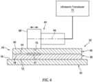
FIG. 6 is a partial schematic sectional illustration of a system for ultrasonic welding an arrangement of thermoplastic components together. -
FIG. 7 is a partial schematic sectional illustration of the system for ultrasonic welding another arrangement of thermoplastic components together. -
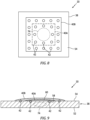
FIG. 8 is a partial schematic illustration of a repaired thermoplastic component. -
FIG. 9 is a partial schematic sectional illustration of the repaired thermoplastic component ofFIG. 8 . -
FIG. 10 is a partial schematic illustration of another repaired thermoplastic component. -
FIG. 11 is a partial schematic sectional illustration of the repaired thermoplastic component ofFIG. 10 . - The present disclosure includes methods for repairing (e.g., fixing, remanufacturing, etc.) a thermoplastic component 20 (e.g., a thermoplastic composite component) of an aerospace vehicle such as an aircraft, where an exemplary section of the
aircraft component 20 following its repair is shown inFIG. 1 . The aircraft may be an airplane, a helicopter, a drone (e.g., an unmanned aerial vehicle (UAV)) or any other manned or unmanned aerial vehicle or system. The present disclosure, however, is not limited to aircraft applications. The aerospace vehicle, for example, may alternatively be a space shuttle, a missile or a rocket. However, for ease of description, the aerospace vehicle is generally described as the aircraft below. - Referring to
FIG. 2 , theaircraft component 20 may be configured as or otherwise included as part of anacelle 22 of apropulsion system 24 for the aircraft. Theaircraft component 20, for example, may be (or may be part of) a component of anacelle inlet structure 26; e.g., a nacelle inlet lip (e.g., a nose lip), a nacelle outer barrel, a nacelle inner barrel, etc. In another example, theaircraft component 20 may be (or may be part of) another component of thepropulsion system nacelle 22 such as a cowl 28 (e.g., a fan cowl), or the like. Referring toFIG. 3 , theaircraft component 20 may alternatively be configured as or otherwise included as part of anairframe 30 of the aircraft. Theaircraft component 20, for example, may be (or may be part of) anaircraft wing 32, anaircraft fuselage skin 34, anaircraft stabilizer 36, or the like. Theaircraft component 20 may still alternatively be configured as or otherwise included as part of a structure within theaircraft airframe 30; e.g., within a cabin of the aircraft. The present disclosure, however, is not limited to manufacturing the foregoing exemplary aircraft components. Moreover, it is contemplated the methods of the present disclosure may be utilized for repairing non-aircraft components. However, for ease of description, the thermoplastic component is generally described below as theaircraft component 20. - The
aircraft component 20 ofFIG. 1 includes athermoplastic component base 38 and at least (or only) onethermoplastic component patch 40 ultrasonic welded to thecomponent base 38 at one ormore weld locations 42. Briefly, thecomponent base 38 is configured as a portion or an entirety of a damaged aircraft component which is to be repaired. Referring toFIG. 4 , each of thethermoplastic bodies thermoplastic matrix 44 and fiber-reinforcement 46 embedded within thethermoplastic matrix 44. - Examples of the
thermoplastic matrix 44 include, but are not limited to, a semicrystalline thermoplastic resin and an amorphous thermoplastic resin. Examples of the semicrystalline thermoplastic resin include polyester polyoxymethylene (POM), polyamide (PA), polyarylene sulfide, polyketone (PK), polyetherketone (PEK), polyether ether ketone (PEEK), polyether ketone ketone (PEKK), polyvinylidene fluoride (PVDF), polytetrafluoroethylene (PTFE), polyaryletherketone (PAEK), polyether nitrile (PEN), and liquid crystal polymer (LCP). Examples of the polyester include polytrimethylene terphthalate (PTT), polyethylene naphthalate (PEN), and liquid crystal polyester. An example of the polyarylene sulfide is polyphenylene sulfide (PPS). Examples of the amorphous thermoplastic resin include polycarbonate (PC), polymethyl methacrylate (PMMA), polyphenylene ether (PPE), polyimide (PI), polyamide imide (PAI), polyetherimide (PEI), polysulfone (PSU), polyether sulfone (PES), and polyarylate (PAR). The present disclosure, however, is not limited to the foregoing exemplary thermoplastic matrix materials. - The fiber-
reinforcement 46 may be arranged in one ormore layers 48 within the respectivethermoplastic body thermoplastic matrix 44. Eachlayer 48 of the fiber-reinforcement 46 may include a plurality of fiber-reinforcement fibers such as metal fibers, carbon fibers, insulating fibers, organic fibers, and inorganic fibers. Examples of the metal fibers include aluminum fibers, brass fibers, and stainless steel fibers. Examples of the carbon fibers include graphite fibers such as polyacrylonitrile (PAN)-based carbon fibers, rayon-based carbon fibers, lignin-based carbon fibers, and pitch-based carbon fibers. An example of the insulating fibers is glass fibers; e.g., fiberglass fibers. Examples of the organic fibers include aramid fibers, polyparaphenylene benzoxazole (PBO) fibers, polyphenylene sulfide fibers, polyester fibers, acrylic fibers, nylon fibers, and polyethylene fibers. Examples of the inorganic fibers include silicon carbide fibers and silicon nitride fibers. The present disclosure, however, is not limited to the foregoing exemplary fiber-reinforcement materials. - The fiber-
reinforcement 46 in eachlayer 48 of the respectivethermoplastic body reinforcement 46 in one or more or all of thelayers 48 may include multiple different fiber-reinforcement materials within thesame layer 48.Different layers 48 within the respectivethermoplastic body layers 48; e.g., onelayer 48 may include a first material or combination of materials and anotherlayer 48 may include a second material or combination of materials. Some or all of the fibers within arespective layer 48 may be continuous fibers. Some or all of the fibers within arespective layer 48 may also or alternatively be chopped fibers. Some or all of the fibers within arespective layer 48 may be unidirectional. Some or all of the fibers within arespective layer 48 may alternatively be multi-directional; e.g., in a woven sheet, a mat of chopped fibers, etc. The present disclosure, however, is not limited to the foregoing exemplary fiber types and/or fiber arrangements. Moreover, while eachthermoplastic body reinforcement 46, it is contemplated one or more of thesethermoplastic bodies reinforcement 46 embedded within thethermoplastic matrix 44. - In some embodiments, the
thermoplastic bodies thermoplastic bodies thermoplastic bodies -
FIG. 5 is a flow diagram of amethod 500 for repairing a thermoplastic component; e.g., a thermoplastic composite component. For ease of description, therepair method 500 is described below with reference to theaircraft component 20 ofFIG. 1 . The present disclosure, however, is not limited to repairing or otherwise welding such an exemplary component. - In
step 502, thecomponent base 38 is provided. The damaged component to be repaired, for example, may be removed from the aircraft and/or otherwise received and prepared for patching. Alternatively, the damaged component to be repaired may be prepared for patching while still installed with the aircraft. - In
step 504, thecomponent patch 40 is provided. A piece of thermoplastic stock material, for example, may be cutout to form thecomponent patch 40. The thermoplastic stock material may be a (e.g., laminated) sheet of thermoplastic composite material, prepreg material, etc. Thecomponent patch 40, of course, may alternatively be laminated, molded, pressed, injection molded, stamped and/or otherwise formed. - In
step 506, thecomponent base 38 may be arranged with arigid support structure 50; e.g., a metal anvil or die. For example, referring toFIG. 6 , thecomponent base 38 may be disposed on thesupport structure 50. Thecomponent base 38 ofFIG. 6 has a thickness that extends vertically between and to a first (e.g., lower)surface 52 of thecomponent base 38 and a second (e.g., upper) surface 54 of thecomponent base 38. The basefirst surface 52 ofFIG. 6 is abutted against and contacts a (e.g., upper)support surface 56 of thesupport structure 50. The basefirst surface 52, for example, may lay against (e.g., rest on, be disposed in full contact with, be disposed flat against, etc.) thestructure support surface 56. While thesurfaces FIG. 6 , it is contemplated thesurfaces FIG. 6 . Moreover, thesurfaces FIG. 6 . For example, thesurfaces FIG. 6 , thecomponent base 38 may be (e.g., temporarily) secured to thesupport structure 50, or thecomponent base 38 may simply rest against thesupport structure 50. - In
step 508, thecomponent patch 40 is arranged with thecomponent base 38 for the ultrasonic welding. For example, thecomponent patch 40 ofFIG. 6 is disposed on thecomponent base 38. Thecomponent patch 40 ofFIG. 6 has a thickness that extends vertically between and to a first (e.g., lower)surface 58 of thecomponent patch 40 and a second (e.g., upper) surface 60 of thecomponent patch 40. The patchfirst surface 58 ofFIG. 6 is abutted against and contacts the basesecond surface 54. The patchfirst surface 58, for example, may lay against (e.g., rest on, be disposed in full contact with, be disposed flat against, etc.) the basesecond surface 54. While thesurfaces FIG. 6 , it is contemplated thesurfaces FIG. 6 . Moreover, thesurfaces FIG. 6 . For example, thesurfaces FIG. 6 , thecomponent base 38 is disposed vertically between and contacts thesupport structure 50 and thecomponent patch 40; e.g., without any vertical gaps and/or other materials (e.g., adhesive, etc.) in between. Here, the (still discrete, non-welded)thermoplastic bodies stack 62 on / over thesupport structure 50. Thecomponent patch 40 may be (e.g., temporarily) secured to thecomponent base 38, or thecomponent patch 40 may simply rest against thecomponent base 38. - In
step 510, an ultrasonic horn 64 (e.g., a sonotrode) used for the ultrasonic welding is arranged with thecomponent patch 40. Theultrasonic horn 64 extends longitudinally along acenterline 66 of theultrasonic horn 64 to adistal end 68 of theultrasonic horn 64. Thisultrasonic horn 64 includes anengagement surface 70 at (e.g., on, adjacent or proximate) the horndistal end 68. Thisengagement surface 70 is disposed to a face of the ultrasonic horn 64 (e.g., to a side of the ultrasonic horn 64), and extends longitudinally along thehorn centerline 66. Theengagement surface 70 is positioned over thecomponent patch 40, and engages (e.g., fully contacts) thecomponent patch 40 and its patchsecond surface 60. With this arrangement, theultrasonic horn 64 extends longitudinally along thecomponent patch 40 and its patchsecond surface 60. Thehorn centerline 66, for example, may be substantially (e.g., within 2-5 degrees of) or completely parallel with thecomponent patch 40 and its patchsecond surface 60. Theultrasonic horn 64 ofFIG. 6 is further operatively coupled to anultrasonic transducer 72. - In
step 512, thethermoplastic bodies ultrasonic horn 64. Theultrasonic transducer 72, for example, is configured to move (e.g., translate, oscillate, etc.) theultrasonic horn 64 back-and-forth longitudinally along thehorn centerline 66 during the ultrasonic welding. This movement of theultrasonic horn 64 heats the thermoplastic matrix 44 (seeFIG. 4 ) of thecomponent patch 40 and thecomponent base 38. The heating softens and then locally melts thethermoplastic matrix 44 and thereby (e.g., spot) welds thecomponent patch 40 to thecomponent base 38 at and about a point longitudinally aligned with theultrasonic horn 64 and itsengagement surface 70; e.g., theweld location 42. - In
step 514, at least (or only) thewelding step 512 may be repeated one or more times at different locations along the thermoplasticcomposite body stack 62 and itscomponent patch 40 to weld thecomponent patch 40 to thecomponent base 38 at one or more additional locations. Thecomponent patch 40 may thereby be spot welded to thecomponent base 38 to (e.g., fully) connect thethermoplastic bodies aircraft component 20. Of course, it is contemplated theultrasonic horn 64 may alternatively translated to provide a (e.g., continuous) weld seam between thecomponent patch 40 and thecomponent base 38. By ultrasonic welding thethermoplastic bodies thermoplastic bodies - While the
aircraft component 20 ofFIG. 6 includes thesingle component patch 40, it is contemplated theaircraft component 20 may alternatively includemultiple component patches 40A-C (generally referred to as "40") as shown inFIG. 7 ; e.g., a multi-layered patch / patch structure. For example, the secondthermoplastic component patch 40B ("second component patch") may be ultrasonic welded to thefirst component patch 40A, for example, following the ultrasonic welding of thefirst component patch 40A to thecomponent base 38. The thirdthermoplastic component patch 40C ("third component patch") may be ultrasonic welded to thesecond component patch 40B, for example, following the ultrasonic welding of thesecond component patch 40B to thefirst component patch 40A. The welding of theseadditional component patches - Referring to
FIGS. 8 and 9 , the one ormore component patches 40 may be configured to cover a damagedportion 74 of thecomponent base 38. Thefirst component patch 40A ofFIG. 9 , for example, contacts the base second surface 54 (e.g., an exterior surface of the component base 38) and extends over the damagedportion 74 of thecomponent base 38. Thisfirst component patch 40A is horizontal ultrasonic welded to thecomponent base 38. Thesecond component patch 40B ofFIG. 9 contacts thefirst component patch 40A and may also contact the basesecond surface 54. Thissecond component patch 40B is horizontal ultrasonic welded to thefirst component patch 40A and/or horizontal ultrasonic welded to thecomponent base 38. - Referring to
FIGS. 10 and 11 , the one ormore component patches 40 may alternatively be configured to at least partially or completely replace the damaged portion of thecomponent base 38. For example, some or all of the damaged portion of thecomponent base 38 may be removed from thecomponent base 38 via one or more removal techniques; e.g., machining, milling, cutting, grit blasting, etc. Referring toFIG. 11 , this removal may form an aperture 75 (e.g., a tapered aperture, a plateaued aperture, etc.) in thecomponent base 38. Theaperture 75 ofFIG. 11 projects (e.g., partially) vertically into thecomponent base 38 from its base second surface 54 (e.g., an exterior surface of the component base 38) to one or moreinterior surfaces component base 38. Following this removal, one or more thecomponent patches 40 may be individually disposed in / over theaperture 75 and welded to thecomponent base 38. Thefirst component patch 40A ofFIG. 11 contacts the innermostinterior surface 76A. Thefirst component patch 40A is horizontal ultrasonic welded to thecomponent base 38. Thesecond component patch 40B ofFIG. 11 contacts thefirst component patch 40A and may also contact the next outwardinterior surface 76B. Thesecond component patch 40B is horizontal ultrasonic welded to thefirst component patch 40A and/or horizontal ultrasonic welded to thecomponent base 38. Thethird component patch 40C ofFIG. 11 is disposed outside of theaperture 75. Thethird component patch 40C contacts thesecond component patch 40B and may also contact the basesecond surface 54. Thethird component patch 40C is horizontal ultrasonic welded to thesecond component patch 40B and/or horizontal ultrasonic welded to thecomponent base 38. - In some embodiments, referring to
FIGS. 9 and11 , the base second surface 54 (along with the exposed component patch) may at least partially or completely form an exterior surface of theaircraft component 20. This exterior surface may also be an aerodynamic flow surface of theaircraft component 20. In other embodiments, referring toFIG. 6 , the basefirst surface 52 may at least partially or completely form an exterior surface of theaircraft component 20. This exterior surface may also be an aerodynamic flow surface of theaircraft component 20. Note, by arranging the aerodynamic flow surface against thesupport structure 50, a shape and contour of the aerodynamic flow surface may be preserved during the horizontal ultrasonic welding. - The foregoing methods utilize localized heating at the weld interface. This localized heating may have less impact on nearby components and structure. Therefore, the methods of the present disclosure may be performed without, for example, a heating blanket. Moreover, the methods of the present disclosure may be performed quickly; e.g., less than thirty minutes depending upon the specific task; e.g., repair.
- While various embodiments of the present invention have been disclosed, it will be apparent to those of ordinary skill in the art that many more embodiments and implementations are possible within the scope of the invention. For example, the present invention as described herein includes several aspects and embodiments that include particular features. Although these features may be described individually, it is within the scope of the present invention that some or all of these features may be combined with any one of the aspects and remain within the scope of the invention. Accordingly, the present invention is not to be restricted except in light of the attached claims and their equivalents.
Claims (15)
- A repair method, comprising:arranging a thermoplastic patch (40) on a thermoplastic aerospace component (20), the thermoplastic patch (40) contacting the thermoplastic aerospace component (20); andhorizontal ultrasonic welding the thermoplastic patch (40) to the thermoplastic aerospace component (20) using an ultrasonic horn (64).
- The repair method of claim 1, wherein:the ultrasonic horn (64) extends along a centerline (66);a face (70) of the ultrasonic horn (64) extends longitudinally along the centerline (66) and engages the thermoplastic patch (40); andthe ultrasonic horn (64) moves back and forth along the centerline (66) during the horizontal ultrasonic welding, optionally wherein:the face (70) of the ultrasonic horn (64) contacts a surface (60) of the thermoplastic patch (40); andthe centerline (66) is parallel to the surface of the thermoplastic patch (40).
- The repair method of claim 1 or 2, wherein:the thermoplastic patch (40) has a surface (58) that extends between opposing exterior sides of the thermoplastic patch (40); andan entirety of the surface (58) contacts the thermoplastic aerospace component (20).
- The repair method of any preceding claim, wherein the thermoplastic patch (40):is connected to the thermoplastic aerospace component (20) without use of an adhesive and/or without use of thermoplastic film as an energy director; and/orincludes a thermoplastic matrix (44) and fiber-reinforcement (46) embedded within the thermoplastic matrix (44).
- The repair method of any preceding claim, wherein the thermoplastic aerospace component (20) includes a thermoplastic matrix (44) and fiber-reinforcement (46) embedded within the thermoplastic matrix (44).
- The repair method of any preceding claim, whereinthe thermoplastic aerospace component (20) includes an aperture (75), an exterior surface (54) and an interior surface (76A, 76B);the aperture (75) extends into the thermoplastic aerospace component (20) from the exterior surface (54) to the interior surface (76A, 76B); andthe thermoplastic patch (40) is disposed in the aperture (75) and contacts the interior surface (76A, 76B).
- The repair method of any preceding claim, further comprising:arranging a second thermoplastic patch (40B) in the aperture (75), the second thermoplastic patch (40B) contacting a surface of the thermoplastic patch (40A); andhorizontal ultrasonic welding the second thermoplastic patch (40B) to the thermoplastic patch (40A) using the ultrasonic horn (64), optionally further comprising:horizontal ultrasonic welding the second thermoplastic patch (40B) to the thermoplastic aerospace component (20) using the ultrasonic horn (64);the second thermoplastic patch (40B) contacting a second interior surface of the thermoplastic aerospace component (20).
- The repair method of any preceding claim, further comprising:arranging a or the second thermoplastic patch (40B) on the exterior surface (54), the second thermoplastic patch (40B) covering the aperture (75); andhorizontal ultrasonic welding the second thermoplastic patch (40B) to the thermoplastic aerospace component (20) using the ultrasonic horn (64).
- The repair method of any preceding claim, further comprising removing a damaged portion (74) of the thermoplastic aerospace component (20) to form a or the aperture (75).
- The repair method of any preceding claim, wherein the thermoplastic patch (40) covers a damaged portion (74) of the thermoplastic aerospace component (20).
- The repair method of any preceding claim, wherein the thermoplastic patch (40) is horizontal ultrasonic welded to the thermoplastic aerospace component (20):at a plurality of spot weld locations along the thermoplastic patch (40); and/oralong an elongated weld seam.
- A method, comprising:removing material from a first thermoplastic body (38) to form an aperture (75) in the first thermoplastic body (38), the aperture (75) extending into the first thermoplastic body (38) from an exterior surface (54) of the first thermoplastic body (38) to an interior surface (76A, 76B) of the first thermoplastic body (38);arranging a second thermoplastic body (40A) in the aperture (75), the second thermoplastic body (40A) contacting the interior surface (76A, 76B) of the first thermoplastic body (38); andultrasonic welding the second thermoplastic body (40A) to the first thermoplastic body (38) using an ultrasonic horn (64), the ultrasonic horn (64) engaging a surface (60) of the second thermoplastic body (40A), and the ultrasonic horn (64) moving back-and-forth along the surface (60) of the second thermoplastic body (40A) during the ultrasonic welding of the second thermoplastic body (40A), optionally further comprising:arranging a third thermoplastic body (40B) in the aperture (75), the third thermoplastic body contacting the surface (60) of the second thermoplastic body (40A); andultrasonic welding the third thermoplastic body (40B) to the second thermoplastic body (40A) using the ultrasonic horn (64), the ultrasonic horn (64) engaging a surface of the third thermoplastic body (40B), and the ultrasonic horn (64) moving back-and-forth along the surface of the third thermoplastic body (40B) during the ultrasonic welding of the third thermoplastic body (40B).
- The method of claim 12, further comprising:arranging a or the third thermoplastic body (40B) in the aperture (75), the third thermoplastic body (40B) contacting a second interior surface (76A, 76B) of the first thermoplastic body (38); andultrasonic welding the third thermoplastic body (40B) to the first thermoplastic body (38) using the ultrasonic horn (64), the ultrasonic horn (64) engaging a surface of the third thermoplastic body (40B), and the ultrasonic horn (64) moving back-and-forth along the surface of the third thermoplastic body (40B) during the ultrasonic welding of the third thermoplastic body (40B).
- The method of claim 12 or 13, further comprising:arranging a or the third thermoplastic body (40B) on the exterior surface (54) of the first thermoplastic body (38), the third thermoplastic body (40B) covering the aperture (75); andultrasonic welding the third thermoplastic body (40B) to the first thermoplastic body (38) using the ultrasonic horn (64), the ultrasonic horn (64) engaging a surface of the third thermoplastic body (40B), and the ultrasonic horn (64) moving back-and-forth along the surface of the third thermoplastic body (40B) during the ultrasonic welding of the third thermoplastic body (40B).
- A method, comprising:providing a first thermoplastic body (38) with a damaged portion (74);arranging a second thermoplastic body (40) on an exterior surface (54) of the first thermoplastic body (38), the second thermoplastic body (40) covering the first thermoplastic body (38); andultrasonic welding the second thermoplastic body (40) to the first thermoplastic body (38) using an ultrasonic horn (64), the ultrasonic horn (64) engaging a surface of the second thermoplastic body (40), and the ultrasonic horn (64) moving back-and-forth along the surface of the second thermoplastic body (40) during the ultrasonic welding of the second thermoplastic body (40).
Applications Claiming Priority (1)
| Application Number | Priority Date | Filing Date | Title |
|---|---|---|---|
| US18/227,691 US20250033302A1 (en) | 2023-07-28 | 2023-07-28 | Horizontal ultrasonic welding thermoplastic material |
Publications (1)
| Publication Number | Publication Date |
|---|---|
| EP4497578A1 true EP4497578A1 (en) | 2025-01-29 |
Family
ID=92106929
Family Applications (1)
| Application Number | Title | Priority Date | Filing Date |
|---|---|---|---|
| EP24191291.4A Pending EP4497578A1 (en) | 2023-07-28 | 2024-07-26 | Horizontal ultrasonic welding thermoplastic material |
Country Status (2)
| Country | Link |
|---|---|
| US (1) | US20250033302A1 (en) |
| EP (1) | EP4497578A1 (en) |
Citations (2)
| Publication number | Priority date | Publication date | Assignee | Title |
|---|---|---|---|---|
| CA2442522A1 (en) * | 2003-09-26 | 2005-03-26 | Dawn E. Cammack | Method and apparatus for repairing synthetic textiles |
| US10625475B2 (en) * | 2016-12-27 | 2020-04-21 | Envision Aesc Japan Ltd. | Ultrasonic bonding tool and ultrasonic bonding method |
Family Cites Families (1)
| Publication number | Priority date | Publication date | Assignee | Title |
|---|---|---|---|---|
| US20170355149A1 (en) * | 2016-06-08 | 2017-12-14 | GM Global Technology Operations LLC | Inspection and repair of adhesive-bonded joint using ultrasonic pulses |
-
2023
- 2023-07-28 US US18/227,691 patent/US20250033302A1/en active Pending
-
2024
- 2024-07-26 EP EP24191291.4A patent/EP4497578A1/en active Pending
Patent Citations (2)
| Publication number | Priority date | Publication date | Assignee | Title |
|---|---|---|---|---|
| CA2442522A1 (en) * | 2003-09-26 | 2005-03-26 | Dawn E. Cammack | Method and apparatus for repairing synthetic textiles |
| US10625475B2 (en) * | 2016-12-27 | 2020-04-21 | Envision Aesc Japan Ltd. | Ultrasonic bonding tool and ultrasonic bonding method |
Also Published As
| Publication number | Publication date |
|---|---|
| US20250033302A1 (en) | 2025-01-30 |
Similar Documents
| Publication | Publication Date | Title |
|---|---|---|
| US10220935B2 (en) | Open-channel stiffener | |
| KR102412502B1 (en) | Wing and method of manufacturing | |
| US9302759B2 (en) | Flexible truss frame and method of making the same | |
| US11455979B2 (en) | Structural single degree of freedom face sheet acoustic liner | |
| JP6272202B2 (en) | Bending part in composite panel | |
| US10232926B2 (en) | Integrated lamination process for manufacturing a shell element | |
| US10005267B1 (en) | Formation of complex composite structures using laminate templates | |
| EP3584066A1 (en) | Method of making a laminate | |
| EP4585405A1 (en) | Delamination and edge damage repair on thermoplastic composites | |
| EP3747637B1 (en) | Method to integrate a first part and a second part comprising composite material | |
| US20170028698A1 (en) | Method for joining thermoset components | |
| US10870265B2 (en) | Method for limiting interlaminar fatigue in composite laminate and a component incorporating the same | |
| US9630376B2 (en) | Composite filler | |
| US20250033302A1 (en) | Horizontal ultrasonic welding thermoplastic material | |
| EP4467322A1 (en) | Ultrasonic welding thermoplastic material using energy transmission material | |
| US20250312981A1 (en) | Continuous ultrasonic welding thermoplastic material for aerospace component repair | |
| CN110539493A (en) | Component comprising a sub-element of a fibre-composite material, and method and device for connecting sub-elements | |
| US12351305B2 (en) | Thermoplastic composite structure and methods for forming | |
| EP4209334B1 (en) | Vibration welding system and method | |
| EP4215344B1 (en) | Vibration welding fiber-reinforced composite aircraft structures | |
| US20260014762A1 (en) | Repairing composite thermoplastic component using induction / conductive heating | |
| US20250367892A1 (en) | Forming aircraft component with lightning strike protection | |
| US20250042578A1 (en) | Consolidating thermoplastic material with induction heating coil and heating plate(s) | |
| EP3623152A1 (en) | Component with bonded thermoplastic and thermoset layers | |
| EP4474140A1 (en) | Structural component, method for manufacturing a structural component and aircraft |
Legal Events
| Date | Code | Title | Description |
|---|---|---|---|
| PUAI | Public reference made under article 153(3) epc to a published international application that has entered the european phase |
Free format text: ORIGINAL CODE: 0009012 |
|
| STAA | Information on the status of an ep patent application or granted ep patent |
Free format text: STATUS: THE APPLICATION HAS BEEN PUBLISHED |
|
| AK | Designated contracting states |
Kind code of ref document: A1 Designated state(s): AL AT BE BG CH CY CZ DE DK EE ES FI FR GB GR HR HU IE IS IT LI LT LU LV MC ME MK MT NL NO PL PT RO RS SE SI SK SM TR |
|
| STAA | Information on the status of an ep patent application or granted ep patent |
Free format text: STATUS: REQUEST FOR EXAMINATION WAS MADE |
|
| 17P | Request for examination filed |
Effective date: 20250729 |
|
| RIC1 | Information provided on ipc code assigned before grant |
Ipc: B29C 65/08 20060101AFI20260331BHEP Ipc: B29C 73/10 20060101ALI20260331BHEP Ipc: B29C 73/34 20060101ALI20260331BHEP Ipc: B29C 73/04 20060101ALI20260331BHEP Ipc: B29C 73/06 20060101ALI20260331BHEP Ipc: B29L 31/30 20060101ALN20260331BHEP |
|
| GRAP | Despatch of communication of intention to grant a patent |
Free format text: ORIGINAL CODE: EPIDOSNIGR1 |
|
| STAA | Information on the status of an ep patent application or granted ep patent |
Free format text: STATUS: GRANT OF PATENT IS INTENDED |
|
| RIC1 | Information provided on ipc code assigned before grant |
Ipc: B29C 65/08 20060101AFI20260407BHEP Ipc: B29C 73/10 20060101ALI20260407BHEP Ipc: B29C 73/34 20060101ALI20260407BHEP Ipc: B29C 73/04 20060101ALI20260407BHEP Ipc: B29C 73/06 20060101ALI20260407BHEP Ipc: B29L 31/30 20060101ALN20260407BHEP |