EP4497574A1 - 3-d lattice reinforced composite with strain limiter - Google Patents
3-d lattice reinforced composite with strain limiter Download PDFInfo
- Publication number
- EP4497574A1 EP4497574A1 EP24191258.3A EP24191258A EP4497574A1 EP 4497574 A1 EP4497574 A1 EP 4497574A1 EP 24191258 A EP24191258 A EP 24191258A EP 4497574 A1 EP4497574 A1 EP 4497574A1
- Authority
- EP
- European Patent Office
- Prior art keywords
- lattice
- matrix phase
- struts
- composite
- structures
- Prior art date
- Legal status (The legal status is an assumption and is not a legal conclusion. Google has not performed a legal analysis and makes no representation as to the accuracy of the status listed.)
- Pending
Links
Images




Classifications
-
- B—PERFORMING OPERATIONS; TRANSPORTING
- B33—ADDITIVE MANUFACTURING TECHNOLOGY
- B33Y—ADDITIVE MANUFACTURING, i.e. MANUFACTURING OF THREE-DIMENSIONAL [3D] OBJECTS BY ADDITIVE DEPOSITION, ADDITIVE AGGLOMERATION OR ADDITIVE LAYERING, e.g. BY 3D PRINTING, STEREOLITHOGRAPHY OR SELECTIVE LASER SINTERING
- B33Y70/00—Materials specially adapted for additive manufacturing
- B33Y70/10—Composites of different types of material, e.g. mixtures of ceramics and polymers or mixtures of metals and biomaterials
-
- B—PERFORMING OPERATIONS; TRANSPORTING
- B29—WORKING OF PLASTICS; WORKING OF SUBSTANCES IN A PLASTIC STATE IN GENERAL
- B29C—SHAPING OR JOINING OF PLASTICS; SHAPING OF MATERIAL IN A PLASTIC STATE, NOT OTHERWISE PROVIDED FOR; AFTER-TREATMENT OF THE SHAPED PRODUCTS, e.g. REPAIRING
- B29C64/00—Additive manufacturing, i.e. manufacturing of three-dimensional [3D] objects by additive deposition, additive agglomeration or additive layering, e.g. by 3D printing, stereolithography or selective laser sintering
- B29C64/10—Processes of additive manufacturing
- B29C64/171—Processes of additive manufacturing specially adapted for manufacturing multiple 3D objects
-
- B—PERFORMING OPERATIONS; TRANSPORTING
- B22—CASTING; POWDER METALLURGY
- B22F—WORKING METALLIC POWDER; MANUFACTURE OF ARTICLES FROM METALLIC POWDER; MAKING METALLIC POWDER; APPARATUS OR DEVICES SPECIALLY ADAPTED FOR METALLIC POWDER
- B22F3/00—Manufacture of workpieces or articles from metallic powder characterised by the manner of compacting or sintering; Apparatus specially adapted therefor ; Presses and furnaces
- B22F3/10—Sintering only
- B22F3/11—Making porous workpieces or articles
- B22F3/1103—Making porous workpieces or articles with particular physical characteristics
- B22F3/1115—Making porous workpieces or articles with particular physical characteristics comprising complex forms, e.g. honeycombs
-
- B—PERFORMING OPERATIONS; TRANSPORTING
- B22—CASTING; POWDER METALLURGY
- B22F—WORKING METALLIC POWDER; MANUFACTURE OF ARTICLES FROM METALLIC POWDER; MAKING METALLIC POWDER; APPARATUS OR DEVICES SPECIALLY ADAPTED FOR METALLIC POWDER
- B22F3/00—Manufacture of workpieces or articles from metallic powder characterised by the manner of compacting or sintering; Apparatus specially adapted therefor ; Presses and furnaces
- B22F3/10—Sintering only
- B22F3/11—Making porous workpieces or articles
- B22F3/1103—Making porous workpieces or articles with particular physical characteristics
- B22F3/1118—Making porous workpieces or articles with particular physical characteristics comprising internal reinforcements
-
- B—PERFORMING OPERATIONS; TRANSPORTING
- B22—CASTING; POWDER METALLURGY
- B22F—WORKING METALLIC POWDER; MANUFACTURE OF ARTICLES FROM METALLIC POWDER; MAKING METALLIC POWDER; APPARATUS OR DEVICES SPECIALLY ADAPTED FOR METALLIC POWDER
- B22F5/00—Manufacture of workpieces or articles from metallic powder characterised by the special shape of the product
- B22F5/10—Manufacture of workpieces or articles from metallic powder characterised by the special shape of the product of articles with cavities or holes, not otherwise provided for in the preceding subgroups
-
- B—PERFORMING OPERATIONS; TRANSPORTING
- B22—CASTING; POWDER METALLURGY
- B22F—WORKING METALLIC POWDER; MANUFACTURE OF ARTICLES FROM METALLIC POWDER; MAKING METALLIC POWDER; APPARATUS OR DEVICES SPECIALLY ADAPTED FOR METALLIC POWDER
- B22F7/00—Manufacture of composite layers, workpieces, or articles, comprising metallic powder, by sintering the powder, with or without compacting wherein at least one part is obtained by sintering or compression
- B22F7/002—Manufacture of composite layers, workpieces, or articles, comprising metallic powder, by sintering the powder, with or without compacting wherein at least one part is obtained by sintering or compression of porous nature
-
- B—PERFORMING OPERATIONS; TRANSPORTING
- B22—CASTING; POWDER METALLURGY
- B22F—WORKING METALLIC POWDER; MANUFACTURE OF ARTICLES FROM METALLIC POWDER; MAKING METALLIC POWDER; APPARATUS OR DEVICES SPECIALLY ADAPTED FOR METALLIC POWDER
- B22F7/00—Manufacture of composite layers, workpieces, or articles, comprising metallic powder, by sintering the powder, with or without compacting wherein at least one part is obtained by sintering or compression
- B22F7/06—Manufacture of composite layers, workpieces, or articles, comprising metallic powder, by sintering the powder, with or without compacting wherein at least one part is obtained by sintering or compression of composite workpieces or articles from parts, e.g. to form tipped tools
-
- B—PERFORMING OPERATIONS; TRANSPORTING
- B29—WORKING OF PLASTICS; WORKING OF SUBSTANCES IN A PLASTIC STATE IN GENERAL
- B29C—SHAPING OR JOINING OF PLASTICS; SHAPING OF MATERIAL IN A PLASTIC STATE, NOT OTHERWISE PROVIDED FOR; AFTER-TREATMENT OF THE SHAPED PRODUCTS, e.g. REPAIRING
- B29C64/00—Additive manufacturing, i.e. manufacturing of three-dimensional [3D] objects by additive deposition, additive agglomeration or additive layering, e.g. by 3D printing, stereolithography or selective laser sintering
- B29C64/30—Auxiliary operations or equipment
- B29C64/307—Handling of material to be used in additive manufacturing
- B29C64/321—Feeding
- B29C64/336—Feeding of two or more materials
-
- B—PERFORMING OPERATIONS; TRANSPORTING
- B33—ADDITIVE MANUFACTURING TECHNOLOGY
- B33Y—ADDITIVE MANUFACTURING, i.e. MANUFACTURING OF THREE-DIMENSIONAL [3D] OBJECTS BY ADDITIVE DEPOSITION, ADDITIVE AGGLOMERATION OR ADDITIVE LAYERING, e.g. BY 3D PRINTING, STEREOLITHOGRAPHY OR SELECTIVE LASER SINTERING
- B33Y10/00—Processes of additive manufacturing
-
- B—PERFORMING OPERATIONS; TRANSPORTING
- B33—ADDITIVE MANUFACTURING TECHNOLOGY
- B33Y—ADDITIVE MANUFACTURING, i.e. MANUFACTURING OF THREE-DIMENSIONAL [3D] OBJECTS BY ADDITIVE DEPOSITION, ADDITIVE AGGLOMERATION OR ADDITIVE LAYERING, e.g. BY 3D PRINTING, STEREOLITHOGRAPHY OR SELECTIVE LASER SINTERING
- B33Y70/00—Materials specially adapted for additive manufacturing
-
- B—PERFORMING OPERATIONS; TRANSPORTING
- B33—ADDITIVE MANUFACTURING TECHNOLOGY
- B33Y—ADDITIVE MANUFACTURING, i.e. MANUFACTURING OF THREE-DIMENSIONAL [3D] OBJECTS BY ADDITIVE DEPOSITION, ADDITIVE AGGLOMERATION OR ADDITIVE LAYERING, e.g. BY 3D PRINTING, STEREOLITHOGRAPHY OR SELECTIVE LASER SINTERING
- B33Y80/00—Products made by additive manufacturing
-
- B—PERFORMING OPERATIONS; TRANSPORTING
- B22—CASTING; POWDER METALLURGY
- B22F—WORKING METALLIC POWDER; MANUFACTURE OF ARTICLES FROM METALLIC POWDER; MAKING METALLIC POWDER; APPARATUS OR DEVICES SPECIALLY ADAPTED FOR METALLIC POWDER
- B22F10/00—Additive manufacturing of workpieces or articles from metallic powder
- B22F10/20—Direct sintering or melting
- B22F10/28—Powder bed fusion, e.g. selective laser melting [SLM] or electron beam melting [EBM]
-
- B—PERFORMING OPERATIONS; TRANSPORTING
- B29—WORKING OF PLASTICS; WORKING OF SUBSTANCES IN A PLASTIC STATE IN GENERAL
- B29K—INDEXING SCHEME ASSOCIATED WITH SUBCLASSES B29B, B29C OR B29D, RELATING TO MOULDING MATERIALS OR TO MATERIALS FOR MOULDS, REINFORCEMENTS, FILLERS OR PREFORMED PARTS, e.g. INSERTS
- B29K2995/00—Properties of moulding materials, reinforcements, fillers, preformed parts or moulds
- B29K2995/0012—Properties of moulding materials, reinforcements, fillers, preformed parts or moulds having particular thermal properties
- B29K2995/0016—Non-flammable or resistant to heat
Definitions
- the present disclosure relates generally to composite structures and, more particularly, to three-dimensional (3-D) lattice reinforced composite structures.
- Aircraft structures such as engine and fuselage structures, face multiple challenges such as retaining sufficient stiffness to function effectively as structural components while addressing the three dimensional stresses that result from the aircraft maneuvering while in flight. Additionally, it is desirable for such structures to be light weight for fuel efficiency and payload capability.
- such structures can made from metallic or polymeric foam cores sandwiched between thin sheets of facing materials to form load bearing structures that may include aerodynamic surfaces.
- the foam cores can be replaced by certain repeating 3-D lattice structures, which can be made from metallic or polymeric materials.
- One aspect of the invention includes a three-dimensional (3-D) composite structure having a 3-D lattice structure that includes a plurality of struts, a matrix phase surrounding the 3-D lattice structure, and a strain limiting structure positioned at or near a center of the 3-D lattice structure.
- Another aspect of the invention includes a method of making a three-dimensional (3-D) composite structure, including the steps of forming, using additive manufacturing techniques, a 3-D lattice structure having a plurality of struts, forming, using additive manufacturing techniques, a matrix phase surrounding the 3-D lattice structure, and forming, using additive manufacturing techniques, a strain limiting structure positioned at or near a center of the 3-D lattice structure.
- structures that can demonstrate a combination of light weight, high stiffness, strength, and toughness.
- such structures can made from metallic or polymeric foam cores sandwiched between thin sheets of facing materials to form load bearing structures that may include aerodynamic surfaces.
- the foam cores can be replaced by certain repeating three-dimensional (3-D) lattices structures, can be made from metallic or polymeric materials.
- Such structures are used as load bearing structures and, if desired, may include aerodynamic surfaces.
- Surrounding or filling the repeating 3-D lattice structures, which can be made from metallic or polymeric materials, with a lower modulus, higher toughness, polymeric material, polymer foam, or metallic foam creates a composite material with the polymeric material or foam as a matrix phase and the 3-D lattice structures as a reinforcing phase.
- Such a composite can be designed to have high strength and stiffness and to have a very high global Poisson's ratio ⁇ 1. When loaded in compression, contraction of the lattice elements around the tough matrix phase dissipates compressive forces and results in deformation with small strains. Such a composite will have high stiffness, high strength, and enhanced toughness.
- the performance of composite materials made from a repeating 3-D lattice structure having a polymeric material, polymeric foam, or metallic foam matrix phase can be enhanced by embedding a strain limiting structure into the matrix phase at or near the center of each 3-D lattice structure.
- the strain limiting structure which can have a higher strength than the matrix phase, limits deformation of struts that make up the 3-D lattice structure, resulting in an overall higher ultimate strength for the composite material.
- Figs. 1A and 1B show 3-D lattice structures that can be the basis for the repeating 3-D lattice structure used as the reinforcing phase in the composite materials of this disclosure.
- the repeating 3-D lattice structure can be formed from any polymeric or metallic material deemed appropriate for a particular application.
- the repeating 3-D lattice structure can be made from steel, aluminum, titanium and alloys, including but not limited to Inco 625.
- Fig. 1A shows a 3-D lattice structure 10 , in this case a stellated octahedron, formed with a plurality of struts 12 , including two sets of stiffening struts 13, 14 .
- the struts 12 , 13, 14 can be made from suitable metallic or polymeric materials and can be formed with additive manufacturing (AM) techniques known in the art.
- AM techniques can include powder bed fusion processes (e.g., laser powder bed fusion, electron beam powder bed fusion, etc.), direct ink writing, fused deposition modeling, material jetting, stereolithography, and other processes.
- powder bed fusion processes e.g., laser powder bed fusion, electron beam powder bed fusion, etc.
- direct ink writing e.g., fused deposition modeling, material jetting, stereolithography, and other processes.
- fused deposition modeling e.g., fused deposition modeling
- material jetting e.g., stereolithography
- the struts 12 , 13 , 14 are shown with constant diameter circular cross-sections, the cross-sections could also have any other suitable geometric shape (e.g., triangular, rectangular, pentangular, etc.) and may have varying cross-sectional dimensions.
- the combination of materials used to make the struts 12 , 13 , 14 and the shape and cross-sectional dimensions of the struts 12 , 13 , 14 can be selected to result in components having mechanical properties, including but not limited to modulus and toughness, deemed appropriate for a particular application.
- the spaces the struts 12 , 13 , 14 include open spaces 16 that can be filled with a suitable matrix phase 18 (see Fig.
- a polymeric material, a polymeric foam, or a metallic foam such as a polymeric material, a polymeric foam, or a metallic foam, to form a composite material.
- the polymeric material, a polymeric foam, or a metallic foam can be any such material useful as a matrix phase 18 for a particular application.
- the polymeric material, a polymeric foam, or a metallic foam matrix phase 18 may have a lower modulus and higher toughness than the material used to make the struts 12 , 13 , 14.
- the 3-D lattice structure 10 is shown as a stellated octahedron other 3-D geometric shapes formed with a lattice structure can be used as the reinforcing phase in the composite materials of this disclosure.
- Figs. 2A and 2B show a 3-D lattice structure 20 similar to that depicted in Fig. 1A with the reinforcing struts 14 removed.
- the resulting 3-D lattice structure 20 includes a plurality of struts 22 with a single set of stiffening struts 23. Removing the reinforcing struts 24 from the 3-D lattice structure 10 of Fig. 1A to form 3-D lattice structure 20 is an example of how the 3-D lattice structures of this disclosure can be "tuned" to absorb more energy. Similar to the 3-D lattice structure 10 of Fig. 1A , the 3-D lattice structure 20 of Fig.
- FIG. 2A include open spaces 26 that can be filled with a suitable matrix phase 28 (see Fig. 2B ), such as a polymeric material, a polymeric foam, or a metallic foam, to form a composite material.
- a suitable matrix phase 28 such as a polymeric material, a polymeric foam, or a metallic foam, to form a composite material.
- the struts 22 , 23 and the matrix 28 of Figs. 2A and 2B can be made from the same materials and have the same properties as discussed above with regard to the comparable elements of Figs. 1A and 1B and 2A/2B .
- the 3-D lattice structure 20 is shown as a stellated octahedron other 3-D geometric shapes formed with a lattice structure can be used as the reinforcing phase in the composite materials of this disclosure.
- Figs. 3A and 3B show a 3-D lattice structure 30 similar to that depicted in Fig. 2A that includes a strain limiting structure 39 positioned an open space 36 at or near the center of the 3-D lattice structure 30 such that strain limiting structure 39 will be embedded in the matrix phase 38 (see Fig. 3B ) when the 3-D lattice structure 30 in filled with the matrix phase 38.
- the struts 32 , 33 and the matrix 38 of Figs. 3A and 3B can be made from the same materials and have the same properties as discussed above with regard to the comparable elements of Figs. 1A/1B and 2A/2B .
- the strain limiting structure 39 of the 3-D lattice structure 30 can be hollow or formed as a composite material, provided that the strain limiting structure 39 continues to have a higher strength (and in some examples, higher hardness) than the matrix 38 of Fig. 3B .
- a compressive or tensile load applied to the 3-D lattice structure 30 of Fig. 3B will initially (and mostly) be absorbed/distributed by the Poisson effect created by deformation of the matrix phase 38.
- the struts 32, 33 After some deformation of the lattice structure 30 , the struts 32, 33 would contact the strain limiting structure 39 in the center of each 3-D lattice structure 30.
- the strain limiting structure 39 would provide much more resistance to deformation than the surrounding matrix phase 38. This construction will give the 3-D lattice structure 30 a much higher ultimate strength because the struts 32 , 33 would be mostly intact and subjected to supported bending rather than buckling.
- the struts 32 , 33 can be designed to optimize the eventual interaction with it, i.e., the struts that would be subjected to compression could have an idealized shape for resistance to buckling while being bent around the solid object geometry.
- Figs. 4A and 4B show a 3-D lattice structure 40 similar to that depicted in Figs. 3A and 3B that include two lattice structures. It should understood that a 3-D lattice structure like that shown in Figs. 4A and 4B can include any number of lattice structures as desirable for a particular application. Similar to the structures of Figs. 3A and 3B , the 3-D lattice structure 40 includes a strain limiting structure 49 positioned an open space 46 at or near the center of the 3-D lattice structure 40 such that strain limiting structure 49 will be embedded in the matrix phase 48 (see Fig. 4B ) when the 3-D lattice structure 40 in filled with the matrix phase 48.
- a strain limiting structure 49 positioned an open space 46 at or near the center of the 3-D lattice structure 40 such that strain limiting structure 49 will be embedded in the matrix phase 48 (see Fig. 4B ) when the 3-D lattice structure 40 in filled with the matrix
- Figs. 5A and 5B show a 3-D lattice structure 50 similar to that depicted in Figs. 4A and 4B that include two lattice structures.
- a 3-D lattice structure like that shown in Figs. 5A and 5B can include any number of lattice structures as desirable for a particular application.
- the 3-D lattice structure 50 includes a strain limiting structure 59 positioned an open space 56 at or near the center of the 3-D lattice structure 50 such that the strain limiting structure 59 will be embedded in the matrix phase 58 (see Fig.
- Figs. 5A and 5B when the 3-D lattice structure 50 in filled with the matrix phase 58.
- the primary difference between the structures of Figs. 5A and 5B and Figs. 4A and 4B is the shape of the strain limiting structure 59 compared to the strain limiting structure 49.
- These differences illustrate that the shape of any of the strain limiting structures 39 , 49 , 59 described in this disclosure can be any shape suitable for a particular application and are not limited to the spheres depicted in Figs. 3A/3B and 4A/4B and the hemisphere depicted in Figs. 5A and 5B .
- Fig. 6 is a isometric view of an exemplary reinforced structure 60 having a plurality of 3-D lattice structures 62 formed into a sandwich structure having a first face sheet 64 and a second face sheet 66.
- the 3-D lattice structures 62 are shown as generic 3-D lattice structures to illustrate the variety of 3-D lattice structures that can be used to form such a structure.
- the 3-D lattice structures 62 can be any of the 3-D lattice structures depicted in Figs. 1A-5A .
- the reinforced structure 60 can also include a matrix phase (not shown) as described with regard to Figs. 1B-5B .
- the full benefits described in this disclosure can be obtained.
- the desired strut 32 , 42 , 52 shapes can be made with suitable additive manufacturing (AM) techniques (i.e., 3-D printing).
- AM additive manufacturing
- the strain limiting structures 39 , 49 , 59 can also be made with AM techniques and can designed to control the ultimate failure strength and mode of the 3-D lattice structures. As shown in figs.
- the struts 32 , 42 , 52 can be formed as rods and the strain limiting structures 39 , 49 , 59 of can be formed as a sphere or hemisphere.
- the struts 32 , 42 , 52 can be formed without a uniform cross section along their respective lengths and can be axis asymmetric.
- the strain limiting structures 39 , 49 , 59 can be any shape, including non-symmetric shapes, having any desired orientation.
- the strain limiting structures 39 , 49 , 59 can, in some examples, be a composites themselves to permit enhanced energy absorption.
- the matrix phase 38 , 48 , 58 and/or strain limiting structures 39 , 49 , 59 can be made of fire retardant materials so the 3-D lattice structures 30 , 40 , 50 can be used in fire resistant assemblies.
- Suitable fire retardant materials can include those deemed appropriate for a specific application, including but not limited to Tetrabromobisphenol A (TBBPA); Hexabromocyclododecane (HBCD); Ethane; 1,2-dibromo; Antimony oxide (Sb 2 O 3 ); Triphenyl phosphate (TPP); Tricresyl phosphate (TCP).
- TTBPA Tetrabromobisphenol A
- HBCD Hexabromocyclododecane
- Ethane 1,2-dibromo
- TPP Triphenyl phosphate
- TCP Tricresyl phosphate
- the strain limiting structures 39 , 49 , 59 can be
- the 3-D lattice structures of this disclosure are constructed to have a desirable combination of energy-absorption, toughness, ultimate strength, and stiffness.
- a multi-material AM machine e.g., a multi-material 3D printer
- the material used to form each component of the 3-D lattice structures can be selected to provide a selected level of performance. This can enable many custom uses or designs with very little added cost.
- the material use to form each component of the 3-D lattice structures can be printed and filled quickly, thus speeding up validation of any mechanical property analysis.
- the size, shape, and material of construction for each of the components can be selected to meet requirements of particular applications.
- the strut cross-section can be non-circular and/or variable to achieve desired performance characteristics.
- the strain limiting structures can be any shape and/or formed from a composite material.
- the strain limiting structures can be gas filled to provide compressible cushion effect.
- the 3-D lattice structures can be formed from any suitable polyhedron shape. Combining metallic struts with a matrix phase made from a ductile metal with low melting point can allow for a metallic 3-D lattice structure useful for higher temperature applications.
- a three-dimensional (3-D) composite structure comprising a 3-D lattice structure that comprises a plurality of struts; a matrix phase surrounding the 3-D lattice structure; and a strain limiting structure positioned at or near a center of the 3-D lattice structure.
- the 3-D composite structure of the preceding paragraph can optionally include, additionally and/or alternatively, any one or more of the following features, configurations and/or additional elements: A further embodiment of the foregoing 3-D composite structure, wherein the 3-D lattice structure has a polyhedral shape.
- strain limiting structure comprises a material having a higher strength that a material used to form the matrix phase.
- strain limiting structure comprises a hollow structure or a composite material.
- strain limiting structure comprises an electrorheological material.
- a method of making a three-dimensional (3-D) composite structure comprising the steps of: forming, using additive manufacturing techniques, a 3-D lattice structure that comprises a plurality of struts; forming, using additive manufacturing techniques, a matrix phase surrounding the 3-D lattice structure; and forming, using additive manufacturing techniques, a strain limiting structure positioned at or near a center of the 3-D lattice structure.
- the 3-method of the preceding paragraph can optionally include, additionally and/or alternatively, any one or more of the following features, configurations and/or additional elements: A further embodiment of the foregoing method, wherein the 3-D lattice structure has a polyhedral shape.
- polyhedral shape is a stellated octahedron.
- the matrix phase comprises a polymeric material, a polymeric foam, or a metallic foam.
- the matrix phase comprises a material having a lower modulus and higher toughness than a material used to form the plurality of struts.
- strain limiting structure comprises a material having a higher strength that a material used to form the matrix phase.
- strain limiting structure comprises a hollow structure or a composite material.
- strain limiting structure comprises an electrorheological material.
Landscapes
- Engineering & Computer Science (AREA)
- Chemical & Material Sciences (AREA)
- Manufacturing & Machinery (AREA)
- Materials Engineering (AREA)
- Mechanical Engineering (AREA)
- Composite Materials (AREA)
- Physics & Mathematics (AREA)
- Optics & Photonics (AREA)
- Ceramic Engineering (AREA)
- Civil Engineering (AREA)
- Structural Engineering (AREA)
- Laminated Bodies (AREA)
Abstract
Description
- The present disclosure relates generally to composite structures and, more particularly, to three-dimensional (3-D) lattice reinforced composite structures.
- Aircraft structures, such as engine and fuselage structures, face multiple challenges such as retaining sufficient stiffness to function effectively as structural components while addressing the three dimensional stresses that result from the aircraft maneuvering while in flight. Additionally, it is desirable for such structures to be light weight for fuel efficiency and payload capability.
- In some applications, such structures can made from metallic or polymeric foam cores sandwiched between thin sheets of facing materials to form load bearing structures that may include aerodynamic surfaces. In some applications, the foam cores can be replaced by certain repeating 3-D lattice structures, which can be made from metallic or polymeric materials. Given the continued focus on identifying more effective materials for aerospace and other high performance applications, it is desirable to identify further materials that can demonstrate the desired combination of light weight, high stiffness, strength, and toughness.
- One aspect of the invention includes a three-dimensional (3-D) composite structure having a 3-D lattice structure that includes a plurality of struts, a matrix phase surrounding the 3-D lattice structure, and a strain limiting structure positioned at or near a center of the 3-D lattice structure.
- Another aspect of the invention includes a method of making a three-dimensional (3-D) composite structure, including the steps of forming, using additive manufacturing techniques, a 3-D lattice structure having a plurality of struts, forming, using additive manufacturing techniques, a matrix phase surrounding the 3-D lattice structure, and forming, using additive manufacturing techniques, a strain limiting structure positioned at or near a center of the 3-D lattice structure.
- Features of embodiments are set forth in the dependent claims.
-
-
Fig. 1A is an isometric view of a stellated octahedron reinforcing lattice cell. -
Fig. 1B is an isometric view of the stellated octahedron reinforcing lattice cell ofFig. 1A with a matrix phase. -
Fig. 2A is an isometric view of another stellated octahedron reinforcing lattice cell. -
Fig. 2B is an isometric view of another stellated octahedron reinforcing lattice cell ofFig. 2A with a matrix phase. -
Fig. 3A is an isometric view of the stellated octahedron reinforcing lattice cell ofFig. 2A having a stain limiting structure. -
Fig. 3B is an isometric view of the stellated octahedron reinforcing lattice cell ofFig. 3A with a matrix phase. -
Fig. 4A is an isometric view of a pair of stellated octahedron reinforcing lattice cells having stain limiting structures. -
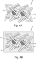
Fig. 4B is an isometric view of a pair of stellated octahedron reinforcing lattice cells ofFig. 4A with a matrix phase. -
Fig. 5A is an isometric view of another pair of stellated octahedron reinforcing lattice cells having stain limiting structures. -
Fig. 5B is an isometric view of another pair of stellated octahedron reinforcing lattice cells ofFig. 5A with a matrix phase. -
Fig. 6 is a isometric view of an exemplary a plurality of reinforcing lattice cells formed into a structure having face sheet. - Certain aerospace and other high performance applications require structures that can demonstrate a combination of light weight, high stiffness, strength, and toughness. In some applications, such structures can made from metallic or polymeric foam cores sandwiched between thin sheets of facing materials to form load bearing structures that may include aerodynamic surfaces. In other applications, the foam cores can be replaced by certain repeating three-dimensional (3-D) lattices structures, can be made from metallic or polymeric materials.
- Another option for such structures is to use a core of repeating 3-D lattice structures filled with a polymeric material, polymeric foam or metallic foam by themselves or surrounded by thin sheets of facing material to form reinforced sandwich materials. Such materials be used as load bearing structures and, if desired, may include aerodynamic surfaces. Surrounding or filling the repeating 3-D lattice structures, which can be made from metallic or polymeric materials, with a lower modulus, higher toughness, polymeric material, polymer foam, or metallic foam creates a composite material with the polymeric material or foam as a matrix phase and the 3-D lattice structures as a reinforcing phase. Such a composite can be designed to have high strength and stiffness and to have a very high global Poisson's ratio ≥ 1. When loaded in compression, contraction of the lattice elements around the tough matrix phase dissipates compressive forces and results in deformation with small strains. Such a composite will have high stiffness, high strength, and enhanced toughness.
- The performance of composite materials made from a repeating 3-D lattice structure having a polymeric material, polymeric foam, or metallic foam matrix phase can be enhanced by embedding a strain limiting structure into the matrix phase at or near the center of each 3-D lattice structure. The strain limiting structure, which can have a higher strength than the matrix phase, limits deformation of struts that make up the 3-D lattice structure, resulting in an overall higher ultimate strength for the composite material.
-
Figs. 1A and 1B show 3-D lattice structures that can be the basis for the repeating 3-D lattice structure used as the reinforcing phase in the composite materials of this disclosure. The repeating 3-D lattice structure can be formed from any polymeric or metallic material deemed appropriate for a particular application. For example, the repeating 3-D lattice structure can be made from steel, aluminum, titanium and alloys, including but not limited to Inco 625.Fig. 1A shows a 3-D lattice structure 10, in this case a stellated octahedron, formed with a plurality ofstruts 12, including two sets ofstiffening struts struts D lattice structure 10, it may be desirable to use an AM technique that can deposit multiple materials in a single build campaign. - While the
struts struts struts struts open spaces 16 that can be filled with a suitable matrix phase 18 (seeFig. 1B ), such as a polymeric material, a polymeric foam, or a metallic foam, to form a composite material. The polymeric material, a polymeric foam, or a metallic foam can be any such material useful as amatrix phase 18 for a particular application. As discussed above, in some examples the polymeric material, a polymeric foam, or a metallicfoam matrix phase 18 may have a lower modulus and higher toughness than the material used to make thestruts D lattice structure 10 is shown as a stellated octahedron other 3-D geometric shapes formed with a lattice structure can be used as the reinforcing phase in the composite materials of this disclosure. -
Figs. 2A and 2B show a 3-D lattice structure 20 similar to that depicted inFig. 1A with the reinforcingstruts 14 removed. The resulting 3-D lattice structure 20 includes a plurality ofstruts 22 with a single set of stiffening struts 23. Removing the reinforcing struts 24 from the 3-D lattice structure 10 ofFig. 1A to form 3-D lattice structure 20 is an example of how the 3-D lattice structures of this disclosure can be "tuned" to absorb more energy. Similar to the 3-D lattice structure 10 ofFig. 1A , the 3-D lattice structure 20 ofFig. 2A includeopen spaces 26 that can be filled with a suitable matrix phase 28 (seeFig. 2B ), such as a polymeric material, a polymeric foam, or a metallic foam, to form a composite material. Thestruts matrix 28 ofFigs. 2A and 2B can be made from the same materials and have the same properties as discussed above with regard to the comparable elements ofFigs. 1A and 1B and 2A/2B . While the 3-D lattice structure 20 is shown as a stellated octahedron other 3-D geometric shapes formed with a lattice structure can be used as the reinforcing phase in the composite materials of this disclosure. -
Figs. 3A and 3B show a 3-D lattice structure 30 similar to that depicted inFig. 2A that includes astrain limiting structure 39 positioned anopen space 36 at or near the center of the 3-D lattice structure 30 such thatstrain limiting structure 39 will be embedded in the matrix phase 38 (seeFig. 3B ) when the 3-D lattice structure 30 in filled with the matrix phase 38. Thestruts Figs. 3A and 3B can be made from the same materials and have the same properties as discussed above with regard to the comparable elements ofFigs. 1A/1B and 2A/2B . Thestrain limiting structure 39 ofFigs. 3A and 3B can have a higher strength (and in some examples, higher hardness) than the matrix 38 ofFig. 3B to limit further the deformation of thestruts D lattice structure 30. In some examples, thestrain limiting structure 39 of the 3-D lattice structure 30 can be hollow or formed as a composite material, provided that thestrain limiting structure 39 continues to have a higher strength (and in some examples, higher hardness) than the matrix 38 ofFig. 3B . As a result, a compressive or tensile load applied to the 3-D lattice structure 30 ofFig. 3B , will initially (and mostly) be absorbed/distributed by the Poisson effect created by deformation of the matrix phase 38. After some deformation of thelattice structure 30, thestruts strain limiting structure 39 in the center of each 3-D lattice structure 30. Thestrain limiting structure 39 would provide much more resistance to deformation than the surrounding matrix phase 38. This construction will give the 3-D lattice structure 30 a much higher ultimate strength because thestruts strain limiting structure 39 in the center of each 3-D lattice structure 30, thestruts -
Figs. 4A and 4B show a 3-D lattice structure 40 similar to that depicted inFigs. 3A and 3B that include two lattice structures. It should understood that a 3-D lattice structure like that shown inFigs. 4A and 4B can include any number of lattice structures as desirable for a particular application. Similar to the structures ofFigs. 3A and 3B , the 3-D lattice structure 40 includes astrain limiting structure 49 positioned anopen space 46 at or near the center of the 3-D lattice structure 40 such thatstrain limiting structure 49 will be embedded in the matrix phase 48 (seeFig. 4B ) when the 3-D lattice structure 40 in filled with the matrix phase 48. -
Figs. 5A and 5B show a 3-D lattice structure 50 similar to that depicted inFigs. 4A and 4B that include two lattice structures. As with the structures ofFigs. 4A and 4B , it should understood that a 3-D lattice structure like that shown inFigs. 5A and 5B can include any number of lattice structures as desirable for a particular application. Similar to the structures ofFigs. 4A and 34, the 3-D lattice structure 50 includes astrain limiting structure 59 positioned anopen space 56 at or near the center of the 3-D lattice structure 50 such that thestrain limiting structure 59 will be embedded in the matrix phase 58 (seeFig. 5B ) when the 3-D lattice structure 50 in filled with thematrix phase 58. The primary difference between the structures ofFigs. 5A and 5B andFigs. 4A and 4B is the shape of thestrain limiting structure 59 compared to thestrain limiting structure 49. These differences illustrate that the shape of any of thestrain limiting structures Figs. 3A/3B and4A/4B and the hemisphere depicted inFigs. 5A and 5B . -
Fig. 6 is a isometric view of an exemplary reinforcedstructure 60 having a plurality of 3-D lattice structures 62 formed into a sandwich structure having afirst face sheet 64 and asecond face sheet 66. In this view, the 3-D lattice structures 62 are shown as generic 3-D lattice structures to illustrate the variety of 3-D lattice structures that can be used to form such a structure. For example, the 3-D lattice structures 62 can be any of the 3-D lattice structures depicted inFigs. 1A-5A . The reinforcedstructure 60 can also include a matrix phase (not shown) as described with regard toFigs. 1B-5B . When reinforcedstructure 60 is made with structures similar to those depicted inFigs. 3B-5B , the full benefits described in this disclosure can be obtained. - For all of the examples discussed with regard to
Figs. 1A/1B, 2A/2B ,3A/3B ,4A/4B ,5A/5B , and6 , the desiredstrut strain limiting structures figs. 3A/3B ,4A/4B , and5A/5B , thestruts strain limiting structures struts strain limiting structures strain limiting structures matrix phase 38, 48, 58 and/or strain limitingstructures D lattice structures strain limiting structures strain limiting structures - The 3-D lattice structures of this disclosure are constructed to have a desirable combination of energy-absorption, toughness, ultimate strength, and stiffness. Using a multi-material AM machine (e.g., a multi-material 3D printer), the material used to form each component of the 3-D lattice structures can be selected to provide a selected level of performance. This can enable many custom uses or designs with very little added cost. The material use to form each component of the 3-D lattice structures can be printed and filled quickly, thus speeding up validation of any mechanical property analysis. The size, shape, and material of construction for each of the components (struts, matrix phase, and strain limiting structures) can be selected to meet requirements of particular applications. As discussed above, the strut cross-section can be non-circular and/or variable to achieve desired performance characteristics. Similarly, the strain limiting structures can be any shape and/or formed from a composite material. For example, the strain limiting structures can be gas filled to provide compressible cushion effect. The 3-D lattice structures can be formed from any suitable polyhedron shape. Combining metallic struts with a matrix phase made from a ductile metal with low melting point can allow for a metallic 3-D lattice structure useful for higher temperature applications.
- The following are non-exclusive descriptions of possible embodiments of the present invention.
- A three-dimensional (3-D) composite structure, comprising a 3-D lattice structure that comprises a plurality of struts; a matrix phase surrounding the 3-D lattice structure; and a strain limiting structure positioned at or near a center of the 3-D lattice structure.
- The 3-D composite structure of the preceding paragraph can optionally include, additionally and/or alternatively, any one or more of the following features, configurations and/or additional elements:
A further embodiment of the foregoing 3-D composite structure, wherein the 3-D lattice structure has a polyhedral shape. - A further embodiment of the foregoing 3-D composite structure, wherein the polyhedral shape is a stellated octahedron.
- A further embodiment of any of the foregoing 3-D composite structures, wherein the plurality of struts comprise a polymeric material or a metallic material.
- A further embodiment of any of the foregoing 3-D composite structures, wherein the matrix phase comprises a polymeric material, a polymeric foam, or a metallic foam.
- A further embodiment of any of the foregoing 3-D composite structures, wherein the matrix phase comprises a material having a lower modulus and higher toughness than a material used to form the plurality of struts.
- A further embodiment of any of the foregoing 3-D composite structures, wherein the strain limiting structure comprises a material having a higher strength that a material used to form the matrix phase.
- A further embodiment of any of the foregoing 3-D composite structures, wherein the strain limiting structure comprises a hollow structure or a composite material.
- A further embodiment of any of the foregoing 3-D composite structures, wherein the plurality of struts and the matrix phase are formed from fire-retardant materials.
- A further embodiment of any of the foregoing 3-D composite structures, wherein the strain limiting structure comprises an electrorheological material.
- A method of making a three-dimensional (3-D) composite structure, comprising the steps of: forming, using additive manufacturing techniques, a 3-D lattice structure that comprises a plurality of struts; forming, using additive manufacturing techniques, a matrix phase surrounding the 3-D lattice structure; and forming, using additive manufacturing techniques, a strain limiting structure positioned at or near a center of the 3-D lattice structure.
- The 3-method of the preceding paragraph can optionally include, additionally and/or alternatively, any one or more of the following features, configurations and/or additional elements:
A further embodiment of the foregoing method, wherein the 3-D lattice structure has a polyhedral shape. - A further embodiment of the foregoing method, wherein the polyhedral shape is a stellated octahedron.
- A further embodiment of any of the foregoing methods, wherein the plurality of struts comprise a polymeric material or a metallic material.
- A further embodiment of any of the foregoing methods, wherein the matrix phase comprises a polymeric material, a polymeric foam, or a metallic foam.
- A further embodiment of any of the foregoing methods, wherein the matrix phase comprises a material having a lower modulus and higher toughness than a material used to form the plurality of struts.
- A further embodiment of any of the foregoing methods, wherein the strain limiting structure comprises a material having a higher strength that a material used to form the matrix phase.
- A further embodiment of any of the foregoing methods, wherein the strain limiting structure comprises a hollow structure or a composite material.
- A further embodiment of any of the foregoing methods, wherein the plurality of struts and the matrix phase are formed from fire-retardant materials.
- A further embodiment of any of the foregoing methods, wherein the strain limiting structure comprises an electrorheological material.
- While the invention has been described with reference to an exemplary embodiment(s), it will be understood by those skilled in the art that various changes may be made and equivalents may be substituted for elements thereof without departing from the scope of the invention. In addition, many modifications may be made to adapt a particular situation or material to the teachings of the invention without departing from the essential scope thereof. Therefore, it is intended that the invention not be limited to the particular embodiment(s) disclosed, but that the invention will include all embodiments falling within the scope of the appended claims.
Claims (14)
- A three-dimensional (3-D) composite structure (60), comprising:a 3-D lattice structure (10; 20; 30; 40; 50; 62) that comprises a plurality of struts (12, 13, 14; 22, 23; 32, 33; 42; 52);a matrix phase (18; 28; 38; 48; 58) surrounding the 3-D lattice structure (10...62), wherein the matrix phase (18...58) comprises a material having a lower modulus and higher toughness than a material used to form the plurality of struts (12... 52); anda strain limiting structure (39; 49; 59) positioned at or near a center of the 3-D lattice structure (10...62), wherein the strain limiting structure (39; 49; 59) comprises a material having a higher strength than the material used to form the matrix phase (18... 58).
- The 3-D composite structure of claim 1, wherein the 3-D lattice structure (10... 62) has a polyhedral shape.
- The 3-D composite structure of claim 2, wherein the polyhedral shape is a stellated octahedron.
- The 3-D composite structure of any of the preceding claims, wherein the plurality of struts (12... 52) comprise a polymeric material or a metallic material.
- The 3-D composite structure of any of the preceding claims, wherein the matrix phase (18... 58) comprises a polymeric material, a polymeric foam, or a metallic foam.
- The 3-D composite structure of any of the preceding claims, wherein the strain limiting structure (39; 49; 59) comprises a hollow structure, a composite material, or an electrorheological material.
- The 3-D composite structure of any of the preceding claims, wherein the plurality of struts (12... 52) and the matrix phase (18; 59) are formed from fire-retardant materials.
- A method of making a three-dimensional (3-D) composite structure (60), comprising the steps of:forming, using additive manufacturing techniques, a 3-D lattice structure (10... 62) that comprises a plurality of struts (12... 52);forming, using additive manufacturing techniques, a matrix phase (18...58) surrounding the 3-D lattice structure (10...62), wherein the matrix phase (18... 58) comprises a material having a lower modulus and higher toughness than a material used to form the plurality of struts (12... 52); andforming, using additive manufacturing techniques, a strain limiting structure (39; 49; 59) positioned at or near a center of the 3-D lattice structure (10... 62), wherein the strain limiting structure (39; 49; 59) comprises a material having a higher strength than the material used to form the matrix phase (18... 58).
- The method of making 3-D composite structure of claim 8, wherein the 3-D lattice structure (10... 62) has a polyhedral shape.
- The method of making 3-D composite structure of claim 9, wherein the polyhedral shape is a stellated octahedron.
- The method of making 3-D composite structure of any of claims 8 to 10, wherein the plurality of struts (12... 52) comprise a polymeric material or a metallic material.
- The method of making 3-D composite structure of any of claims 8 to 11, wherein the matrix phase (18... 58) comprises a polymeric material, a polymeric foam, or a metallic foam.
- The method of making 3-D composite structure of any of claims 8 to 12, wherein the strain limiting structure (39; 49; 59) comprises a hollow structure, a composite material, or an electrorheological material.
- The method of making 3-D composite structure of any of claims 8 to 13, wherein the plurality of struts (12...52) and the matrix phase (18...58) are formed from fire-retardant materials.
Applications Claiming Priority (1)
| Application Number | Priority Date | Filing Date | Title |
|---|---|---|---|
| US202363529547P | 2023-07-28 | 2023-07-28 |
Publications (1)
| Publication Number | Publication Date |
|---|---|
| EP4497574A1 true EP4497574A1 (en) | 2025-01-29 |
Family
ID=92106863
Family Applications (1)
| Application Number | Title | Priority Date | Filing Date |
|---|---|---|---|
| EP24191258.3A Pending EP4497574A1 (en) | 2023-07-28 | 2024-07-26 | 3-d lattice reinforced composite with strain limiter |
Country Status (2)
| Country | Link |
|---|---|
| US (1) | US20250033278A1 (en) |
| EP (1) | EP4497574A1 (en) |
Families Citing this family (1)
| Publication number | Priority date | Publication date | Assignee | Title |
|---|---|---|---|---|
| US12446648B2 (en) * | 2021-06-03 | 2025-10-21 | Carbon, Inc. | Lofted lattice structures and methods of making the same |
Citations (2)
| Publication number | Priority date | Publication date | Assignee | Title |
|---|---|---|---|---|
| US20210213656A1 (en) * | 2019-02-13 | 2021-07-15 | Hyundai Motor Company | 3d-printed (lattice structured) metal - plastic matrix compound material |
| IT202100008423A1 (en) * | 2021-04-06 | 2022-10-06 | Olivieri Paolo | MODULAR SYSTEM FOR THE STORAGE OF THERMAL ENERGY. |
Family Cites Families (3)
| Publication number | Priority date | Publication date | Assignee | Title |
|---|---|---|---|---|
| US20160027425A1 (en) * | 2013-03-13 | 2016-01-28 | Milwaukee School Of Engineering | Lattice structures |
| WO2016171711A1 (en) * | 2015-04-24 | 2016-10-27 | Halliburton Energy Services, Inc. | Mesoscale reinforcement of metal matrix composites |
| US10813407B2 (en) * | 2015-11-30 | 2020-10-27 | Nike, Inc. | Electrorheological fluid structure having strain relief element and method of fabrication |
-
2024
- 2024-06-14 US US18/743,509 patent/US20250033278A1/en active Pending
- 2024-07-26 EP EP24191258.3A patent/EP4497574A1/en active Pending
Patent Citations (2)
| Publication number | Priority date | Publication date | Assignee | Title |
|---|---|---|---|---|
| US20210213656A1 (en) * | 2019-02-13 | 2021-07-15 | Hyundai Motor Company | 3d-printed (lattice structured) metal - plastic matrix compound material |
| IT202100008423A1 (en) * | 2021-04-06 | 2022-10-06 | Olivieri Paolo | MODULAR SYSTEM FOR THE STORAGE OF THERMAL ENERGY. |
Also Published As
| Publication number | Publication date |
|---|---|
| US20250033278A1 (en) | 2025-01-30 |
Similar Documents
| Publication | Publication Date | Title |
|---|---|---|
| Zhang et al. | Investigation of bird-strike resistance of composite sandwich curved plates with lattice/foam cores | |
| CN112848553B (en) | Reinforced single cell structure, preparation method and application thereof, and sandwich board | |
| Hassanpour Roudbeneh et al. | Experimental investigation of impact loading on honeycomb sandwich panels filled with foam | |
| US20200276783A1 (en) | 3-D Honeycomb Foam Structure | |
| Zaid et al. | Sandwich structure based on corrugated-core: a review | |
| JP2019081361A (en) | Modular mold for manufacturing fiber reinforcement panel and manufacturing method of fiber reinforcement panel | |
| US20250033278A1 (en) | 3-d lattice reinforced composite with strain limiter | |
| Harland et al. | An experimental and numerical investigation of a novel 3D printed sandwich material for motorsport applications | |
| JP2007517687A (en) | High impact strength elastic mixed fiber metal laminate | |
| EP3345754A1 (en) | Sandwich panel with recessed channel network | |
| US5746537A (en) | Crash-energy absorbing composite structure and method of fabrication | |
| CA2960779C (en) | Honeycomb, in particular deformable honeycomb, for lightweight components, corresponding production method and sandwich component | |
| US20180297685A1 (en) | Shielded Structure for Aircraft | |
| Pandyaraj et al. | Experimental investigation of compression strength in novel sandwich structure | |
| US20250062057A1 (en) | Variable damping in composite material | |
| CA2929869C (en) | Crash energy absorbing part | |
| EP1726787A2 (en) | Containment casing for an aircraft engine | |
| EP4737120A1 (en) | Variable damping in composite material | |
| US8663812B2 (en) | Method for preparing a cellular material based on hollow metal beads | |
| EP3477144B1 (en) | Rotary joint | |
| Monkova et al. | Tensile Behaviour of a 3D printed lattice structure | |
| Bednarcyk et al. | Preliminary Structural Sizing and Alternative Material Trade Study for the CEV Crew Module | |
| Shah et al. | Effect of additively manufactured core geometry on the transverse compression performance of foam‐filled sandwich composite structures | |
| US20200198227A1 (en) | Structures made via additive manufacturing having multiple load paths | |
| KR102727276B1 (en) | Composite structures panel and manufacturing method the same |
Legal Events
| Date | Code | Title | Description |
|---|---|---|---|
| PUAI | Public reference made under article 153(3) epc to a published international application that has entered the european phase |
Free format text: ORIGINAL CODE: 0009012 |
|
| STAA | Information on the status of an ep patent application or granted ep patent |
Free format text: STATUS: THE APPLICATION HAS BEEN PUBLISHED |
|
| AK | Designated contracting states |
Kind code of ref document: A1 Designated state(s): AL AT BE BG CH CY CZ DE DK EE ES FI FR GB GR HR HU IE IS IT LI LT LU LV MC ME MK MT NL NO PL PT RO RS SE SI SK SM TR |
|
| STAA | Information on the status of an ep patent application or granted ep patent |
Free format text: STATUS: REQUEST FOR EXAMINATION WAS MADE |
|
| 17P | Request for examination filed |
Effective date: 20250723 |
|
| STAA | Information on the status of an ep patent application or granted ep patent |
Free format text: STATUS: EXAMINATION IS IN PROGRESS |
|
| 17Q | First examination report despatched |
Effective date: 20251023 |