EP4497556A1 - A wooden handle pocket knife - Google Patents
A wooden handle pocket knife Download PDFInfo
- Publication number
- EP4497556A1 EP4497556A1 EP23187425.6A EP23187425A EP4497556A1 EP 4497556 A1 EP4497556 A1 EP 4497556A1 EP 23187425 A EP23187425 A EP 23187425A EP 4497556 A1 EP4497556 A1 EP 4497556A1
- Authority
- EP
- European Patent Office
- Prior art keywords
- blade
- connecting end
- shaft
- hole
- ridged surface
- Prior art date
- Legal status (The legal status is an assumption and is not a legal conclusion. Google has not performed a legal analysis and makes no representation as to the accuracy of the status listed.)
- Granted
Links
Images

Classifications
-
- B—PERFORMING OPERATIONS; TRANSPORTING
- B26—HAND CUTTING TOOLS; CUTTING; SEVERING
- B26B—HAND-HELD CUTTING TOOLS NOT OTHERWISE PROVIDED FOR
- B26B1/00—Hand knives with adjustable blade; Pocket knives
- B26B1/02—Hand knives with adjustable blade; Pocket knives with pivoted blade
- B26B1/04—Hand knives with adjustable blade; Pocket knives with pivoted blade lockable in adjusted position
- B26B1/046—Hand knives with adjustable blade; Pocket knives with pivoted blade lockable in adjusted position with a locking member acting in axial direction parallel to the pivot axis of the blade
-
- B—PERFORMING OPERATIONS; TRANSPORTING
- B26—HAND CUTTING TOOLS; CUTTING; SEVERING
- B26B—HAND-HELD CUTTING TOOLS NOT OTHERWISE PROVIDED FOR
- B26B1/00—Hand knives with adjustable blade; Pocket knives
- B26B1/02—Hand knives with adjustable blade; Pocket knives with pivoted blade
- B26B1/04—Hand knives with adjustable blade; Pocket knives with pivoted blade lockable in adjusted position
- B26B1/044—Hand knives with adjustable blade; Pocket knives with pivoted blade lockable in adjusted position by a spring tongue snapping behind or into the tang of the blade from a side part of the handle
Definitions
- the invention relates to wooden handle pocket knives, and in particular to wooden handle pocket knifes with a linear locking mechanism.
- a pocket knife is a well-known device which is intended to be carried in a folded state. Main requirement for such knife in folded state to remain folded until a user acts upon the locking mechanism to unfold the knife and in unfolded state the knife has to remain unfolded until a user acts upon the locking mechanism to fold the knife. If the knife locking mechanism is compromised the blade might unfold when carried and damage the carrier's belongings or injure the carrier himself. The same is true when the knife blade does not stay securely locked in the unfolded state of has freedom to move when locked.
- Wooden handle type pocket knives usually have a cutting blade attached to a wooden handle via a liner lock assembly which also serves as locking means for locking the blade in folded and unfolded states. Main elements of the liner lock assembly are disposed in the wooden handle and some around the handle at the blade attachment to the handle end.
- a Portuguese patent No. PT110858 discloses a wooden handle pocket knife comprising a handle with a longitudinal slot for stowing a blade in a folded state, a blade, a liner lock and release plate, a bolster, a rivet for securing the bolster on the handle and for interconnecting the bolster, the wooden handle, the blade and the liner lock and release plate.
- Main disadvantage of the disclosed wooden handle pocket knife is that deformation of the wooden handle and the bolster due to variation of humidity, temperature and mechanical interaction between blade and bolster to which the pocket knife is subjected conditions the lock and release plate to faulty functioning and in particular to release the locked blade when the release action is not conditioned by a user. Such a knife is unsafe to carry and to use as the carrier and/or a user might get injured if the blade is self-unlocked.
- the present invention is dedicated to overcoming of the above shortcomings and for producing further advantages over prior art.
- the invention discloses a wooden handle pocket knife comprising a blade (1) comprising a connecting end (1.3) with a hole (1.3.1) for connecting the blade (1) to a wooden handle (2) comprising a blade attachment section (2.2) with two branches (2.2.1, 2.2.2) each comprising an axially aligned hole (2.2.3) for aligning with the hole (1.3.1) in the connecting end (1.3) for inserting a shaft (7.2).
- the knife also comprises a liner lock and release plate (3) comprising a hole (3.1) for alignment with the hole (1.3.1) in the connecting end (1.3) and the holes (2.2.3) of the branches (2.2.1, 2.2.2) and for inserting the shaft (7.2).
- the knife also comprises a bolster (4) comprising holes (4.1) for alignment with the hole (1.3.1) in the connecting end (1.3) of the blade (1) and the holes (2.2.3) of the branches (2.2.1, 2.2.2) and inserting the shaft (7.2).
- the knife further comprises a washer (5), a pin (6), a screw (7.1) and the shaft (7.2) is a threaded shaft.
- the connecting end (1.3) of the blade (1) further comprises a notch (1.3.2) for abutting the pin (6) when the blade (1) is in folded state and a first ridged surface on back edge (1.3.3) of the connecting end (1.3) for interacting with another ridged surface, where the crests of the first ridged surface are positioned in recesses of the second ridged surface and the crests of the second ridged surface are positioned in the recesses of the first ridged surface when the blade (1) is in unfolded and locked state.
- Each branch (2.2.1, 2.2.2) comprises a further hole for inserting the pin (6).
- the liner lock and release plate (3) further comprises a hole (3.2) for inserting the pin (6), a second ridged surface formed on front edge (3.3.1.2) of free end (3.3.1) of the springed flap (3.3) for abutting the first ridged surface on the back edge (1.3.3) of the connecting end (1.3) of the blade (1) when the blade (1) is in unfolded and locked state, an L shaped end (3.4) comprising an upper part (3.4.2) protruding at essentially 90° from plane of main body of the liner lock and release plate (3) and comprising a front edge (3.4.2.1) for interacting with upper back edge (1.1.1) of the main body (1.1) of the blade (1) adjacent to the upper edge (1.3.5) of the connecting end (1.3) of the blade (1).
- the washer (5) is disposed on the shaft (7.2) between second side (1.3.7) of the connecting end (1.3) of the blade (1), which is directed to inner side of the second wooden branch (2.2.2), and the second wooden branch (2.2.2) inner side, which is opposite to outer side interacting with inner side of the bolster (4), where first side (1.3.6) of the connecting end (1.3) of the blade (1) is directed towards second side (3.5) of the liner lock and release plate (3).
- the blade (1) is interacting only with the liner lock and release plate (3) at two points which is secured to the wooden handle (2) at two points, by a shaft (7.2) and a pin (6), decreasing or eliminating influence of deformation of the wooden handle (2) and the bolster (4) to the security of the knife in both unfolded and locked position and in folded position.
- the wooden handle pocket knife comprises a blade (1), a wooden handle (2), a liner lock and release plate (3), a bolster (4), a washer (5), a pin (6), a screw (7.1) and a treaded shaft (7.2).
- the blade (1) comprises a main body (1.1) comprising a cutting edge (1.2) and a connecting end (1.3), for connecting the blade (1) to the wooden handle (2), and an upper back edge (1.1.1) adjacent and at essentially right angle to upper edge (1.3.5) of the connecting end (1.3) of the blade (1).
- the connecting end (1.3) comprises a first hole (1.3.1), for inserting the threaded shaft (7.2), a notch (1.3.2) for abutting the pin (6).
- Back edge (1.3.3) of the connecting end (1.3) comprises a first ridged surface. The ridges are formed essentially parallel to the orientation of the first hole (1.3.1) or at an angle with respect to the orientation direction of the first hole (1.3.1).
- the notch (1.3.2) is formed at the bottom edge (1.3.4) of the connecting end (1.3) and closer to the main body (1.1) than the first hole (1.3.1).
- the radius of the notch (1.3.2) is preferably essentially the same as the radius of the pin (6) allowing the pin (6) to fit into the notch (1.3.2) and avoid side motions of the blade (1) relatively to the pin (6) length when the blade (1) is in folded position.
- the wooden handle (2) comprises a holding section (2.1), for positioning in a user's palm, a blade attachment section (2.2), a longitudinal slot (2.3) for locating a liner lock and release plate (3) and for stowing the blade (1) in a folded state.
- the blade attachment section (2.2) is divided by a gap into two branches (2.2.1, 2.2.2).
- Each branch (2.2.1, 2.2.2) comprises an axially aligned second hole (2.2.3) for locating the threaded shaft (7.2).
- Each branch (2.2.1, 2.2.2) further comprises an axially aligned third hole (2.2.4) for locating the pin (6).
- the second holes (2.2.3) are bored in the branches (2.2.1, 2.2.2) preferably at the centre from sides of each branch (2.2.1, 2.2.2).
- the position of the second holes (2.2.3) can also be off centre.
- the third holes (2.2.4) are formed at upper part of the blade attachment section (2.2) of the wooden handle (2) near the holding section (2.1). In all cases the second holes (2.2.3) are positioned with respect to the third holes (2.2.4) so that the first hole (1.3.1) would align with the second holes (2.2.3) when the blade (1) is attached to the blade attachment section (2.2) of the wooden handle (2) when the threaded shaft (7.2) is inserted through the second holes (2.2.3) of the each branch (2.2.1, 2.2.2) and the first hole (1.3.1) of the connecting end (1.3) of the blade (1), wherein the pin (6) when inserted into the third holes (2.2.4) would receive the notch (1.3.2) and fit in the notch (1.3.2) essentially without any gap between outer surface of the pin (6) and inner surface of the notch (1.3.2) when the blade (1) is in the folded position and housed in the longitudinal slot (2.3) of the wooden handle (2).
- the threaded shaft (7.2) has a smooth outer surface on which the blade (1) rotates when the shaft (7.2) is inserted into the first hole (1.3.1) of the connecting end (1.3) of the blade (1).
- the thread is formed inside the shaft (7.2) at one end for inserting a screw (7.1).
- the other end of the shaft has a widening obstructing the shafts through motion through the second holes (2.2.3) and the fourth holes (4.1) in the bolster (4).
- the bolster (4) has a cylindrical body and comprises fourth holes (4.1) on opposite sides and in line one with another and when the knife is assembled the fourth holes (4.1) are also in line with the first hole (1.3.1) of the connecting end (1.3) of the blade (1) and the second holes (2.2.3) of the branches (2.2.1, 2.2.2) allowing the threaded shaft (7.2) to be inserted through the first hole (1.3.1), the second holes (2.2.3), the fourth holes (4.1) and the fifth hole (3.1) for pivoting motion of the blade (1) around the shaft (7.2) when the knife is folded or unfolded.
- the bolster (4) encloses the blade attachment section (2.2) of the handle (2) by surrounding the said section (2.2) and covers the third holes (2.2.4) of the branches (2.2.1, 2.2.2).
- the bolster (4) prevents the branches (2.2.1, 2.2.2) and the gap between the branches (2.2.1, 2.2.2) from deforming as well as prevents the pin (6) from sliding out of the third holes (2.2.4).
- the liner lock and release plate (3) comprises a fifth hole (3.1) for alignment with the first hole (1.3.1) of the connecting end (1.3) of the blade (1) and the second holes (2.2.3) of the branches (2.2.1, 2.2.2) when the blade (1) is attached to the blade attachment section (2.2) of the handle (2) by the threaded shaft (7.2).
- the liner lock and release plate (3) further comprise a sixth hole (3.2) for alignment with the third holes (2.2.4) of the branches (2.2.1, 2.2.2) when the pin (6) is inserted through the third holes (2.2.4) and the sixth hole (3.2).
- the liner lock and release plate (3) also comprise a lock and release springed flap (3.3).
- the springed flap (3.3) comprises a free end (3.3.1) comprising a protruding section (3.3.1.1) for manipulating by a user's finger for unlocking the blade (1) by a sideway motion when the blade (1) is in unfolded state.
- the springed flap (3.3) comprises a second ridged surface formed on front edge (3.3.1.2) of the free end (3.3.1) of the springed flap (3.3) for abutting the first ridged surface on the back edge (1.3.3) of the connecting end (1.3) when the blade (1) is in unfolded and locked state.
- the first ridged surface and the second ridged surface are formed so that when the blade (1) is in unfolded and locked state the crests of the first ridged surface goes into recesses of the second ridged surface and the crests of the second ridged surface goes in the recesses of the first ridged surface thus interlocking the blade (1) and the liner lock and release plate (3) and eliminating any free motion of the blade up and down when the blade (1) is in the locked state.
- the liner lock and release plate (3) further comprise an L shaped end (3.4) having a lower part (3.4.1) constituting part of liner lock and release plate (3) main body and an upper part (3.4.2) protruding at essentially 90° from plane of the main body of the liner lock and release plate (3).
- the protruding upper part (3.4.2) comprises a front edge (3.4.2.1) for abutting upper back edge (1.1.1) of the main body (1.1) of the blade (1) adjacent to the upper edge (1.3.5) of the connecting end (1.3) of the blade (1) when the blade (1) is fully unfolded.
- the interaction of the upper back edge (1.1.1) of the main body (1.1) of the blade (1) and the front edge (3.4.2.1) of the protruding upper part (3.4.2) of the liner lock and release plate (3) stops the blade (1) in a precise position for locking every time the blade (1) is being opened, preventing the blade (1) from abutting the bolster (4).
- the first ridged surface at the back edge (1.3.3) of the connecting end (1.3) of the blade (1) is locked with second ridged surface of the springed flap (3.3) and the upper back edge (1.1.1) of the main body (1.1) of the blade (1) is abutting the front edge (3.4.2.1) of the protruding upper part (3.4.2) of the liner lock and release plate (3) the blade (1) thus preventing from any degree of up and down motion of the blade (1) in the plane of folding and unfolding of the knife. Further it also prevents the upper edge (1.3.5) of the connecting end (1.3) from interacting with the protruding upper part (3.4.2) of the L shaped end (3.4) of the liner lock and release plate (3).
- the blade (1) is interacting only with the liner lock and release plate (3) which is secured to the wooden handle (2) at two points, by a shaft (7.2) and a pin (6), decreasing or eliminating influence of deformation of the wooden handle (2) and the bolster (4) to the security of the knife in both unfolded and locked position and in folded position.
- the washer (5) is disposed on the shaft (7.2) between second side (1.3.7) of the connecting end (1.3) of the blade (1), which is directed to inner side of the second wooden branch (2.2.2), and the second wooden branch (2.2.2) inner side which is opposite to outer side interacting with inner side of the bolster (4).
- the first side (1.3.6) of the connecting end (1.3) of the blade (1) is directed towards the second side (3.5) of the liner lock and release plate (3) where the first side, opposite the second side (3.5) is directed towards inner side of the first wooden branch (2.2.1).
- the blade (1) When the blade (1) is pivoted for folding or unfolding the first side (1.3.6) of the connecting end (1.3) of the blade (1) interacts with the second side (3.5) and springed flap (3.3) of the liner lock and release plate (3) and the and the second side (1.3.7) of the connecting end (1.3) of the blade (1) interacts with inner side of the second wooden branch (2.2.2) via the washer (5) where degree of friction arises between said elements (1.3.6, 1.3.7, 2.2.2, 3.3, 3.5, 5) from tightening the screw (7.1) and the threaded shaft (7.2).
- the user When the pocket knife is closed, the user needs both hands to open the blade.
- One hand secures the handle (2) and another hand opens the blade (1) by gripping a part of the blade (1) protruding from the wooden handle (2).
- the a click sound is generated (1) by interaction of the main body of the blade (1) and the liner lock and release plate (3), warning the user that the blade (1) is locked and secured for using.
Landscapes
- Life Sciences & Earth Sciences (AREA)
- Forests & Forestry (AREA)
- Engineering & Computer Science (AREA)
- Mechanical Engineering (AREA)
- Knives (AREA)
Abstract
Description
- The invention relates to wooden handle pocket knives, and in particular to wooden handle pocket knifes with a linear locking mechanism.
- A pocket knife is a well-known device which is intended to be carried in a folded state. Main requirement for such knife in folded state to remain folded until a user acts upon the locking mechanism to unfold the knife and in unfolded state the knife has to remain unfolded until a user acts upon the locking mechanism to fold the knife. If the knife locking mechanism is compromised the blade might unfold when carried and damage the carrier's belongings or injure the carrier himself. The same is true when the knife blade does not stay securely locked in the unfolded state of has freedom to move when locked.
- Wooden handle type pocket knives usually have a cutting blade attached to a wooden handle via a liner lock assembly which also serves as locking means for locking the blade in folded and unfolded states. Main elements of the liner lock assembly are disposed in the wooden handle and some around the handle at the blade attachment to the handle end.
- A Portuguese patent No.
PT110858 - The present invention is dedicated to overcoming of the above shortcomings and for producing further advantages over prior art.
- The invention discloses a wooden handle pocket knife comprising a blade (1) comprising a connecting end (1.3) with a hole (1.3.1) for connecting the blade (1) to a wooden handle (2) comprising a blade attachment section (2.2) with two branches (2.2.1, 2.2.2) each comprising an axially aligned hole (2.2.3) for aligning with the hole (1.3.1) in the connecting end (1.3) for inserting a shaft (7.2). The knife also comprises a liner lock and release plate (3) comprising a hole (3.1) for alignment with the hole (1.3.1) in the connecting end (1.3) and the holes (2.2.3) of the branches (2.2.1, 2.2.2) and for inserting the shaft (7.2). The knife also comprises a bolster (4) comprising holes (4.1) for alignment with the hole (1.3.1) in the connecting end (1.3) of the blade (1) and the holes (2.2.3) of the branches (2.2.1, 2.2.2) and inserting the shaft (7.2). The knife further comprises a washer (5), a pin (6), a screw (7.1) and the shaft (7.2) is a threaded shaft. The connecting end (1.3) of the blade (1) further comprises a notch (1.3.2) for abutting the pin (6) when the blade (1) is in folded state and a first ridged surface on back edge (1.3.3) of the connecting end (1.3) for interacting with another ridged surface, where the crests of the first ridged surface are positioned in recesses of the second ridged surface and the crests of the second ridged surface are positioned in the recesses of the first ridged surface when the blade (1) is in unfolded and locked state. Each branch (2.2.1, 2.2.2) comprises a further hole for inserting the pin (6). The liner lock and release plate (3) further comprises a hole (3.2) for inserting the pin (6), a second ridged surface formed on front edge (3.3.1.2) of free end (3.3.1) of the springed flap (3.3) for abutting the first ridged surface on the back edge (1.3.3) of the connecting end (1.3) of the blade (1) when the blade (1) is in unfolded and locked state, an L shaped end (3.4) comprising an upper part (3.4.2) protruding at essentially 90° from plane of main body of the liner lock and release plate (3) and comprising a front edge (3.4.2.1) for interacting with upper back edge (1.1.1) of the main body (1.1) of the blade (1) adjacent to the upper edge (1.3.5) of the connecting end (1.3) of the blade (1). The washer (5) is disposed on the shaft (7.2) between second side (1.3.7) of the connecting end (1.3) of the blade (1), which is directed to inner side of the second wooden branch (2.2.2), and the second wooden branch (2.2.2) inner side, which is opposite to outer side interacting with inner side of the bolster (4), where first side (1.3.6) of the connecting end (1.3) of the blade (1) is directed towards second side (3.5) of the liner lock and release plate (3).
- The blade (1) is interacting only with the liner lock and release plate (3) at two points which is secured to the wooden handle (2) at two points, by a shaft (7.2) and a pin (6), decreasing or eliminating influence of deformation of the wooden handle (2) and the bolster (4) to the security of the knife in both unfolded and locked position and in folded position.
- Features of the invention believed to be novel and inventive are set forth with particularity in the appended claims. The invention itself, however, may be best understood by reference to the following detailed description of the invention, which describes exemplary embodiments, given in non-restrictive examples, of the invention, taken in conjunction with the accompanying drawings, in which:
-
Fig. 1 shows exploded view of the wooden handle pocket knife according to the invention. -
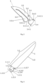
Fig. 2 shows a liner lock and release plate of the wooden handle pocket knife according to the invention. -
Fig. 3 shows a blade of the wooden handle pocket knife according to the invention. -
Fig. 4 shows interaction points of the blade and the liner lock and release plate of the wooden handle pocket knife according to the invention. -
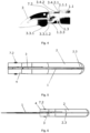
Fig. 5 shows the knife in folded state according to the invention. -
Fig. 6 shows the knife in unfolded state according to the invention. - Preferred embodiments of the invention will be described herein below with reference to the drawings. Each figure contains the same numbering for the same or equivalent element.
- It should be understood that numerous specific details are presented in order to provide a complete and comprehensible description of the invention embodiment. However, the person skilled in art will understand that the embodiment examples do not limit the application of the invention which can be implemented without these specific instructions. Well-known methods, procedures and components have not been described in detail for the embodiment to avoid misleading. Furthermore, this description should not be considered to be constraining the invention to given embodiment examples but only as one of possible implementations of the invention.
- According to embodiment of the invention the wooden handle pocket knife comprises a blade (1), a wooden handle (2), a liner lock and release plate (3), a bolster (4), a washer (5), a pin (6), a screw (7.1) and a treaded shaft (7.2).
- The blade (1) comprises a main body (1.1) comprising a cutting edge (1.2) and a connecting end (1.3), for connecting the blade (1) to the wooden handle (2), and an upper back edge (1.1.1) adjacent and at essentially right angle to upper edge (1.3.5) of the connecting end (1.3) of the blade (1). The connecting end (1.3) comprises a first hole (1.3.1), for inserting the threaded shaft (7.2), a notch (1.3.2) for abutting the pin (6). Back edge (1.3.3) of the connecting end (1.3) comprises a first ridged surface. The ridges are formed essentially parallel to the orientation of the first hole (1.3.1) or at an angle with respect to the orientation direction of the first hole (1.3.1). The notch (1.3.2) is formed at the bottom edge (1.3.4) of the connecting end (1.3) and closer to the main body (1.1) than the first hole (1.3.1). The radius of the notch (1.3.2) is preferably essentially the same as the radius of the pin (6) allowing the pin (6) to fit into the notch (1.3.2) and avoid side motions of the blade (1) relatively to the pin (6) length when the blade (1) is in folded position.
- The wooden handle (2) comprises a holding section (2.1), for positioning in a user's palm, a blade attachment section (2.2), a longitudinal slot (2.3) for locating a liner lock and release plate (3) and for stowing the blade (1) in a folded state. The blade attachment section (2.2) is divided by a gap into two branches (2.2.1, 2.2.2). Each branch (2.2.1, 2.2.2) comprises an axially aligned second hole (2.2.3) for locating the threaded shaft (7.2). Each branch (2.2.1, 2.2.2) further comprises an axially aligned third hole (2.2.4) for locating the pin (6). The second holes (2.2.3) are bored in the branches (2.2.1, 2.2.2) preferably at the centre from sides of each branch (2.2.1, 2.2.2). The position of the second holes (2.2.3) can also be off centre. The third holes (2.2.4) are formed at upper part of the blade attachment section (2.2) of the wooden handle (2) near the holding section (2.1). In all cases the second holes (2.2.3) are positioned with respect to the third holes (2.2.4) so that the first hole (1.3.1) would align with the second holes (2.2.3) when the blade (1) is attached to the blade attachment section (2.2) of the wooden handle (2) when the threaded shaft (7.2) is inserted through the second holes (2.2.3) of the each branch (2.2.1, 2.2.2) and the first hole (1.3.1) of the connecting end (1.3) of the blade (1), wherein the pin (6) when inserted into the third holes (2.2.4) would receive the notch (1.3.2) and fit in the notch (1.3.2) essentially without any gap between outer surface of the pin (6) and inner surface of the notch (1.3.2) when the blade (1) is in the folded position and housed in the longitudinal slot (2.3) of the wooden handle (2).
- The threaded shaft (7.2) has a smooth outer surface on which the blade (1) rotates when the shaft (7.2) is inserted into the first hole (1.3.1) of the connecting end (1.3) of the blade (1). The thread is formed inside the shaft (7.2) at one end for inserting a screw (7.1). The other end of the shaft has a widening obstructing the shafts through motion through the second holes (2.2.3) and the fourth holes (4.1) in the bolster (4).
- The bolster (4) has a cylindrical body and comprises fourth holes (4.1) on opposite sides and in line one with another and when the knife is assembled the fourth holes (4.1) are also in line with the first hole (1.3.1) of the connecting end (1.3) of the blade (1) and the second holes (2.2.3) of the branches (2.2.1, 2.2.2) allowing the threaded shaft (7.2) to be inserted through the first hole (1.3.1), the second holes (2.2.3), the fourth holes (4.1) and the fifth hole (3.1) for pivoting motion of the blade (1) around the shaft (7.2) when the knife is folded or unfolded. The bolster (4) encloses the blade attachment section (2.2) of the handle (2) by surrounding the said section (2.2) and covers the third holes (2.2.4) of the branches (2.2.1, 2.2.2). The bolster (4) prevents the branches (2.2.1, 2.2.2) and the gap between the branches (2.2.1, 2.2.2) from deforming as well as prevents the pin (6) from sliding out of the third holes (2.2.4).
- The liner lock and release plate (3) comprises a fifth hole (3.1) for alignment with the first hole (1.3.1) of the connecting end (1.3) of the blade (1) and the second holes (2.2.3) of the branches (2.2.1, 2.2.2) when the blade (1) is attached to the blade attachment section (2.2) of the handle (2) by the threaded shaft (7.2). The liner lock and release plate (3) further comprise a sixth hole (3.2) for alignment with the third holes (2.2.4) of the branches (2.2.1, 2.2.2) when the pin (6) is inserted through the third holes (2.2.4) and the sixth hole (3.2). The liner lock and release plate (3) also comprise a lock and release springed flap (3.3). The springed flap (3.3) comprises a free end (3.3.1) comprising a protruding section (3.3.1.1) for manipulating by a user's finger for unlocking the blade (1) by a sideway motion when the blade (1) is in unfolded state. The springed flap (3.3) comprises a second ridged surface formed on front edge (3.3.1.2) of the free end (3.3.1) of the springed flap (3.3) for abutting the first ridged surface on the back edge (1.3.3) of the connecting end (1.3) when the blade (1) is in unfolded and locked state. The first ridged surface and the second ridged surface are formed so that when the blade (1) is in unfolded and locked state the crests of the first ridged surface goes into recesses of the second ridged surface and the crests of the second ridged surface goes in the recesses of the first ridged surface thus interlocking the blade (1) and the liner lock and release plate (3) and eliminating any free motion of the blade up and down when the blade (1) is in the locked state. The liner lock and release plate (3) further comprise an L shaped end (3.4) having a lower part (3.4.1) constituting part of liner lock and release plate (3) main body and an upper part (3.4.2) protruding at essentially 90° from plane of the main body of the liner lock and release plate (3). The protruding upper part (3.4.2) comprises a front edge (3.4.2.1) for abutting upper back edge (1.1.1) of the main body (1.1) of the blade (1) adjacent to the upper edge (1.3.5) of the connecting end (1.3) of the blade (1) when the blade (1) is fully unfolded. The interaction of the upper back edge (1.1.1) of the main body (1.1) of the blade (1) and the front edge (3.4.2.1) of the protruding upper part (3.4.2) of the liner lock and release plate (3) stops the blade (1) in a precise position for locking every time the blade (1) is being opened, preventing the blade (1) from abutting the bolster (4).
- When the knife is in unfolded and locked state the first ridged surface at the back edge (1.3.3) of the connecting end (1.3) of the blade (1) is locked with second ridged surface of the springed flap (3.3) and the upper back edge (1.1.1) of the main body (1.1) of the blade (1) is abutting the front edge (3.4.2.1) of the protruding upper part (3.4.2) of the liner lock and release plate (3) the blade (1) thus preventing from any degree of up and down motion of the blade (1) in the plane of folding and unfolding of the knife. Further it also prevents the upper edge (1.3.5) of the connecting end (1.3) from interacting with the protruding upper part (3.4.2) of the L shaped end (3.4) of the liner lock and release plate (3). Further it also prevents any part of the blade (1) from interacting with the bolster (4). The blade (1) is interacting only with the liner lock and release plate (3) which is secured to the wooden handle (2) at two points, by a shaft (7.2) and a pin (6), decreasing or eliminating influence of deformation of the wooden handle (2) and the bolster (4) to the security of the knife in both unfolded and locked position and in folded position.
- The washer (5) is disposed on the shaft (7.2) between second side (1.3.7) of the connecting end (1.3) of the blade (1), which is directed to inner side of the second wooden branch (2.2.2), and the second wooden branch (2.2.2) inner side which is opposite to outer side interacting with inner side of the bolster (4). The first side (1.3.6) of the connecting end (1.3) of the blade (1) is directed towards the second side (3.5) of the liner lock and release plate (3) where the first side, opposite the second side (3.5) is directed towards inner side of the first wooden branch (2.2.1). When the blade (1) is pivoted for folding or unfolding the first side (1.3.6) of the connecting end (1.3) of the blade (1) interacts with the second side (3.5) and springed flap (3.3) of the liner lock and release plate (3) and the and the second side (1.3.7) of the connecting end (1.3) of the blade (1) interacts with inner side of the second wooden branch (2.2.2) via the washer (5) where degree of friction arises between said elements (1.3.6, 1.3.7, 2.2.2, 3.3, 3.5, 5) from tightening the screw (7.1) and the threaded shaft (7.2).
- When the pocket knife is closed, the user needs both hands to open the blade. One hand secures the handle (2) and another hand opens the blade (1) by gripping a part of the blade (1) protruding from the wooden handle (2). This is a very smooth operation with a low retention feeling of the blade (1) made by the constant pressure on the sides (1.3.6, 1.3.7) of the connecting end (1.3) of the blade (1). This pressure keeps the blade (1) closed and prevents the blade (1) to open accidently.
- Further, when the user opens the pocket knife and when the blade (1) goes into completely unfolded position, the a click sound is generated (1) by interaction of the main body of the blade (1) and the liner lock and release plate (3), warning the user that the blade (1) is locked and secured for using.
- Although numerous characteristics and advantages together with structural details and features have been listed in the present description of the invention, the description is provided as an example fulfilment of the invention. Without departing from the principles of the invention, there may be changes in the details, especially in the form, size and layout, in accordance with most widely understood meanings of the concepts and definitions used in claims.
Claims (3)
- A wooden handle pocket knife comprising a blade (1) comprising a main body (1.1) comprising a connecting end (1.3) with a hole (1.3.1) for connecting the blade (1) to a wooden handle (2) comprising a blade attachment section (2.2) with two branches (2.2.1, 2.2.2) each comprising an axially aligned hole (2.2.3) for aligning with the hole (1.3.1) in the connecting end (1.3) for inserting a shaft (7.2), the knife also comprising a liner lock and release plate (3) comprising a hole (3.1) for alignment with the hole (1.3.1) in the connecting end (1.3) and the holes (2.2.3) of the branches (2.2.1, 2.2.2) and for inserting the shaft (7.2), the knife also comprising a bolster (4) comprising holes (4.1) for alignment with the hole (1.3.1) in the connecting end (1.3) of the blade (1) and the holes (2.2.3) of the branches (2.2.1, 2.2.2) and inserting the shaft (7.2)characterised in that the knife further comprises a washer (5), a pin (6), a screw (7.1) and the shaft (7.2) is a threaded shaft,the connecting end (1.3) of the blade (1) further comprises a notch (1.3.2) for abutting the pin (6) when the blade (1) is in folded state and a first ridged surface on back edge (1.3.3) of the connecting end (1.3) for interacting with another ridged surface, where the crests of the first ridged surface are positioned in recesses of the second ridged surface and the crests of the second ridged surface are positioned in the recesses of the first ridged surface when the blade (1) is in unfolded and locked state,the main body (1.1) of the blade (1) comprises an upper back edge (1.1.1) adjacent and essentially at right angle to upper edge (1.3.5) of the connecting end (1.3) of the blade (1), each branch (2.2.1, 2.2.2) comprises a further hole for inserting the pin (6),the liner lock and release plate (3) further comprises a hole (3.2) for inserting the pin (6), a second ridged surface formed on front edge (3.3.1.2) of free end (3.3.1) of the springed flap (3.3) for abutting the first ridged surface on the back edge (1.3.3) of the connecting end (1.3) of the blade (1) when the blade (1) is in unfolded and locked state, an L shaped end (3.4) comprising an upper part (3.4.2) comprising a front edge (3.4.2.1) and protruding at essentially 90° from plane of main body of the liner lock and release plate (3) for abutting the upper back edge (1.1.1) of the main body (1.1) of the blade (1) when the blade (1) is fully unfolded,where the washer (5) is disposed on the shaft (7.2) between second side (1.3.7) of the connecting end (1.3) of the blade (1), which is directed to inner side of the second wooden branch (2.2.2), and the second wooden branch (2.2.2) inner side, which is opposite to outer side interacting with inner side of the bolster (4), where first side (1.3.6) of the connecting end (1.3) of the blade (1) is directed towards second side (3.5) of the liner lock and release plate (3).
- The wooden handle pocket knife according to claim 1, where radius of the notch (1.3.2) is essentially the same as the radius of the pin (6).
- The wooden handle pocket knife according to claim 1 or 2, where the threaded shaft (7.2) has a smooth outer surface on which the blade (1) rotates when the shaft (7.2) is inserted into the first hole (1.3.1) of the connecting end (1.3) of the blade (1), the thread is formed inside the shaft (7.2) at one end for inserting a screw (7.1) and the other end of the shaft has a widening.
Priority Applications (2)
| Application Number | Priority Date | Filing Date | Title |
|---|---|---|---|
| ES23187425T ES3042638T3 (en) | 2023-07-25 | 2023-07-25 | A wooden handle pocket knife |
| EP23187425.6A EP4497556B1 (en) | 2023-07-25 | 2023-07-25 | A wooden handle pocket knife |
Applications Claiming Priority (1)
| Application Number | Priority Date | Filing Date | Title |
|---|---|---|---|
| EP23187425.6A EP4497556B1 (en) | 2023-07-25 | 2023-07-25 | A wooden handle pocket knife |
Publications (3)
| Publication Number | Publication Date |
|---|---|
| EP4497556A1 true EP4497556A1 (en) | 2025-01-29 |
| EP4497556C0 EP4497556C0 (en) | 2025-09-17 |
| EP4497556B1 EP4497556B1 (en) | 2025-09-17 |
Family
ID=87474437
Family Applications (1)
| Application Number | Title | Priority Date | Filing Date |
|---|---|---|---|
| EP23187425.6A Active EP4497556B1 (en) | 2023-07-25 | 2023-07-25 | A wooden handle pocket knife |
Country Status (2)
| Country | Link |
|---|---|
| EP (1) | EP4497556B1 (en) |
| ES (1) | ES3042638T3 (en) |
Citations (3)
| Publication number | Priority date | Publication date | Assignee | Title |
|---|---|---|---|---|
| US20030126745A1 (en) * | 2002-01-10 | 2003-07-10 | Stan Moizis | Folding tool |
| ES1070186U (en) * | 2009-04-01 | 2009-06-22 | Jose Afonso Martins | Pocket knife with perfected leaf locking device (Machine-translation by Google Translate, not legally binding) |
| PT110858A (en) * | 2018-07-18 | 2019-01-25 | Fabrica De Cutelarias Filmam Lda | DOUBLE WITH BLADE DOUBLE LOCKING DEVICE |
-
2023
- 2023-07-25 ES ES23187425T patent/ES3042638T3/en active Active
- 2023-07-25 EP EP23187425.6A patent/EP4497556B1/en active Active
Patent Citations (3)
| Publication number | Priority date | Publication date | Assignee | Title |
|---|---|---|---|---|
| US20030126745A1 (en) * | 2002-01-10 | 2003-07-10 | Stan Moizis | Folding tool |
| ES1070186U (en) * | 2009-04-01 | 2009-06-22 | Jose Afonso Martins | Pocket knife with perfected leaf locking device (Machine-translation by Google Translate, not legally binding) |
| PT110858A (en) * | 2018-07-18 | 2019-01-25 | Fabrica De Cutelarias Filmam Lda | DOUBLE WITH BLADE DOUBLE LOCKING DEVICE |
Also Published As
| Publication number | Publication date |
|---|---|
| ES3042638T3 (en) | 2025-11-24 |
| EP4497556C0 (en) | 2025-09-17 |
| EP4497556B1 (en) | 2025-09-17 |
Similar Documents
| Publication | Publication Date | Title |
|---|---|---|
| US10737401B1 (en) | Switchblade | |
| US5212844A (en) | Pocket tool with retractable jaws | |
| US6711820B2 (en) | Transformable pocket knife | |
| US6918184B2 (en) | Folding knife lock with integral stop pin | |
| US6338431B1 (en) | Locking knife blade with moving locking mechanism on blade | |
| US6289592B1 (en) | Folding knife closing system | |
| US8161653B2 (en) | Folding tool having a rotatable locking mechanism | |
| US4979301A (en) | Locking mechanism for folding blade knife | |
| US4670984A (en) | Folding knife | |
| US5142721A (en) | Pocket tool with retractable jaws | |
| US5537750A (en) | Folding knife with double side lock mechanism | |
| US20030145468A1 (en) | Folding knife with a substantially spherical locking mechanism | |
| US7409766B2 (en) | Folding tool with blade locking mechanism | |
| US12496736B2 (en) | Knife with safety lock | |
| US20100299934A1 (en) | Folding knife | |
| US11298837B2 (en) | Folding knife safety mechanism | |
| AU2007201485B2 (en) | Hand tool having fixed and rotatable implements and an associated locking mechanism | |
| US20220297322A1 (en) | Locking foldable knife | |
| US6877229B2 (en) | Knife with function of scissors | |
| US10337218B2 (en) | Handle mechanisms | |
| EP3740633B1 (en) | Pin latch with adjustable pre-load | |
| US20020157260A1 (en) | Retractable knife with safety device | |
| US4672743A (en) | Folding hand knife | |
| EP4497556A1 (en) | A wooden handle pocket knife | |
| US4120088A (en) | Key-lock knife |
Legal Events
| Date | Code | Title | Description |
|---|---|---|---|
| PUAI | Public reference made under article 153(3) epc to a published international application that has entered the european phase |
Free format text: ORIGINAL CODE: 0009012 |
|
| STAA | Information on the status of an ep patent application or granted ep patent |
Free format text: STATUS: THE APPLICATION HAS BEEN PUBLISHED |
|
| AK | Designated contracting states |
Kind code of ref document: A1 Designated state(s): AL AT BE BG CH CY CZ DE DK EE ES FI FR GB GR HR HU IE IS IT LI LT LU LV MC ME MK MT NL NO PL PT RO RS SE SI SK SM TR |
|
| STAA | Information on the status of an ep patent application or granted ep patent |
Free format text: STATUS: REQUEST FOR EXAMINATION WAS MADE |
|
| 17P | Request for examination filed |
Effective date: 20250217 |
|
| GRAP | Despatch of communication of intention to grant a patent |
Free format text: ORIGINAL CODE: EPIDOSNIGR1 |
|
| STAA | Information on the status of an ep patent application or granted ep patent |
Free format text: STATUS: GRANT OF PATENT IS INTENDED |
|
| GRAS | Grant fee paid |
Free format text: ORIGINAL CODE: EPIDOSNIGR3 |
|
| GRAA | (expected) grant |
Free format text: ORIGINAL CODE: 0009210 |
|
| STAA | Information on the status of an ep patent application or granted ep patent |
Free format text: STATUS: THE PATENT HAS BEEN GRANTED |
|
| INTG | Intention to grant announced |
Effective date: 20250730 |
|
| AK | Designated contracting states |
Kind code of ref document: B1 Designated state(s): AL AT BE BG CH CY CZ DE DK EE ES FI FR GB GR HR HU IE IS IT LI LT LU LV MC ME MK MT NL NO PL PT RO RS SE SI SK SM TR |
|
| REG | Reference to a national code |
Ref country code: GB Ref legal event code: FG4D |
|
| REG | Reference to a national code |
Ref country code: CH Ref legal event code: EP |
|
| REG | Reference to a national code |
Ref country code: IE Ref legal event code: FG4D |
|
| REG | Reference to a national code |
Ref country code: DE Ref legal event code: R096 Ref document number: 602023006732 Country of ref document: DE |
|
| U01 | Request for unitary effect filed |
Effective date: 20250920 |
|
| U07 | Unitary effect registered |
Designated state(s): AT BE BG DE DK EE FI FR IT LT LU LV MT NL PT RO SE SI Effective date: 20251010 |
|
| REG | Reference to a national code |
Ref country code: ES Ref legal event code: FG2A Ref document number: 3042638 Country of ref document: ES Kind code of ref document: T3 Effective date: 20251124 |
|
| PG25 | Lapsed in a contracting state [announced via postgrant information from national office to epo] |
Ref country code: NO Free format text: LAPSE BECAUSE OF FAILURE TO SUBMIT A TRANSLATION OF THE DESCRIPTION OR TO PAY THE FEE WITHIN THE PRESCRIBED TIME-LIMIT Effective date: 20251217 |
|
| PG25 | Lapsed in a contracting state [announced via postgrant information from national office to epo] |
Ref country code: HR Free format text: LAPSE BECAUSE OF FAILURE TO SUBMIT A TRANSLATION OF THE DESCRIPTION OR TO PAY THE FEE WITHIN THE PRESCRIBED TIME-LIMIT Effective date: 20250917 |
|
| PG25 | Lapsed in a contracting state [announced via postgrant information from national office to epo] |
Ref country code: GR Free format text: LAPSE BECAUSE OF FAILURE TO SUBMIT A TRANSLATION OF THE DESCRIPTION OR TO PAY THE FEE WITHIN THE PRESCRIBED TIME-LIMIT Effective date: 20251218 |
|
| PG25 | Lapsed in a contracting state [announced via postgrant information from national office to epo] |
Ref country code: RS Free format text: LAPSE BECAUSE OF FAILURE TO SUBMIT A TRANSLATION OF THE DESCRIPTION OR TO PAY THE FEE WITHIN THE PRESCRIBED TIME-LIMIT Effective date: 20251217 |
|
| PG25 | Lapsed in a contracting state [announced via postgrant information from national office to epo] |
Ref country code: SM Free format text: LAPSE BECAUSE OF FAILURE TO SUBMIT A TRANSLATION OF THE DESCRIPTION OR TO PAY THE FEE WITHIN THE PRESCRIBED TIME-LIMIT Effective date: 20250917 |
|
| PG25 | Lapsed in a contracting state [announced via postgrant information from national office to epo] |
Ref country code: IS Free format text: LAPSE BECAUSE OF FAILURE TO SUBMIT A TRANSLATION OF THE DESCRIPTION OR TO PAY THE FEE WITHIN THE PRESCRIBED TIME-LIMIT Effective date: 20260117 |
|
| PG25 | Lapsed in a contracting state [announced via postgrant information from national office to epo] |
Ref country code: CZ Free format text: LAPSE BECAUSE OF FAILURE TO SUBMIT A TRANSLATION OF THE DESCRIPTION OR TO PAY THE FEE WITHIN THE PRESCRIBED TIME-LIMIT Effective date: 20250917 |
|
| PG25 | Lapsed in a contracting state [announced via postgrant information from national office to epo] |
Ref country code: PL Free format text: LAPSE BECAUSE OF FAILURE TO SUBMIT A TRANSLATION OF THE DESCRIPTION OR TO PAY THE FEE WITHIN THE PRESCRIBED TIME-LIMIT Effective date: 20250917 |
|
| PG25 | Lapsed in a contracting state [announced via postgrant information from national office to epo] |
Ref country code: SK Free format text: LAPSE BECAUSE OF FAILURE TO SUBMIT A TRANSLATION OF THE DESCRIPTION OR TO PAY THE FEE WITHIN THE PRESCRIBED TIME-LIMIT Effective date: 20250917 |