EP4497532A1 - Method and apparatus for forming leading and trailing edges on airfoils - Google Patents
Method and apparatus for forming leading and trailing edges on airfoils Download PDFInfo
- Publication number
- EP4497532A1 EP4497532A1 EP24185565.9A EP24185565A EP4497532A1 EP 4497532 A1 EP4497532 A1 EP 4497532A1 EP 24185565 A EP24185565 A EP 24185565A EP 4497532 A1 EP4497532 A1 EP 4497532A1
- Authority
- EP
- European Patent Office
- Prior art keywords
- grinder
- preform
- housing
- leading
- airfoil
- Prior art date
- Legal status (The legal status is an assumption and is not a legal conclusion. Google has not performed a legal analysis and makes no representation as to the accuracy of the status listed.)
- Pending
Links
Images


Classifications
-
- B—PERFORMING OPERATIONS; TRANSPORTING
- B23—MACHINE TOOLS; METAL-WORKING NOT OTHERWISE PROVIDED FOR
- B23P—METAL-WORKING NOT OTHERWISE PROVIDED FOR; COMBINED OPERATIONS; UNIVERSAL MACHINE TOOLS
- B23P15/00—Making specific metal objects by operations not covered by a single other subclass or a group in this subclass
- B23P15/02—Making specific metal objects by operations not covered by a single other subclass or a group in this subclass turbine or like blades from one piece
-
- B—PERFORMING OPERATIONS; TRANSPORTING
- B24—GRINDING; POLISHING
- B24B—MACHINES, DEVICES, OR PROCESSES FOR GRINDING OR POLISHING; DRESSING OR CONDITIONING OF ABRADING SURFACES; FEEDING OF GRINDING, POLISHING, OR LAPPING AGENTS
- B24B9/00—Machines or devices designed for grinding edges or bevels on work or for removing burrs; Accessories therefor
- B24B9/02—Machines or devices designed for grinding edges or bevels on work or for removing burrs; Accessories therefor characterised by a special design with respect to properties of materials specific to articles to be ground
- B24B9/06—Machines or devices designed for grinding edges or bevels on work or for removing burrs; Accessories therefor characterised by a special design with respect to properties of materials specific to articles to be ground of non-metallic inorganic material, e.g. stone, ceramics, porcelain
-
- B—PERFORMING OPERATIONS; TRANSPORTING
- B24—GRINDING; POLISHING
- B24B—MACHINES, DEVICES, OR PROCESSES FOR GRINDING OR POLISHING; DRESSING OR CONDITIONING OF ABRADING SURFACES; FEEDING OF GRINDING, POLISHING, OR LAPPING AGENTS
- B24B19/00—Single-purpose machines or devices for particular grinding operations not covered by any other main group
- B24B19/14—Single-purpose machines or devices for particular grinding operations not covered by any other main group for grinding turbine blades, propeller blades or the like
-
- F—MECHANICAL ENGINEERING; LIGHTING; HEATING; WEAPONS; BLASTING
- F01—MACHINES OR ENGINES IN GENERAL; ENGINE PLANTS IN GENERAL; STEAM ENGINES
- F01D—NON-POSITIVE DISPLACEMENT MACHINES OR ENGINES, e.g. STEAM TURBINES
- F01D5/00—Blades; Blade-carrying members; Heating, heat-insulating, cooling or antivibration means on the blades or the members
- F01D5/12—Blades
- F01D5/28—Selecting particular materials; Particular measures relating thereto; Measures against erosion or corrosion
- F01D5/282—Selecting composite materials, e.g. blades with reinforcing filaments
-
- B—PERFORMING OPERATIONS; TRANSPORTING
- B28—WORKING CEMENT, CLAY, OR STONE
- B28B—SHAPING CLAY OR OTHER CERAMIC COMPOSITIONS; SHAPING SLAG; SHAPING MIXTURES CONTAINING CEMENTITIOUS MATERIAL, e.g. PLASTER
- B28B1/00—Producing shaped prefabricated articles from the material
- B28B1/52—Producing shaped prefabricated articles from the material specially adapted for producing articles from mixtures containing fibres, e.g. asbestos cement
Definitions
- This application relates to a method and an apparatus for forming leading and trailing edges on airfoils.
- Gas turbine engines typically include a compressor section compressing air and delivering it into a combustor.
- the air is mixed with fuel and ignited in the combustor and products of that combustion pass downstream over turbine rotors driving them to rotate.
- the turbine rotors in turn rotate compressor rotors and a propulsor rotor such as a fan.
- the compressor and turbine sections typically include a plurality of rotating blades with intermediate static vanes.
- the blades and vanes all have an airfoil shape.
- an airfoil extends radially, and axially between a leading and trailing edge.
- an airfoil When molded, an airfoil typically has a mold flash at each of the leading and trailing edges. Currently the leading and trailing edges are finished manually, which is somewhat unreliable.
- a method of forming a component having an airfoil includes the steps of a) molding an airfoil preform such that it has an airfoil extending radially, and between a leading edge and a trailing edge, with at least one of the leading and trailing edges being formed with a mold flash, b) machining away the mold flash, c) moving a cutting tool having at least one grinder with a notch along the at least one of the preform leading edge and trailing edge, the notch having side surfaces that will form the at least one of the leading edge and trailing edge on the airfoil preform and d) moving the cutting tool in conjunction with a cam moving through a cam path to control the position of the at least one grinder along the at least one of leading and trailing edges.
- At least the method steps c) and d) are performed on each of the leading edge and trailing edge.
- steps a)-d) are performed on each of the leading and trailing edges.
- the cutting tool has a pair of grinders moving serially along the at least one of the leading and trailing edges.
- the pair of grinders are mounted within a housing.
- the housing is pivotally mounted on a strut such that the orientation of the notch in the grinders can change as it moves along a surface of the preform.
- the pair of grinders are movable axially into and out of the housing as they move along the preform.
- the pair of grinders are retained within the housing, but allowed to move axially.
- At least one spring biases the pair of grinders outwardly of the housing.
- an arm is received within a slot in the to retain the pair of grinders within the housing but allow them to move axially.
- the pair of grinders are allowed to rotate in a direction generally perpendicular to a direction of rotation about the pivot pin.
- At least one grinder is mounted within a housing.
- the housing is pivotally mounted on a strut such that the orientation of the notch in the grinders can change as it moves along a surface of the preform.
- At least one grinder is movable axially into and out of the housing as it moves along the preform.
- At least one grinder is retained within the housing, but allowed to move axially.
- At least one spring biases the at least one grinder outwardly of the housing.
- an arm is received within a slot in the grinder to retain the grinder within the housing but allow it to move axially.
- the grinder is allowed to rotate in a direction generally perpendicular to a direction of rotation about the pivot pin.
- the grinder is allowed to rotate in a direction generally perpendicular to a direction of rotation about the pivot pin.
- the preform is formed of ceramic matrix composites.
- the preform is to be a static vane for use in a gas turbine engine turbine section.
- a machining assembly in another aspect of the present invention, includes a cam wheel and a cam path, with the cam wheel movable along the cam path.
- a strut system connects the cam wheel to a cutting tool.
- the cutting tool includes at least one grinder having a notch with curved sides to form an airfoil edge.
- the at least one grinder is received in a housing, and the housing is pivotable relative to the strut system.
- the present disclosure may include any one or more of the individual features disclosed above and/or below alone or in any combination thereof.
- FIG. 1 schematically illustrates a gas turbine engine 20.
- the gas turbine engine 20 is disclosed herein as a two-spool turbofan that generally incorporates a fan section 22, a compressor section 24, a combustor section 26 and a turbine section 28.
- the fan section 22 may include a single-stage fan 42 having a plurality of fan blades 43.
- the fan blades 43 may have a fixed stagger angle or may have a variable pitch to direct incoming airflow from an engine inlet.
- the fan 42 drives air along a bypass flow path B in a bypass duct 13 defined within a housing 15 such as a fan case or nacelle, and also drives air along a core flow path C for compression and communication into the combustor section 26 then expansion through the turbine section 28.
- a splitter 29 aft of the fan 42 divides the air between the bypass flow path B and the core flow path C.
- the housing 15 may surround the fan 42 to establish an outer diameter of the bypass duct 13.
- the splitter 29 may establish an inner diameter of the bypass duct 13.
- the exemplary engine 20 generally includes a low speed spool 30 and a high speed spool 32 mounted for rotation about an engine central longitudinal axis A relative to an engine static structure 36 via several bearing systems 38. It should be understood that various bearing systems 38 at various locations may alternatively or additionally be provided, and the location of bearing systems 38 may be varied as appropriate to the application.
- the low speed spool 30 generally includes an inner shaft 40 that interconnects, a first (or low) pressure compressor 44 and a first (or low) pressure turbine 46.
- the inner shaft 40 is connected to the fan 42 through a speed change mechanism, which in the exemplary gas turbine engine 20 is illustrated as a geared architecture 48 to drive the fan 42 at a lower speed than the low speed spool 30.
- the inner shaft 40 may interconnect the low pressure compressor 44 and low pressure turbine 46 such that the low pressure compressor 44 and low pressure turbine 46 are rotatable at a common speed and in a common direction.
- the low pressure turbine 46 drives both the fan 42 and low pressure compressor 44 through the geared architecture 48 such that the fan 42 and low pressure compressor 44 are rotatable at a common speed.
- the high speed spool 32 includes an outer shaft 50 that interconnects a second (or high) pressure compressor 52 and a second (or high) pressure turbine 54.
- a combustor 56 is arranged in the exemplary gas turbine 20 between the high pressure compressor 52 and the high pressure turbine 54.
- a mid-turbine frame 57 of the engine static structure 36 may be arranged generally between the high pressure turbine 54 and the low pressure turbine 46.
- the mid-turbine frame 57 further supports bearing systems 38 in the turbine section 28.
- the inner shaft 40 and the outer shaft 50 are concentric and rotate via bearing systems 38 about the engine central longitudinal axis A which is collinear with their longitudinal axes.
- Airflow in the core flow path C is compressed by the low pressure compressor 44 then the high pressure compressor 52, mixed and burned with fuel in the combustor 56, then expanded through the high pressure turbine 54 and low pressure turbine 46.
- the mid-turbine frame 57 includes airfoils 59 which are in the core flow path C.
- the turbines 46, 54 rotationally drive the respective low speed spool 30 and high speed spool 32 in response to the expansion.
- gear system 48 may be located aft of the low pressure compressor, or aft of the combustor section 26 or even aft of turbine section 28, and fan 42 may be positioned forward or aft of the location of gear system 48.
- the fan 42 may have at least 10 fan blades 43 but no more than 20 or 24 fan blades 43. In examples, the fan 42 may have between 12 and 18 fan blades 43, such as 14 fan blades 43.
- An exemplary fan size measurement is a maximum radius between the tips of the fan blades 43 and the engine central longitudinal axis A.
- the maximum radius of the fan blades 43 can be at least 40 inches (1.0 m), or more narrowly no more than 75 inches (1.9 m).
- the maximum radius of the fan blades 43 can be between 45 inches (1.1 m) and 60 inches (1.5 m), such as between 50 inches (1.3 m) and 55 inches (1.4 m).
- Another exemplary fan size measurement is a hub radius, which is defined as distance between a hub of the fan 42 at a location of the leading edges of the fan blades 43 and the engine central longitudinal axis A.
- the fan blades 43 may establish a fan hub-to-tip ratio, which is defined as a ratio of the hub radius divided by the maximum radius of the fan 42.
- the fan hub-to-tip ratio can be less than or equal to 0.35, or more narrowly greater than or equal to 0.20, such as between 0.25 and 0.30.
- the combination of fan blade counts and fan hub-to-tip ratios disclosed herein can provide the engine 20 with a relatively compact fan arrangement.
- the low pressure compressor 44, high pressure compressor 52, high pressure turbine 54 and low pressure turbine 46 each include one or more stages having a row of rotatable airfoils. Each stage may include a row of vanes adjacent the rotatable airfoils.
- the rotatable airfoils are schematically indicated at 47, and the vanes are schematically indicated at 49.
- the low pressure compressor 44 and low pressure turbine 46 can include an equal number of stages.
- the engine 20 can include a three-stage low pressure compressor 44, an eight-stage high pressure compressor 52, a two-stage high pressure turbine 54, and a three-stage low pressure turbine 46 to provide a total of sixteen stages.
- the low pressure compressor 44 includes a different (e.g., greater) number of stages than the low pressure turbine 46.
- the engine 20 can include a five-stage low pressure compressor 44, a nine-stage high pressure compressor 52, a two-stage high pressure turbine 54, and a four-stage low pressure turbine 46 to provide a total of twenty stages.
- the engine 20 includes a four-stage low pressure compressor 44, a nine-stage high pressure compressor 52, a two-stage high pressure turbine 54, and a three-stage low pressure turbine 46 to provide a total of eighteen stages. It should be understood that the engine 20 can incorporate other compressor and turbine stage counts, including any combination of stages disclosed herein.
- the engine 20 may be a high-bypass geared aircraft engine.
- the bypass ratio can be greater than or equal to 10.0 and less than or equal to about 18.0, or more narrowly can be less than or equal to 16.0.
- the geared architecture 48 may be an epicyclic gear train, such as a planetary gear system or a star gear system.
- the epicyclic gear train may include a sun gear, a ring gear, a plurality of intermediate gears meshing with the sun gear and ring gear, and a carrier that supports the intermediate gears.
- the sun gear may provide an input to the gear train.
- the ring gear (e.g., star gear system) or carrier (e.g., planetary gear system) may provide an output of the gear train to drive the fan 42.
- a gear reduction ratio may be greater than or equal to 2.3, or more narrowly greater than or equal to 3.0, and in some embodiments the gear reduction ratio is greater than or equal to 3.4.
- the gear reduction ratio may be less than or equal to 4.0.
- the fan diameter is significantly larger than that of the low pressure compressor 44.
- the low pressure turbine 46 can have a pressure ratio that is greater than or equal to 8.0 and in some embodiments is greater than or equal to 10.0.
- the low pressure turbine pressure ratio can be less than or equal to 13.0, or more narrowly less than or equal to 12.0.
- Low pressure turbine 46 pressure ratio is pressure measured prior to an inlet of low pressure turbine 46 as related to the pressure at the outlet of the low pressure turbine 46 prior to an exhaust nozzle. It should be understood, however, that the above parameters are only exemplary of one embodiment of a geared architecture engine and that the present invention is applicable to other gas turbine engines including direct drive turbofans. All of these parameters are measured at the cruise condition described below.
- the fan section 22 of the engine 20 is designed for a particular flight condition -- typically cruise at about 0.8 Mach and about 35,000 feet (10,668 meters).
- the flight condition of 0.8 Mach and 35,000 ft (10,668 meters), with the engine at its best fuel consumption - also known as "bucket cruise Thrust Specific Fuel Consumption ('TSFC')" - is the industry standard parameter of Ibm of fuel being burned divided by Ibf of thrust the engine produces at that minimum point.
- 'TSFC' Thrust Specific Fuel Consumption
- Fan pressure ratio is the pressure ratio across the fan blade 43 alone, without a Fan Exit Guide Vane (“FEGV”) system.
- a distance is established in a radial direction between the inner and outer diameters of the bypass duct 13 at an axial position corresponding to a leading edge of the splitter 29 relative to the engine central longitudinal axis A.
- the fan pressure ratio is a spanwise average of the pressure ratios measured across the fan blade 43 alone over radial positions corresponding to the distance.
- the fan pressure ratio can be less than or equal to 1.45, or more narrowly greater than or equal to 1.25, such as between 1.30 and 1.40.
- “Corrected fan tip speed” is the actual fan tip speed in ft/sec divided by an industry standard temperature correction of [(Tram °R) / (518.7 °R)] 0.5 .
- the corrected fan tip speed can be less than or equal to 1150.0 ft / second (350.5 meters/second), and can be greater than or equal to 1000.0 ft / second (304.8 meters/second).
- the fan 42, low pressure compressor 44 and high pressure compressor 52 can provide different amounts of compression of the incoming airflow that is delivered downstream to the turbine section 28 and cooperate to establish an overall pressure ratio (OPR).
- OPR is a product of the fan pressure ratio across a root (i.e., 0% span) of the fan blade 43 alone, a pressure ratio across the low pressure compressor 44 and a pressure ratio across the high pressure compressor 52.
- the pressure ratio of the low pressure compressor 44 is measured as the pressure at the exit of the low pressure compressor 44 divided by the pressure at the inlet of the low pressure compressor 44.
- a sum of the pressure ratio of the low pressure compressor 44 and the fan pressure ratio is between 3.0 and 6.0, or more narrowly is between 4.0 and 5.5.
- the pressure ratio of the high pressure compressor ratio 52 is measured as the pressure at the exit of the high pressure compressor 52 divided by the pressure at the inlet of the high pressure compressor 52.
- the pressure ratio of the high pressure compressor 52 is between 9.0 and 12.0, or more narrowly is between 10.0 and 11.5.
- the OPR can be equal to or greater than 45.0, and can be less than or equal to 70.0, such as between 50.0 and 60.0.
- the overall and compressor pressure ratios disclosed herein are measured at the cruise condition described above, and can be utilized in two-spool architectures such as the engine 20 as well as three-spool engine architectures.
- the engine 20 establishes a turbine entry temperature (TET).
- TET turbine entry temperature
- the TET is defined as a maximum temperature of combustion products communicated to an inlet of the turbine section 28 at a maximum takeoff (MTO) condition.
- MTO maximum takeoff
- the inlet is established at the leading edges of the axially forwardmost row of airfoils of the turbine section 28, and MTO is measured at maximum thrust of the engine 20 at static sea-level and 86 degrees Fahrenheit (°F) (30 °C).
- the TET may be greater than or equal to 2700.0 °F (1482.2 °C), or more narrowly less than or equal to 3500.0 °F (1926.7 °C), such as between 2750.0 °F (1510.0 °C) and 3350.0 °F (1843.3 °C).
- the relatively high TET can be utilized in combination with the other techniques disclosed herein to provide a compact turbine arrangement.
- the engine 20 establishes an exhaust gas temperature (EGT).
- EGT is defined as a maximum temperature of combustion products in the core flow path C communicated to at the trailing edges of the axially aftmost row of airfoils of the turbine section 28 at the MTO condition.
- the EGT may be less than or equal to 1000.0 °F (537.8°C), or more narrowly greater than or equal to 800.0 °F (426.7°C), such as between 900.0 °F (482.2°C) and 975.0 °F (523.9°C).
- the relatively low EGT can be utilized in combination with the other techniques disclosed herein to reduce fuel consumption.
- FIG 2A shows a component 100 which is shown as a static vane such as may be utilized in a turbine section for an engine like the engine shown in Figure 1 . While the disclosure here is specific to a static vane, the teachings could apply to rotating blades, and other components having airfoils. As shown, there is an airfoil 102 extending radially between a radially outer platform 106 and a radially inner platform 108. The airfoil extends between a trailing edge 105 and a leading edge 103.
- Figure 2B is another view of component 100. These Figures shows the airfoil 102 in a highly simplified way. In fact the airfoil and edges 103 and 105 have complex curves and shapes.
- CMC ceramic matrix composite
- a composite material such as a polymer matrix composite (“PMC”), metal matrix composite (“MMC”), ceramic matrix composite (“CMC”), or a monolithic ceramic may be used.
- a CMC material may be comprised of one or more ceramic fiber plies in a ceramic matrix.
- ceramic matrices are silicon-containing ceramics, such as but not limited to, a silicon carbide (SiC) matrix or a silicon nitride (Si3N4) matrix.
- Example ceramic reinforcements of the CMC are silicon-containing ceramic fibers, such as but not limited to, silicon carbide (SiC) fiber or silicon nitride (Si3N4) fibers.
- the CMC may be, but is not limited to, a SiC/SiC ceramic matrix composite in which SiC fiber plies are disposed within a SiC matrix.
- a fiber ply has a fiber architecture, which refers to an ordered arrangement of the fiber tows/yarns relative to one another, such as a 2D/3D weave, braid, knit, or a nonwoven structure.
- a monolithic ceramic does not contain fibers or reinforcement and is comprised of a single material.
- Example monolithic ceramics include silicon-containing ceramics, such as silicon carbide (SiC) or silicon nitride (Si3N4).
- Figure 3A shows a challenge when molding a component such as component 100.
- a mold assembly 110 is schematically shown having mold halves 111.
- a preform 112 which will become the airfoil is shown with a mold flash 114 extending outwardly beyond an edge which may be either the leading or trailing edge.
- a first machining step is taken to remove the flash 114. As shown in Figure 3B tool 120 is moving to remove the flash 114.
- Figure 3D shows a subsequent machining step with a cutting tool 124 having side edges 126 which form sides of the leading and trailing edges on the preform 112.
- the leading edge 103 now has the curved side portions 130 and a flat portion 132 at its outermost extent.
- the flat portion is only over a small portion of the edge, and serves to limit the cutting depth of the tool 124.
- the flat portion may be only over 0.001 - 0.002 inch (0.025 - 0.051 mm).
- Figure 4A schematically shows a machine assembly 139 for performing the Figures 3B and 3C steps.
- a cam wheel 142 is attached to a strut system having rod 144 that extends outwardly to a crossing tool 140.
- Rod 140 is attached to a tool 120.
- Tool 120 is a cutting tool such as a carbide cutting tool. The initial cut is made using a standard carbide cutting tool.
- the tool 120 may be moved manually along the edge of preform 112.
- the cam surface 150 is designed such that the cutting tool 120 will move as desired along the tip of the preform 112 to remove the flash.
- Figure 4B shows a machine assembly 137 for the subsequent step of Figure 3D .
- Machine assembly 137 has a cam wheel 143 attached to a strut system having rod 145 which extends to a crossing rod 141.
- Crossing rod 141 extends to another rod 180 and the cutting tool 124 is attached to the rod 180.
- the cutting tool 124 will be shown to have opposed cutting edges 126 which will remove the material to form the leading edge such as shown in Figure 3E .
- Cam surfaces 150 may be different for the two assemblies 139 and 137.
- Figure 5 shows an example of the cam having the wheels 142/143 moving along a path or surface 150.
- Surface 150 can be shown to curve between higher points 151 and lower points 153.
- the shape of this path is selected to achieve desired movement of the cutting tools 120 and 124 along the preform 112.
- Figure 6A shows the cutting tool 124.
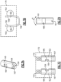
- the shaft 180 extends to a tool housing 170 which receives two grinders 163 which are moving along the edge of the preform 112 which will become the leading or trailing edge.
- a pivot pin 164 there is a pivot pin 164, and the housing 170 is mounted to pivot about the pin 164.
- a handle 162 may be utilized to assist in movement of the grinders 163 along the preform 112.
- Figure 6B is an enlarged view of the tool portion 124.
- the housing 170 is shown to have pivoted about the pivot pin 164, changing the orientation of the two grinders 163.
- FIG 7A shows a detail of the grinders 163.
- notch 167 having the two side edges 126 which will form the edge sides 130.
- slot 165 that will receive a pin to maintain the grinder 163 within the housing 170.
- the sides 126 may be formed of appropriate grinding material given the material forming the preform.
- appropriate grinding material such as carbon boron nitride may be utilized, although other grinding materials may also come within the scope of this disclosure.
- Figure 7B shows a view looking downwardly on the grinders 163.
- the handle 162 has arms 159 in slots 165.
- the grinders 163 are spring biased within the housing 170 by springs 172.
- the arms 159 maintain the grinders 163 within the housing 170, but allow them to move inwardly and outwardly as they move along the edge of the preform 112.
- Figure 7D shows yet another feature of the cutting tool 124. Since the grinder 163 is not restrained within the housing 170 it can also pivot in a direction R, which would generally be into and out of the plane of Figure 7C and generally perpendicularly to rotation about pivot pin 164.
- the grinders 163 are thus able to move along several distinct axes and direction such that they can conform to the needed position for forming complex three-dimensional leading and trailing edges.
- the use of the cam ensures that the cutting tool will be moved in a semi-automated manner and accurately. No complex fully automated machinery is needed.
- a method of forming a component having an airfoil under this disclosure could be said to include the steps of a) molding an airfoil preform such that it has an airfoil extending radially, and between a leading edge and a trailing edge, with at least one of the leading and trailing edges being formed with a mold flash, b) machining away the mold flash, c) moving a cutting tool having at least one grinder a notch along the at least one of the preform leading edge and trailing edge, the notch having side surfaces that will form the at least one of the leading edge and trailing edge on the airfoil preform, and d) moving the cutting tool in conjunction with a cam moving through a cam path to control the position of the at least one grinder along the at least one of leading and trailing edges.
- a machining assembly under this disclosure could be said to include a cam wheel and a cam path, with the cam wheel movable along said cam path.
- a strut system connects the cam wheel to a cutting tool.
- the cutting tool includes at least one grinder having a notch with curved sides of an airfoil edge.
- the at least one grinder is received in a housing, and is pivotable relative to said strut system.
Landscapes
- Engineering & Computer Science (AREA)
- Mechanical Engineering (AREA)
- Chemical & Material Sciences (AREA)
- Materials Engineering (AREA)
- Ceramic Engineering (AREA)
- Inorganic Chemistry (AREA)
- Composite Materials (AREA)
- General Engineering & Computer Science (AREA)
- Structures Of Non-Positive Displacement Pumps (AREA)
Abstract
A method of forming a component (100) having an airfoil (102) includes the steps of a) molding an airfoil preform (112) such that it has an airfoil (102) extending radially, and between a leading edge (103) and a trailing edge (105), with at least one of the leading and trailing edges (103, 105) being formed with a mold flash (114), b) machining away the mold flash (114), c) moving a cutting tool (124) having at least one grinder (164) with a notch (167) along the at least one of the preform leading edge (103) and trailing edge (105), the notch (167) having side surfaces (126) that will form the at least one of the leading edge (103) and trailing edge (105) on the airfoil preform (112) and d) moving the cutting tool (124) in conjunction with a cam moving through a cam path to control the position of the at least one grinder (163) along the at least one of leading and trailing edges (103, 105). A machining assembly (139) is also disclosed.
Description
- This application relates to a method and an apparatus for forming leading and trailing edges on airfoils.
- Gas turbine engines are known, and typically include a compressor section compressing air and delivering it into a combustor. The air is mixed with fuel and ignited in the combustor and products of that combustion pass downstream over turbine rotors driving them to rotate. The turbine rotors in turn rotate compressor rotors and a propulsor rotor such as a fan.
- The compressor and turbine sections typically include a plurality of rotating blades with intermediate static vanes. The blades and vanes all have an airfoil shape. As known, an airfoil extends radially, and axially between a leading and trailing edge.
- Historically airfoils have been cast. More recently it has been proposed to mold airfoil bodies. In particular, ceramic matrix composite materials are being proposed for use in forming airfoils, and in particular, for use in the turbine section.
- When molded, an airfoil typically has a mold flash at each of the leading and trailing edges. Currently the leading and trailing edges are finished manually, which is somewhat unreliable.
- To develop fully automated machinery to form the leading and trailing edges would be expensive.
- In an aspect of the present invention, a method of forming a component having an airfoil includes the steps of a) molding an airfoil preform such that it has an airfoil extending radially, and between a leading edge and a trailing edge, with at least one of the leading and trailing edges being formed with a mold flash, b) machining away the mold flash, c) moving a cutting tool having at least one grinder with a notch along the at least one of the preform leading edge and trailing edge, the notch having side surfaces that will form the at least one of the leading edge and trailing edge on the airfoil preform and d) moving the cutting tool in conjunction with a cam moving through a cam path to control the position of the at least one grinder along the at least one of leading and trailing edges.
- In an embodiment, at least the method steps c) and d) are performed on each of the leading edge and trailing edge.
- In another embodiment according to any of the previous embodiments, steps a)-d) are performed on each of the leading and trailing edges.
- In another embodiment according to any of the previous embodiments, the cutting tool has a pair of grinders moving serially along the at least one of the leading and trailing edges.
- In another embodiment according to any of the previous embodiments, the pair of grinders are mounted within a housing. The housing is pivotally mounted on a strut such that the orientation of the notch in the grinders can change as it moves along a surface of the preform.
- In another embodiment according to any of the previous embodiments, the pair of grinders are movable axially into and out of the housing as they move along the preform.
- In another embodiment according to any of the previous embodiments, the pair of grinders are retained within the housing, but allowed to move axially.
- In another embodiment according to any of the previous embodiments, at least one spring biases the pair of grinders outwardly of the housing.
- In another embodiment according to any of the previous embodiments, an arm is received within a slot in the to retain the pair of grinders within the housing but allow them to move axially.
- In another embodiment according to any of the previous embodiments, the pair of grinders are allowed to rotate in a direction generally perpendicular to a direction of rotation about the pivot pin.
- In another embodiment according to any of the previous embodiments, at least one grinder is mounted within a housing. The housing is pivotally mounted on a strut such that the orientation of the notch in the grinders can change as it moves along a surface of the preform.
- In another embodiment according to any of the previous embodiments, at least one grinder is movable axially into and out of the housing as it moves along the preform.
- In another embodiment according to any of the previous embodiments, at least one grinder is retained within the housing, but allowed to move axially.
- In another embodiment according to any of the previous embodiments, at least one spring biases the at least one grinder outwardly of the housing.
- In another embodiment according to any of the previous embodiments, an arm is received within a slot in the grinder to retain the grinder within the housing but allow it to move axially.
- In another embodiment according to any of the previous embodiments, the grinder is allowed to rotate in a direction generally perpendicular to a direction of rotation about the pivot pin.
- In another embodiment according to any of the previous embodiments, the grinder is allowed to rotate in a direction generally perpendicular to a direction of rotation about the pivot pin.
- In another embodiment according to any of the previous embodiments, the preform is formed of ceramic matrix composites.
- In another embodiment according to any of the previous embodiments, the preform is to be a static vane for use in a gas turbine engine turbine section.
- In another aspect of the present invention, a machining assembly includes a cam wheel and a cam path, with the cam wheel movable along the cam path. A strut system connects the cam wheel to a cutting tool. The cutting tool includes at least one grinder having a notch with curved sides to form an airfoil edge. The at least one grinder is received in a housing, and the housing is pivotable relative to the strut system.
- The present disclosure may include any one or more of the individual features disclosed above and/or below alone or in any combination thereof.
- These and other features of the present invention can be best understood from the following specification and drawings, the following of which is a brief description.
-
-
Figure 1 schematically shows a gas turbine engine. -
Figure 2A shows a component for use in a gas turbine engine ofFigure 1 . -
Figure 2B is another view of theFigure 2A component. -
Figure 3A schematically shows a first step in molding a component. -
Figure 3B shows a subsequent machining step. -
Figure 3C shows another subsequent machining step. -
Figure 3D shows a final machining step. -
Figure 3E shows a detail of an edge of the component after theFigure 3D machining step. -
Figure 4A shows a machine assembly for performing the tooling steps ofFigures 3B and 3C . -
Figure 4B shows a machine assembly for performing theFigure 3D step. -
Figure 5 shows a detail of a cam. -
Figure 6A shows a tool which is part of the machine assembly ofFigure 4B . -
Figure 6B shows a detail of theFigure 6A tool. -
Figure 7A shows a grinder for theFigure 6A tool. -
Figure 7B shows an internal portion of the tool of theFigure 6A tool. -
Figure 7C shows another view of theFigure 6A tool. -
Figure 7D shows the grinder associated with theFigure 6A tool. -
Figure 1 schematically illustrates agas turbine engine 20. Thegas turbine engine 20 is disclosed herein as a two-spool turbofan that generally incorporates afan section 22, acompressor section 24, acombustor section 26 and aturbine section 28. Thefan section 22 may include a single-stage fan 42 having a plurality of fan blades 43. The fan blades 43 may have a fixed stagger angle or may have a variable pitch to direct incoming airflow from an engine inlet. The fan 42 drives air along a bypass flow path B in a bypass duct 13 defined within ahousing 15 such as a fan case or nacelle, and also drives air along a core flow path C for compression and communication into thecombustor section 26 then expansion through theturbine section 28. A splitter 29 aft of the fan 42 divides the air between the bypass flow path B and the core flow path C. Thehousing 15 may surround the fan 42 to establish an outer diameter of the bypass duct 13. The splitter 29 may establish an inner diameter of the bypass duct 13. Although depicted as a two-spool turbofan gas turbine engine in the disclosed non-limiting embodiment, it should be understood that the concepts described herein are not limited to use with two-spool turbofans as the teachings may be applied to other types of turbine engines including three-spool architectures. Theengine 20 may incorporate a variable area nozzle for varying an exit area of the bypass flow path B and/or a thrust reverser for generating reverse thrust. - The
exemplary engine 20 generally includes alow speed spool 30 and ahigh speed spool 32 mounted for rotation about an engine central longitudinal axis A relative to an enginestatic structure 36 viaseveral bearing systems 38. It should be understood that various bearingsystems 38 at various locations may alternatively or additionally be provided, and the location of bearingsystems 38 may be varied as appropriate to the application. - The
low speed spool 30 generally includes aninner shaft 40 that interconnects, a first (or low)pressure compressor 44 and a first (or low)pressure turbine 46. Theinner shaft 40 is connected to the fan 42 through a speed change mechanism, which in the exemplarygas turbine engine 20 is illustrated as a gearedarchitecture 48 to drive the fan 42 at a lower speed than thelow speed spool 30. Theinner shaft 40 may interconnect thelow pressure compressor 44 andlow pressure turbine 46 such that thelow pressure compressor 44 andlow pressure turbine 46 are rotatable at a common speed and in a common direction. In other embodiments, thelow pressure turbine 46 drives both the fan 42 andlow pressure compressor 44 through the gearedarchitecture 48 such that the fan 42 andlow pressure compressor 44 are rotatable at a common speed. Although this application discloses gearedarchitecture 48, its teaching may benefit direct drive engines having no geared architecture. Thehigh speed spool 32 includes anouter shaft 50 that interconnects a second (or high)pressure compressor 52 and a second (or high)pressure turbine 54. Acombustor 56 is arranged in theexemplary gas turbine 20 between thehigh pressure compressor 52 and thehigh pressure turbine 54. Amid-turbine frame 57 of the enginestatic structure 36 may be arranged generally between thehigh pressure turbine 54 and thelow pressure turbine 46. Themid-turbine frame 57 furthersupports bearing systems 38 in theturbine section 28. Theinner shaft 40 and theouter shaft 50 are concentric and rotate via bearingsystems 38 about the engine central longitudinal axis A which is collinear with their longitudinal axes. - Airflow in the core flow path C is compressed by the
low pressure compressor 44 then thehigh pressure compressor 52, mixed and burned with fuel in thecombustor 56, then expanded through thehigh pressure turbine 54 andlow pressure turbine 46. Themid-turbine frame 57 includesairfoils 59 which are in the core flow path C. Theturbines low speed spool 30 andhigh speed spool 32 in response to the expansion. It will be appreciated that each of the positions of thefan section 22,compressor section 24,combustor section 26,turbine section 28, and fandrive gear system 48 may be varied. For example,gear system 48 may be located aft of the low pressure compressor, or aft of thecombustor section 26 or even aft ofturbine section 28, and fan 42 may be positioned forward or aft of the location ofgear system 48. - The fan 42 may have at least 10 fan blades 43 but no more than 20 or 24 fan blades 43. In examples, the fan 42 may have between 12 and 18 fan blades 43, such as 14 fan blades 43. An exemplary fan size measurement is a maximum radius between the tips of the fan blades 43 and the engine central longitudinal axis A. The maximum radius of the fan blades 43 can be at least 40 inches (1.0 m), or more narrowly no more than 75 inches (1.9 m). For example, the maximum radius of the fan blades 43 can be between 45 inches (1.1 m) and 60 inches (1.5 m), such as between 50 inches (1.3 m) and 55 inches (1.4 m). Another exemplary fan size measurement is a hub radius, which is defined as distance between a hub of the fan 42 at a location of the leading edges of the fan blades 43 and the engine central longitudinal axis A. The fan blades 43 may establish a fan hub-to-tip ratio, which is defined as a ratio of the hub radius divided by the maximum radius of the fan 42. The fan hub-to-tip ratio can be less than or equal to 0.35, or more narrowly greater than or equal to 0.20, such as between 0.25 and 0.30. The combination of fan blade counts and fan hub-to-tip ratios disclosed herein can provide the
engine 20 with a relatively compact fan arrangement. - The
low pressure compressor 44,high pressure compressor 52,high pressure turbine 54 andlow pressure turbine 46 each include one or more stages having a row of rotatable airfoils. Each stage may include a row of vanes adjacent the rotatable airfoils. The rotatable airfoils are schematically indicated at 47, and the vanes are schematically indicated at 49. - The
low pressure compressor 44 andlow pressure turbine 46 can include an equal number of stages. For example, theengine 20 can include a three-stagelow pressure compressor 44, an eight-stagehigh pressure compressor 52, a two-stagehigh pressure turbine 54, and a three-stagelow pressure turbine 46 to provide a total of sixteen stages. In other examples, thelow pressure compressor 44 includes a different (e.g., greater) number of stages than thelow pressure turbine 46. For example, theengine 20 can include a five-stagelow pressure compressor 44, a nine-stagehigh pressure compressor 52, a two-stagehigh pressure turbine 54, and a four-stagelow pressure turbine 46 to provide a total of twenty stages. In other embodiments, theengine 20 includes a four-stagelow pressure compressor 44, a nine-stagehigh pressure compressor 52, a two-stagehigh pressure turbine 54, and a three-stagelow pressure turbine 46 to provide a total of eighteen stages. It should be understood that theengine 20 can incorporate other compressor and turbine stage counts, including any combination of stages disclosed herein. - The
engine 20 may be a high-bypass geared aircraft engine. The bypass ratio can be greater than or equal to 10.0 and less than or equal to about 18.0, or more narrowly can be less than or equal to 16.0. The gearedarchitecture 48 may be an epicyclic gear train, such as a planetary gear system or a star gear system. The epicyclic gear train may include a sun gear, a ring gear, a plurality of intermediate gears meshing with the sun gear and ring gear, and a carrier that supports the intermediate gears. The sun gear may provide an input to the gear train. The ring gear (e.g., star gear system) or carrier (e.g., planetary gear system) may provide an output of the gear train to drive the fan 42. A gear reduction ratio may be greater than or equal to 2.3, or more narrowly greater than or equal to 3.0, and in some embodiments the gear reduction ratio is greater than or equal to 3.4. The gear reduction ratio may be less than or equal to 4.0. The fan diameter is significantly larger than that of thelow pressure compressor 44. Thelow pressure turbine 46 can have a pressure ratio that is greater than or equal to 8.0 and in some embodiments is greater than or equal to 10.0. The low pressure turbine pressure ratio can be less than or equal to 13.0, or more narrowly less than or equal to 12.0.Low pressure turbine 46 pressure ratio is pressure measured prior to an inlet oflow pressure turbine 46 as related to the pressure at the outlet of thelow pressure turbine 46 prior to an exhaust nozzle. It should be understood, however, that the above parameters are only exemplary of one embodiment of a geared architecture engine and that the present invention is applicable to other gas turbine engines including direct drive turbofans. All of these parameters are measured at the cruise condition described below. - A significant amount of thrust is provided by the bypass flow B due to the high bypass ratio. The
fan section 22 of theengine 20 is designed for a particular flight condition -- typically cruise at about 0.8 Mach and about 35,000 feet (10,668 meters). The flight condition of 0.8 Mach and 35,000 ft (10,668 meters), with the engine at its best fuel consumption - also known as "bucket cruise Thrust Specific Fuel Consumption ('TSFC')" - is the industry standard parameter of Ibm of fuel being burned divided by Ibf of thrust the engine produces at that minimum point. The engine parameters described above, and those in the next paragraph are measured at this condition unless otherwise specified. - "Fan pressure ratio" is the pressure ratio across the fan blade 43 alone, without a Fan Exit Guide Vane ("FEGV") system. A distance is established in a radial direction between the inner and outer diameters of the bypass duct 13 at an axial position corresponding to a leading edge of the splitter 29 relative to the engine central longitudinal axis A. The fan pressure ratio is a spanwise average of the pressure ratios measured across the fan blade 43 alone over radial positions corresponding to the distance. The fan pressure ratio can be less than or equal to 1.45, or more narrowly greater than or equal to 1.25, such as between 1.30 and 1.40. "Corrected fan tip speed" is the actual fan tip speed in ft/sec divided by an industry standard temperature correction of [(Tram °R) / (518.7 °R)]0.5. The corrected fan tip speed can be less than or equal to 1150.0 ft / second (350.5 meters/second), and can be greater than or equal to 1000.0 ft / second (304.8 meters/second).
- The fan 42,
low pressure compressor 44 andhigh pressure compressor 52 can provide different amounts of compression of the incoming airflow that is delivered downstream to theturbine section 28 and cooperate to establish an overall pressure ratio (OPR). The OPR is a product of the fan pressure ratio across a root (i.e., 0% span) of the fan blade 43 alone, a pressure ratio across thelow pressure compressor 44 and a pressure ratio across thehigh pressure compressor 52. The pressure ratio of thelow pressure compressor 44 is measured as the pressure at the exit of thelow pressure compressor 44 divided by the pressure at the inlet of thelow pressure compressor 44. In examples, a sum of the pressure ratio of thelow pressure compressor 44 and the fan pressure ratio is between 3.0 and 6.0, or more narrowly is between 4.0 and 5.5. The pressure ratio of the highpressure compressor ratio 52 is measured as the pressure at the exit of thehigh pressure compressor 52 divided by the pressure at the inlet of thehigh pressure compressor 52. In examples, the pressure ratio of thehigh pressure compressor 52 is between 9.0 and 12.0, or more narrowly is between 10.0 and 11.5. The OPR can be equal to or greater than 45.0, and can be less than or equal to 70.0, such as between 50.0 and 60.0. The overall and compressor pressure ratios disclosed herein are measured at the cruise condition described above, and can be utilized in two-spool architectures such as theengine 20 as well as three-spool engine architectures. - The
engine 20 establishes a turbine entry temperature (TET). The TET is defined as a maximum temperature of combustion products communicated to an inlet of theturbine section 28 at a maximum takeoff (MTO) condition. The inlet is established at the leading edges of the axially forwardmost row of airfoils of theturbine section 28, and MTO is measured at maximum thrust of theengine 20 at static sea-level and 86 degrees Fahrenheit (°F) (30 °C). The TET may be greater than or equal to 2700.0 °F (1482.2 °C), or more narrowly less than or equal to 3500.0 °F (1926.7 °C), such as between 2750.0 °F (1510.0 °C) and 3350.0 °F (1843.3 °C). The relatively high TET can be utilized in combination with the other techniques disclosed herein to provide a compact turbine arrangement. - The
engine 20 establishes an exhaust gas temperature (EGT). The EGT is defined as a maximum temperature of combustion products in the core flow path C communicated to at the trailing edges of the axially aftmost row of airfoils of theturbine section 28 at the MTO condition. The EGT may be less than or equal to 1000.0 °F (537.8°C), or more narrowly greater than or equal to 800.0 °F (426.7°C), such as between 900.0 °F (482.2°C) and 975.0 °F (523.9°C). The relatively low EGT can be utilized in combination with the other techniques disclosed herein to reduce fuel consumption. -
Figure 2A shows acomponent 100 which is shown as a static vane such as may be utilized in a turbine section for an engine like the engine shown inFigure 1 . While the disclosure here is specific to a static vane, the teachings could apply to rotating blades, and other components having airfoils. As shown, there is anairfoil 102 extending radially between a radially outer platform 106 and a radiallyinner platform 108. The airfoil extends between a trailingedge 105 and aleading edge 103. -
Figure 2B is another view ofcomponent 100. These Figures shows theairfoil 102 in a highly simplified way. In fact the airfoil and edges 103 and 105 have complex curves and shapes. - As mentioned above, historically such components were formed by casting. More recently various materials such as ceramic matrix composites ("CMC") have been proposed particularly for use in the turbine section molding is being used.
- A composite material such as a polymer matrix composite ("PMC"), metal matrix composite ("MMC"), ceramic matrix composite ("CMC"), or a monolithic ceramic may be used. In specific, a CMC material may be comprised of one or more ceramic fiber plies in a ceramic matrix. Example of ceramic matrices are silicon-containing ceramics, such as but not limited to, a silicon carbide (SiC) matrix or a silicon nitride (Si3N4) matrix. Example ceramic reinforcements of the CMC are silicon-containing ceramic fibers, such as but not limited to, silicon carbide (SiC) fiber or silicon nitride (Si3N4) fibers. The CMC may be, but is not limited to, a SiC/SiC ceramic matrix composite in which SiC fiber plies are disposed within a SiC matrix. A fiber ply has a fiber architecture, which refers to an ordered arrangement of the fiber tows/yarns relative to one another, such as a 2D/3D weave, braid, knit, or a nonwoven structure. A monolithic ceramic does not contain fibers or reinforcement and is comprised of a single material. Example monolithic ceramics include silicon-containing ceramics, such as silicon carbide (SiC) or silicon nitride (Si3N4).
- Although a ceramic matrix composite component is specifically disclosed, the teachings of this application could extend to airfoils formed of other materials including metals.
-
Figure 3A shows a challenge when molding a component such ascomponent 100. Amold assembly 110 is schematically shown having mold halves 111. Apreform 112 which will become the airfoil is shown with amold flash 114 extending outwardly beyond an edge which may be either the leading or trailing edge. - Once the
preform 112 is removed from the mold apparatus 110 a first machining step is taken to remove theflash 114. As shown inFigure 3B tool 120 is moving to remove theflash 114. - As shown in
Figure 3C , the flash has now been removed leaving thepreform 112. As shown, the edge 113 is flat at its outermost point. -
Figure 3D shows a subsequent machining step with acutting tool 124 havingside edges 126 which form sides of the leading and trailing edges on thepreform 112. - As shown in
Figure 3E , after the machining ofFigure 3D , theleading edge 103 now has thecurved side portions 130 and aflat portion 132 at its outermost extent. The flat portion is only over a small portion of the edge, and serves to limit the cutting depth of thetool 124. As an example, the flat portion may be only over 0.001 - 0.002 inch (0.025 - 0.051 mm). -
Figure 4A schematically shows amachine assembly 139 for performing theFigures 3B and 3C steps. Acam wheel 142 is attached to a strutsystem having rod 144 that extends outwardly to acrossing tool 140.Rod 140 is attached to atool 120.Tool 120 is a cutting tool such as a carbide cutting tool. The initial cut is made using a standard carbide cutting tool. - As can be appreciated, the
tool 120 may be moved manually along the edge ofpreform 112. Thecam surface 150, as will be explained better below, is designed such that thecutting tool 120 will move as desired along the tip of thepreform 112 to remove the flash. -
Figure 4B shows amachine assembly 137 for the subsequent step ofFigure 3D .Machine assembly 137 has acam wheel 143 attached to a strutsystem having rod 145 which extends to a crossing rod 141. Crossing rod 141 extends to anotherrod 180 and thecutting tool 124 is attached to therod 180. Thecutting tool 124 will be shown to have opposed cuttingedges 126 which will remove the material to form the leading edge such as shown inFigure 3E . - Here again, the
tool 124 will move manually with thewheel 143 moving along a designedcam surface 150 to achieve a desired machining path. Cam surfaces 150 may be different for the twoassemblies -
Figure 5 shows an example of the cam having thewheels 142/143 moving along a path orsurface 150.Surface 150 can be shown to curve between higher points 151 andlower points 153. The shape of this path is selected to achieve desired movement of thecutting tools preform 112. -
Figure 6A shows thecutting tool 124. As shown, theshaft 180 extends to atool housing 170 which receives twogrinders 163 which are moving along the edge of thepreform 112 which will become the leading or trailing edge. As shown, there is apivot pin 164, and thehousing 170 is mounted to pivot about thepin 164. Ahandle 162 may be utilized to assist in movement of thegrinders 163 along thepreform 112. -
Figure 6B is an enlarged view of thetool portion 124. Here thehousing 170 is shown to have pivoted about thepivot pin 164, changing the orientation of the twogrinders 163. -
Figure 7A shows a detail of thegrinders 163. There is anotch 167 having the twoside edges 126 which will form the edge sides 130. There is also aslot 165 that will receive a pin to maintain thegrinder 163 within thehousing 170. - The
sides 126 may be formed of appropriate grinding material given the material forming the preform. As an example, carbon boron nitride may be utilized, although other grinding materials may also come within the scope of this disclosure. -
Figure 7B shows a view looking downwardly on thegrinders 163. Thehandle 162 hasarms 159 inslots 165. - As shown in
Figure 7C thegrinders 163 are spring biased within thehousing 170 bysprings 172. Thearms 159 maintain thegrinders 163 within thehousing 170, but allow them to move inwardly and outwardly as they move along the edge of thepreform 112. -
Figure 7D shows yet another feature of thecutting tool 124. Since thegrinder 163 is not restrained within thehousing 170 it can also pivot in a direction R, which would generally be into and out of the plane ofFigure 7C and generally perpendicularly to rotation aboutpivot pin 164. - The
grinders 163 are thus able to move along several distinct axes and direction such that they can conform to the needed position for forming complex three-dimensional leading and trailing edges. The use of the cam ensures that the cutting tool will be moved in a semi-automated manner and accurately. No complex fully automated machinery is needed. - A method of forming a component having an airfoil under this disclosure could be said to include the steps of a) molding an airfoil preform such that it has an airfoil extending radially, and between a leading edge and a trailing edge, with at least one of the leading and trailing edges being formed with a mold flash, b) machining away the mold flash, c) moving a cutting tool having at least one grinder a notch along the at least one of the preform leading edge and trailing edge, the notch having side surfaces that will form the at least one of the leading edge and trailing edge on the airfoil preform, and d) moving the cutting tool in conjunction with a cam moving through a cam path to control the position of the at least one grinder along the at least one of leading and trailing edges.
- A machining assembly under this disclosure could be said to include a cam wheel and a cam path, with the cam wheel movable along said cam path. A strut system connects the cam wheel to a cutting tool. The cutting tool includes at least one grinder having a notch with curved sides of an airfoil edge. The at least one grinder is received in a housing, and is pivotable relative to said strut system.
- Although embodiments of this disclosure have been disclosed, a worker of ordinary skill in this art would recognize that modifications would come within the scope of this disclosure. For that reason, the following claims should be studied to determine the true scope and content of this disclosure.
Claims (13)
- A method of forming a component (100) having an airfoil (102) comprising:a) molding an airfoil preform (112) such that it has an airfoil (102) extending radially, and between a leading edge (103) and a trailing edge (105), with at least one of the leading and trailing edges (103, 105) being formed with a mold flash (114);b) machining away the mold flash (114);c) moving a cutting tool (124) having at least one grinder (163) with a notch (167) along the at least one of the preform leading edge (103) and trailing edge (105), the notch (167) having side surfaces (126) that will form the at least one of the leading edge (103) and trailing edge (105) on the airfoil preform (112); andd) moving the cutting tool (124) in conjunction with a cam (143) moving through a cam path (150) to control the position of the at least one grinder (163) along the at least one of leading and trailing edges (103, 105).
- The method of claim 1, wherein at least the method steps c) and d) are performed on each of the leading edge (103) and trailing edge (105).
- The method of claim 1, wherein steps a)-d) are performed on each of the leading and trailing edges (103, 105).
- The method of claim 1, 2 or 3, wherein the at least one grinder (163) is mounted within a housing (170), and the housing (170) is pivotally mounted on a pivot pin (164) such that the orientation of the notch (167) in the at least one grinder (163) can change as it moves along a surface of the preform (112).
- The method of claim 4, wherein the at least one grinder (163) is movable axially into and out of the housing (170) as it moves along the preform (112).
- The method of claim 4 or 5, wherein the at least one grinder (163) is retained within the housing (170), but allowed to move axially.
- The method of claim 4, 5 or 6, wherein at least one spring (172) biases the at least one grinder (163) outwardly of the housing (170).
- The method of any of claims 4 to 7, wherein an arm (159) is received within a slot (165) in the at least one grinder (163) to retain the at least one grinder (163) within the housing (170) but allow it to move axially.
- The method of any of claims 4 to 8, wherein the grinder (163) is allowed to rotate in a direction generally perpendicular to a direction of rotation about the pivot pin (164).
- The method as set forth in any preceding claim, wherein the at least one grinder (163) comprises a pair of grinders (163) moving serially along the at least one of the leading and trailing edges (103, 105).
- The method of any preceding claim, wherein the preform (112) is formed of ceramic matrix composites.
- The method of any preceding claim, wherein the preform (112) is to be a static vane for use in a gas turbine engine turbine section.
- A machining assembly (139) comprising:a cam wheel (143) and a cam path (150), with the cam wheel (143) movable along said cam path (150);a strut system (141, 145, 180) connecting the cam wheel (143) to a cutting tool (124), the cutting tool (124) including at least one grinder (163) having a notch (167) with curved sides (126) to form an airfoil edge (103, 105); andthe at least one grinder (163) received in a housing (170), and the housing (170) being pivotable relative to said strut system (141, 145, 180).
Applications Claiming Priority (1)
| Application Number | Priority Date | Filing Date | Title |
|---|---|---|---|
| US18/345,306 US20250001543A1 (en) | 2023-06-30 | 2023-06-30 | Method and apparatus for forming leading and trailing edges on airfoils |
Publications (1)
| Publication Number | Publication Date |
|---|---|
| EP4497532A1 true EP4497532A1 (en) | 2025-01-29 |
Family
ID=91738325
Family Applications (1)
| Application Number | Title | Priority Date | Filing Date |
|---|---|---|---|
| EP24185565.9A Pending EP4497532A1 (en) | 2023-06-30 | 2024-06-28 | Method and apparatus for forming leading and trailing edges on airfoils |
Country Status (2)
| Country | Link |
|---|---|
| US (1) | US20250001543A1 (en) |
| EP (1) | EP4497532A1 (en) |
Citations (7)
| Publication number | Priority date | Publication date | Assignee | Title |
|---|---|---|---|---|
| US2680392A (en) * | 1948-10-08 | 1954-06-08 | Power Jets Res & Dev Ltd | Method and apparatus for making turbine blades |
| US2741164A (en) * | 1951-02-20 | 1956-04-10 | Rolls Royce | Methods of and apparatus for working materials |
| US4015509A (en) * | 1974-10-23 | 1977-04-05 | Trw Inc. | Method and apparatus for shaping an airfoil |
| US5954464A (en) * | 1997-09-05 | 1999-09-21 | United Technologies Corporation | Method for forming the edge of an airfoil |
| US20070234564A1 (en) * | 2006-02-28 | 2007-10-11 | Shafir Aaron R | Method and apparatus for producing blades |
| US20130161297A1 (en) * | 2011-12-22 | 2013-06-27 | Lufthansa Technik Ag | Device for re-contouring a gas turbine blade |
| US20140305270A1 (en) * | 2013-04-11 | 2014-10-16 | Rolls-Royce Plc | Shaping of aerofoil edges |
Family Cites Families (5)
| Publication number | Priority date | Publication date | Assignee | Title |
|---|---|---|---|---|
| US2482375A (en) * | 1944-11-22 | 1949-09-20 | Sensenich Corp | Process of manufacturing plastic coated wood propellers or impellers |
| US5110652A (en) * | 1989-12-04 | 1992-05-05 | Corning Incorporated | Shaped fiber-reinforced ceramic composite article |
| US7097540B1 (en) * | 2005-05-26 | 2006-08-29 | General Electric Company | Methods and apparatus for machining formed parts to obtain a desired profile |
| US8127442B2 (en) * | 2005-12-15 | 2012-03-06 | United Technologies Corporation | Compressor blade flow form technique for repair |
| US9802288B2 (en) * | 2014-06-16 | 2017-10-31 | United Technologies Corporation | Machining system having a tool for finishing airfoils |
-
2023
- 2023-06-30 US US18/345,306 patent/US20250001543A1/en active Pending
-
2024
- 2024-06-28 EP EP24185565.9A patent/EP4497532A1/en active Pending
Patent Citations (7)
| Publication number | Priority date | Publication date | Assignee | Title |
|---|---|---|---|---|
| US2680392A (en) * | 1948-10-08 | 1954-06-08 | Power Jets Res & Dev Ltd | Method and apparatus for making turbine blades |
| US2741164A (en) * | 1951-02-20 | 1956-04-10 | Rolls Royce | Methods of and apparatus for working materials |
| US4015509A (en) * | 1974-10-23 | 1977-04-05 | Trw Inc. | Method and apparatus for shaping an airfoil |
| US5954464A (en) * | 1997-09-05 | 1999-09-21 | United Technologies Corporation | Method for forming the edge of an airfoil |
| US20070234564A1 (en) * | 2006-02-28 | 2007-10-11 | Shafir Aaron R | Method and apparatus for producing blades |
| US20130161297A1 (en) * | 2011-12-22 | 2013-06-27 | Lufthansa Technik Ag | Device for re-contouring a gas turbine blade |
| US20140305270A1 (en) * | 2013-04-11 | 2014-10-16 | Rolls-Royce Plc | Shaping of aerofoil edges |
Also Published As
| Publication number | Publication date |
|---|---|
| US20250001543A1 (en) | 2025-01-02 |
Similar Documents
| Publication | Publication Date | Title |
|---|---|---|
| EP3027853B1 (en) | Gas turbine engine cmc airfoil assembly | |
| EP2961938B1 (en) | Gas turbine engine composite airfoil and method | |
| EP2981676B1 (en) | Engine component having support with intermediate layer | |
| US20230055197A1 (en) | Attachment region for cmc components | |
| WO2015126454A1 (en) | Gas turbine engine airfoil | |
| EP4190557A1 (en) | Machining of ceramic matrix composite during preforming and partial densification | |
| EP4603679A1 (en) | Blade outer air seal with machinable coating at sealing surfaces | |
| EP4379190B1 (en) | Removable layer to adjust mount structure of a turbine vane for re-stagger | |
| US20250001543A1 (en) | Method and apparatus for forming leading and trailing edges on airfoils | |
| EP4379187A1 (en) | Gas turbine engine component having an airfoil with internal cross-ribs | |
| EP4353949B1 (en) | Gas turbine engine vane and spar combination with variable air flow path | |
| EP3108117B2 (en) | Gas turbine engine airfoil | |
| US20250243767A1 (en) | Method of forming load bearing insert and insert for ceramic matrix composite turbine components | |
| EP4603246A1 (en) | Multi-piece mandrel for building up airfoil structure | |
| EP4603245A1 (en) | Forming gas turbine engine airfoils from cmcs with a kickback to facilitate mandrel removal | |
| US12448897B2 (en) | Gas turbine engine component formed by CMCS and having a compressed insert with tapered ends | |
| EP4417788A1 (en) | Gas turbine engine blade and method of sizing a damper for a gas turbine engine blade | |
| EP4603247A1 (en) | Extended inner profile for mandrel for use in forming braided cmc structures | |
| US20260139600A1 (en) | Machinable coating for damping | |
| US12428965B2 (en) | Load bearing feature for ceramic matrix composite turbine components | |
| EP4549701B1 (en) | Combined gas turbine engine vane and blade outer air seal assembly and gas turbine engine | |
| EP4379188B1 (en) | Gas turbine engine static vane clusters | |
| EP4372207B1 (en) | Blade outer air seal with large radius of curvature mount hooks |
Legal Events
| Date | Code | Title | Description |
|---|---|---|---|
| PUAI | Public reference made under article 153(3) epc to a published international application that has entered the european phase |
Free format text: ORIGINAL CODE: 0009012 |
|
| STAA | Information on the status of an ep patent application or granted ep patent |
Free format text: STATUS: THE APPLICATION HAS BEEN PUBLISHED |
|
| AK | Designated contracting states |
Kind code of ref document: A1 Designated state(s): AL AT BE BG CH CY CZ DE DK EE ES FI FR GB GR HR HU IE IS IT LI LT LU LV MC ME MK MT NL NO PL PT RO RS SE SI SK SM TR |
|
| STAA | Information on the status of an ep patent application or granted ep patent |
Free format text: STATUS: REQUEST FOR EXAMINATION WAS MADE |
|
| 17P | Request for examination filed |
Effective date: 20250729 |