EP4497493A1 - Fluid recovery system and fluid recovery method using same - Google Patents
Fluid recovery system and fluid recovery method using same Download PDFInfo
- Publication number
- EP4497493A1 EP4497493A1 EP23775139.1A EP23775139A EP4497493A1 EP 4497493 A1 EP4497493 A1 EP 4497493A1 EP 23775139 A EP23775139 A EP 23775139A EP 4497493 A1 EP4497493 A1 EP 4497493A1
- Authority
- EP
- European Patent Office
- Prior art keywords
- fluid
- flow path
- filter member
- unit
- communication unit
- Prior art date
- Legal status (The legal status is an assumption and is not a legal conclusion. Google has not performed a legal analysis and makes no representation as to the accuracy of the status listed.)
- Pending
Links
Images




Classifications
-
- B—PERFORMING OPERATIONS; TRANSPORTING
- B01—PHYSICAL OR CHEMICAL PROCESSES OR APPARATUS IN GENERAL
- B01D—SEPARATION
- B01D53/00—Separation of gases or vapours; Recovering vapours of volatile solvents from gases; Chemical or biological purification of waste gases, e.g. engine exhaust gases, smoke, fumes, flue gases, aerosols
- B01D53/22—Separation of gases or vapours; Recovering vapours of volatile solvents from gases; Chemical or biological purification of waste gases, e.g. engine exhaust gases, smoke, fumes, flue gases, aerosols by diffusion
- B01D53/225—Multiple stage diffusion
- B01D53/226—Multiple stage diffusion in serial connexion
-
- B—PERFORMING OPERATIONS; TRANSPORTING
- B01—PHYSICAL OR CHEMICAL PROCESSES OR APPARATUS IN GENERAL
- B01D—SEPARATION
- B01D53/00—Separation of gases or vapours; Recovering vapours of volatile solvents from gases; Chemical or biological purification of waste gases, e.g. engine exhaust gases, smoke, fumes, flue gases, aerosols
- B01D53/22—Separation of gases or vapours; Recovering vapours of volatile solvents from gases; Chemical or biological purification of waste gases, e.g. engine exhaust gases, smoke, fumes, flue gases, aerosols by diffusion
- B01D53/225—Multiple stage diffusion
-
- B—PERFORMING OPERATIONS; TRANSPORTING
- B01—PHYSICAL OR CHEMICAL PROCESSES OR APPARATUS IN GENERAL
- B01D—SEPARATION
- B01D53/00—Separation of gases or vapours; Recovering vapours of volatile solvents from gases; Chemical or biological purification of waste gases, e.g. engine exhaust gases, smoke, fumes, flue gases, aerosols
- B01D53/22—Separation of gases or vapours; Recovering vapours of volatile solvents from gases; Chemical or biological purification of waste gases, e.g. engine exhaust gases, smoke, fumes, flue gases, aerosols by diffusion
- B01D53/229—Integrated processes (Diffusion and at least one other process, e.g. adsorption, absorption)
-
- B—PERFORMING OPERATIONS; TRANSPORTING
- B01—PHYSICAL OR CHEMICAL PROCESSES OR APPARATUS IN GENERAL
- B01D—SEPARATION
- B01D53/00—Separation of gases or vapours; Recovering vapours of volatile solvents from gases; Chemical or biological purification of waste gases, e.g. engine exhaust gases, smoke, fumes, flue gases, aerosols
- B01D53/002—Separation of gases or vapours; Recovering vapours of volatile solvents from gases; Chemical or biological purification of waste gases, e.g. engine exhaust gases, smoke, fumes, flue gases, aerosols by condensation
-
- B—PERFORMING OPERATIONS; TRANSPORTING
- B01—PHYSICAL OR CHEMICAL PROCESSES OR APPARATUS IN GENERAL
- B01D—SEPARATION
- B01D53/00—Separation of gases or vapours; Recovering vapours of volatile solvents from gases; Chemical or biological purification of waste gases, e.g. engine exhaust gases, smoke, fumes, flue gases, aerosols
- B01D53/22—Separation of gases or vapours; Recovering vapours of volatile solvents from gases; Chemical or biological purification of waste gases, e.g. engine exhaust gases, smoke, fumes, flue gases, aerosols by diffusion
- B01D53/228—Separation of gases or vapours; Recovering vapours of volatile solvents from gases; Chemical or biological purification of waste gases, e.g. engine exhaust gases, smoke, fumes, flue gases, aerosols by diffusion characterised by specific membranes
-
- B—PERFORMING OPERATIONS; TRANSPORTING
- B01—PHYSICAL OR CHEMICAL PROCESSES OR APPARATUS IN GENERAL
- B01D—SEPARATION
- B01D61/00—Processes of separation using semi-permeable membranes, e.g. dialysis, osmosis or ultrafiltration; Apparatus, accessories or auxiliary operations specially adapted therefor
- B01D61/58—Multistep processes
-
- B—PERFORMING OPERATIONS; TRANSPORTING
- B01—PHYSICAL OR CHEMICAL PROCESSES OR APPARATUS IN GENERAL
- B01D—SEPARATION
- B01D53/00—Separation of gases or vapours; Recovering vapours of volatile solvents from gases; Chemical or biological purification of waste gases, e.g. engine exhaust gases, smoke, fumes, flue gases, aerosols
- B01D53/22—Separation of gases or vapours; Recovering vapours of volatile solvents from gases; Chemical or biological purification of waste gases, e.g. engine exhaust gases, smoke, fumes, flue gases, aerosols by diffusion
- B01D2053/221—Devices
- B01D2053/223—Devices with hollow tubes
- B01D2053/224—Devices with hollow tubes with hollow fibres
-
- B—PERFORMING OPERATIONS; TRANSPORTING
- B01—PHYSICAL OR CHEMICAL PROCESSES OR APPARATUS IN GENERAL
- B01D—SEPARATION
- B01D2256/00—Main component in the product gas stream after treatment
- B01D2256/10—Nitrogen
-
- B—PERFORMING OPERATIONS; TRANSPORTING
- B01—PHYSICAL OR CHEMICAL PROCESSES OR APPARATUS IN GENERAL
- B01D—SEPARATION
- B01D2256/00—Main component in the product gas stream after treatment
- B01D2256/12—Oxygen
-
- B—PERFORMING OPERATIONS; TRANSPORTING
- B01—PHYSICAL OR CHEMICAL PROCESSES OR APPARATUS IN GENERAL
- B01D—SEPARATION
- B01D2256/00—Main component in the product gas stream after treatment
- B01D2256/22—Carbon dioxide
-
- B—PERFORMING OPERATIONS; TRANSPORTING
- B01—PHYSICAL OR CHEMICAL PROCESSES OR APPARATUS IN GENERAL
- B01D—SEPARATION
- B01D2257/00—Components to be removed
- B01D2257/10—Single element gases other than halogens
- B01D2257/102—Nitrogen
-
- B—PERFORMING OPERATIONS; TRANSPORTING
- B01—PHYSICAL OR CHEMICAL PROCESSES OR APPARATUS IN GENERAL
- B01D—SEPARATION
- B01D2257/00—Components to be removed
- B01D2257/10—Single element gases other than halogens
- B01D2257/104—Oxygen
-
- B—PERFORMING OPERATIONS; TRANSPORTING
- B01—PHYSICAL OR CHEMICAL PROCESSES OR APPARATUS IN GENERAL
- B01D—SEPARATION
- B01D2257/00—Components to be removed
- B01D2257/50—Carbon oxides
- B01D2257/504—Carbon dioxide
-
- B—PERFORMING OPERATIONS; TRANSPORTING
- B01—PHYSICAL OR CHEMICAL PROCESSES OR APPARATUS IN GENERAL
- B01D—SEPARATION
- B01D2259/00—Type of treatment
- B01D2259/45—Gas separation or purification devices adapted for specific applications
-
- B—PERFORMING OPERATIONS; TRANSPORTING
- B01—PHYSICAL OR CHEMICAL PROCESSES OR APPARATUS IN GENERAL
- B01D—SEPARATION
- B01D2317/00—Membrane module arrangements within a plant or an apparatus
- B01D2317/02—Elements in series
- B01D2317/025—Permeate series
-
- B—PERFORMING OPERATIONS; TRANSPORTING
- B01—PHYSICAL OR CHEMICAL PROCESSES OR APPARATUS IN GENERAL
- B01D—SEPARATION
- B01D63/00—Apparatus in general for separation processes using semi-permeable membranes
- B01D63/02—Hollow fibre modules
Definitions
- the present invention relates to a fluid recovery system and a fluid recovery method using the same, and more specifically to a fluid recovery system that can effectively separate and recover only a specific fluid from a mixture containing a plurality of fluids, and a fluid recovery method using the same.
- a gas insulated switchgear is a safety device installed in high-voltage power systems such as power plants or substations.
- the gas insulated switchgear performs the switching of load current under normal operating conditions.
- the gas insulated switchgear is provided to protect the power system, by opening and closing the line even in abnormal conditions such as fault current or short-circuit current.
- the gas insulated switchgear is provided with an insulating gas.
- the insulating gas is provided in the gas insulated switchgear and performs an insulating function, thereby improving the operational reliability of the gas insulated switchgear.
- Sulfur hexafluoride As an insulating gas. Sulfur hexafluoride can be produced at low cost, has excellent insulation properties, has a high extinguishing ability of generated arcs, and has a fast insulation recovery rate, and thus, it is widely used as an insulating gas.
- sulfur hexafluoride corresponds to a greenhouse gas that causes global warming.
- a consensus has been formed on reducing greenhouse gases, especially in developed countries, and research is being conducted to develop an insulating gas that can replace sulfur hexafluoride.
- NOVEC 1230 (C 6 F 12 O) developed by 3M has been developed and is being used to replace sulfur hexafluoride.
- the insulating gases developed to date require excessive costs to secure insulating performance equivalent to that of sulfur hexafluoride.
- the insulating gas also has the character of a consumer product.
- the insulating gas must be periodically replaced and recharged. Accordingly, expensive insulating gas must be continuously supplied to the gas insulated switchgear, which places a great burden on the operator of the power system and the consumers receiving power.
- Korean Registered Patent No 10-1086311 discloses a gas filter device for a sulfur hexafluoride gas insulated switchgear. Specifically, it discloses a gas filter device having a structure that is capable of removing dust included in recovered sulfur hexafluoride gas and then reintroducing the same.
- the gas filter device of the sulfur hexafluoride gas insulated switchgear disclosed in the above related art document presupposes that sulfur hexafluoride is still used as an insulating gas.
- the above related art document does not present a plan for a material to be utilized as an insulating gas in place of sulfur hexafluoride.
- PCT Publication No. 2015-102229 discloses a treatment method for sulfur hexafluoride using radiation and a by-product recovery and treatment device. Specifically, it discloses a processing method and processing device for decomposing and recovering sulfur hexafluoride and hydrogen into hydrogen fluoride and sulfur by irradiating a mixed gas of sulfur hexafluoride and hydrogen with radiation.
- the processing method and processing device disclosed in the above related art document only disclose a method for removing sulfur hexafluoride on the premise that it is used as an insulating gas.
- the related art document does not present a method for recovering an insulating gas composed of materials other than sulfur hexafluoride.
- the present invention has been devised to solve the above problems, and an object of the present invention is to provide a fluid recovery system that can efficiently separate a fluid to be recovered from a mixed fluid and a fluid recovery method using the same.
- Another object of the present invention is to provide a fluid recovery system in which the fluid to be recovered can undergo a separation process for multiple times and a fluid recovery method using the same.
- Still another object of the present invention is to provide a fluid recovery system that can improve the separation efficiency of the fluid to be recovered, and a fluid recovery method using the same.
- Still another object of the present invention is to provide a fluid recovery system that can efficiently collect and recover fluid to be recovered, and a fluid recovery method using the same.
- Still another object of the present invention is to provide a fluid recovery system in which the remaining fluid to be recovered can undergo a separation process again, and a fluid recovery method using the same.
- a fluid recovery system including a communication unit which communicates with the outside and introduces a mixed fluid; and a fluid separation unit which is configured to communicate with the communication unit and separate the introduced mixed fluid into at least two different fluids, wherein the fluid separation unit includes a filter member which is configured to communicate with the communication unit, receive the introduced mixed fluid, and separate the received mixed fluid into the at least two different fluids; and a collecting member which is configured to communicate with the filter member and collect a part of any one fluid of the separated fluids, wherein the communication unit includes a collecting communication unit which is configured to communicate with the outside and discharge the part of the any one fluid of the separated fluids; and an exhaust communication unit which is configured to communicate with the outside and discharge the other fluids from among the separated fluids, wherein the part of the any one fluid and the other fluids may be in different phases.
- a plurality of filter members may be provided, and the plurality of filter members may be configured to communicate with each other, and the introduced mixed fluid may pass through at least any one of the plurality of filter members and may be configured to be separated into at least two different fluids.
- the filter member may include a first filter member which communicates with the communication unit, and into which the mixed fluid is introduced; a second filter member which communicates with the first filter member and is located on the downstream side of the first filter member; and a third filter member which communicates with the second filter member and is located on the downstream side of the second filter member.
- the fluid separation unit may include a branch flow path which is coupled to each of the first filter member, the second filter member and the third filter member, and communicates the first filter member, the second filter member and the third filter member with each other; and a branch valve which is provided in the branch flow path and is configured to allow or block the communication of at least any two of the first filter member, the second filter member and the third filter member.
- a plurality of branch flow paths may be provided, and each of the plurality of branch flow paths may be configured to communicate a different pair of filter members among the first filter member, the second filter member and the third filter member with the communication unit, and a plurality of branch valves may be provided, and the plurality of branch valves may be respectively positioned in the plurality of branch flow paths, and may be configured to open or close at least any one branch flow path among the plurality of branch flow paths.
- the filter member may be formed to extend in one direction and is provided with a membrane filter including a plurality of hollow fibers, the any one fluid may flow in the one direction, be separated from the mixed fluid, pass through the filter member, and flow into the collecting communication unit, and the other fluids may flow in the other direction, pass through the hollow fiber, be separated from the mixed fluid, and flow into the exhaust communication unit.
- the other fluids may be composed of a mixture of different fluids
- a plurality of filter members may be provided, and the shape of the hollow fibers provided by each of the plurality of filter members may be formed to be different from each other, and the plurality of filter members may be configured to filter different fluids among the plurality of fluids mixed with the other fluids.
- the area of a membrane provided in the membrane filter may be determined in proportion to the flow rate of the introduced mixed fluid.
- the fluid recovery system may further include a condition control unit which is connected to the fluid separation unit and is configured to heat or cool the filter member or the collecting member.
- condition control unit may include a heating member which is connected to the filter member and is configured to heat the filter member; and a cooling member which is connected to the collecting member and is configured to cool the collecting member.
- the fluid recovery system may further include a flow path unit which is respectively coupled to the communication unit and the fluid separation unit, and communicates the communication unit and the fluid separation unit, wherein the flow path unit includes a collecting flow path unit which is respectively coupled to the filter member and the collecting member, and through which part of the any one fluid that has passed through the filter member flows by communicating the filter member and the collecting member.
- the flow path unit may include a flow path heat-dissipation member which is provided in the collecting flow path unit and is configured to cool the any one fluid flowing therethrough.
- the communication unit may include an inlet communication unit which communicates with the outside to receive the mixed fluid; and an outlet communication unit which communicates with the outside to transfer the remainder of the any one fluid, wherein the fluid recovery system further includes a fluid recovery unit which is respectively connected to the inlet communication unit and the outlet communication unit, and transfers the remainder of the any one fluid to the inlet communication unit.
- a method for recovering a fluid including the steps of (a) receiving a mixed fluid by a fluid separation unit; (b) separating the received mixed fluid into at least two different fluids by the fluid separation unit; (c) collecting a part of any one fluid of the separated at least two different fluids; and d) discharging the remainder of any one fluid of the separated at least two different fluids and the other fluids.
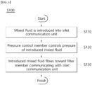
- step (a) may include step (a1) in which the mixed fluid is introduced into the inlet communication unit; step (a2) in which a pressure control member controls the pressure of the introduced mixed fluid; and step (a3) in which the introduced mixed fluid flows toward a filter member that communicates with the inlet communication unit.
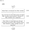
- step (b) may include (b1) introducing the mixed fluid into a filter member; (b2) separating the any one fluid of the mixed fluid while passing through the filter member along the extension direction of the filter member; and (b3) separating the other fluids among the mixed fluid while passing through a membrane provided in the filter member along the other direction of the filter member.
- step (c) may include step (c1) in which the any one fluid of the fluids separated from the mixed fluid is introduced into a collecting member; step (c2) in which a part of the any one fluid is liquefied and collected in the collecting member; and step (c3) in which the part of the collected any one fluid flows in a collecting flow path unit, and is discharged to the outside through a collecting communication unit.
- step (d) may include step (d1) in which the other fluids that have been separated from the mixed fluid flows in an exhaust flow path unit, and is discharged to the outside through an exhaust communication unit; and step (d2) in which the remainder of any one fluid flows in a discharge flow path unit, and is discharged to the outside through a discharge communication unit.
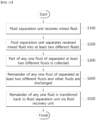
- the fluid recovery method may further include, after step (d), (e) transferring the remainder of the any one fluid back to the fluid separation unit through a fluid recovery unit, wherein step (e) includes step (e1) in which the remainder of the any one fluid is introduced into a recovery flow path unit through a discharge communication unit; step (e2) in which a recovery compressor controls the pressure of the remainder of the introduced any one fluid; and step (e3) in which the remainder of the introduced any one fluid is transferred to the fluid separation unit.
- the fluid recovery system according to an exemplary embodiment of the present invention and the fluid recovery method using the same can efficiently separate a fluid to be recovered from a mixed fluid.
- the fluid recovery system is provided with an inlet communication unit which communicates with the outside.
- the inlet communication unit communicates with a fluid separation unit through an inlet flow path unit.
- the introduced mixed fluid may be transferred to a fluid separation unit.
- the fluid separation unit includes a filter member.
- the filter member may include a membrane to separate the mixed fluid into at least two different fluids.
- the fluid to be recovered flows along the longitudinal direction of the filter member and can be discharged or recovered. Except for the fluid to be recovered, the remaining fluids may be discharged while passing through a membrane in another direction of the filter member, for example, in the radial direction.
- the fluid recovery system according to an exemplary embodiment of the present invention and the fluid recovery method using the same may allow the fluid to be recovered to undergo a separation process for multiple times.
- a plurality of filter members may be provided.
- the plurality of filter members are coupled and communicated with each other, and thus, the mixed fluid transferred to the fluid separation unit may pass through at least one filter member and undergo a separation process.
- the plurality of filter members are respectively coupled to and communicate with a plurality of branch flow paths.
- a plurality of branch valves are provided on each of the plurality of branch flow paths, and the plurality of branch flow paths are controlled to open or close independently of each other.
- the plurality of branch valves are controlled to correspond to each other such that different flow paths through which the mixed fluid can flow may be formed.
- the mixed fluid passes through the filter member at least once and undergoes a separation process.
- the fluid recovery system according to an exemplary embodiment of the present invention and the fluid recovery method using the same can improve the separation efficiency of the fluid to be recovered.
- the filter member is connected to a heating member.
- the heating member is configured to heat the filter member and the mixed fluid flowing therein. Accordingly, the mixed fluid is maintained in a gas phase, and the separation efficiency can be improved.
- the fluid recovery system according to an exemplary embodiment of the present invention and the fluid recovery method using the same can efficiently collect and recover the fluid to be recovered.
- the fluid to be recovered that has passed through the filter member flows to the collecting member.
- the collecting member is configured to phase change and collect the fluid to be recovered. Accordingly, the fluid to be recovered is collected by changing its phase into a liquid phase that is relatively easy to collect and recover.
- a cooling member is connected to the collecting member.
- the cooling member is configured to cool the collecting member and the fluid to be recovered flowing into the collecting member. Accordingly, the fluid to be recovered can be phase changed and maintained in a liquid phase, thereby improving collection and recovery efficiency.
- the fluid recovery system according to an exemplary embodiment of the present invention and the fluid recovery method using the same allow the remaining fluids to be recovered to undergo a separation process again.
- a fluid recovery unit may be provided.
- the fluid recovery unit is coupled to and communicates with the inlet communication unit and the outlet communication unit, respectively.
- the remaining fluids that have not yet changed phase or been collected in the collecting member may be transferred back to the fluid separation unit through the fluid recovery unit and undergo a separation process again.
- the separation process can be repeated, and the efficiency of separation and recovery of the fluid to be recovered can be improved.
- communication means that one or more members are connected to each other in fluid communication.
- the communication channel may be formed by a member such as a conduit, pipe or piping.
- electrical conduction means that one or more members are connected to each other to transmit current or electrical signals.
- electrical conduction may be formed in a wired form using a conductor member, or in a wireless form such as Bluetooth, Wi-Fi or RFID.
- fluid refers to a substance in any state whose shape can be changed by external pressure or temperature.
- the fluid may be in the form of liquid or gas.
- mixed fluid refers to any one fluid that is supplied to the fluid recovery systems 10, 20 and subjected to a separation process.
- the mixed fluid may be composed of a fluid discharged from an external device, such as a gas insulated switchgear.
- any one fluid used in the following description refers to the fluid that is subject to collection and recovery.
- any one fluid may refer to an insulating gas.
- any one fluid may be C 4 F 7 N or C 5 F 10 O.
- other fluids refer to fluids other than the any one fluid subject to collection and recovery.
- the other fluids may refer to fluids other than the insulating gas, such as oxygen or hydrogen.
- the fluid recovery systems 10, 20 may receive a mixed fluid from an external device and separate the same into a plurality of fluids.
- the plurality of separated fluids may be discharged to the outside through different paths.
- any one fluid mixed in the mixed fluid may be separated from the other fluids and supplied again to the external device. Accordingly, the recovery efficiency of any one fluid mixed in the mixed fluid can be increased, and the amount of any one fluid that must be newly provided to be supplied to an external device can be reduced.
- the financial cost required to operate the external device can be reduced. Additionally, as the recovery efficiency of any one fluid is improved, the amount of any one newly provided fluid is also reduced, thereby preventing environmental pollution.
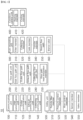
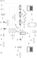
- FIGS. 1 to 2 the configuration of a fluid recovery system 10 according to an exemplary embodiment of the present invention is illustrated.
- Each component of the fluid recovery system 10 described below is in communication with each other such that any one fluid can flow therein.
- power and control signals required to operate each component of the fluid recovery system 10 may be transmitted from an external power source (not illustrated) or a control module (not illustrated).
- Each component of the fluid recovery system 10 is connected to an external power source (not illustrated) and a control module (not illustrated).
- the fluid recovery system 10 includes a communication unit 100, a flow path unit 200, a fluid separation unit 300, a condition control unit 400, and a utility unit 500.
- the communication unit 100 is a component through which the fluid recovery system 10 communicates with the outside.
- the mixed fluid collected from the external device may be supplied to the fluid recovery system 10 through the communication unit 100. Additionally, various fluids that pass through the fluid recovery system 10 and are separated from the mixed fluid may be discharged or recovered to the outside through the communication unit 100.
- the communication unit 100 is coupled to and communicates with the flow path unit 200.
- the communication unit 100 may be combined with and communicate with other components through the flow path unit 200.
- the communication unit 100 is coupled to and communicates with the fluid separation unit 300 by the flow path unit 200.
- a plurality of communication units 100 may be provided.
- a mixed fluid may be transferred from the outside to at least any one of the plurality of communication units 100.
- each fluid separated from the mixed fluid may be discharged to the outside and collected.
- the communication unit 100 includes an inlet communication unit 110, an outlet communication unit 120, an exhaust communication unit 130 and a collecting communication unit 140.
- the inlet communication unit 110 is a passage through which the mixed fluid recovered from an external device flows.
- the inlet communication unit 110 communicates with the flow path unit 200 and the fluid separation unit 300 to the outside.
- the inlet communication unit 110 may be provided to be open and closed. That is, the outer left part of the inlet communication unit 110 in the exemplary embodiment illustrated in FIG. 2 can be opened only when the mixed fluid flows in. In other words, the left part of the inlet communication 110 may be closed while the fluid recovery system 10 is operating.
- the inlet communication unit 110 is coupled to and communicates with the flow path unit 200. Specifically, the inlet communication unit 110 is coupled to and communicates with an inlet flow path unit 210. The mixed fluid flowing in through the inlet communication unit 110 may flow into the fluid separation unit 300 through the inlet flow path unit 210.
- the outlet communication unit 120 is a passage through which any remaining fluid is discharged and recovered to the outside after passing through the fluid separation unit 300. That is, the outlet communication unit 120 functions as a passage for the remainder of any remaining fluid that has not yet been separated from the mixed fluid to be discharged and recovered to the outside.
- the outlet communication unit 120 communicates with the flow path unit 200 and the fluid separation unit 300 to the outside.
- the outlet communication unit 120 may be provided to be open and closed. That is, the outer side of the outlet communication unit 120, which is the left part in the illustrated exemplary embodiment, may be opened only when the remainder of any one fluid is discharged after the separation process of the mixed fluid is performed. In other words, the left part of the outlet communication 120 can be closed while the fluid recovery system 10 is operating.
- the outlet communication unit 120 is coupled to and communicates with the flow path unit 200. Specifically, the outlet communication unit 120 is coupled to and communicates with an outlet flow path unit 220. Through the outlet communication unit 120, the remaining fluid that has undergone the separation process (i.e., the remainder of any one fluid) may be discharged to the outside through the outlet flow path unit 220.
- the exhaust communication unit 130 is a passage through which the fluid that is not subject to recovery among the mixed fluid, that is, the other fluid, is discharged to the outside.
- the exhaust communication unit 130 communicates with the flow path unit 200 and the fluid separation unit 300 to the outside.
- the exhaust communication unit 130 may be provided to be open and closed. That is, the outer side of the exhaust communication unit 130, which is the left part in the illustrated exemplary embodiment, may be opened only when the other fluids that have been separated from the fluid separation unit 300 are discharged. In other words, the exhaust communication unit 130 may be opened only while the fluid recovery system 10 is operating.
- the exhaust communication unit 130 is coupled to and communicates with the flow path unit 200. Specifically, the exhaust communication unit 130 is coupled to and communicates with the filter member 310 of the fluid separation unit 300 through an exhaust flow path unit 230. Through the exhaust communication unit 130, the other fluids that have been separated from the mixed fluid may be discharged to the outside through the exhaust flow path unit 230.
- a plurality of exhaust communication units 130 may be provided.
- the plurality of exhaust communication units 130 may be respectively coupled to and communicate with a plurality of filter members 310 through a plurality of exhaust flow path units 230.
- three exhaust communication units 130 are provided, including a first exhaust communication unit 131, a second exhaust communication unit 132 and a third exhaust communication unit 133.
- the first exhaust communication unit 131 is coupled to and communicates with a first exhaust flow path unit 231 so as to communicate with a first filter member 311.
- the second exhaust communication unit 132 is coupled to and communicates with a second exhaust flow path unit 232 so as to communicate with a second filter member 312.
- the third exhaust communication unit 133 is coupled to and communicates with a third exhaust flow path unit 233 so as to communicate with a third filter member 313.
- the collecting communication unit 140 is a passage through which any one fluid to be recovered among the mixed fluid undergoes a phase change and is discharged to the outside.
- the collecting communication unit 140 communicates with the flow path unit 200 and the fluid separation unit 300 to the outside.
- the collecting communication unit 140 may be provided to be open and closed. That is, the outer side of the collecting communication unit 140, which is the left part in the illustrated exemplary embodiment, may be opened only when any one fluid separated from the fluid separation unit 300 undergoes a phase change and is discharged. In other words, the collecting communication unit 140 may be opened only while the fluid recovery system 10 is operating.
- the collecting communication unit 140 is coupled to and communicates with the flow path unit 200. Specifically, the collecting communication unit 140 is coupled to and communicates with a collecting flow path unit 240. Any one fluid that is collected and phase-changed while passing through a filter member 310, a collecting member 320, a tank member 330 and a transfer member 340 of the fluid separation unit 300 through the collecting communication unit 140 may be discharged to the outside through the collecting flow path unit 240.
- Each component of the communication unit 100 communicates with the fluid separation unit 300 through the flow path unit 200.
- the flow path unit 200 connects each component of the fluid recovery system 10 to enable fluid communication.
- the flow path unit 200 is respectively coupled to each component of the fluid recovery system 10.
- the flow path unit 200 may be formed of a material that is not damaged by the mixed fluid, any one fluid separated from the mixed fluid or other fluids, or does not have a physical or chemical effect on these fluids.
- the flow path unit 200 may be formed of stainless steel (SUS).
- a utility unit 500 may be provided on the flow path unit 200.
- the utility unit 500 may detect the physical properties of a mixed fluid, a separated any one fluid or the other fluids flowing in the flow path unit 200 and control the flow of each fluid. That is, the flow path unit 200 may be controlled by the utility unit 500 to allow or block communication between each component of the fluid recovery system 10.
- a plurality of flow path units 200 may be provided.
- the plurality of flow path units 200 may be respectively combined with different components provided in the fluid recovery system 10 to communicate with the different components.
- the flow path unit 200 includes an inlet flow path unit 210, an outlet flow path unit 220, an exhaust flow path unit 230, a collecting flow path unit 240 and a flow path heat-dissipation member 250.
- the inlet flow path unit 210 communicates with the inlet communication unit 110 of the communication unit 100 and the filter member 310 of the fluid separation unit 300.
- the inlet flow path unit 210 extends between the inlet communication unit 110 and the filter member 310, and each end in the extension direction thereof is coupled to and communicates with the inlet communication unit 110 and the filter member 310, respectively.
- the mixed fluid flowing in through the inlet communication unit 110 flows inside the inlet flow path unit 210.
- the mixed fluid may flow along the inlet flow path unit 210 and be guided to the filter member 310.
- the utility unit 500 may be provided on the inlet flow path unit 210.
- the utility unit 500 may process the mixed fluid flowing inside the inlet flow path unit 210 and detect information about the flow of the mixed fluid.
- a particle filter member 510, a pressure control member 520, a sensor member 540 and a valve member 550 are provided on the inlet flow path unit 210.
- the inlet flow path unit 210 is coupled to and communicates with the first filter member 311 located at the most upstream side among the filter members 310.
- the inlet flow path unit 210 may be coupled to and communicate with any one of a plurality of filter members 310.
- the outlet flow path unit 220 communicates with the outlet communication unit 120 of the communication unit 100 and the collecting member 320 of the fluid separation unit 300.
- the outlet flow path unit 220 extends between the outlet communication unit 120 and the collecting member 320, and each end in the extension direction thereof is coupled to and communicates with the outlet communication unit 120 and the collecting member 320, respectively.
- the utility unit 500 may be provided on the outlet flow path unit 220.
- the utility unit 500 may process any one fluid flowing inside the outlet flow path unit 220 (i.e., remaining without being separated) and detect information about the flow of any one fluid.
- a flow rate control member 530 and a sensor member 540 are provided on the outlet flow path unit 220.
- the exhaust flow path unit 230 communicates with the exhaust communication unit 130 of the communication unit 100 and the filter member 310 of the fluid separation unit 300.
- the exhaust flow path unit 230 extends between the exhaust communication unit 130 and the filter member 310, and each end in the extension direction thereof is coupled to and communicates with the exhaust communication unit 130 and the filter member 310, respectively.
- the introduced mixed fluid passes through the filter member 310, and other separated fluids flow.
- Other fluids may flow along the exhaust flow path unit 230 and be discharged to the outside through the exhaust communication unit 130.
- the other fluids may be oxygen or hydrogen, as described above.
- a plurality of exhaust flow path units 230 may be provided.
- the plurality of exhaust flow path units 230 may be respectively coupled to a plurality of exhaust communication units 130 and a plurality of filter members 310 and communicate with the same.
- each exhaust flow path unit 230 there are three exhaust flow path units 230, including a first exhaust flow path unit 231, a second exhaust flow path unit 232 and a third exhaust flow path unit 233.
- the first exhaust flow path unit 231 is coupled to and communicates with the first exhaust communication unit 131 and the first filter member 311, respectively.
- the second exhaust flow path unit 232 is coupled to and communicates with the second exhaust communication unit 132 and the second filter member 312, respectively.
- the third exhaust flow path unit 233 is coupled to and communicates with the third exhaust communication unit 133 and the third filter member 313, respectively.
- the collecting flow path unit 240 communicates with the collecting communication unit 140 of the communication unit 100 and the collecting member 320 of the fluid separation unit 300.
- the collecting flow path unit 240 extends between the collecting communication unit 140 and the collecting member 320, and each end in the extension direction thereof is coupled to and communicates with the collecting communication unit 140 and the collecting member 320, respectively.
- the collecting flow path unit 240 is branched from the outlet flow path unit 220 through the collecting member 320.
- a tank member 330 is provided on the collecting flow path unit 240 to accommodate any one fluid that passes through the collecting member 320 and undergoes a phase change.
- the collecting flow path unit 240 communicates with the tank member 330.
- a transfer member 340 is provided on the collecting flow path unit 240 to provide a transfer force to any one fluid collected in the collecting member 320 or any one fluid accommodated in the tank member 330.
- the collecting flow path unit 240 communicates with the transfer member 340.
- any one fluid that is collected by the collecting member 320 and undergoes a phase change flows. Any one fluid may flow toward the tank member 330 along the collecting flow path unit 240 and from the tank member 330 toward the collecting communication unit 140 by the transfer force provided by the transfer member 340 to be discharged or recovered to the outside.
- the flow path heat-dissipation member 250 is located on the outlet flow path unit 220 and is configured to cool any one fluid flowing within the outlet flow path unit 220. As the flow path heat-dissipation member 250 cools any one fluid, the phase change process in the collecting member 320 may be efficiently performed.
- the flow path heat-dissipation member 250 is located on the downstream side of the filter member 310 of the fluid separation unit 300 and on the upstream side of the collecting member 320. That is, the flow path heat-dissipation member 250 is configured to cool any one fluid that has passed through the filter member 310 before it flows into the collecting member 320.
- the flow path heat-dissipation member 250 is provided on the outlet flow path unit 220 and may be provided in any shape that is capable of cooling any one fluid flowing therein.
- the flow path heat-dissipation member 250 may be provided in the form of a chiller or a thermoelectric module (Peltier device).
- the fluid separation unit 300 substantially performs the role of separating mixed fluids supplied from the outside.
- the fluid separation unit 300 is coupled to and communicates with the communication unit 100 through the flow path unit 200 and may receive a mixed fluid from the outside.
- the delivered mixed fluid passes through the fluid separation unit 300 and is separated into any one fluid and the other fluid, and then may be discharged and recovered to the outside through the flow path unit 200 and the communication unit 100.
- the fluid separation unit 300 is coupled to and communicates with the flow path unit 200. Specifically, the fluid separation unit 300 is coupled to and communicates with the inlet flow path unit 210 such that the mixed fluid flowing in through the inlet communication unit 110 can flow into the filter member 310 of the fluid separation unit 300.
- the fluid separation unit 300 is coupled to and communicates with the outlet flow path unit 220 such that any one fluid that has not yet been separated from the mixed fluid (i.e., any remaining fluid) can be discharge and recovered to the outside through the outlet communication unit 120.
- the fluid separation unit 300 is coupled to and communicates with the exhaust flow path unit 230 such that the other fluids that have been separated from the mixed fluid can be discharged and recovered to the outside through the exhaust communication unit 130.
- the fluid separation unit 300 is coupled to and communicates with the collecting flow path unit 240 such that any one fluid that has been separated from the mixed fluid, phase-changed and collected can be discharged and recovered to the outside through the collecting communication unit 140.
- a flow path heat-dissipation member 250 may be provided on a flow path communicating with each component of the fluid separation unit 300 (i.e., the outlet flow path unit 220 in the exemplary embodiment illustrated in FIG. 2 ).
- the flow path heat-dissipation member 250 is configured to cool any one fluid that has passed through a part of the fluid separation unit 300. Accordingly, the phase change of any one fluid may be performed more effectively.
- the fluid separation unit 300 includes a filter member 310, a collecting member 320, a tank member 330, a transfer member 340, a branch flow path 350 and a branch valve 360.
- the filter member 310 separates the mixed fluid that flows in through the inlet communication unit 110 and flows along the inlet flow path unit 210 into any one fluid and the other fluids.
- the filter member 310 is coupled to and communicates with the inlet flow path unit 210.
- any one fluid that has been separated by the filter member 310 passes through the collecting member 320 through the outlet flow path unit 220, undergoes a phase change, and then flows to the tank member 330.
- the filter member 310 is coupled to and communicates with the outlet flow path unit 220.
- the other fluids that have been separated by the filter member 310 is discharged to the outside through the exhaust flow path unit 230 and the exhaust communication unit 130.
- the filter member 310 is coupled to and communicates with the exhaust flow path unit 230.
- the filter member 310 may be configured in any form that is capable of separating a plurality of fluids having different physical and chemical properties.
- the filter member 310 may be provided in the form of a membrane filter including a plurality of hollow fibers.
- any one of the mixed fluids flowing into the filter member 310 may flow in the longitudinal direction and be discharged from the filter member 310 without passing through a membrane. Additionally, the other fluids may flow radially through the membrane and be discharged.
- the hollow fibers may be manufactured from a super engineering plastic material, such as polysulfone or polyimide.
- the hollow fibers may be manufactured through a spinning process.
- the membrane constituting the filter member 310 may be designed to have permeability as shown in Table 1 below for various fluids.
- Table 1 Oxygen (O 2 ) Nitrogen (N 2 ) Carbon Dioxide (CO 2 ) 50 to 58 8 to 10 270 to 330
- the membrane constituting the filter member 310 may be designed to have selectivity for various fluids as shown in Table 2 below. [Table 2] ⁇ (O 2 /N 2 ) ⁇ (CO 2 /N 2 ) 5.00 to 7.00 30 to 36.6
- the flow rate of fluid that the fluid recovery system 10 can process may be determined depending on the area of the membrane, that is, the area of the membrane including the hollow fibers. In an exemplary embodiment, the flow rate of fluid that the fluid recovery system 10 can process may be proportional to the area of the membrane.
- the mixed fluid may be supplied to the fluid recovery system 10 at a flow rate of 10 L per minute (10 L/min).
- a plurality of filter members 310 may be provided.
- the plurality of filter members 310 are coupled to and communicate with each other such that the mixed fluid flowing in through the inlet flow path unit 210 can sequentially pass through the plurality of filter members 310. Accordingly, the mixed fluid may be separated into any one fluid and the other fluids multiple times. As a result, the separation efficiency of mixed fluids may be improved.
- three filter members 310 are provided, including a first filter member 311, a second filter member 312 and a third filter member 313.
- the number of filter members 310 may be any number that can effectively separate mixed fluids.
- a branch flow path 350 is provided between each filter member 310, and a branch valve 360 is provided on the branch flow path 350 to control the opening and closing of the branch flow path 350.
- the first filter member 311 is coupled to and communicates with the first branch flow path 351 and the sixth branch flow path 356, respectively.
- the second filter member 312 communicates with the first branch flow path 351 and the third branch flow path 353, respectively.
- the third filter member 313 communicates with the fourth branch flow path 354 and the seventh branch flow path 357, respectively.
- the mixed fluid that flows through the inlet flow path unit 210 and flows into the fluid separation unit 300 may selectively pass through any one or more of the plurality of filter members 310 and be separated into any one fluid and the other fluids.
- the detailed description thereof will be provided below.
- the first filter member 311 is coupled to and communicates with the inlet flow path unit 210.
- the mixed fluid flowing in through the inlet communication unit 110 may flow to the first filter member 311 through the inlet flow path unit 210. That is, the fluid recovery system 10 according to an exemplary embodiment of the present invention may be configured such that the inflow mixed fluid must pass through the first filter member 311 before being discharged.
- the first filter member 311 is coupled to and communicates with the first exhaust flow path unit 231.
- the other fluids that have been separated from the mixed fluid while passing through the first filter member 311 may be discharged to the outside through the first exhaust flow path unit 231 and the first exhaust communication unit 131.
- the other fluids may flow in the radial direction of the first filter member 311. Accordingly, it will be understood that the first filter member 311 may communicate with the first exhaust flow path unit 231 in the radial direction thereof.
- the first filter member 311 is coupled to and communicates with the first branch flow path 351. Any one fluid that has passed through the first filter member 311 and been separated from the mixed fluid may flow into the second filter member 312 or the sixth branch flow path 356 through the first branch flow path 351.
- any one fluid that is, the remaining fluid from which the other fluids have been separated from the mixed fluid, may flow in the longitudinal direction of the first filter member 311. Accordingly, it will be understood that the first filter member 311 may communicate with the first branch flow path 351 in the longitudinal direction thereof.
- any one fluid that has passed through the first filter member 311 may selectively flow toward the second filter member 312 or the sixth branch flow path 356. This is achieved by the first branch valve 361, which will be described below.
- the second filter member 312 is coupled to and communicates with the first filter member 311 and the third filter member 313. Any one fluid that has passed through the first filter member 311 may flow into the second filter member 312. Any one introduced fluid may pass through the second filter member 312 and undergo a separation process again before being discharged.
- the second filter member 312 is coupled to and communicates with the first branch flow path 351. Any one fluid that has passed through the first filter member 311 flows to the second filter member 312 through the first branch flow path 351.
- the second filter member 312 is coupled to and communicates with the second exhaust flow path unit 232.
- the other fluids that have passed through the second filter member 312 and been further separated from any one fluid may be discharged to the outside through the second exhaust flow path unit 232 and the second exhaust communication unit 132.
- the other fluids may flow in the radial direction of the second filter member 312. Accordingly, it will be understood that the second filter member 312 may communicate with the second exhaust flow path unit 232 in the radial direction thereof.
- the second filter member 312 is coupled to and communicates with the third branch flow path 353. Any one fluid that has passed through the second filter member 312 and undergone an additional separation process may flow into the third filter member 313 or the fifth branch flow path 355 through the third branch flow path 353.
- any one fluid may flow in the longitudinal direction of the second filter member 312. Accordingly, it will be understood that the second filter member 312 may communicate with the third branch flow path 353 in the longitudinal direction thereof.
- any one fluid that has passed through the second filter member 312 may selectively flow toward the third filter member 313 or the sixth branch flow path 356. This is achieved by the third branch valve 363 and fourth branch valve 364, which will be described below.
- the third filter member 313 is coupled to and communicates with the second filter member 312 and the outlet flow path unit 220. Any one fluid that has passed through the first filter member 311 or the second filter member 312 may flow into the third filter member 313. Any one introduced fluid may pass through the third filter member 313 and be discharged after undergoing a separation process again.
- the third filter member 313 is coupled to and communicates with the fourth branch flow path 354. Any one fluid that has passed through the second filter member 312 may flow into the third filter member 313 through the fourth branch flow path 354.
- the third filter member 313 is coupled to and communicates with the third exhaust flow path unit 233.
- the other fluids that have passed through the third filter member 313 and been further separated from one fluid may be discharged to the outside through the third exhaust flow path unit 233 and the third exhaust communication unit 133.
- the other fluids may flow in the radial direction of the third filter member 313. Accordingly, it will be understood that the third filter member 313 may communicate with the third exhaust flow path unit 233 in the radial direction thereof.
- the third filter member 313 is coupled to and communicates with the seventh branch flow path 357. Any one fluid that has passed through the third filter member 313 may flow into the outlet flow path unit 220 through the seventh branch flow path 357.
- any one fluid may flow in the longitudinal direction of the third filter member 313. Accordingly, it will be understood that the third filter member 313 may communicate with the seventh branch flow path 357 in the longitudinal direction thereof.
- any one fluid that has passed through the third filter member 313 is phase-changed and collected by the collecting member 320 provided on the outlet flow path unit 220, and it may be discharged and recovered to the outside by passing through the collecting communication unit 140 through the collecting flow path unit 240.
- the collecting member 320 changes the phase of any one fluid that has passed through the filter member 310 and collects the same.
- the collecting member 320 may be configured to collect any one gas-phase fluid by changing its phase to a liquid phase.
- any one fluid may be maintained in a gas phase. Accordingly, compared to the case where any one fluid is maintained in a gas phase, the volume of space occupied by any one fluid may be reduced. Additionally, as any one fluid changes phase into a liquid phase, it may be collected more effectively.
- the collecting member 320 is coupled to and communicates with the outlet flow path unit 220. Any one fluid that has passed through the filter member 310 and been separated from the mixed fluid may flow to the collecting member 320. To this end, the collecting member 320 is coupled to and communicates with the sixth branch flow path 356 and the seventh branch flow path 357 through the outlet flow path unit 220, respectively.
- the collecting member 320 communicates with the filter member 310 through the outlet flow path unit 220.
- a flow path heat-dissipation member 250 may be provided on the outlet flow path unit 220 that communicates the collecting member 320 and the filter member 310. As described above, the flow path heat-dissipation member 250 may additionally cool any one fluid discharged from the filter member 310, thereby improving the phase change efficiency in the collecting member 320.
- the collecting member 320 communicates with the outlet communication unit 120. Specifically, the collecting member 320 is coupled to and communicates with the outlet communication unit 120 through the outlet flow path unit 220. Any one fluid that has not yet phase-changed or been collected in the collecting member 320 flows along the outlet flow path unit 220, and it may be discharged and recovered through the outlet communication unit 120.
- the collecting member 320 is coupled to and communicates with the collecting flow path unit 240. Any one fluid that has been phase-changed and collected in the collecting member 320 may flow to the tank member 330 through the collecting flow path unit 240.
- the collecting member 320 may be provided in any form that can phase change and collect any one separated fluid.
- the collecting member 320 may be configured to phase change and collect any one introduced fluid by adjusting the pressure or temperature.
- the tank member 330 receives and stores any one fluid that has been phase-changed and collected by the collecting member 320.
- the tank member 330 is coupled to and communicates with the collecting member 320.
- the tank member 330 is coupled to and communicates with the collecting flow path unit 240.
- the tank member 330 is located on the midstream side of the collecting flow path unit 240, so as to be respectively coupled to and communicate with the collecting member 320 that is located on the upstream side of the collecting flow path unit 240 and the transfer member 340 that is located on the downstream side of the collecting flow path unit 240.
- the tank member 330 communicates with the collecting member 320 and the transfer member 340 through the collecting flow path unit 240, respectively.
- the tank member 330 may be provided in any form in which a space is formed therein and can receive and store any one fluid that has been phase-changed and collected by the collecting member 320.
- the tank member 330 communicates with the transfer member 340. Any one fluid contained in the tank member 330 may be discharged from the tank member 330 by the transfer force provided by the transfer member 340.
- the transfer member 340 provides a transfer force to the collecting flow path unit 240 and any one fluid remaining inside the collecting member 320 and the tank member 330 that are coupled to the collecting flow path unit 240. Any one fluid may be discharged and recovered to the outside through the collecting communication unit 140 via the collecting member 320 and the tank member 330 by the transfer force provided by the transfer member 340.
- the transfer member 340 is coupled to and communicates with the collecting flow path unit 240.
- the transfer force provided by the transfer member 340 may be transferred to the interior of the collecting flow path unit 240 and to the interior of any configuration coupled to the collecting flow path unit 240.
- the transfer member 340 may be provided in any form that is capable of generating a transfer force for flowing a fluid.
- the transfer member 340 may be provided in the form of a compressor or pump.
- the transfer member 340 is located on the downstream side of the collecting flow path unit 240. That is, the collecting member 320, the tank member 330 and the transfer member 340 are disposed along the flow path of any one fluid.
- the transfer member 340 may be placed in any position that can provide a transfer force to any one fluid.
- the branch flow path 350 is coupled to and communicates with a plurality of filter members 310, respectively, to communicate with the plurality of filter members 310.
- the branch flow path 350 is coupled to and communicates with the inlet flow path unit 210 and the outlet flow path unit 220, respectively, to form a path through which the mixed fluid flows and a path through which any one fluid that has been separated from the mixed fluid flows.
- three filter members 310 are provided, including a first filter member 311, a second filter member 312 and a third filter member 313. Accordingly, a plurality of branch flow paths 350 are also provided so as to be respectively coupled to and communicate with the inlet flow path unit 210, the outlet flow path unit 220, the first filter member 311, the second filter member 312 and the third filter member 313.
- the plurality of branch flow paths 350 may be opened or closed independently of each other. Accordingly, communication of the plurality of filter members 310 with other filter members 310, the inlet flow path unit 210 or the outlet flow path unit 220 may be controlled independently of each other. This is achieved by a branch valve 360, which will be described below.
- the branch flow paths 350 include a first branch flow path 351, a second branch flow path 352, a third branch flow path 353, a fourth branch flow path 354, a fifth branch flow path 355, and a sixth branch flow path 356 and a seventh branch flow path 357.
- the first branch flow path 351 forms a path through which any one fluid that has passed through the first filter member 311 flows.
- the first branch flow path 351 is coupled to and communicates with the first filter member 311 and the second filter member 312, respectively.
- the upstream side of the first branch flow path 351 is coupled to and communicates with the downstream side of the first filter member 311, and the downstream side of the first branch flow path 351 is coupled to and communicates with the upstream side of the second filter member 312, respectively.
- the first branch flow path 351 communicates with the second branch flow path 352. Specifically, the second branch flow path 352 is branched from the first branch flow path 351 to form another path through which any one fluid flows.
- the second branch flow path 352 is branched on the upstream side of the first branch valve 361 (i.e., the right side in the illustrated exemplary embodiment), between the first filter member 311 and the second filter member 312 among the parts where the first branch flow path 351 extends.
- a first branch valve 361 is located on the first branch flow path 351.
- the first branch valve 361 allows or blocks communication between the first branch flow path 351 and the second filter member 312. That is, the first branch flow path 351 is provided to be open and closed by the first branch valve 361.
- any one fluid that has been discharged from the first filter member 311 may flow along the second branch flow path 352 rather than the second filter member 312.
- any one fluid that has passed through the first filter member 311 may flow in any one of the second filter member 312 and the second branch flow path 352.
- the second branch flow path 352 forms another path through which any one fluid that has passed through the first filter member 311 flows.
- the second branch flow path 352 communicates with the first branch flow path 351 that communicates with the first filter member 311 such that any one fluid that has passed through the first filter member 311 can flow in.
- the second branch flow path 352 functions as a by-pass flow path with respect to the first branch flow path 351.
- the second branch flow path 352 communicates with the fifth branch flow path 355. Any one fluid flowing along the second branch flow path 352 may sequentially pass through the fifth branch flow path 355 and the fourth branch flow path 354 and flow into the third filter member 313.
- the second branch flow path 352 communicates with the sixth branch flow path 356. Any one fluid flowing along the second branch flow path 352 may pass through the sixth branch flow path 356 and then flow into the outlet flow path unit 220.
- the upstream end of the second branch flow path 352 communicates with the first branch flow path 351. Additionally, the midstream part of the second branch flow path 352 communicates with the fifth branch flow path 355, and the downstream end of the second branch flow path 352 communicates with the outlet flow path unit 220.
- the upstream end of the second branch flow path 352 may be located between the first filter member 311 and the first branch valve 361.
- the midstream part of the second branch flow path 352 may be located between the second branch valve 362 and the fifth branch valve 365.
- the downstream end of the second branch flow path 352 may be located between the third filter member 313 and the collecting member 320.
- first branch valve 361, the second branch valve 362 and the fifth branch valve 365 are each controlled so as to allow or block communication between the second branch flow path 352 and the other branch flow paths 351, 355, 356.
- any one fluid flowing into the second branch flow path 352 may flow in any one of the fifth branch flow path 355 or the sixth branch flow path 356.
- the third branch flow path 353 forms a path through which any one fluid that has passed through the second filter member 312 flows.
- the third branch flow path 353 is coupled to and communicates with the second filter member 312.
- the upstream side of the third branch flow path 353 is coupled to and communicates with the downstream side of the second filter member 312.
- the third branch flow path 353 is coupled to and communicates with the fourth branch flow path 354. Any one fluid that has passed through the third branch flow path 353 may flow into the fourth branch flow path 354.
- the downstream end of the third branch flow path 353 is coupled to and communicates with the upstream end of the fourth branch flow path 354.
- the third branch flow path 353 is coupled to and communicates with the fifth branch flow path 355. Any one fluid that has passed through the third branch flow path 353 may flow into the fifth branch flow path 355.
- the downstream end of the third branch flow path 353, that is, the part coupled to and communicating with the upstream end of the fourth branch flow path 354 is coupled to and communicates with the upper end of the fifth branch flow path 355.
- any one fluid that has passed through the second filter member 312 may pass through the third branch flow path 353 and then flow in any one of the fourth branch flow path 354 and the fifth branch flow path 355.
- a third branch valve 363 is disposed on the third branch flow path 353.
- the third branch valve 363 may open or close the third branch flow path 353 so as to allow or block communication between the third branch flow path 353 and the second filter member 312.
- the fourth branch flow path 354 forms a path through which any one fluid that has passed through the second filter member 312 flows.
- the fourth branch flow path 354 forms a path through which any one fluid that has sequentially passed through the first filter member 311, the first branch flow path 351, the second branch flow path 352 and the fifth branch flow path 355 flows.
- any one fluid that has passed through the first filter member 311 and then selectively passed through the second filter member 312 may flow in the fourth branch flow path 354.
- the fourth branch flow path 354 is coupled to and communicates with the third branch flow path 353. Any one fluid that has passed through the third branch flow path 353 may flow into the fourth branch flow path 354.
- the upstream end of the fourth branch flow path 354 is coupled to and communicates with the downstream end of the third branch flow path 353.
- the fourth branch flow path 354 is coupled to and communicates with the third filter member 313. Any one fluid that has passed through the fourth branch flow path 354 may flow to the third filter member 313.
- the downstream end of the fourth branch flow path 354 is coupled to and communicates with the upstream end of the third filter member 313.
- the fourth branch flow path 354 is coupled to and communicates with the fifth branch flow path 355. Any one fluid that has sequentially passed through the first filter member 311, the second branch flow path 352 and the fifth branch flow path 355 may flow into the fourth branch flow path 354.
- the upstream end of the fourth branch flow path 354, that is, the part coupled to and communicating with the downstream end of the third branch flow path 353 is coupled to and communicates with the upper end of the fifth branch flow path 355.
- any one fluid that has passed through the fourth branch flow path 354 may pass through the third filter member 313 and then flow into the outlet flow path unit 220 through the seventh branch flow path 357.
- a fourth branch valve 364 is disposed on the fourth branch flow path 354.
- the fourth branch valve 364 may open or close the fourth branch flow path 354 so as to allow or block communication between the fourth branch flow path 354 and the third filter member 313.
- the fifth branch flow path 355 forms a path through which any one fluid that has passed through the first filter member 311 flows.
- the fifth branch flow path 355 is coupled to and communicates with the second branch flow path 352.
- the lower end of the fifth branch flow path 355 is coupled to and communicates with the downstream end of the second branch flow path 352 and the upstream end of the sixth branch flow path 356, respectively.
- the lower end of the fifth branch flow path 355 may be located between the second branch valve 362 and the fifth branch valve 365.
- the fifth branch flow path 355 forms a path through which any one fluid that has passed through the first filter member 311 and the second filter member 312 flows.
- the fifth branch flow path 355 is coupled to and communicates with the third branch flow path 353 and the fourth branch flow path 354, respectively.
- the upper end of the fifth branch flow path 355 is coupled to and communicates with the downstream end of the third branch flow path 353 and the upstream end of the fourth branch flow path 354, respectively.
- the fifth branch flow path 355 forms part of a plurality of paths through which a fluid passing through the first filter member 311 flows.
- any one fluid sequentially passes through the first filter member 311, the first branch flow path 351, the second filter member 312 and the third branch flow path 353 and then passes through the fifth branch flow path 355 to flow into the sixth branch flow path 356.
- the flow path is formed to allow any one fluid to pass through the first filter member 311 and the second filter member 312.
- any one fluid may sequentially pass through the first filter member 311, the first branch flow path 351 and the second branch flow path 352, and then pass through the fifth branch flow path 355 to flow into the third filter member 313.
- the flow path is formed to allow any one fluid to pass through the first filter member 311 and the third filter member 313.
- the sixth branch flow path 356 forms a path through which any one fluid that has passed through the first filter member 311 flows.
- the sixth branch flow path 356 is coupled to and communicates with the second branch flow path 352.
- the upstream end of the sixth branch flow path 356 is coupled to and communicates with the downstream end of the second branch flow path 352.
- the sixth branch flow path 356 forms a path through which any one fluid that has passed through the second filter member 312 flows.
- the sixth branch flow path 356 is coupled to and communicates with the fifth branch flow path 355.
- the upstream end of the sixth branch flow path 356 is coupled to and communicates with the lower end of the fifth branch flow path 355.
- any one fluid flowing in the sixth branch flow path 356 is a fluid that passes through the first filter member 311 and selectively passes through the second filter member 312.
- the sixth branch flow path 356 communicates with the outlet flow path unit 220. Any one fluid flowing through the sixth branch flow path 356 may flow to the collecting member 320 through the outlet flow path unit 220.
- the downstream end of the sixth branch flow path 356 is coupled to and communicates with the upstream end of the outlet flow path unit 220 (i.e., coupled to the downstream end of the seventh branch flow path 357).
- a fifth branch valve 365 is disposed on the sixth branch flow path 356.
- the fifth branch valve 365 may open or close the sixth branch flow path 356 so as to allow or block communication between the sixth branch flow path 356 and the outlet flow path unit 220.
- the seventh branch flow path 357 forms a path through which any one fluid that has passed through the third filter member 313 flows.
- the seventh branch flow path 357 is coupled to and communicates with the third filter member 313.
- the upstream end of the seventh branch flow path 357 is coupled to and communicates with the downstream end of the third filter member 313.
- the seventh branch flow path 357 is coupled to and communicates with the outlet flow path unit 220.
- the downstream end of the seventh branch flow path 357 is coupled to and communicates with the upstream end of the outlet flow path unit 220.
- a sixth branch valve 366 is disposed on the seventh branch flow path 357.
- the sixth branch valve 366 may open or close the seventh branch flow path 357 so as to allow or block communication between the third filter member 313 and the outlet flow path unit 220.
- a branch valve 360 is provided on the branch flow path 350 to open or close the branch flow path 350. As the branch valve 360 operates, communication between the branch flow path 350 and each component coupled to and communicating with the branch flow path 350 is allowed or blocked such that a flow path for any one fluid can be formed in various ways.
- the branch valve 360 may be provided in any form that can open or close the branch flow path 350.
- the branch valve 360 may be configured to be actuated by physical or electrical manipulation.
- the branch valve 360 may be provided in the form of a solenoid valve that is operated by an electrical signal.
- the branch valve 360 may be energized with an external control unit (not illustrated).
- a plurality of branch valves 360 may be provided.
- the plurality of branch valves 360 are disposed on a plurality of branch flow paths 350 and can open or close the plurality of branch flow paths 350, respectively.
- the plurality of branch valves 360 may be controlled independently from each other. In this case, some of the plurality of branch valves 360 may be operated in correspondence with other parts. By the above operation, the plurality of branch flow paths 350 are also opened or closed correspondingly to each other such that the flow path for any one fluid can be formed in various ways.
- the branch valve 360 includes a first branch valve 361, a second branch valve 362, a third branch valve 363, a fourth branch valve 364, a fifth branch valve 365 and a sixth branch valve 366.
- the first branch valve 361 is provided on the first branch flow path 351 and is configured to open or close the first branch flow path 351. Accordingly, communication between the first filter member 311 and the second filter member 312 may be permitted or blocked.
- the first filter member 311 and the second filter member 312 may communicate with each other through the first branch flow path 351. Accordingly, any one fluid that has passed through the first filter member 311 may flow toward the second filter member 312.
- first branch valve 361 closes the first branch flow path 351, communication between the first filter member 311 and the second filter member 312 is blocked. Accordingly, any one fluid that has passed through the first filter member 311 may flow toward the second branch flow path 352.
- the second branch valve 362 is provided on the second branch flow path 352 and is configured to open or close the second branch flow path 352. Accordingly, communication between the first filter member 311 and the fifth branch flow path 355 or the sixth branch flow path 356 may be permitted or blocked.
- the first filter member 311 and the fifth branch flow path 355 or the sixth branch flow path 356 may communicate with each other by the second branch flow path 352. Accordingly, any one fluid that has passed through the first filter member 311 may flow into the fifth branch flow path 355 or the sixth branch flow path 356 through the second branch flow path 352.
- the third branch valve 363 is provided on the third branch flow path 353 and is configured to open or close the third branch flow path 353. Accordingly, communication between the second filter member 312 and the fourth branch flow path 354 or the fifth branch flow path 355 may be permitted or blocked.
- the third branch valve 363 opens the third branch flow path 353
- the second filter member 312 and the fourth branch flow path 354 or the fifth branch flow path 355 may communicate with each other. Accordingly, any one fluid that has passed through the second filter member 312 may flow through the third branch flow path 353 and into the fourth branch flow path 354 or the fifth branch flow path 355.
- the third branch valve 363 operates to close the third branch flow path 353 when any one fluid does not flow into the second filter member 312.
- the fourth branch valve 364 is provided on the fourth branch flow path 354 and is configured to open or close the fourth branch flow path 354. Accordingly, communication between the third filter member 313 and the first filter member 311 or the second filter member 312 may be permitted or blocked.
- the third filter member 313 and the third branch flow path 353 or the fifth branch flow path 355 may communicate with each other.
- any one fluid that has passed through the first filter member 311 and flown along the second branch flow path 352 may flow to the third filter member 313 through the fifth branch flow path 355. Additionally, any one fluid that has passed through the second filter member 312 may flow to the third filter member 313 through the third branch flow path 353.
- the fifth branch valve 365 is provided on the sixth branch flow path 356 and is configured to open or close the sixth branch flow path 356. Accordingly, direct communication between the first filter member 311 or the second filter member 312 and the outlet flow path unit 220 may be permitted or blocked.
- any one fluid that has passed through the first filter member 311 or the second filter member 312 may flow directly into the outlet flow path unit 220 without passing through the third filter member 313.
- any one fluid that has passed through the first filter member 311 or the second filter member 312 may pass through the third filter member 313 and then flow into the outlet flow path unit 220.
- the sixth branch valve 366 is provided on the seventh branch flow path 357 and is configured to open or close the seventh branch flow path 357. Accordingly, communication between the third filter member 313 and the outlet flow path unit 220 may be permitted or blocked.
- the sixth branch valve 366 opens the seventh branch flow path 357
- the third filter member 313 and the outlet flow path unit 220 communicate with each other. Accordingly, any one fluid that has passed through the third filter member 313 may flow into the outlet flow path unit 220.
- the sixth branch valve 366 operates to close the seventh branch flow path 357 when any one fluid does not flow into the third filter member 313.
- the plurality of branch valves 360 described above may operate independently and correspondingly to form a flow path through which any one fluid flows through the filter member 310.
- the first to third filter members 311, 312, 313 must communicate with each other.
- the first branch valve 361, the third branch valve 363 and the fourth branch valve 364 are controlled to open the first branch flow path 351, the third branch flow path 353 and the fourth branch flow path 354, respectively.
- the third filter member 313 must be in communication with the outlet flow path unit 220 such that any one fluid that has passed through the third filter member 313 can flow into the outlet flow path unit 220.
- the sixth branch valve 366 is controlled to open the seventh branch flow path 357.
- the second branch valve 362 and the fifth branch valve 365 are controlled to close the second branch flow path 352 and the sixth branch flow path 356, respectively.
- the first filter member 311 must be blocked from communicating with the second filter member 312 and the third filter member 313.
- the first branch valve 361, the third branch valve 363, the fourth branch valve 364 and the sixth branch valve 366 are controlled to close the first branch flow path 351, the third branch flow path 353, the fourth branch flow path 354 and the seventh branch flow path 357, respectively.
- the second branch valve 362 and the fifth branch valve 365 are controlled to open the second branch flow path 352 and the sixth branch flow path 356, respectively.
- the first filter member 311 must communicate with the second filter member 312.
- the first branch valve 361 and the third branch valve 363 are controlled to open the first branch flow path 351 and the third branch flow path 353, respectively.
- the second branch valve 362 is controlled to close the second branch flow path 352.
- the second filter member 312 must be blocked from communicating with the third filter member 313.
- the fourth branch valve 364 and the sixth branch valve 366 are controlled to close the fourth branch flow path 354 and the seventh branch flow path 367, respectively.
- a bypass path must be formed for the second filter member 312 to flow to the outlet flow path 220 without passing through the third filter member 313.
- the fifth branch valve 365 is controlled to open the sixth branch flow path 356.
- the first branch valve 361 is controlled to close the first branch flow path 351
- the second branch valve 362 is controlled to open the second branch flow path 352. Accordingly, a bypass path is formed through which any one fluid that has passed through the first filter member 311 flows by bypassing the second filter member 312.
- the second branch flow path 352 must communicate with the third filter member 313.
- the fifth branch valve 365 is controlled to close the sixth branch flow path 356, and the fourth branch valve 364 is controlled to open the fourth branch flow path 354.
- the third branch valve 363 is controlled to close the third branch flow path 353, thereby preventing any one fluid from flowing back into the second filter member 312. Additionally, the sixth branch valve 366 is controlled to open the seventh branch flow path 357 such that any one fluid that has passed through the third filter member 313 can flow into the outlet flow path unit 220.
- the plurality of branch valves 360 operate independently of each other, but correspondingly such that the flow path of any one fluid can be formed in various ways.
- a condition control unit 400 is configured to adjust the physical state of either the mixed fluid flowing in the fluid separation unit 300 or the any one separated fluid. By the condition control unit 400, the separation efficiency of the mixed fluid and the phase change and collection efficiency of any one separated fluid may be improved.
- the condition control unit 400 is connected to the fluid separation unit 300.
- the condition control unit 400 may be provided in any form that is capable of controlling the condition of the mixed fluid or any one fluid flowing in the fluid separation unit 300.
- the condition control unit 400 may be configured to control the temperature of the mixed fluid or any one fluid by heating or cooling the fluid separation unit 300.
- condition control unit 400 includes a heating member 410 and a cooling member 420.
- the heating member 410 heats the mixed fluid flowing into the fluid separation unit 300 and maintains the same in a gas phase. Accordingly, the separation efficiency of the mixed fluid in the filter member 310 may be improved.
- the heating member 410 is connected to the filter member 310.
- the heating member 410 may be connected to each of the plurality of filter members 310 and may be configured to selectively heat the plurality of filter members 310.
- the heating member 410 is connected to the first to third filter members 311, 312, 313, respectively.
- the heating member 410 may be configured to heat the first to third filter members 311, 312, 313 independently of each other.
- the heating member 410 may be provided in any form that can increase the temperature by heating other members.
- the heating member 410 may be provided in the form of a heater.
- the cooling member 420 cools any one separated fluid and condenses the same into a liquid phase. Accordingly, the phase change and collection efficiency of any one separated fluid may be improved.
- the cooling member 420 is connected to the collecting member 320.
- the cooling member 420 may be provided in any form that is capable of cooling any one fluid introduced into the collecting member 320.
- the cooling member 420 may be provided in the form of a chiller.
- a utility unit 500 is configured to detect the condition of either the mixed fluid or any one separated fluid flowing in the flow path unit 200. Additionally, the utility unit 500 is configured to control the flow of either the mixed fluid or any one separated fluid.
- the utility unit 500 is provided in the flow path unit 200.
- the utility unit 500 is provided in the inlet flow path unit 210 and the outlet flow path unit 220.
- the utility unit 500 may also be provided on the exhaust flow path unit 230 and the collecting flow path unit 240.
- the utility unit 500 conducts electricity with an external control unit (not illustrated). Power and control signals required for the utility unit 500 to operate may be transmitted from an external control unit (not illustrated). Various information detected by the utility unit 500 may be transmitted to an external control unit (not illustrated) in the form of electrical signals.
- the utility unit 500 includes a particle filter member 510, a pressure control member 520, a flow rate control member 530, a sensor member 540 and a valve member 550.
- the particle filter member 510 is configured to filter particulate matter that is present in the mixed fluid introduced through the inlet communication unit 110.
- the introduced mixed fluid may flow into the fluid separation unit 300 after the particulate matter is removed. Accordingly, clogging of the fluid separation unit 300 may be prevented, and separation efficiency in the fluid separation unit 300 may be improved.
- the particle filter member 510 may be provided in any form that is capable of filtering particulate matter.
- the particle filter member 510 may be provided to include a mesh-shaped filter including a plurality of through-holes.
- the particle filter member 510 may be disposed biased on the upstream side of the flow path unit 200. This is to filter particulate matter after the mixed fluid enters the inlet flow path unit 210 and before it flows to another configuration.
- the particle filter member 510 is located on the downstream side of the valve element 550, to be adjacent to the inlet communication 110.
- the pressure control member 520 is configured to control the pressure of the flow path unit 200 or the mixed fluid flowing within the flow path unit 200. As the pressure control member 520 creates a negative pressure or positive pressure, the mixed fluid may flow inside the flow path unit 200 without a separate transfer member.
- the pressure control member 520 may be provided in any form that is capable of controlling pressure.
- the pressure control member 520 may be provided in the form of a compressor or pump.
- the pressure control member 520 may be disposed to be biased on the upstream side of the flow path unit 200. This is so that the pressure of the mixed fluid is controlled immediately after it flows into the inlet flow path unit 210 such that it flows quickly.
- the pressure control member 520 is located on the downstream side of the particle filter member 510, to be adjacent to the inlet communication 110.
- the flow rate control member 530 is configured to control the flow rate of the mixed fluid flowing inside the flow path unit 200. Accordingly, the flow rate of the mixed fluid flowing inside the flow path unit 200 may also be controlled.
- the flow rate control member 530 may be provided in any form that is capable of controlling the flow speed or flow rate of the flowing fluid.
- the flow rate control member 530 may be provided in the form of a butterfly valve.
- the sensor member 540 is configured to detect information about the condition of the mixed fluid or any one fluid flowing in the flow path unit 200.
- the sensor member 540 may transmit detected information to an external control unit (not illustrated).
- a plurality of sensor members 540 may be provided.
- the plurality of sensor members 540 may be disposed at various locations on the flow path unit 200.
- a part of the sensor member 540 is disposed in the inlet flow path unit 210 to detect information about the condition of the mixed fluid.
- Another part of the sensor member 540 is disposed in the outlet flow path unit 220 to detect information about the condition of any one fluid.
- the sensor member 540 may be provided in any form that is capable of detecting information about the condition of the flowing fluid.
- the sensor member 540 includes a flow rate sensor 541 and a pressure sensor 542.
- the sensor member 540 may further include a sensor for detecting the flow rate and temperature of the flowing fluid.
- the flow sensor 541 detects information about the flow rate of the fluid flowing in the flow path unit 200.
- the detected information is transmitted to an external control unit (not illustrated) and used to calculate control information for controlling the flow rate control member 530. That is, in an exemplary embodiment, the operation of the flow rate control member 530 may be controlled in conjunction with information detected by the flow rate sensor 541.
- a plurality of flow sensors 541 may be provided.
- the plurality of flow sensors 541 may each detect information about the flow rate of the mixed fluid and any one fluid.
- any one flow rate sensor 541 is located between the pressure control member 520 and the filter member 310 on the inlet flow path unit 210 and detects information about the flow rate of the mixed fluid.
- Another flow rate sensor 541 is located on the outlet flow path unit 220, between the outlet communication unit 120 and the collecting member 320 and detects information about the flow rate of any one fluid.
- the pressure sensor 542 detects information about the pressure of the fluid flowing in the flow path unit 200.
- the detected information is transmitted to an external control unit (not illustrated) and used to calculate control information for controlling the pressure control member 520. That is, in an exemplary embodiment, the operation of the pressure control member 520 may be controlled in conjunction with information detected by the pressure sensor 542.
- a plurality of pressure sensors 542 may be provided.
- the plurality of pressure sensors 542 may each detect information about the pressure of the mixed fluid and any one fluid.
- two pressure sensors 542 are provided. Any one pressure sensor 542 is located between the flow rate sensor 541 and the filter member 310 on the inlet flow path unit 210 and detects information about the pressure of the mixed fluid.
- Another pressure sensor 542 is located between the filter member 310 and the collecting member 320 on the outlet flow path unit 220 and detects information about the pressure of any one fluid.
- the valve member 550 allows or blocks communication between the flow path unit 200 and the communication unit 100. Accordingly, external mixed fluid may flow into or be blocked from flowing into the fluid recovery system 10.
- the valve member 550 may be located to be adjacent to the upstream side of the flow path unit 200. In the illustrated exemplary embodiment, the valve member 550 is located on the downstream side of the inlet communication unit 110, to be adjacent to the upstream end of the inlet flow path unit 210.
- the valve member 550 opens the inlet flow path unit 210, the external mixed fluid may flow into the fluid recovery system 10 and be separated.
- the valve member 550 closes the inlet flow path unit 210, the external mixed fluid does not flow into the fluid recovery system 10.
- FIGS. 3 to 4 the fluid recovery system 20 according to another exemplary embodiment of the present invention is illustrated.
- the fluid recovery system 20 further includes a fluid recovery unit 600, and thus, any one fluid that has been discharged and recovered through the outlet flow path unit 220 and the outlet communication unit 120 may be supplied again through the inlet communication unit 110. That is, the fluid recovery system 20 according to the present exemplary embodiment may be defined as a circulation system.
- any one fluid that has been discharged through the outlet communication unit 120 that is, the remaining fluid that has not undergone a phase change and is not collected, may undergo a separation and recovery process again. Accordingly, the recovery efficiency of any one fluid may be improved.
- the fluid recovery system 20 includes a communication unit 100, a flow path unit 200, a fluid separation unit 300, a condition control unit 400, a utility unit 500 and a fluid recovery unit 600.
- the other components and the coupling relationship between each component are identical to each component of the fluid recovery system 10 according to the above-described exemplary embodiment. Accordingly, the descriptions of the communication unit 100, the flow path unit 200, the fluid separation unit 300, the condition control unit 400 and the utility unit 500 will be replaced with the above-described descriptions.
- the fluid recovery unit 600 is coupled to and communicates with the communication unit 100. Any one fluid that has been discharged through the outlet communication unit 120 may pass through the fluid recovery unit 600 and flow into the inlet communication unit 110.
- the fluid recovery unit 600 is coupled to and communicates with the inlet communication unit 110 and the outlet communication unit 120, respectively.
- the fluid recovery unit 600 includes a recovery flow path unit 610, a recovery compressor 620 and a recovery valve 630.
- the recovery flow path unit 610 communicates with the inlet communication unit 110 and the outlet communication unit 120.
- the remaining fluid that has been discharged through the outlet communication unit 120 may be supplied to the inlet communication unit 110 through the recovery flow path unit 610.
- the recovery compressor 620 is coupled to and communicates with the recovery flow path unit 610.
- the recovery compressor 620 provides a transfer force to the remaining fluid flowing inside the recovery flow path unit 610.
- the remaining fluid may flow from the outlet communication unit 120 to the inlet communication unit 110 through the recovery flow path unit 610 by the transfer force provided by the recovery compressor 620.
- the recovery compressor 620 controls the pressure of the remaining fluid flowing inside the recovery flow path unit 610. Accordingly, the pressure of the fluid flowing into the inlet communication unit 110 may be appropriately controlled.
- the recovery valve 630 opens or closes the recovery flow path unit 610. As the recovery valve 630 is operated, communication between the inlet communication unit 110 and the outlet communication unit 120 may be permitted or blocked.
- the recovery valve 630 may be provided in any form that can open or close the recovery flow path unit 610.
- the recovery valve 630 may be provided in the form of a solenoid valve operated by an electrical signal.
- the operation of the recovery valve 630 may be linked to the operation of the branch valve 360. That is, the recovery valve 630 is controlled such that any one of the fifth branch valve 365 and the sixth branch valve 366 opens any one of the sixth branch flow path 356 and the seventh branch flow path 357. In this case, the recovery flow path unit 610 may be controlled to open.
- the inlet communication unit 110 and the outlet communication unit 120 communicate with each other such that the other fluids can be circulated again.
- the fluid recovery method according to an exemplary embodiment of the present invention may be performed by using the fluid recovery systems 10, 20 according to each of the above-described exemplary embodiments.
- the fluid recovery method can effectively collect and recover any one fluid to be recovered among a plurality of fluids mixed in the mixed fluid.
- the fluid recovery method according to an exemplary embodiment of the present invention is illustrated.
- the fluid recovery method according to the present exemplary embodiment may be performed by using the fluid recovery system 10 according to an exemplary embodiment of the present invention.
- the fluid recovery method includes the steps of receiving a mixed fluid by a fluid separation unit 300 (S100), separating the received mixed fluid into at least two different fluids by the fluid separation unit 300 (S200), collecting a part of any one fluid of the separated at least two different fluids (S300), and discharging the remainder of any one fluid of the separated at least two different fluids and the other fluids (S400).
- This step (S100) is a step (S100) in which the mixed fluid is supplied from the outside and flows into the fluid separation unit 300 along the flow path unit 200.
- the mixed fluid flows into the inlet communication unit 110 (S110).
- the valve member 550 is controlled to open the inlet flow path unit 210.
- the introduced mixed fluid first passes through the particle filter member 510, and particulate matter is removed.
- the pressure of the mixed fluid flowing along the inlet flow path unit 210 is controlled by the pressure control member 520 (S120). Accordingly, the flow rate or flow speed of the mixed fluid may also be controlled.
- the mixed fluid flowing into the fluid separation unit 300 is located at the most upstream side of the fluid separation unit 300 and flows into the filter member 310 in communication with the inlet flow path unit 210 (S130).
- This step (S200) is a step (S200) in which the mixed fluid flowing into the fluid separation unit 300 passes through the filter member 310 and is separated into a plurality of fluids.
- the mixed fluid flowing along the inlet flow path unit 210 flows into the filter member 310 (S210).
- a plurality of filter members 310 are provided, and the plurality of filter members 310 may communicate with or be blocked from each other by a plurality of branch flow paths 350 and a plurality of branch valves 360.
- the introduced mixed fluid flows through at least one filter member 310 and then is discharged.
- any one fluid to be collected and recovered passes through the filter member 310 along the extension direction of the filter member 310 and is separated (S220).
- the heating member 410 may heat the mixed fluid flowing into the filter member 310. Accordingly, the separation efficiency of the mixed fluid may be improved.
- the other fluids to be separated and discharged are separated while passing through the membrane provided in the filter member 310 along different directions of the filter member 310 (S230).
- the other direction of the filter member 310 may be a radial direction. It will be understood that this corresponds to an exemplary embodiment in which the filter member 310 is provided in the form of a membrane filter.
- This step (S300) is a step (S300) in which any one fluid to be collected and recovered that has been separated from the mixed fluid is collected, discharged and recovered.
- any one fluid before flowing into the collecting member 320, any one fluid may be cooled by the flow path heat-dissipation member 250. Additionally, any one fluid flowing into the collecting member 320 may be cooled by the cooling member 420.
- any one fluid is illustrated to be liquefied and collected. This is in consideration of the fact that it is difficult to liquefy and collect all of any one fluid in an actual process, and it will be understood that it is most desirable for all of any one fluid to be liquefied and collected.
- Any one collected fluid flows along the collecting flow path unit 240 in communication with the collecting member 320 and is accommodated in the tank member 330. Any one fluid accommodated in the tank member 330 flows by the transfer force applied by the transfer member 340, and is discharged and recovered through the collecting communication unit 140 (S330).
- This step (S400) is a step (S400) in which any one fluid that has not yet been collected and recovered after being separated from the mixed fluid and the other fluids separated from the mixed fluid are discharged to the outside.
- the other fluids that have been separated from the mixed fluid flows along the exhaust flow path unit 230 and is discharged to the outside through the exhaust communication unit 130 (S410).
- a plurality of exhaust flow path units 230 and a plurality of exhaust communication units 130 are also provided and can communicate with the plurality of filter members 310, respectively, as described above.
- FIGS. 10 to 11 the fluid recovery method according to another exemplary embodiment of the present invention is illustrated.
- the fluid recovery method according to the present exemplary embodiment may be performed by using the fluid recovery system 20 according to another exemplary embodiment as described above.
- the fluid recovery method includes the steps of receiving a mixed fluid by a fluid separation unit 300 (S100), separating the received mixed fluid into at least two different fluids by the fluid separation unit 300 (S200), collecting a part of any one fluid of the separated at least two different fluids (S300), discharging the remainder of any one fluid of the separated at least two different fluids and the other fluids (S400), and transferring the remainder of any one fluid back to the fluid separation unit 300 through a fluid recover unit 600 (S500).
- Steps S100, S200, S300 and S400 of the fluid recovery method according to the present exemplary embodiment are the same as the fluid recovery method according to the above-described exemplary embodiment.
- step S500 the following description will be explained by focusing on step S500.
- This step (S500) is a step (S500) in which any one fluid that has not been collected or recovered after being separated from the mixed fluid flows back to the fluid separation unit 300, and the separation process is performed again.
- the recovery compressor 620 controls the pressure of the remainder any one introduced fluid (S520). Accordingly, the movement speed and pressure of the remaining fluid may be controlled such that the remainder of any one fluid can be stably supplied to the inlet communication unit 110.
- the remainder of any one introduced fluid flows along the inlet flow path unit 210 and is then transferred to the fluid separation unit 300 (S530). Thereafter, the steps of receiving a mixed fluid by the above-described fluid separation unit 300 (S100), separating the received mixed fluid into at least two different fluids by the fluid separation unit 300 (S200), collecting a part of any one fluid of the separated at least two different fluids (S300), and discharging the remainder of any one fluid of the separated at least two different fluids and the other fluids (S400) are performed, and the separation process may be performed again.
- Fluid recovery system 100 Communication unit 110: Inlet communication unit 120: Outlet communication unit 130: Exhaust communication unit 131: First exhaust communication unit 132: Second exhaust communication unit 133: Third exhaust communication unit 140: Collecting communication unit 200: Flow path unit 210: Inlet flow path unit 220: Outlet flow path unit 230: Exhaust flow path unit 231: First exhaust flow path unit 232: Second exhaust flow path unit 233: Third exhaust flow path unit 240: Collecting flow path unit 250: Flow path heat-dissipation member 300: Fluid separation unit 310: Filter member 311: First filter member 312: Second filter member 313: Third filter member 320: Collecting member 330: Tank member 340: Transfer member 350: Branch flow path 351: First branch flow path 352: Second branch flow path 353: Third branch flow path 354: Fourth branch flow path 355: Fifth branch flow path 356: Sixth branch flow path 357: Seventh branch flow path 360: Branch valve 361: First branch valve 362: Second branch valve 363: Third
Landscapes
- Chemical & Material Sciences (AREA)
- Chemical Kinetics & Catalysis (AREA)
- Engineering & Computer Science (AREA)
- Analytical Chemistry (AREA)
- General Chemical & Material Sciences (AREA)
- Oil, Petroleum & Natural Gas (AREA)
- Water Supply & Treatment (AREA)
- Separation Using Semi-Permeable Membranes (AREA)
- Filtering Of Dispersed Particles In Gases (AREA)
Abstract
A fluid recovery system, according to one aspect of the present invention, comprises: a communication unit that communicates with the outside and introduces a mixed fluid; and a fluid separation unit that is configured to communicate with the communication unit and separate the introduced mixed fluid into at least two different fluids, wherein the fluid separation unit includes: a filter member that is configured to communicate with the communication unit, receive the introduced mixed fluid, and separate the received mixed fluid into the at least two different fluids; and a collecting member that is configured to communicate with the filter member and collect a part of any one fluid of the separated fluids, wherein the communication unit includes: a collecting communication unit that is configured to communicate with the outside and discharge the part of the any one fluid of the separated fluids; and an exhaust communication unit that is configured to communicate with the outside and discharge the other fluids from among the separated fluids, wherein the part of the any one fluid and the other fluids may be in different phases.
Description
- The present invention relates to a fluid recovery system and a fluid recovery method using the same, and more specifically to a fluid recovery system that can effectively separate and recover only a specific fluid from a mixture containing a plurality of fluids, and a fluid recovery method using the same.
- A gas insulated switchgear (GIS) is a safety device installed in high-voltage power systems such as power plants or substations. The gas insulated switchgear performs the switching of load current under normal operating conditions. In addition, the gas insulated switchgear is provided to protect the power system, by opening and closing the line even in abnormal conditions such as fault current or short-circuit current.
- The gas insulated switchgear is provided with an insulating gas. The insulating gas is provided in the gas insulated switchgear and performs an insulating function, thereby improving the operational reliability of the gas insulated switchgear.
- Traditional gas insulated switchgears are provided with sulfur hexafluoride (SF6) as an insulating gas. Sulfur hexafluoride can be produced at low cost, has excellent insulation properties, has a high extinguishing ability of generated arcs, and has a fast insulation recovery rate, and thus, it is widely used as an insulating gas.
- However, sulfur hexafluoride corresponds to a greenhouse gas that causes global warming. Recently, as interest in and regulations on environmental protection have increased, a consensus has been formed on reducing greenhouse gases, especially in developed countries, and research is being conducted to develop an insulating gas that can replace sulfur hexafluoride.
- For example, NOVEC 1230 (C6F12O) developed by 3M has been developed and is being used to replace sulfur hexafluoride. However, the insulating gases developed to date require excessive costs to secure insulating performance equivalent to that of sulfur hexafluoride.
- Meanwhile, the insulating gas also has the character of a consumer product. In other words, as the use of a gas insulated switchgear continues, the insulating gas must be periodically replaced and recharged. Accordingly, expensive insulating gas must be continuously supplied to the gas insulated switchgear, which places a great burden on the operator of the power system and the consumers receiving power.
- Accordingly, technologies for recovering and reusing previously used insulating gas have been introduced.
-
Korean Registered Patent No 10-1086311 - However, the gas filter device of the sulfur hexafluoride gas insulated switchgear disclosed in the above related art document presupposes that sulfur hexafluoride is still used as an insulating gas. In other words, the above related art document does not present a plan for a material to be utilized as an insulating gas in place of sulfur hexafluoride.
-
PCT Publication No. 2015-102229 discloses a treatment method for sulfur hexafluoride using radiation and a by-product recovery and treatment device. Specifically, it discloses a processing method and processing device for decomposing and recovering sulfur hexafluoride and hydrogen into hydrogen fluoride and sulfur by irradiating a mixed gas of sulfur hexafluoride and hydrogen with radiation. - However, the processing method and processing device disclosed in the above related art document only disclose a method for removing sulfur hexafluoride on the premise that it is used as an insulating gas. In other words, the related art document does not present a method for recovering an insulating gas composed of materials other than sulfur hexafluoride.
-
Korean Registered Patent No. 10-1086311 (November 23, 2011 -
PCT Publication No. 2015-102229 (July 9, 2015 ) - The present invention has been devised to solve the above problems, and an object of the present invention is to provide a fluid recovery system that can efficiently separate a fluid to be recovered from a mixed fluid and a fluid recovery method using the same.
- Another object of the present invention is to provide a fluid recovery system in which the fluid to be recovered can undergo a separation process for multiple times and a fluid recovery method using the same.
- Still another object of the present invention is to provide a fluid recovery system that can improve the separation efficiency of the fluid to be recovered, and a fluid recovery method using the same.
- Still another object of the present invention is to provide a fluid recovery system that can efficiently collect and recover fluid to be recovered, and a fluid recovery method using the same.
- Still another object of the present invention is to provide a fluid recovery system in which the remaining fluid to be recovered can undergo a separation process again, and a fluid recovery method using the same.
- The problems of the present invention are not limited to the problems mentioned above, and other problems that are not mentioned will be clearly understood by those skilled in the art from the description below.
- According to an aspect of the present invention, provided is a fluid recovery system, including a communication unit which communicates with the outside and introduces a mixed fluid; and a fluid separation unit which is configured to communicate with the communication unit and separate the introduced mixed fluid into at least two different fluids, wherein the fluid separation unit includes a filter member which is configured to communicate with the communication unit, receive the introduced mixed fluid, and separate the received mixed fluid into the at least two different fluids; and a collecting member which is configured to communicate with the filter member and collect a part of any one fluid of the separated fluids, wherein the communication unit includes a collecting communication unit which is configured to communicate with the outside and discharge the part of the any one fluid of the separated fluids; and an exhaust communication unit which is configured to communicate with the outside and discharge the other fluids from among the separated fluids, wherein the part of the any one fluid and the other fluids may be in different phases.
- In this case, a plurality of filter members may be provided, and the plurality of filter members may be configured to communicate with each other, and the introduced mixed fluid may pass through at least any one of the plurality of filter members and may be configured to be separated into at least two different fluids.
- In addition, the filter member may include a first filter member which communicates with the communication unit, and into which the mixed fluid is introduced; a second filter member which communicates with the first filter member and is located on the downstream side of the first filter member; and a third filter member which communicates with the second filter member and is located on the downstream side of the second filter member.
- In this case, the fluid separation unit may include a branch flow path which is coupled to each of the first filter member, the second filter member and the third filter member, and communicates the first filter member, the second filter member and the third filter member with each other; and a branch valve which is provided in the branch flow path and is configured to allow or block the communication of at least any two of the first filter member, the second filter member and the third filter member.
- In addition, a plurality of branch flow paths may be provided, and each of the plurality of branch flow paths may be configured to communicate a different pair of filter members among the first filter member, the second filter member and the third filter member with the communication unit, and a plurality of branch valves may be provided, and the plurality of branch valves may be respectively positioned in the plurality of branch flow paths, and may be configured to open or close at least any one branch flow path among the plurality of branch flow paths.
- In this case, the filter member may be formed to extend in one direction and is provided with a membrane filter including a plurality of hollow fibers, the any one fluid may flow in the one direction, be separated from the mixed fluid, pass through the filter member, and flow into the collecting communication unit, and the other fluids may flow in the other direction, pass through the hollow fiber, be separated from the mixed fluid, and flow into the exhaust communication unit.
- In addition, the other fluids may be composed of a mixture of different fluids, a plurality of filter members may be provided, and the shape of the hollow fibers provided by each of the plurality of filter members may be formed to be different from each other, and the plurality of filter members may be configured to filter different fluids among the plurality of fluids mixed with the other fluids.
- In this case, the area of a membrane provided in the membrane filter may be determined in proportion to the flow rate of the introduced mixed fluid.
- The fluid recovery system may further include a condition control unit which is connected to the fluid separation unit and is configured to heat or cool the filter member or the collecting member.
- In this case, the condition control unit may include a heating member which is connected to the filter member and is configured to heat the filter member; and a cooling member which is connected to the collecting member and is configured to cool the collecting member.
- In addition, the fluid recovery system may further include a flow path unit which is respectively coupled to the communication unit and the fluid separation unit, and communicates the communication unit and the fluid separation unit, wherein the flow path unit includes a collecting flow path unit which is respectively coupled to the filter member and the collecting member, and through which part of the any one fluid that has passed through the filter member flows by communicating the filter member and the collecting member.
- In this case, the flow path unit may include a flow path heat-dissipation member which is provided in the collecting flow path unit and is configured to cool the any one fluid flowing therethrough.
- In addition, the communication unit may include an inlet communication unit which communicates with the outside to receive the mixed fluid; and an outlet communication unit which communicates with the outside to transfer the remainder of the any one fluid, wherein the fluid recovery system further includes a fluid recovery unit which is respectively connected to the inlet communication unit and the outlet communication unit, and transfers the remainder of the any one fluid to the inlet communication unit.
- In addition, according to an aspect of the present invention, provided is a method for recovering a fluid, including the steps of (a) receiving a mixed fluid by a fluid separation unit; (b) separating the received mixed fluid into at least two different fluids by the fluid separation unit; (c) collecting a part of any one fluid of the separated at least two different fluids; and d) discharging the remainder of any one fluid of the separated at least two different fluids and the other fluids.
- In this case, step (a) may include step (a1) in which the mixed fluid is introduced into the inlet communication unit; step (a2) in which a pressure control member controls the pressure of the introduced mixed fluid; and step (a3) in which the introduced mixed fluid flows toward a filter member that communicates with the inlet communication unit.
- In addition, step (b) may include (b1) introducing the mixed fluid into a filter member; (b2) separating the any one fluid of the mixed fluid while passing through the filter member along the extension direction of the filter member; and (b3) separating the other fluids among the mixed fluid while passing through a membrane provided in the filter member along the other direction of the filter member.
- In this case, step (c) may include step (c1) in which the any one fluid of the fluids separated from the mixed fluid is introduced into a collecting member; step (c2) in which a part of the any one fluid is liquefied and collected in the collecting member; and step (c3) in which the part of the collected any one fluid flows in a collecting flow path unit, and is discharged to the outside through a collecting communication unit.
- In addition, step (d) may include step (d1) in which the other fluids that have been separated from the mixed fluid flows in an exhaust flow path unit, and is discharged to the outside through an exhaust communication unit; and step (d2) in which the remainder of any one fluid flows in a discharge flow path unit, and is discharged to the outside through a discharge communication unit.
- In addition, the fluid recovery method may further include, after step (d), (e) transferring the remainder of the any one fluid back to the fluid separation unit through a fluid recovery unit, wherein step (e) includes step (e1) in which the remainder of the any one fluid is introduced into a recovery flow path unit through a discharge communication unit; step (e2) in which a recovery compressor controls the pressure of the remainder of the introduced any one fluid; and step (e3) in which the remainder of the introduced any one fluid is transferred to the fluid separation unit.
- According to the above configuration, the fluid recovery system according to an exemplary embodiment of the present invention and the fluid recovery method using the same can efficiently separate a fluid to be recovered from a mixed fluid.
- The fluid recovery system is provided with an inlet communication unit which communicates with the outside. The inlet communication unit communicates with a fluid separation unit through an inlet flow path unit. The introduced mixed fluid may be transferred to a fluid separation unit.
- The fluid separation unit includes a filter member. In an exemplary embodiment, the filter member may include a membrane to separate the mixed fluid into at least two different fluids. The fluid to be recovered flows along the longitudinal direction of the filter member and can be discharged or recovered. Except for the fluid to be recovered, the remaining fluids may be discharged while passing through a membrane in another direction of the filter member, for example, in the radial direction.
- In addition, according to the above configuration, the fluid recovery system according to an exemplary embodiment of the present invention and the fluid recovery method using the same may allow the fluid to be recovered to undergo a separation process for multiple times.
- In an exemplary embodiment, a plurality of filter members may be provided. The plurality of filter members are coupled and communicated with each other, and thus, the mixed fluid transferred to the fluid separation unit may pass through at least one filter member and undergo a separation process.
- The plurality of filter members are respectively coupled to and communicate with a plurality of branch flow paths. A plurality of branch valves are provided on each of the plurality of branch flow paths, and the plurality of branch flow paths are controlled to open or close independently of each other.
- In this case, the plurality of branch valves are controlled to correspond to each other such that different flow paths through which the mixed fluid can flow may be formed. In any case, the mixed fluid passes through the filter member at least once and undergoes a separation process.
- In addition, according to the above configuration, the fluid recovery system according to an exemplary embodiment of the present invention and the fluid recovery method using the same can improve the separation efficiency of the fluid to be recovered.
- In an exemplary embodiment, the filter member is connected to a heating member. The heating member is configured to heat the filter member and the mixed fluid flowing therein. Accordingly, the mixed fluid is maintained in a gas phase, and the separation efficiency can be improved.
- In addition, according to the above configuration, the fluid recovery system according to an exemplary embodiment of the present invention and the fluid recovery method using the same can efficiently collect and recover the fluid to be recovered.
- The fluid to be recovered that has passed through the filter member flows to the collecting member. The collecting member is configured to phase change and collect the fluid to be recovered. Accordingly, the fluid to be recovered is collected by changing its phase into a liquid phase that is relatively easy to collect and recover.
- In an exemplary embodiment, a cooling member is connected to the collecting member. The cooling member is configured to cool the collecting member and the fluid to be recovered flowing into the collecting member. Accordingly, the fluid to be recovered can be phase changed and maintained in a liquid phase, thereby improving collection and recovery efficiency.
- In addition, according to the above configuration, the fluid recovery system according to an exemplary embodiment of the present invention and the fluid recovery method using the same allow the remaining fluids to be recovered to undergo a separation process again.
- In an exemplary embodiment, a fluid recovery unit may be provided. The fluid recovery unit is coupled to and communicates with the inlet communication unit and the outlet communication unit, respectively. The remaining fluids that have not yet changed phase or been collected in the collecting member may be transferred back to the fluid separation unit through the fluid recovery unit and undergo a separation process again.
- Accordingly, even when the fluid to be recovered is not completely separated from the mixed fluid, the separation process can be repeated, and the efficiency of separation and recovery of the fluid to be recovered can be improved.
- The effects of the present invention are not limited to the effects described above, and should be understood to include all effects that can be inferred from the configuration of the invention described in the detailed description or claims of the present invention.
-
-
FIG. 1 is a block diagram illustrating the configuration of a fluid recovery system according to an exemplary embodiment of the present invention. -
FIG. 2 is a process diagram illustrating the flow of the fluid recovery system according to the exemplary embodiment ofFIG. 1 . -
FIG. 3 is a block diagram illustrating the configuration of a fluid recovery system according to another exemplary embodiment of the present invention (connections 110, 120). -
FIG. 4 is a process diagram illustrating the flow of the fluid recovery system according to the exemplary embodiment ofFIG. 3 . -
FIG. 5 is a flowchart illustrating the flow of a fluid recovery method according to an exemplary embodiment of the present invention. -
FIG. 6 is a flowchart illustrating a specific flow of step S 100 of the fluid recovery method according to the exemplary embodiment ofFIG. 5 . -
FIG. 7 is a flowchart illustrating a specific flow of step S200 of the fluid recovery method according to the exemplary embodiment ofFIG. 5 . -
FIG. 8 is a flowchart illustrating a specific flow of step S300 of the fluid recovery method according to the exemplary embodiment ofFIG. 5 . -
FIG. 9 is a flowchart illustrating a specific flow of step S400 of the fluid recovery method according to the exemplary embodiment ofFIG. 5 . -
FIG. 10 is a flowchart illustrating the flow of a fluid recovery method according to another exemplary embodiment of the present invention. -
FIG. 11 is a flowchart illustrating a specific flow of step S500 of the fluid recovery method according to the exemplary embodiment ofFIG. 10 . - Hereinafter, with reference to the attached drawings, the exemplary embodiments of the present invention will be described in detail so that those skilled in the art can easily practice the present invention. The present invention may be implemented in many different forms and is not limited to the exemplary embodiments described herein. In order to clearly explain the present invention, parts that are not related to the description have been omitted in the drawings, and the same or similar components are assigned the same reference numerals throughout the specification.
- The words and terms used in the present specification and claims are not to be construed as limited in their usual or dictionary meanings, but according to the principle that the inventor can define terms and concepts in order to explain his or her invention in the best way, they must be interpreted with meaning and concepts consistent with technical ideas.
- Therefore, the exemplary embodiments described in the present specification and the configuration illustrated in the drawings correspond to a preferred exemplary embodiment of the present invention, and do not represent the entire technical idea of the present invention, and thus, the corresponding configuration may have various equivalents and variations that may replace the same at the time of filing of the present invention.
- In the following description, in order to clarify the characteristics of the present invention, the descriptions of some components may be omitted.
- The term "communication" used in the following description means that one or more members are connected to each other in fluid communication. In an exemplary embodiment, the communication channel may be formed by a member such as a conduit, pipe or piping.
- The term "electrical conduction" used in the following description means that one or more members are connected to each other to transmit current or electrical signals. In an exemplary embodiment, electrical conduction may be formed in a wired form using a conductor member, or in a wireless form such as Bluetooth, Wi-Fi or RFID.
- The term "fluid" used in the following description refers to a substance in any state whose shape can be changed by external pressure or temperature. In an exemplary embodiment, the fluid may be in the form of liquid or gas.
- The term "mixed fluid" described below refers to any one fluid that is supplied to the
fluid recovery systems - The term "any one fluid" used in the following description refers to the fluid that is subject to collection and recovery. In an exemplary embodiment where the mixed fluid is provided as a fluid discharged from a gas insulated switchgear, any one fluid may refer to an insulating gas. In the above exemplary embodiment, any one fluid may be C4F7N or C5F10O.
- The term "other fluids" used in the following description refer to fluids other than the any one fluid subject to collection and recovery. In an exemplary embodiment where the mixed fluid is provided as a fluid discharged from a gas insulated switchgear, the other fluids may refer to fluids other than the insulating gas, such as oxygen or hydrogen.
- The
fluid recovery systems - Therefore, any one fluid mixed in the mixed fluid may be separated from the other fluids and supplied again to the external device. Accordingly, the recovery efficiency of any one fluid mixed in the mixed fluid can be increased, and the amount of any one fluid that must be newly provided to be supplied to an external device can be reduced.
- Accordingly, the financial cost required to operate the external device can be reduced. Additionally, as the recovery efficiency of any one fluid is improved, the amount of any one newly provided fluid is also reduced, thereby preventing environmental pollution.
- Referring to
FIGS. 1 to 2 , the configuration of afluid recovery system 10 according to an exemplary embodiment of the present invention is illustrated. Each component of thefluid recovery system 10 described below is in communication with each other such that any one fluid can flow therein. - Additionally, power and control signals required to operate each component of the
fluid recovery system 10 may be transmitted from an external power source (not illustrated) or a control module (not illustrated). Each component of thefluid recovery system 10 is connected to an external power source (not illustrated) and a control module (not illustrated). - In the illustrated exemplary embodiment, the
fluid recovery system 10 includes acommunication unit 100, aflow path unit 200, afluid separation unit 300, acondition control unit 400, and autility unit 500. - The
communication unit 100 is a component through which thefluid recovery system 10 communicates with the outside. The mixed fluid collected from the external device may be supplied to thefluid recovery system 10 through thecommunication unit 100. Additionally, various fluids that pass through thefluid recovery system 10 and are separated from the mixed fluid may be discharged or recovered to the outside through thecommunication unit 100. - The
communication unit 100 is coupled to and communicates with theflow path unit 200. Thecommunication unit 100 may be combined with and communicate with other components through theflow path unit 200. In the illustrated exemplary embodiment, thecommunication unit 100 is coupled to and communicates with thefluid separation unit 300 by theflow path unit 200. - A plurality of
communication units 100 may be provided. A mixed fluid may be transferred from the outside to at least any one of the plurality ofcommunication units 100. In the remaining of the plurality ofcommunication units 100, each fluid separated from the mixed fluid may be discharged to the outside and collected. - In the illustrated exemplary embodiment, the
communication unit 100 includes aninlet communication unit 110, anoutlet communication unit 120, anexhaust communication unit 130 and a collectingcommunication unit 140. - The
inlet communication unit 110 is a passage through which the mixed fluid recovered from an external device flows. Theinlet communication unit 110 communicates with theflow path unit 200 and thefluid separation unit 300 to the outside. - The
inlet communication unit 110 may be provided to be open and closed. That is, the outer left part of theinlet communication unit 110 in the exemplary embodiment illustrated inFIG. 2 can be opened only when the mixed fluid flows in. In other words, the left part of theinlet communication 110 may be closed while thefluid recovery system 10 is operating. - The
inlet communication unit 110 is coupled to and communicates with theflow path unit 200. Specifically, theinlet communication unit 110 is coupled to and communicates with an inletflow path unit 210. The mixed fluid flowing in through theinlet communication unit 110 may flow into thefluid separation unit 300 through the inletflow path unit 210. - The
outlet communication unit 120 is a passage through which any remaining fluid is discharged and recovered to the outside after passing through thefluid separation unit 300. That is, theoutlet communication unit 120 functions as a passage for the remainder of any remaining fluid that has not yet been separated from the mixed fluid to be discharged and recovered to the outside. Theoutlet communication unit 120 communicates with theflow path unit 200 and thefluid separation unit 300 to the outside. - The
outlet communication unit 120 may be provided to be open and closed. That is, the outer side of theoutlet communication unit 120, which is the left part in the illustrated exemplary embodiment, may be opened only when the remainder of any one fluid is discharged after the separation process of the mixed fluid is performed. In other words, the left part of theoutlet communication 120 can be closed while thefluid recovery system 10 is operating. - The
outlet communication unit 120 is coupled to and communicates with theflow path unit 200. Specifically, theoutlet communication unit 120 is coupled to and communicates with an outletflow path unit 220. Through theoutlet communication unit 120, the remaining fluid that has undergone the separation process (i.e., the remainder of any one fluid) may be discharged to the outside through the outletflow path unit 220. - The
exhaust communication unit 130 is a passage through which the fluid that is not subject to recovery among the mixed fluid, that is, the other fluid, is discharged to the outside. Theexhaust communication unit 130 communicates with theflow path unit 200 and thefluid separation unit 300 to the outside. - The
exhaust communication unit 130 may be provided to be open and closed. That is, the outer side of theexhaust communication unit 130, which is the left part in the illustrated exemplary embodiment, may be opened only when the other fluids that have been separated from thefluid separation unit 300 are discharged. In other words, theexhaust communication unit 130 may be opened only while thefluid recovery system 10 is operating. - The
exhaust communication unit 130 is coupled to and communicates with theflow path unit 200. Specifically, theexhaust communication unit 130 is coupled to and communicates with thefilter member 310 of thefluid separation unit 300 through an exhaustflow path unit 230. Through theexhaust communication unit 130, the other fluids that have been separated from the mixed fluid may be discharged to the outside through the exhaustflow path unit 230. - A plurality of
exhaust communication units 130 may be provided. The plurality ofexhaust communication units 130 may be respectively coupled to and communicate with a plurality offilter members 310 through a plurality of exhaustflow path units 230. In the illustrated exemplary embodiment, threeexhaust communication units 130 are provided, including a firstexhaust communication unit 131, a secondexhaust communication unit 132 and a thirdexhaust communication unit 133. - The first
exhaust communication unit 131 is coupled to and communicates with a first exhaustflow path unit 231 so as to communicate with afirst filter member 311. The secondexhaust communication unit 132 is coupled to and communicates with a second exhaustflow path unit 232 so as to communicate with asecond filter member 312. The thirdexhaust communication unit 133 is coupled to and communicates with a third exhaustflow path unit 233 so as to communicate with athird filter member 313. - The collecting
communication unit 140 is a passage through which any one fluid to be recovered among the mixed fluid undergoes a phase change and is discharged to the outside. The collectingcommunication unit 140 communicates with theflow path unit 200 and thefluid separation unit 300 to the outside. - The collecting
communication unit 140 may be provided to be open and closed. That is, the outer side of the collectingcommunication unit 140, which is the left part in the illustrated exemplary embodiment, may be opened only when any one fluid separated from thefluid separation unit 300 undergoes a phase change and is discharged. In other words, the collectingcommunication unit 140 may be opened only while thefluid recovery system 10 is operating. - The collecting
communication unit 140 is coupled to and communicates with theflow path unit 200. Specifically, the collectingcommunication unit 140 is coupled to and communicates with a collectingflow path unit 240. Any one fluid that is collected and phase-changed while passing through afilter member 310, a collectingmember 320, atank member 330 and atransfer member 340 of thefluid separation unit 300 through the collectingcommunication unit 140 may be discharged to the outside through the collectingflow path unit 240. - Each component of the
communication unit 100 communicates with thefluid separation unit 300 through theflow path unit 200. - The
flow path unit 200 connects each component of thefluid recovery system 10 to enable fluid communication. Theflow path unit 200 is respectively coupled to each component of thefluid recovery system 10. - The
flow path unit 200 may be formed of a material that is not damaged by the mixed fluid, any one fluid separated from the mixed fluid or other fluids, or does not have a physical or chemical effect on these fluids. In an exemplary embodiment, theflow path unit 200 may be formed of stainless steel (SUS). - A
utility unit 500 may be provided on theflow path unit 200. Theutility unit 500 may detect the physical properties of a mixed fluid, a separated any one fluid or the other fluids flowing in theflow path unit 200 and control the flow of each fluid. That is, theflow path unit 200 may be controlled by theutility unit 500 to allow or block communication between each component of thefluid recovery system 10. - A plurality of
flow path units 200 may be provided. The plurality offlow path units 200 may be respectively combined with different components provided in thefluid recovery system 10 to communicate with the different components. - In the illustrated exemplary embodiment, the
flow path unit 200 includes an inletflow path unit 210, an outletflow path unit 220, an exhaustflow path unit 230, a collectingflow path unit 240 and a flow path heat-dissipation member 250. - The inlet
flow path unit 210 communicates with theinlet communication unit 110 of thecommunication unit 100 and thefilter member 310 of thefluid separation unit 300. The inletflow path unit 210 extends between theinlet communication unit 110 and thefilter member 310, and each end in the extension direction thereof is coupled to and communicates with theinlet communication unit 110 and thefilter member 310, respectively. - The mixed fluid flowing in through the
inlet communication unit 110 flows inside the inletflow path unit 210. The mixed fluid may flow along the inletflow path unit 210 and be guided to thefilter member 310. - The
utility unit 500 may be provided on the inletflow path unit 210. Theutility unit 500 may process the mixed fluid flowing inside the inletflow path unit 210 and detect information about the flow of the mixed fluid. - In the exemplary embodiment illustrated in
FIG. 2 , aparticle filter member 510, apressure control member 520, asensor member 540 and avalve member 550 are provided on the inletflow path unit 210. - In the illustrated exemplary embodiment, the inlet
flow path unit 210 is coupled to and communicates with thefirst filter member 311 located at the most upstream side among thefilter members 310. The inletflow path unit 210 may be coupled to and communicate with any one of a plurality offilter members 310. - The outlet
flow path unit 220 communicates with theoutlet communication unit 120 of thecommunication unit 100 and the collectingmember 320 of thefluid separation unit 300. The outletflow path unit 220 extends between theoutlet communication unit 120 and the collectingmember 320, and each end in the extension direction thereof is coupled to and communicates with theoutlet communication unit 120 and the collectingmember 320, respectively. - Any one fluid remaining after passing through the
filter member 310 and the collectingmember 320 of thefluid separation unit 300 flows inside the outletflow path unit 220. Any one fluid flows along the outletflow path unit 220, is discharged to the outside through theoutlet communication unit 120, and is recovered. - The
utility unit 500 may be provided on the outletflow path unit 220. Theutility unit 500 may process any one fluid flowing inside the outlet flow path unit 220 (i.e., remaining without being separated) and detect information about the flow of any one fluid. - In the exemplary embodiment illustrated in
FIG. 2 , a flowrate control member 530 and asensor member 540 are provided on the outletflow path unit 220. - The exhaust
flow path unit 230 communicates with theexhaust communication unit 130 of thecommunication unit 100 and thefilter member 310 of thefluid separation unit 300. The exhaustflow path unit 230 extends between theexhaust communication unit 130 and thefilter member 310, and each end in the extension direction thereof is coupled to and communicates with theexhaust communication unit 130 and thefilter member 310, respectively. - Inside the exhaust
flow path unit 230, the introduced mixed fluid passes through thefilter member 310, and other separated fluids flow. Other fluids may flow along the exhaustflow path unit 230 and be discharged to the outside through theexhaust communication unit 130. In an exemplary embodiment, the other fluids may be oxygen or hydrogen, as described above. - A plurality of exhaust
flow path units 230 may be provided. The plurality of exhaustflow path units 230 may be respectively coupled to a plurality ofexhaust communication units 130 and a plurality offilter members 310 and communicate with the same. - In the illustrated exemplary embodiment, there are three exhaust
flow path units 230, including a first exhaustflow path unit 231, a second exhaustflow path unit 232 and a third exhaustflow path unit 233. - The first exhaust
flow path unit 231 is coupled to and communicates with the firstexhaust communication unit 131 and thefirst filter member 311, respectively. The second exhaustflow path unit 232 is coupled to and communicates with the secondexhaust communication unit 132 and thesecond filter member 312, respectively. The third exhaustflow path unit 233 is coupled to and communicates with the thirdexhaust communication unit 133 and thethird filter member 313, respectively. - The collecting
flow path unit 240 communicates with the collectingcommunication unit 140 of thecommunication unit 100 and the collectingmember 320 of thefluid separation unit 300. The collectingflow path unit 240 extends between the collectingcommunication unit 140 and the collectingmember 320, and each end in the extension direction thereof is coupled to and communicates with the collectingcommunication unit 140 and the collectingmember 320, respectively. - The collecting
flow path unit 240 is branched from the outletflow path unit 220 through the collectingmember 320. Atank member 330 is provided on the collectingflow path unit 240 to accommodate any one fluid that passes through the collectingmember 320 and undergoes a phase change. The collectingflow path unit 240 communicates with thetank member 330. - A
transfer member 340 is provided on the collectingflow path unit 240 to provide a transfer force to any one fluid collected in the collectingmember 320 or any one fluid accommodated in thetank member 330. The collectingflow path unit 240 communicates with thetransfer member 340. - Inside the collecting
flow path unit 240, any one fluid that is collected by the collectingmember 320 and undergoes a phase change flows. Any one fluid may flow toward thetank member 330 along the collectingflow path unit 240 and from thetank member 330 toward the collectingcommunication unit 140 by the transfer force provided by thetransfer member 340 to be discharged or recovered to the outside. - The flow path heat-
dissipation member 250 is located on the outletflow path unit 220 and is configured to cool any one fluid flowing within the outletflow path unit 220. As the flow path heat-dissipation member 250 cools any one fluid, the phase change process in the collectingmember 320 may be efficiently performed. - In the exemplary embodiment illustrated in
FIG. 2 , the flow path heat-dissipation member 250 is located on the downstream side of thefilter member 310 of thefluid separation unit 300 and on the upstream side of the collectingmember 320. That is, the flow path heat-dissipation member 250 is configured to cool any one fluid that has passed through thefilter member 310 before it flows into the collectingmember 320. - The flow path heat-
dissipation member 250 is provided on the outletflow path unit 220 and may be provided in any shape that is capable of cooling any one fluid flowing therein. In an exemplary embodiment, the flow path heat-dissipation member 250 may be provided in the form of a chiller or a thermoelectric module (Peltier device). - The
fluid separation unit 300 substantially performs the role of separating mixed fluids supplied from the outside. Thefluid separation unit 300 is coupled to and communicates with thecommunication unit 100 through theflow path unit 200 and may receive a mixed fluid from the outside. The delivered mixed fluid passes through thefluid separation unit 300 and is separated into any one fluid and the other fluid, and then may be discharged and recovered to the outside through theflow path unit 200 and thecommunication unit 100. - The
fluid separation unit 300 is coupled to and communicates with theflow path unit 200. Specifically, thefluid separation unit 300 is coupled to and communicates with the inletflow path unit 210 such that the mixed fluid flowing in through theinlet communication unit 110 can flow into thefilter member 310 of thefluid separation unit 300. - In addition, the
fluid separation unit 300 is coupled to and communicates with the outletflow path unit 220 such that any one fluid that has not yet been separated from the mixed fluid (i.e., any remaining fluid) can be discharge and recovered to the outside through theoutlet communication unit 120. - Furthermore, the
fluid separation unit 300 is coupled to and communicates with the exhaustflow path unit 230 such that the other fluids that have been separated from the mixed fluid can be discharged and recovered to the outside through theexhaust communication unit 130. - Meanwhile, the
fluid separation unit 300 is coupled to and communicates with the collectingflow path unit 240 such that any one fluid that has been separated from the mixed fluid, phase-changed and collected can be discharged and recovered to the outside through the collectingcommunication unit 140. - In addition, a flow path heat-
dissipation member 250 may be provided on a flow path communicating with each component of the fluid separation unit 300 (i.e., the outletflow path unit 220 in the exemplary embodiment illustrated inFIG. 2 ). The flow path heat-dissipation member 250 is configured to cool any one fluid that has passed through a part of thefluid separation unit 300. Accordingly, the phase change of any one fluid may be performed more effectively. - In the illustrated exemplary embodiment, the
fluid separation unit 300 includes afilter member 310, a collectingmember 320, atank member 330, atransfer member 340, abranch flow path 350 and abranch valve 360. - The
filter member 310 separates the mixed fluid that flows in through theinlet communication unit 110 and flows along the inletflow path unit 210 into any one fluid and the other fluids. Thefilter member 310 is coupled to and communicates with the inletflow path unit 210. - Any one fluid that has been separated by the
filter member 310 passes through the collectingmember 320 through the outletflow path unit 220, undergoes a phase change, and then flows to thetank member 330. Thefilter member 310 is coupled to and communicates with the outletflow path unit 220. - The other fluids that have been separated by the
filter member 310 is discharged to the outside through the exhaustflow path unit 230 and theexhaust communication unit 130. Thefilter member 310 is coupled to and communicates with the exhaustflow path unit 230. - The
filter member 310 may be configured in any form that is capable of separating a plurality of fluids having different physical and chemical properties. In an exemplary embodiment, thefilter member 310 may be provided in the form of a membrane filter including a plurality of hollow fibers. - In the above exemplary embodiment, any one of the mixed fluids flowing into the
filter member 310 may flow in the longitudinal direction and be discharged from thefilter member 310 without passing through a membrane. Additionally, the other fluids may flow radially through the membrane and be discharged. - In an exemplary embodiment, the hollow fibers may be manufactured from a super engineering plastic material, such as polysulfone or polyimide. In this case, the hollow fibers may be manufactured through a spinning process.
- In the above exemplary embodiment, the membrane constituting the
filter member 310 may be designed to have permeability as shown in Table 1 below for various fluids.[Table 1] Oxygen (O2) Nitrogen (N2) Carbon Dioxide (CO2) 50 to 58 8 to 10 270 to 330 - Additionally, the membrane constituting the
filter member 310 may be designed to have selectivity for various fluids as shown in Table 2 below.[Table 2] α (O2/N2) α (CO2/N2) 5.00 to 7.00 30 to 36.6 - Additionally, in the above exemplary embodiment, the flow rate of fluid that the
fluid recovery system 10 can process may be determined depending on the area of the membrane, that is, the area of the membrane including the hollow fibers. In an exemplary embodiment, the flow rate of fluid that thefluid recovery system 10 can process may be proportional to the area of the membrane. - For example, when the membrane is provided with an area of 4.0 to 5.0 m2, the mixed fluid may be supplied to the
fluid recovery system 10 at a flow rate of 10 L per minute (10 L/min). - A plurality of
filter members 310 may be provided. The plurality offilter members 310 are coupled to and communicate with each other such that the mixed fluid flowing in through the inletflow path unit 210 can sequentially pass through the plurality offilter members 310. Accordingly, the mixed fluid may be separated into any one fluid and the other fluids multiple times. As a result, the separation efficiency of mixed fluids may be improved. - In the exemplary embodiment illustrated in
FIG. 2 , threefilter members 310 are provided, including afirst filter member 311, asecond filter member 312 and athird filter member 313. The number offilter members 310 may be any number that can effectively separate mixed fluids. - In an exemplary embodiment where a plurality of
filter members 310 are provided, abranch flow path 350 is provided between eachfilter member 310, and abranch valve 360 is provided on thebranch flow path 350 to control the opening and closing of thebranch flow path 350. - In the illustrated exemplary embodiment, the
first filter member 311 is coupled to and communicates with the firstbranch flow path 351 and the sixthbranch flow path 356, respectively. Thesecond filter member 312 communicates with the firstbranch flow path 351 and the thirdbranch flow path 353, respectively. Thethird filter member 313 communicates with the fourthbranch flow path 354 and the seventhbranch flow path 357, respectively. - Accordingly, the mixed fluid that flows through the inlet
flow path unit 210 and flows into thefluid separation unit 300 may selectively pass through any one or more of the plurality offilter members 310 and be separated into any one fluid and the other fluids. The detailed description thereof will be provided below. - The
first filter member 311 is coupled to and communicates with the inletflow path unit 210. The mixed fluid flowing in through theinlet communication unit 110 may flow to thefirst filter member 311 through the inletflow path unit 210. That is, thefluid recovery system 10 according to an exemplary embodiment of the present invention may be configured such that the inflow mixed fluid must pass through thefirst filter member 311 before being discharged. - The
first filter member 311 is coupled to and communicates with the first exhaustflow path unit 231. The other fluids that have been separated from the mixed fluid while passing through thefirst filter member 311 may be discharged to the outside through the first exhaustflow path unit 231 and the firstexhaust communication unit 131. - As described above, in an exemplary embodiment, the other fluids may flow in the radial direction of the
first filter member 311. Accordingly, it will be understood that thefirst filter member 311 may communicate with the first exhaustflow path unit 231 in the radial direction thereof. - The
first filter member 311 is coupled to and communicates with the firstbranch flow path 351. Any one fluid that has passed through thefirst filter member 311 and been separated from the mixed fluid may flow into thesecond filter member 312 or the sixthbranch flow path 356 through the firstbranch flow path 351. - As described above, in an exemplary embodiment, any one fluid, that is, the remaining fluid from which the other fluids have been separated from the mixed fluid, may flow in the longitudinal direction of the
first filter member 311. Accordingly, it will be understood that thefirst filter member 311 may communicate with the firstbranch flow path 351 in the longitudinal direction thereof. - Accordingly, any one fluid that has passed through the
first filter member 311 may selectively flow toward thesecond filter member 312 or the sixthbranch flow path 356. This is achieved by thefirst branch valve 361, which will be described below. - The
second filter member 312 is coupled to and communicates with thefirst filter member 311 and thethird filter member 313. Any one fluid that has passed through thefirst filter member 311 may flow into thesecond filter member 312. Any one introduced fluid may pass through thesecond filter member 312 and undergo a separation process again before being discharged. - The
second filter member 312 is coupled to and communicates with the firstbranch flow path 351. Any one fluid that has passed through thefirst filter member 311 flows to thesecond filter member 312 through the firstbranch flow path 351. - The
second filter member 312 is coupled to and communicates with the second exhaustflow path unit 232. The other fluids that have passed through thesecond filter member 312 and been further separated from any one fluid may be discharged to the outside through the second exhaustflow path unit 232 and the secondexhaust communication unit 132. - As described above, in an exemplary embodiment, the other fluids may flow in the radial direction of the
second filter member 312. Accordingly, it will be understood that thesecond filter member 312 may communicate with the second exhaustflow path unit 232 in the radial direction thereof. - The
second filter member 312 is coupled to and communicates with the thirdbranch flow path 353. Any one fluid that has passed through thesecond filter member 312 and undergone an additional separation process may flow into thethird filter member 313 or the fifthbranch flow path 355 through the thirdbranch flow path 353. - As described above, in an exemplary embodiment, any one fluid may flow in the longitudinal direction of the
second filter member 312. Accordingly, it will be understood that thesecond filter member 312 may communicate with the thirdbranch flow path 353 in the longitudinal direction thereof. - Accordingly, any one fluid that has passed through the
second filter member 312 may selectively flow toward thethird filter member 313 or the sixthbranch flow path 356. This is achieved by thethird branch valve 363 andfourth branch valve 364, which will be described below. - The
third filter member 313 is coupled to and communicates with thesecond filter member 312 and the outletflow path unit 220. Any one fluid that has passed through thefirst filter member 311 or thesecond filter member 312 may flow into thethird filter member 313. Any one introduced fluid may pass through thethird filter member 313 and be discharged after undergoing a separation process again. - The
third filter member 313 is coupled to and communicates with the fourthbranch flow path 354. Any one fluid that has passed through thesecond filter member 312 may flow into thethird filter member 313 through the fourthbranch flow path 354. - The
third filter member 313 is coupled to and communicates with the third exhaustflow path unit 233. The other fluids that have passed through thethird filter member 313 and been further separated from one fluid may be discharged to the outside through the third exhaustflow path unit 233 and the thirdexhaust communication unit 133. - As described above, in an exemplary embodiment, the other fluids may flow in the radial direction of the
third filter member 313. Accordingly, it will be understood that thethird filter member 313 may communicate with the third exhaustflow path unit 233 in the radial direction thereof. - The
third filter member 313 is coupled to and communicates with the seventhbranch flow path 357. Any one fluid that has passed through thethird filter member 313 may flow into the outletflow path unit 220 through the seventhbranch flow path 357. - As described above, in an exemplary embodiment, any one fluid may flow in the longitudinal direction of the
third filter member 313. Accordingly, it will be understood that thethird filter member 313 may communicate with the seventhbranch flow path 357 in the longitudinal direction thereof. - Accordingly, any one fluid that has passed through the
third filter member 313 is phase-changed and collected by the collectingmember 320 provided on the outletflow path unit 220, and it may be discharged and recovered to the outside by passing through the collectingcommunication unit 140 through the collectingflow path unit 240. - The collecting
member 320 changes the phase of any one fluid that has passed through thefilter member 310 and collects the same. In an exemplary embodiment, the collectingmember 320 may be configured to collect any one gas-phase fluid by changing its phase to a liquid phase. - Accordingly, compared to the case where any one fluid is maintained in a gas phase, the volume of space occupied by any one fluid may be reduced. Additionally, as any one fluid changes phase into a liquid phase, it may be collected more effectively.
- The collecting
member 320 is coupled to and communicates with the outletflow path unit 220. Any one fluid that has passed through thefilter member 310 and been separated from the mixed fluid may flow to the collectingmember 320. To this end, the collectingmember 320 is coupled to and communicates with the sixthbranch flow path 356 and the seventhbranch flow path 357 through the outletflow path unit 220, respectively. - Therefore, it can be said that the collecting
member 320 communicates with thefilter member 310 through the outletflow path unit 220. - A flow path heat-
dissipation member 250 may be provided on the outletflow path unit 220 that communicates the collectingmember 320 and thefilter member 310. As described above, the flow path heat-dissipation member 250 may additionally cool any one fluid discharged from thefilter member 310, thereby improving the phase change efficiency in the collectingmember 320. - The collecting
member 320 communicates with theoutlet communication unit 120. Specifically, the collectingmember 320 is coupled to and communicates with theoutlet communication unit 120 through the outletflow path unit 220. Any one fluid that has not yet phase-changed or been collected in the collectingmember 320 flows along the outletflow path unit 220, and it may be discharged and recovered through theoutlet communication unit 120. - The collecting
member 320 is coupled to and communicates with the collectingflow path unit 240. Any one fluid that has been phase-changed and collected in the collectingmember 320 may flow to thetank member 330 through the collectingflow path unit 240. - The collecting
member 320 may be provided in any form that can phase change and collect any one separated fluid. In an exemplary embodiment, the collectingmember 320 may be configured to phase change and collect any one introduced fluid by adjusting the pressure or temperature. - The
tank member 330 receives and stores any one fluid that has been phase-changed and collected by the collectingmember 320. Thetank member 330 is coupled to and communicates with the collectingmember 320. - The
tank member 330 is coupled to and communicates with the collectingflow path unit 240. Thetank member 330 is located on the midstream side of the collectingflow path unit 240, so as to be respectively coupled to and communicate with the collectingmember 320 that is located on the upstream side of the collectingflow path unit 240 and thetransfer member 340 that is located on the downstream side of the collectingflow path unit 240. - That is, the
tank member 330 communicates with the collectingmember 320 and thetransfer member 340 through the collectingflow path unit 240, respectively. - The
tank member 330 may be provided in any form in which a space is formed therein and can receive and store any one fluid that has been phase-changed and collected by the collectingmember 320. - The
tank member 330 communicates with thetransfer member 340. Any one fluid contained in thetank member 330 may be discharged from thetank member 330 by the transfer force provided by thetransfer member 340. - The
transfer member 340 provides a transfer force to the collectingflow path unit 240 and any one fluid remaining inside the collectingmember 320 and thetank member 330 that are coupled to the collectingflow path unit 240. Any one fluid may be discharged and recovered to the outside through the collectingcommunication unit 140 via the collectingmember 320 and thetank member 330 by the transfer force provided by thetransfer member 340. - The
transfer member 340 is coupled to and communicates with the collectingflow path unit 240. The transfer force provided by thetransfer member 340 may be transferred to the interior of the collectingflow path unit 240 and to the interior of any configuration coupled to the collectingflow path unit 240. - The
transfer member 340 may be provided in any form that is capable of generating a transfer force for flowing a fluid. In an exemplary embodiment, thetransfer member 340 may be provided in the form of a compressor or pump. - In the illustrated exemplary embodiment, the
transfer member 340 is located on the downstream side of the collectingflow path unit 240. That is, the collectingmember 320, thetank member 330 and thetransfer member 340 are disposed along the flow path of any one fluid. Thetransfer member 340 may be placed in any position that can provide a transfer force to any one fluid. - The
branch flow path 350 is coupled to and communicates with a plurality offilter members 310, respectively, to communicate with the plurality offilter members 310. In addition, thebranch flow path 350 is coupled to and communicates with the inletflow path unit 210 and the outletflow path unit 220, respectively, to form a path through which the mixed fluid flows and a path through which any one fluid that has been separated from the mixed fluid flows. - In the illustrated exemplary embodiment, three
filter members 310 are provided, including afirst filter member 311, asecond filter member 312 and athird filter member 313. Accordingly, a plurality ofbranch flow paths 350 are also provided so as to be respectively coupled to and communicate with the inletflow path unit 210, the outletflow path unit 220, thefirst filter member 311, thesecond filter member 312 and thethird filter member 313. - In an exemplary embodiment where a plurality of
branch flow paths 350 are provided, the plurality ofbranch flow paths 350 may be opened or closed independently of each other. Accordingly, communication of the plurality offilter members 310 withother filter members 310, the inletflow path unit 210 or the outletflow path unit 220 may be controlled independently of each other. This is achieved by abranch valve 360, which will be described below. - In the illustrated exemplary embodiment, the
branch flow paths 350 include a firstbranch flow path 351, a secondbranch flow path 352, a thirdbranch flow path 353, a fourthbranch flow path 354, a fifthbranch flow path 355, and a sixthbranch flow path 356 and a seventhbranch flow path 357. - The first
branch flow path 351 forms a path through which any one fluid that has passed through thefirst filter member 311 flows. The firstbranch flow path 351 is coupled to and communicates with thefirst filter member 311 and thesecond filter member 312, respectively. In the illustrated exemplary embodiment, the upstream side of the firstbranch flow path 351 is coupled to and communicates with the downstream side of thefirst filter member 311, and the downstream side of the firstbranch flow path 351 is coupled to and communicates with the upstream side of thesecond filter member 312, respectively. - The first
branch flow path 351 communicates with the secondbranch flow path 352. Specifically, the secondbranch flow path 352 is branched from the firstbranch flow path 351 to form another path through which any one fluid flows. - In the exemplary embodiment illustrated in
FIG. 2 , the secondbranch flow path 352 is branched on the upstream side of the first branch valve 361 (i.e., the right side in the illustrated exemplary embodiment), between thefirst filter member 311 and thesecond filter member 312 among the parts where the firstbranch flow path 351 extends. - A
first branch valve 361 is located on the firstbranch flow path 351. Thefirst branch valve 361 allows or blocks communication between the firstbranch flow path 351 and thesecond filter member 312. That is, the firstbranch flow path 351 is provided to be open and closed by thefirst branch valve 361. - When the
first branch valve 361 closes the firstbranch flow path 351, any one fluid that has been discharged from thefirst filter member 311 may flow along the secondbranch flow path 352 rather than thesecond filter member 312. - Accordingly, any one fluid that has passed through the
first filter member 311 may flow in any one of thesecond filter member 312 and the secondbranch flow path 352. - The second
branch flow path 352 forms another path through which any one fluid that has passed through thefirst filter member 311 flows. The secondbranch flow path 352 communicates with the firstbranch flow path 351 that communicates with thefirst filter member 311 such that any one fluid that has passed through thefirst filter member 311 can flow in. - Therefore, it can be said that the second
branch flow path 352 functions as a by-pass flow path with respect to the firstbranch flow path 351. - The second
branch flow path 352 communicates with the fifthbranch flow path 355. Any one fluid flowing along the secondbranch flow path 352 may sequentially pass through the fifthbranch flow path 355 and the fourthbranch flow path 354 and flow into thethird filter member 313. - The second
branch flow path 352 communicates with the sixthbranch flow path 356. Any one fluid flowing along the secondbranch flow path 352 may pass through the sixthbranch flow path 356 and then flow into the outletflow path unit 220. - In the exemplary embodiment illustrated in
FIG. 2 , the upstream end of the secondbranch flow path 352 communicates with the firstbranch flow path 351. Additionally, the midstream part of the secondbranch flow path 352 communicates with the fifthbranch flow path 355, and the downstream end of the secondbranch flow path 352 communicates with the outletflow path unit 220. - In this case, the upstream end of the second
branch flow path 352 may be located between thefirst filter member 311 and thefirst branch valve 361. The midstream part of the secondbranch flow path 352 may be located between thesecond branch valve 362 and thefifth branch valve 365. The downstream end of the secondbranch flow path 352 may be located between thethird filter member 313 and the collectingmember 320. - Accordingly, the
first branch valve 361, thesecond branch valve 362 and thefifth branch valve 365 are each controlled so as to allow or block communication between the secondbranch flow path 352 and the otherbranch flow paths - That is, any one fluid flowing into the second
branch flow path 352 may flow in any one of the fifthbranch flow path 355 or the sixthbranch flow path 356. - The third
branch flow path 353 forms a path through which any one fluid that has passed through thesecond filter member 312 flows. The thirdbranch flow path 353 is coupled to and communicates with thesecond filter member 312. In the illustrated exemplary embodiment, the upstream side of the thirdbranch flow path 353 is coupled to and communicates with the downstream side of thesecond filter member 312. - The third
branch flow path 353 is coupled to and communicates with the fourthbranch flow path 354. Any one fluid that has passed through the thirdbranch flow path 353 may flow into the fourthbranch flow path 354. In the illustrated exemplary embodiment, the downstream end of the thirdbranch flow path 353 is coupled to and communicates with the upstream end of the fourthbranch flow path 354. - The third
branch flow path 353 is coupled to and communicates with the fifthbranch flow path 355. Any one fluid that has passed through the thirdbranch flow path 353 may flow into the fifthbranch flow path 355. In the illustrated exemplary embodiment, the downstream end of the thirdbranch flow path 353, that is, the part coupled to and communicating with the upstream end of the fourthbranch flow path 354 is coupled to and communicates with the upper end of the fifthbranch flow path 355. - Accordingly, any one fluid that has passed through the
second filter member 312 may pass through the thirdbranch flow path 353 and then flow in any one of the fourthbranch flow path 354 and the fifthbranch flow path 355. - A
third branch valve 363 is disposed on the thirdbranch flow path 353. Thethird branch valve 363 may open or close the thirdbranch flow path 353 so as to allow or block communication between the thirdbranch flow path 353 and thesecond filter member 312. - The fourth
branch flow path 354 forms a path through which any one fluid that has passed through thesecond filter member 312 flows. In addition, the fourthbranch flow path 354 forms a path through which any one fluid that has sequentially passed through thefirst filter member 311, the firstbranch flow path 351, the secondbranch flow path 352 and the fifthbranch flow path 355 flows. - That is, any one fluid that has passed through the
first filter member 311 and then selectively passed through thesecond filter member 312 may flow in the fourthbranch flow path 354. - The fourth
branch flow path 354 is coupled to and communicates with the thirdbranch flow path 353. Any one fluid that has passed through the thirdbranch flow path 353 may flow into the fourthbranch flow path 354. In the illustrated exemplary embodiment, the upstream end of the fourthbranch flow path 354 is coupled to and communicates with the downstream end of the thirdbranch flow path 353. - The fourth
branch flow path 354 is coupled to and communicates with thethird filter member 313. Any one fluid that has passed through the fourthbranch flow path 354 may flow to thethird filter member 313. In the illustrated exemplary embodiment, the downstream end of the fourthbranch flow path 354 is coupled to and communicates with the upstream end of thethird filter member 313. - The fourth
branch flow path 354 is coupled to and communicates with the fifthbranch flow path 355. Any one fluid that has sequentially passed through thefirst filter member 311, the secondbranch flow path 352 and the fifthbranch flow path 355 may flow into the fourthbranch flow path 354. In the illustrated exemplary embodiment, the upstream end of the fourthbranch flow path 354, that is, the part coupled to and communicating with the downstream end of the thirdbranch flow path 353 is coupled to and communicates with the upper end of the fifthbranch flow path 355. - Accordingly, any one fluid that has passed through the fourth
branch flow path 354 may pass through thethird filter member 313 and then flow into the outletflow path unit 220 through the seventhbranch flow path 357. - A
fourth branch valve 364 is disposed on the fourthbranch flow path 354. Thefourth branch valve 364 may open or close the fourthbranch flow path 354 so as to allow or block communication between the fourthbranch flow path 354 and thethird filter member 313. - The fifth
branch flow path 355 forms a path through which any one fluid that has passed through thefirst filter member 311 flows. The fifthbranch flow path 355 is coupled to and communicates with the secondbranch flow path 352. - In the illustrated exemplary embodiment, the lower end of the fifth
branch flow path 355 is coupled to and communicates with the downstream end of the secondbranch flow path 352 and the upstream end of the sixthbranch flow path 356, respectively. In this case, the lower end of the fifthbranch flow path 355 may be located between thesecond branch valve 362 and thefifth branch valve 365. - Additionally, the fifth
branch flow path 355 forms a path through which any one fluid that has passed through thefirst filter member 311 and thesecond filter member 312 flows. The fifthbranch flow path 355 is coupled to and communicates with the thirdbranch flow path 353 and the fourthbranch flow path 354, respectively. - In the illustrated exemplary embodiment, the upper end of the fifth
branch flow path 355 is coupled to and communicates with the downstream end of the thirdbranch flow path 353 and the upstream end of the fourthbranch flow path 354, respectively. - The fifth
branch flow path 355 forms part of a plurality of paths through which a fluid passing through thefirst filter member 311 flows. - That is, any one fluid sequentially passes through the
first filter member 311, the firstbranch flow path 351, thesecond filter member 312 and the thirdbranch flow path 353 and then passes through the fifthbranch flow path 355 to flow into the sixthbranch flow path 356. The flow path is formed to allow any one fluid to pass through thefirst filter member 311 and thesecond filter member 312. - In addition, any one fluid may sequentially pass through the
first filter member 311, the firstbranch flow path 351 and the secondbranch flow path 352, and then pass through the fifthbranch flow path 355 to flow into thethird filter member 313. The flow path is formed to allow any one fluid to pass through thefirst filter member 311 and thethird filter member 313. - The sixth
branch flow path 356 forms a path through which any one fluid that has passed through thefirst filter member 311 flows. The sixthbranch flow path 356 is coupled to and communicates with the secondbranch flow path 352. In the illustrated exemplary embodiment, the upstream end of the sixthbranch flow path 356 is coupled to and communicates with the downstream end of the secondbranch flow path 352. - The sixth
branch flow path 356 forms a path through which any one fluid that has passed through thesecond filter member 312 flows. The sixthbranch flow path 356 is coupled to and communicates with the fifthbranch flow path 355. In the illustrated exemplary embodiment, the upstream end of the sixthbranch flow path 356 is coupled to and communicates with the lower end of the fifthbranch flow path 355. - Accordingly, it will be understood that any one fluid flowing in the sixth
branch flow path 356 is a fluid that passes through thefirst filter member 311 and selectively passes through thesecond filter member 312. - The sixth
branch flow path 356 communicates with the outletflow path unit 220. Any one fluid flowing through the sixthbranch flow path 356 may flow to the collectingmember 320 through the outletflow path unit 220. In the illustrated exemplary embodiment, the downstream end of the sixthbranch flow path 356 is coupled to and communicates with the upstream end of the outlet flow path unit 220 (i.e., coupled to the downstream end of the seventh branch flow path 357). - A
fifth branch valve 365 is disposed on the sixthbranch flow path 356. Thefifth branch valve 365 may open or close the sixthbranch flow path 356 so as to allow or block communication between the sixthbranch flow path 356 and the outletflow path unit 220. - The seventh
branch flow path 357 forms a path through which any one fluid that has passed through thethird filter member 313 flows. The seventhbranch flow path 357 is coupled to and communicates with thethird filter member 313. In the illustrated exemplary embodiment, the upstream end of the seventhbranch flow path 357 is coupled to and communicates with the downstream end of thethird filter member 313. - Any one fluid flowing in the seventh
branch flow path 357 may flow into the outletflow path unit 220. The seventhbranch flow path 357 is coupled to and communicates with the outletflow path unit 220. In the illustrated exemplary embodiment, the downstream end of the seventhbranch flow path 357 is coupled to and communicates with the upstream end of the outletflow path unit 220. - A
sixth branch valve 366 is disposed on the seventhbranch flow path 357. Thesixth branch valve 366 may open or close the seventhbranch flow path 357 so as to allow or block communication between thethird filter member 313 and the outletflow path unit 220. - The detailed description of various flow paths for any one fluid, which are formed by opening or closing some of a plurality of
branch flow paths 350, will be described below. - A
branch valve 360 is provided on thebranch flow path 350 to open or close thebranch flow path 350. As thebranch valve 360 operates, communication between thebranch flow path 350 and each component coupled to and communicating with thebranch flow path 350 is allowed or blocked such that a flow path for any one fluid can be formed in various ways. - The
branch valve 360 may be provided in any form that can open or close thebranch flow path 350. Thebranch valve 360 may be configured to be actuated by physical or electrical manipulation. In an exemplary embodiment, thebranch valve 360 may be provided in the form of a solenoid valve that is operated by an electrical signal. In the above exemplary embodiment, thebranch valve 360 may be energized with an external control unit (not illustrated). - A plurality of
branch valves 360 may be provided. The plurality ofbranch valves 360 are disposed on a plurality ofbranch flow paths 350 and can open or close the plurality ofbranch flow paths 350, respectively. - In an exemplary embodiment where a plurality of
branch valves 360 are provided, the plurality ofbranch valves 360 may be controlled independently from each other. In this case, some of the plurality ofbranch valves 360 may be operated in correspondence with other parts. By the above operation, the plurality ofbranch flow paths 350 are also opened or closed correspondingly to each other such that the flow path for any one fluid can be formed in various ways. - In the illustrated exemplary embodiment, the
branch valve 360 includes afirst branch valve 361, asecond branch valve 362, athird branch valve 363, afourth branch valve 364, afifth branch valve 365 and asixth branch valve 366. - The
first branch valve 361 is provided on the firstbranch flow path 351 and is configured to open or close the firstbranch flow path 351. Accordingly, communication between thefirst filter member 311 and thesecond filter member 312 may be permitted or blocked. - Specifically, when the
first branch valve 361 opens the firstbranch flow path 351, thefirst filter member 311 and thesecond filter member 312 may communicate with each other through the firstbranch flow path 351. Accordingly, any one fluid that has passed through thefirst filter member 311 may flow toward thesecond filter member 312. - When the
first branch valve 361 closes the firstbranch flow path 351, communication between thefirst filter member 311 and thesecond filter member 312 is blocked. Accordingly, any one fluid that has passed through thefirst filter member 311 may flow toward the secondbranch flow path 352. - The
second branch valve 362 is provided on the secondbranch flow path 352 and is configured to open or close the secondbranch flow path 352. Accordingly, communication between thefirst filter member 311 and the fifthbranch flow path 355 or the sixthbranch flow path 356 may be permitted or blocked. - Specifically, when the
second branch valve 362 opens the secondbranch flow path 352, thefirst filter member 311 and the fifthbranch flow path 355 or the sixthbranch flow path 356 may communicate with each other by the secondbranch flow path 352. Accordingly, any one fluid that has passed through thefirst filter member 311 may flow into the fifthbranch flow path 355 or the sixthbranch flow path 356 through the secondbranch flow path 352. - When the
second branch valve 362 closes the secondbranch flow path 352, communication between thefirst filter member 311 and the fifthbranch flow path 355 or the sixthbranch flow path 356 is blocked. Accordingly, any one fluid that has passed through thefirst filter member 311 may flow toward thesecond filter member 312. - The
third branch valve 363 is provided on the thirdbranch flow path 353 and is configured to open or close the thirdbranch flow path 353. Accordingly, communication between thesecond filter member 312 and the fourthbranch flow path 354 or the fifthbranch flow path 355 may be permitted or blocked. - Specifically, when the
third branch valve 363 opens the thirdbranch flow path 353, thesecond filter member 312 and the fourthbranch flow path 354 or the fifthbranch flow path 355 may communicate with each other. Accordingly, any one fluid that has passed through thesecond filter member 312 may flow through the thirdbranch flow path 353 and into the fourthbranch flow path 354 or the fifthbranch flow path 355. - When the
third branch valve 363 closes the thirdbranch flow path 353, communication between thesecond filter member 312 and the fourthbranch flow path 354 or the fifthbranch flow path 355 is blocked. Accordingly, any one fluid that has passed through thesecond filter member 312 cannot be discharged to the outside. - Accordingly, it will be understood that the
third branch valve 363 operates to close the thirdbranch flow path 353 when any one fluid does not flow into thesecond filter member 312. - The
fourth branch valve 364 is provided on the fourthbranch flow path 354 and is configured to open or close the fourthbranch flow path 354. Accordingly, communication between thethird filter member 313 and thefirst filter member 311 or thesecond filter member 312 may be permitted or blocked. - Specifically, when the
fourth branch valve 364 opens the fourthbranch flow path 354, thethird filter member 313 and the thirdbranch flow path 353 or the fifthbranch flow path 355 may communicate with each other. - Accordingly, any one fluid that has passed through the
first filter member 311 and flown along the secondbranch flow path 352 may flow to thethird filter member 313 through the fifthbranch flow path 355. Additionally, any one fluid that has passed through thesecond filter member 312 may flow to thethird filter member 313 through the thirdbranch flow path 353. - When the
fourth branch valve 364 closes the fourthbranch flow path 354, communication between the fourthbranch flow path 354 and the thirdbranch flow path 353 or the fifthbranch flow path 355 is blocked. Accordingly, any one fluid that has passed through thefirst filter member 311 or thesecond filter member 312 cannot flow to thethird filter member 313 and may flow along the sixthbranch flow path 356. - The
fifth branch valve 365 is provided on the sixthbranch flow path 356 and is configured to open or close the sixthbranch flow path 356. Accordingly, direct communication between thefirst filter member 311 or thesecond filter member 312 and the outletflow path unit 220 may be permitted or blocked. - Specifically, when the
fifth branch valve 365 opens the sixthbranch flow path 356, the secondbranch flow path 352 and the fifthbranch flow path 355 and the outletflow path unit 220 are in communication. Accordingly, any one fluid that has passed through thefirst filter member 311 or thesecond filter member 312 may flow directly into the outletflow path unit 220 without passing through thethird filter member 313. - When the
fifth branch valve 365 closes the sixthbranch flow path 356, communication between the secondbranch flow path 352 and the fifthbranch flow path 355 and the outletflow path unit 220 is blocked. Accordingly, any one fluid that has passed through thefirst filter member 311 or thesecond filter member 312 may pass through thethird filter member 313 and then flow into the outletflow path unit 220. - The
sixth branch valve 366 is provided on the seventhbranch flow path 357 and is configured to open or close the seventhbranch flow path 357. Accordingly, communication between thethird filter member 313 and the outletflow path unit 220 may be permitted or blocked. - Specifically, when the
sixth branch valve 366 opens the seventhbranch flow path 357, thethird filter member 313 and the outletflow path unit 220 communicate with each other. Accordingly, any one fluid that has passed through thethird filter member 313 may flow into the outletflow path unit 220. - When the
sixth branch valve 366 closes the seventhbranch flow path 357, communication between thethird filter member 313 and the outletflow path unit 220 is blocked. Accordingly, any one fluid that has passed through thethird filter member 313 cannot be discharged to the outside. - Accordingly, it will be understood that the
sixth branch valve 366 operates to close the seventhbranch flow path 357 when any one fluid does not flow into thethird filter member 313. - The plurality of
branch valves 360 described above may operate independently and correspondingly to form a flow path through which any one fluid flows through thefilter member 310. - First of all, a case where the introduced mixed fluid passes through all of the first to
third filter members flow path unit 220 will be described. - In this case, the first to
third filter members first branch valve 361, thethird branch valve 363 and thefourth branch valve 364 are controlled to open the firstbranch flow path 351, the thirdbranch flow path 353 and the fourthbranch flow path 354, respectively. - Additionally, the
third filter member 313 must be in communication with the outletflow path unit 220 such that any one fluid that has passed through thethird filter member 313 can flow into the outletflow path unit 220. To this end, thesixth branch valve 366 is controlled to open the seventhbranch flow path 357. - In this case, the
second branch valve 362 and thefifth branch valve 365 are controlled to close the secondbranch flow path 352 and the sixthbranch flow path 356, respectively. - Next, a case where the introduced mixed fluid passes only through the
first filter member 311 and then flows into the outletflow path unit 220 will be described. - In this case, the
first filter member 311 must be blocked from communicating with thesecond filter member 312 and thethird filter member 313. To this end, thefirst branch valve 361, thethird branch valve 363, thefourth branch valve 364 and thesixth branch valve 366 are controlled to close the firstbranch flow path 351, the thirdbranch flow path 353, the fourthbranch flow path 354 and the seventhbranch flow path 357, respectively. - Additionally, the
second branch valve 362 and thefifth branch valve 365 are controlled to open the secondbranch flow path 352 and the sixthbranch flow path 356, respectively. - Next, a case where the introduced mixed fluid passes through the
first filter member 311 and thesecond filter member 312 and then flows into the outletflow path unit 220 will be described. - In this case, the
first filter member 311 must communicate with thesecond filter member 312. To this end, thefirst branch valve 361 and thethird branch valve 363 are controlled to open the firstbranch flow path 351 and the thirdbranch flow path 353, respectively. At the same time, thesecond branch valve 362 is controlled to close the secondbranch flow path 352. - Additionally, the
second filter member 312 must be blocked from communicating with thethird filter member 313. To this end, thefourth branch valve 364 and thesixth branch valve 366 are controlled to close the fourthbranch flow path 354 and the seventh branch flow path 367, respectively. - Furthermore, a bypass path must be formed for the
second filter member 312 to flow to theoutlet flow path 220 without passing through thethird filter member 313. To this end, thefifth branch valve 365 is controlled to open the sixthbranch flow path 356. - Next, a case where the introduced mixed fluid passes through the
first filter member 311 and thethird filter member 313 and then flows into the outletflow path unit 220 will be described. - In this case, communication between the
first filter member 311 and thesecond filter member 312 must be blocked. To this end, thefirst branch valve 361 is controlled to close the firstbranch flow path 351, and thesecond branch valve 362 is controlled to open the secondbranch flow path 352. Accordingly, a bypass path is formed through which any one fluid that has passed through thefirst filter member 311 flows by bypassing thesecond filter member 312. - Additionally, the second
branch flow path 352 must communicate with thethird filter member 313. To this end, thefifth branch valve 365 is controlled to close the sixthbranch flow path 356, and thefourth branch valve 364 is controlled to open the fourthbranch flow path 354. - In this case, the
third branch valve 363 is controlled to close the thirdbranch flow path 353, thereby preventing any one fluid from flowing back into thesecond filter member 312. Additionally, thesixth branch valve 366 is controlled to open the seventhbranch flow path 357 such that any one fluid that has passed through thethird filter member 313 can flow into the outletflow path unit 220. - Accordingly, the plurality of
branch valves 360 operate independently of each other, but correspondingly such that the flow path of any one fluid can be formed in various ways. - A
condition control unit 400 is configured to adjust the physical state of either the mixed fluid flowing in thefluid separation unit 300 or the any one separated fluid. By thecondition control unit 400, the separation efficiency of the mixed fluid and the phase change and collection efficiency of any one separated fluid may be improved. - The
condition control unit 400 is connected to thefluid separation unit 300. Thecondition control unit 400 may be provided in any form that is capable of controlling the condition of the mixed fluid or any one fluid flowing in thefluid separation unit 300. In an exemplary embodiment, thecondition control unit 400 may be configured to control the temperature of the mixed fluid or any one fluid by heating or cooling thefluid separation unit 300. - In the illustrated exemplary embodiment, the
condition control unit 400 includes aheating member 410 and a coolingmember 420. - The
heating member 410 heats the mixed fluid flowing into thefluid separation unit 300 and maintains the same in a gas phase. Accordingly, the separation efficiency of the mixed fluid in thefilter member 310 may be improved. - The
heating member 410 is connected to thefilter member 310. In an exemplary embodiment where a plurality offilter members 310 are provided, theheating member 410 may be connected to each of the plurality offilter members 310 and may be configured to selectively heat the plurality offilter members 310. - In the illustrated exemplary embodiment, the
heating member 410 is connected to the first tothird filter members heating member 410 may be configured to heat the first tothird filter members - The
heating member 410 may be provided in any form that can increase the temperature by heating other members. In an exemplary embodiment, theheating member 410 may be provided in the form of a heater. - The cooling
member 420 cools any one separated fluid and condenses the same into a liquid phase. Accordingly, the phase change and collection efficiency of any one separated fluid may be improved. - The cooling
member 420 is connected to the collectingmember 320. The coolingmember 420 may be provided in any form that is capable of cooling any one fluid introduced into the collectingmember 320. In an exemplary embodiment, the coolingmember 420 may be provided in the form of a chiller. - A
utility unit 500 is configured to detect the condition of either the mixed fluid or any one separated fluid flowing in theflow path unit 200. Additionally, theutility unit 500 is configured to control the flow of either the mixed fluid or any one separated fluid. - The
utility unit 500 is provided in theflow path unit 200. In the illustrated exemplary embodiment, theutility unit 500 is provided in the inletflow path unit 210 and the outletflow path unit 220. Alternatively, theutility unit 500 may also be provided on the exhaustflow path unit 230 and the collectingflow path unit 240. - The
utility unit 500 conducts electricity with an external control unit (not illustrated). Power and control signals required for theutility unit 500 to operate may be transmitted from an external control unit (not illustrated). Various information detected by theutility unit 500 may be transmitted to an external control unit (not illustrated) in the form of electrical signals. - In the illustrated exemplary embodiment, the
utility unit 500 includes aparticle filter member 510, apressure control member 520, a flowrate control member 530, asensor member 540 and avalve member 550. - The
particle filter member 510 is configured to filter particulate matter that is present in the mixed fluid introduced through theinlet communication unit 110. The introduced mixed fluid may flow into thefluid separation unit 300 after the particulate matter is removed. Accordingly, clogging of thefluid separation unit 300 may be prevented, and separation efficiency in thefluid separation unit 300 may be improved. - The
particle filter member 510 may be provided in any form that is capable of filtering particulate matter. In an exemplary embodiment, theparticle filter member 510 may be provided to include a mesh-shaped filter including a plurality of through-holes. - The
particle filter member 510 may be disposed biased on the upstream side of theflow path unit 200. This is to filter particulate matter after the mixed fluid enters the inletflow path unit 210 and before it flows to another configuration. In the exemplary embodiment illustrated inFIG. 2 , theparticle filter member 510 is located on the downstream side of thevalve element 550, to be adjacent to theinlet communication 110. - The
pressure control member 520 is configured to control the pressure of theflow path unit 200 or the mixed fluid flowing within theflow path unit 200. As thepressure control member 520 creates a negative pressure or positive pressure, the mixed fluid may flow inside theflow path unit 200 without a separate transfer member. - The
pressure control member 520 may be provided in any form that is capable of controlling pressure. In an exemplary embodiment, thepressure control member 520 may be provided in the form of a compressor or pump. - The
pressure control member 520 may be disposed to be biased on the upstream side of theflow path unit 200. This is so that the pressure of the mixed fluid is controlled immediately after it flows into the inletflow path unit 210 such that it flows quickly. In the exemplary embodiment illustrated inFIG. 2 , thepressure control member 520 is located on the downstream side of theparticle filter member 510, to be adjacent to theinlet communication 110. - The flow
rate control member 530 is configured to control the flow rate of the mixed fluid flowing inside theflow path unit 200. Accordingly, the flow rate of the mixed fluid flowing inside theflow path unit 200 may also be controlled. - The flow
rate control member 530 may be provided in any form that is capable of controlling the flow speed or flow rate of the flowing fluid. In an exemplary embodiment, the flowrate control member 530 may be provided in the form of a butterfly valve. - The
sensor member 540 is configured to detect information about the condition of the mixed fluid or any one fluid flowing in theflow path unit 200. Thesensor member 540 may transmit detected information to an external control unit (not illustrated). - A plurality of
sensor members 540 may be provided. The plurality ofsensor members 540 may be disposed at various locations on theflow path unit 200. In the illustrated exemplary embodiment, a part of thesensor member 540 is disposed in the inletflow path unit 210 to detect information about the condition of the mixed fluid. Another part of thesensor member 540 is disposed in the outletflow path unit 220 to detect information about the condition of any one fluid. - The
sensor member 540 may be provided in any form that is capable of detecting information about the condition of the flowing fluid. In the illustrated exemplary embodiment, thesensor member 540 includes aflow rate sensor 541 and apressure sensor 542. - Although not illustrated, the
sensor member 540 may further include a sensor for detecting the flow rate and temperature of the flowing fluid. - The
flow sensor 541 detects information about the flow rate of the fluid flowing in theflow path unit 200. The detected information is transmitted to an external control unit (not illustrated) and used to calculate control information for controlling the flowrate control member 530. That is, in an exemplary embodiment, the operation of the flowrate control member 530 may be controlled in conjunction with information detected by theflow rate sensor 541. - A plurality of
flow sensors 541 may be provided. The plurality offlow sensors 541 may each detect information about the flow rate of the mixed fluid and any one fluid. - In the illustrated exemplary embodiment, two
flow sensors 541 are provided. Any oneflow rate sensor 541 is located between thepressure control member 520 and thefilter member 310 on the inletflow path unit 210 and detects information about the flow rate of the mixed fluid. - Another
flow rate sensor 541 is located on the outletflow path unit 220, between theoutlet communication unit 120 and the collectingmember 320 and detects information about the flow rate of any one fluid. - The
pressure sensor 542 detects information about the pressure of the fluid flowing in theflow path unit 200. The detected information is transmitted to an external control unit (not illustrated) and used to calculate control information for controlling thepressure control member 520. That is, in an exemplary embodiment, the operation of thepressure control member 520 may be controlled in conjunction with information detected by thepressure sensor 542. - A plurality of
pressure sensors 542 may be provided. The plurality ofpressure sensors 542 may each detect information about the pressure of the mixed fluid and any one fluid. - In the illustrated exemplary embodiment, two
pressure sensors 542 are provided. Any onepressure sensor 542 is located between theflow rate sensor 541 and thefilter member 310 on the inletflow path unit 210 and detects information about the pressure of the mixed fluid. - Another
pressure sensor 542 is located between thefilter member 310 and the collectingmember 320 on the outletflow path unit 220 and detects information about the pressure of any one fluid. - The
valve member 550 allows or blocks communication between theflow path unit 200 and thecommunication unit 100. Accordingly, external mixed fluid may flow into or be blocked from flowing into thefluid recovery system 10. - The
valve member 550 may be located to be adjacent to the upstream side of theflow path unit 200. In the illustrated exemplary embodiment, thevalve member 550 is located on the downstream side of theinlet communication unit 110, to be adjacent to the upstream end of the inletflow path unit 210. - Accordingly, when the
valve member 550 opens the inletflow path unit 210, the external mixed fluid may flow into thefluid recovery system 10 and be separated. When thevalve member 550 closes the inletflow path unit 210, the external mixed fluid does not flow into thefluid recovery system 10. - (2) Description of the configuration of the
fluid recovery system 20 according to another exemplary embodiment of the present invention - Referring to
FIGS. 3 to 4 , thefluid recovery system 20 according to another exemplary embodiment of the present invention is illustrated. - The
fluid recovery system 20 according to the present exemplary embodiment further includes afluid recovery unit 600, and thus, any one fluid that has been discharged and recovered through the outletflow path unit 220 and theoutlet communication unit 120 may be supplied again through theinlet communication unit 110. That is, thefluid recovery system 20 according to the present exemplary embodiment may be defined as a circulation system. - Accordingly, in the
fluid recovery system 20 according to the present exemplary embodiment, any one fluid that has been discharged through theoutlet communication unit 120, that is, the remaining fluid that has not undergone a phase change and is not collected, may undergo a separation and recovery process again. Accordingly, the recovery efficiency of any one fluid may be improved. - In the illustrated exemplary embodiment, the
fluid recovery system 20 includes acommunication unit 100, aflow path unit 200, afluid separation unit 300, acondition control unit 400, autility unit 500 and afluid recovery unit 600. - Excluding the
fluid recovery unit 600 and the coupling and communication relationship between thefluid recovery unit 600 and other components, the other components and the coupling relationship between each component are identical to each component of thefluid recovery system 10 according to the above-described exemplary embodiment. Accordingly, the descriptions of thecommunication unit 100, theflow path unit 200, thefluid separation unit 300, thecondition control unit 400 and theutility unit 500 will be replaced with the above-described descriptions. - The
fluid recovery unit 600 is coupled to and communicates with thecommunication unit 100. Any one fluid that has been discharged through theoutlet communication unit 120 may pass through thefluid recovery unit 600 and flow into theinlet communication unit 110. Thefluid recovery unit 600 is coupled to and communicates with theinlet communication unit 110 and theoutlet communication unit 120, respectively. - In the illustrated exemplary embodiment, the
fluid recovery unit 600 includes a recoveryflow path unit 610, arecovery compressor 620 and arecovery valve 630. - The recovery
flow path unit 610 communicates with theinlet communication unit 110 and theoutlet communication unit 120. The remaining fluid that has been discharged through theoutlet communication unit 120 may be supplied to theinlet communication unit 110 through the recoveryflow path unit 610. - The
recovery compressor 620 is coupled to and communicates with the recoveryflow path unit 610. Therecovery compressor 620 provides a transfer force to the remaining fluid flowing inside the recoveryflow path unit 610. The remaining fluid may flow from theoutlet communication unit 120 to theinlet communication unit 110 through the recoveryflow path unit 610 by the transfer force provided by therecovery compressor 620. - Additionally, the
recovery compressor 620 controls the pressure of the remaining fluid flowing inside the recoveryflow path unit 610. Accordingly, the pressure of the fluid flowing into theinlet communication unit 110 may be appropriately controlled. - The
recovery valve 630 opens or closes the recoveryflow path unit 610. As therecovery valve 630 is operated, communication between theinlet communication unit 110 and theoutlet communication unit 120 may be permitted or blocked. - The
recovery valve 630 may be provided in any form that can open or close the recoveryflow path unit 610. In an exemplary embodiment, therecovery valve 630 may be provided in the form of a solenoid valve operated by an electrical signal. - The operation of the
recovery valve 630 may be linked to the operation of thebranch valve 360. That is, therecovery valve 630 is controlled such that any one of thefifth branch valve 365 and thesixth branch valve 366 opens any one of the sixthbranch flow path 356 and the seventhbranch flow path 357. In this case, the recoveryflow path unit 610 may be controlled to open. - Accordingly, when the remaining fluid passes through the
fluid separation unit 300, theinlet communication unit 110 and theoutlet communication unit 120 communicate with each other such that the other fluids can be circulated again. - The fluid recovery method according to an exemplary embodiment of the present invention may be performed by using the
fluid recovery systems - Hereinafter, the fluid recovery method according to each exemplary embodiment of the present invention will be described in detail with reference to
FIGS. 5 to 11 . - Referring to
FIGS. 5 to 9 , the fluid recovery method according to an exemplary embodiment of the present invention is illustrated. The fluid recovery method according to the present exemplary embodiment may be performed by using thefluid recovery system 10 according to an exemplary embodiment of the present invention. - In the illustrated exemplary embodiment, the fluid recovery method includes the steps of receiving a mixed fluid by a fluid separation unit 300 (S100), separating the received mixed fluid into at least two different fluids by the fluid separation unit 300 (S200), collecting a part of any one fluid of the separated at least two different fluids (S300), and discharging the remainder of any one fluid of the separated at least two different fluids and the other fluids (S400).
- Referring to
FIG. 6 , the step (S100) in which thefluid separation unit 300 receives the mixed fluid will be described in detail. This step (S100) is a step (S100) in which the mixed fluid is supplied from the outside and flows into thefluid separation unit 300 along theflow path unit 200. - First of all, the mixed fluid flows into the inlet communication unit 110 (S110). To this end, the
valve member 550 is controlled to open the inletflow path unit 210. The introduced mixed fluid first passes through theparticle filter member 510, and particulate matter is removed. - The pressure of the mixed fluid flowing along the inlet
flow path unit 210 is controlled by the pressure control member 520 (S120). Accordingly, the flow rate or flow speed of the mixed fluid may also be controlled. - The mixed fluid flowing into the
fluid separation unit 300 is located at the most upstream side of thefluid separation unit 300 and flows into thefilter member 310 in communication with the inlet flow path unit 210 (S130). - Referring to
FIG. 7 , the step (S200) in which thefluid separation unit 300 separates the delivered mixed fluid into at least two different fluids will be described in detail. This step (S200) is a step (S200) in which the mixed fluid flowing into thefluid separation unit 300 passes through thefilter member 310 and is separated into a plurality of fluids. - The mixed fluid flowing along the inlet
flow path unit 210 flows into the filter member 310 (S210). In this case, a plurality offilter members 310 are provided, and the plurality offilter members 310 may communicate with or be blocked from each other by a plurality ofbranch flow paths 350 and a plurality ofbranch valves 360. - However, in any case, as described above, the introduced mixed fluid flows through at least one
filter member 310 and then is discharged. - Among the mixed fluid flowing into the
filter member 310, any one fluid to be collected and recovered passes through thefilter member 310 along the extension direction of thefilter member 310 and is separated (S220). - In this case, the
heating member 410 may heat the mixed fluid flowing into thefilter member 310. Accordingly, the separation efficiency of the mixed fluid may be improved. - Additionally, among the mixed fluid flowing into the
filter member 310, the other fluids to be separated and discharged are separated while passing through the membrane provided in thefilter member 310 along different directions of the filter member 310 (S230). - In an exemplary embodiment, the other direction of the
filter member 310 may be a radial direction. It will be understood that this corresponds to an exemplary embodiment in which thefilter member 310 is provided in the form of a membrane filter. - When the mixed fluid passes through a plurality of
filter members 310, any one fluid that has been separated from thefilter member 310 located on the upstream side, for example, thefirst filter member 311, may flow into thesecond filter member 312 or thethird filter member 313. Additionally, the separation process may be performed again on any one fluid separated from thesecond filter member 312 or thethird filter member 313 according to the step (S220). - Referring to
FIG. 8 , the step (S300) in which a part of any one fluid among at least two different separated fluids is collected will be described in detail. This step (S300) is a step (S300) in which any one fluid to be collected and recovered that has been separated from the mixed fluid is collected, discharged and recovered. - Any one fluid that passes through the
filter member 310 and is separated from the mixed fluid flows into the collecting member 320 (S310). Any one fluid flowing into the collectingmember 320 is liquefied and collected (S320). - In this case, before flowing into the collecting
member 320, any one fluid may be cooled by the flow path heat-dissipation member 250. Additionally, any one fluid flowing into the collectingmember 320 may be cooled by the coolingmember 420. - In the illustrated exemplary embodiment, a part of any one fluid is illustrated to be liquefied and collected. This is in consideration of the fact that it is difficult to liquefy and collect all of any one fluid in an actual process, and it will be understood that it is most desirable for all of any one fluid to be liquefied and collected.
- Any one collected fluid flows along the collecting
flow path unit 240 in communication with the collectingmember 320 and is accommodated in thetank member 330. Any one fluid accommodated in thetank member 330 flows by the transfer force applied by thetransfer member 340, and is discharged and recovered through the collecting communication unit 140 (S330). - Referring to
FIG. 9 , the step (S400) in which the remainder of any one fluid and the other fluids among the at least two separated different fluids are discharged will be described in detail. This step (S400) is a step (S400) in which any one fluid that has not yet been collected and recovered after being separated from the mixed fluid and the other fluids separated from the mixed fluid are discharged to the outside. - First of all, the other fluids that have been separated from the mixed fluid flows along the exhaust
flow path unit 230 and is discharged to the outside through the exhaust communication unit 130 (S410). As described above, in an exemplary embodiment where a plurality offilter members 310 are provided, a plurality of exhaustflow path units 230 and a plurality ofexhaust communication units 130 are also provided and can communicate with the plurality offilter members 310, respectively, as described above. - In addition, the remainder of any remaining one fluid that cannot be separated after passing through the
fluid separation unit 300 flows along the outletflow path unit 220, is discharged to the outside of theoutlet communication unit 120, and is recovered (S420). - Referring to
FIGS. 10 to 11 , the fluid recovery method according to another exemplary embodiment of the present invention is illustrated. - The fluid recovery method according to the present exemplary embodiment may be performed by using the
fluid recovery system 20 according to another exemplary embodiment as described above. - In the illustrated exemplary embodiment, the fluid recovery method includes the steps of receiving a mixed fluid by a fluid separation unit 300 (S100), separating the received mixed fluid into at least two different fluids by the fluid separation unit 300 (S200), collecting a part of any one fluid of the separated at least two different fluids (S300), discharging the remainder of any one fluid of the separated at least two different fluids and the other fluids (S400), and transferring the remainder of any one fluid back to the
fluid separation unit 300 through a fluid recover unit 600 (S500). - Steps S100, S200, S300 and S400 of the fluid recovery method according to the present exemplary embodiment are the same as the fluid recovery method according to the above-described exemplary embodiment.
- Accordingly, the following description will be explained by focusing on step S500.
- Referring to
FIG. 11 , the step (S500) in which the remainder of any one fluid is transferred back to thefluid separation unit 300 through thefluid recovery unit 600 will be described in detail. This step (S500) is a step (S500) in which any one fluid that has not been collected or recovered after being separated from the mixed fluid flows back to thefluid separation unit 300, and the separation process is performed again. - The remainder of any one fluid that has passed through the collecting
member 320 but has not undergone a phase change or been collected flows along the outletflow path unit 220. The remainder of any one introduced fluid flows into the recoveryflow path unit 610 through the outlet communication unit 120 (S510). - The
recovery compressor 620 controls the pressure of the remainder any one introduced fluid (S520). Accordingly, the movement speed and pressure of the remaining fluid may be controlled such that the remainder of any one fluid can be stably supplied to theinlet communication unit 110. - The remainder of any one introduced fluid flows along the inlet
flow path unit 210 and is then transferred to the fluid separation unit 300 (S530). Thereafter, the steps of receiving a mixed fluid by the above-described fluid separation unit 300 (S100), separating the received mixed fluid into at least two different fluids by the fluid separation unit 300 (S200), collecting a part of any one fluid of the separated at least two different fluids (S300), and discharging the remainder of any one fluid of the separated at least two different fluids and the other fluids (S400) are performed, and the separation process may be performed again. - Although the exemplary embodiments of the present invention have been described above, the spirit of the present invention is not limited to the exemplary embodiments presented in the present specification, and those skilled in the art who understand the spirit of the present invention may easily suggest other exemplary embodiments by changing, modifying, deleting or adding components within the scope of the same spirit, but this will also fall within the scope of the present invention.
10, 20: Fluid recovery system 100: Communication unit 110: Inlet communication unit 120: Outlet communication unit 130: Exhaust communication unit 131: First exhaust communication unit 132: Second exhaust communication unit 133: Third exhaust communication unit 140: Collecting communication unit 200: Flow path unit 210: Inlet flow path unit 220: Outlet flow path unit 230: Exhaust flow path unit 231: First exhaust flow path unit 232: Second exhaust flow path unit 233: Third exhaust flow path unit 240: Collecting flow path unit 250: Flow path heat-dissipation member 300: Fluid separation unit 310: Filter member 311: First filter member 312: Second filter member 313: Third filter member 320: Collecting member 330: Tank member 340: Transfer member 350: Branch flow path 351: First branch flow path 352: Second branch flow path 353: Third branch flow path 354: Fourth branch flow path 355: Fifth branch flow path 356: Sixth branch flow path 357: Seventh branch flow path 360: Branch valve 361: First branch valve 362: Second branch valve 363: Third branch valve 364: Fourth branch valve 365: Fifth branch valve 366: Sixth branch valve 400: Condition control unit 410: Heating member 420: Cooling member 500: Utility unit 510: Particle filter member 520: Pressure control member 530: Flow rate control member 540: Sensor member 541: Flow sensor 542: Pressure sensor 550: Valve member 600: Fluid recovery unit 610: Recovery flow path unit 620: Recovery compressor 630: Recovery valve
Claims (19)
- A fluid recovery system, comprising:a communication unit which communicates with the outside and introduces a mixed fluid; anda fluid separation unit which is configured to communicate with the communication unit and separate the introduced mixed fluid into at least two different fluids,wherein the fluid separation unit comprises:a filter member which is configured to communicate with the communication unit, receive the introduced mixed fluid, and separate the received mixed fluid into the at least two different fluids; anda collecting member which is configured to communicate with the filter member and collect a part of any one fluid of the separated fluids,wherein the communication unit comprises:a collecting communication unit which is configured to communicate with the outside and discharge the part of the any one fluid of the separated fluids; andan exhaust communication unit which is configured to communicate with the outside and discharge the other fluids from among the separated fluids,wherein the part of the any one fluid and the other fluids may be in different phases.
- The fluid recovery system of claim 1, wherein a plurality of filter members are provided, and the plurality of filter members are configured to communicate with each other, and
wherein the introduced mixed fluid passes through at least any one of the plurality of filter members and is configured to be separated into at least two different fluids. - The fluid recovery system of claim 2, wherein the filter member comprises:a first filter member which communicates with the communication unit, and into which the mixed fluid is introduced;a second filter member which communicates with the first filter member and is located on the downstream side of the first filter member; anda third filter member which communicates with the second filter member and is located on the downstream side of the second filter member.
- The fluid recovery system of claim 3, wherein the fluid separation unit comprises:a branch flow path which is coupled to each of the first filter member, the second filter member and the third filter member, and communicates the first filter member, the second filter member and the third filter member with each other; anda branch valve which is provided in the branch flow path and is configured to allow or block the communication of at least any two of the first filter member, the second filter member and the third filter member.
- The fluid recovery system of claim 4, wherein a plurality of branch flow paths are provided, and each of the plurality of branch flow paths is configured to communicate a different pair of filter members among the first filter member, the second filter member and the third filter member with the communication unit, and
wherein a plurality of branch valves are provided, and the plurality of branch valves are respectively positioned in the plurality of branch flow paths, and are configured to open or close at least any one branch flow path among the plurality of branch flow paths. - The fluid recovery system of claim 1, wherein the filter member is formed to extend in one direction and is provided with a membrane filter comprising a plurality of hollow fibers,wherein the any one fluid flows in the one direction, is separated from the mixed fluid, passes through the filter member, and flows into the collecting communication unit, andwherein the other fluids flow in the other direction, pass through the hollow fiber, are separated from the mixed fluid, and flow into the exhaust communication unit.
- The fluid recovery system of claim 6, wherein the other fluids are composed of a mixture of different fluids,wherein a plurality of filter members are provided, and the shape of the hollow fibers provided by each of the plurality of filter members are formed to be different from each other, andwherein the plurality of filter members are configured to filter different fluids among the plurality of fluids mixed with the other fluids.
- The fluid recovery system of claim 6, wherein the area of a membrane provided in the membrane filter is determined in proportion to the flow rate of the introduced mixed fluid.
- The fluid recovery system of claim 1, further comprising:
a condition control unit which is connected to the fluid separation unit and is configured to heat or cool the filter member or the collecting member. - The fluid recovery system of claim 9, wherein the condition control unit comprises:a heating member which is connected to the filter member and is configured to heat the filter member; anda cooling member which is connected to the collecting member and is configured to cool the collecting member.
- The fluid recovery system of claim 1, further comprising:a flow path unit which is respectively coupled to the communication unit and the fluid separation unit, and communicates the communication unit and the fluid separation unit,wherein the flow path unit comprises:
a collecting flow path unit which is respectively coupled to the filter member and the collecting member, and through which part of the any one fluid that has passed through the filter member flows by communicating the filter member and the collecting member. - The fluid recovery system of claim 11, wherein the flow path unit comprises:
a flow path heat-dissipation member which is provided in the collecting flow path unit and is configured to cool the any one fluid flowing therethrough. - The fluid recovery system of claim 1, wherein the communication unit comprises:an inlet communication unit which communicates with the outside to receive the mixed fluid; andan outlet communication unit which communicates with the outside to transfer the remainder of the any one fluid,wherein the fluid recovery system further comprises:
a fluid recovery unit which is respectively connected to the inlet communication unit and the outlet communication unit, and transfers the remainder of the any one fluid to the inlet communication unit. - A method for recovering a fluid, comprising the steps of:(a) receiving a mixed fluid by a fluid separation unit;(b) separating the received mixed fluid into at least two different fluids by the fluid separation unit;(c) collecting a part of any one fluid of the separated at least two different fluids; and(d) discharging the remainder of any one fluid of the separated at least two different fluids and the other fluids.
- The method of claim 14, wherein step (a) comprises:step (a1) in which the mixed fluid is introduced into the inlet communication unit;step (a2) in which a pressure control member controls the pressure of the introduced mixed fluid; andstep (a3) in which the introduced mixed fluid flows toward a filter member that communicates with the inlet communication unit.
- The method of claim 14, wherein step (b) comprises:(b1) introducing the mixed fluid into a filter member;(b2) separating the any one fluid of the mixed fluid while passing through the filter member along the extension direction of the filter member; and(b3) separating the other fluids among the mixed fluid while passing through a membrane provided in the filter member along the other direction of the filter member.
- The method of claim 14, wherein step (c) comprises:step (c1) in which the any one fluid of the fluids separated from the mixed fluid is introduced into a collecting member;step (c2) in which a part of the any one fluid is liquefied and collected in the collecting member; andstep (c3) in which the part of the collected any one fluid flows in a collecting flow path unit, and is discharged to the outside through a collecting communication unit.
- The method of claim 14, wherein step (d) comprises:step (d1) in which the other fluids that have been separated from the mixed fluid flow in an exhaust flow path unit, and are discharged to the outside through an exhaust communication unit; andstep (d2) in which the remainder of any one fluid flows in a discharge flow path unit, and is discharged to the outside through a discharge communication unit.
- The method of claim 14, further comprising after step (d):(e) transferring the remainder of the any one fluid back to the fluid separation unit through a fluid recovery unit,wherein step (e) comprises:step (e1) in which the remainder of the any one fluid is introduced into a recovery flow path unit through a discharge communication unit;step (e2) in which a recovery compressor controls the pressure of the remainder of the introduced any one fluid; andstep (e3) in which the remainder of the introduced any one fluid is transferred to the fluid separation unit.
Applications Claiming Priority (2)
| Application Number | Priority Date | Filing Date | Title |
|---|---|---|---|
| KR1020220035695A KR102596959B1 (en) | 2022-03-23 | 2022-03-23 | Fluid collecting system and method of collecting fluid using the same |
| PCT/KR2023/001062 WO2023182636A1 (en) | 2022-03-23 | 2023-01-20 | Fluid recovery system and fluid recovery method using same |
Publications (1)
| Publication Number | Publication Date |
|---|---|
| EP4497493A1 true EP4497493A1 (en) | 2025-01-29 |
Family
ID=88101389
Family Applications (1)
| Application Number | Title | Priority Date | Filing Date |
|---|---|---|---|
| EP23775139.1A Pending EP4497493A1 (en) | 2022-03-23 | 2023-01-20 | Fluid recovery system and fluid recovery method using same |
Country Status (6)
| Country | Link |
|---|---|
| US (1) | US20250177911A1 (en) |
| EP (1) | EP4497493A1 (en) |
| JP (1) | JP2025508547A (en) |
| KR (2) | KR102596959B1 (en) |
| CN (1) | CN118946395A (en) |
| WO (1) | WO2023182636A1 (en) |
Families Citing this family (1)
| Publication number | Priority date | Publication date | Assignee | Title |
|---|---|---|---|---|
| US12599876B2 (en) * | 2022-12-13 | 2026-04-14 | Air Products And Chemicals, Inc. | Port for membrane module |
Family Cites Families (14)
| Publication number | Priority date | Publication date | Assignee | Title |
|---|---|---|---|---|
| US5779763A (en) * | 1997-03-07 | 1998-07-14 | Membrane Technology And Research, Inc. | Process for recovering semiconductor industry cleaning compounds |
| JP2000015039A (en) * | 1998-07-02 | 2000-01-18 | Mitsubishi Electric Corp | Sulfur hexafluoride gas recovery and regeneration device |
| US6389845B1 (en) * | 1999-10-05 | 2002-05-21 | American Air Liquide, Inc. | Method and apparatus for separation of SF6 from CF4 /air-containing gas stream |
| JP2003299931A (en) * | 2002-04-05 | 2003-10-21 | Sanyo Electric Industries Co Ltd | Method for separating gas and device for separating gas |
| KR101249261B1 (en) * | 2011-04-15 | 2013-04-01 | 한국과학기술연구원 | Apparatus and method for recovery of sulfur hexafluoride |
| KR101086311B1 (en) | 2011-07-15 | 2011-11-23 | 주식회사 경기기술공사 | Gas filter device for sulfur hexafluoride gas insulated switchgear |
| JP2013255898A (en) * | 2012-06-13 | 2013-12-26 | Mitsubishi Electric Corp | Gas recovery apparatus and gas recovery method |
| KR20150026707A (en) * | 2013-08-30 | 2015-03-11 | 주식회사 코캣 | Device and method for recovering low concentration sulfur hexafluoride gas |
| CN105873857B (en) | 2013-12-30 | 2018-06-22 | 韩国原子力研究院 | Utilize sulfur hexafluoride processing method, by-product recovery and the processing unit of radioactive ray |
| KR101581420B1 (en) | 2014-02-28 | 2015-12-30 | 주식회사 프로텍 | Piezoelectric Dispenser |
| JP6646500B2 (en) * | 2016-03-29 | 2020-02-14 | 東京瓦斯株式会社 | Gas supply system |
| KR20200018113A (en) * | 2018-08-10 | 2020-02-19 | 한국전력공사 | A cryogenic sulfur hexafluoride refinement system and refining method using the same |
| KR102175834B1 (en) * | 2018-09-07 | 2020-11-06 | 주식회사 포스코 | Method for refining coke oven gas and device for the same |
| EP3797857A1 (en) * | 2019-09-30 | 2021-03-31 | General Electric Technology GmbH | Method and apparatus for recycling heptafluoroisobutyronitrile |
-
2022
- 2022-03-23 KR KR1020220035695A patent/KR102596959B1/en active Active
-
2023
- 2023-01-20 US US18/843,402 patent/US20250177911A1/en active Pending
- 2023-01-20 JP JP2024553182A patent/JP2025508547A/en active Pending
- 2023-01-20 CN CN202380028974.8A patent/CN118946395A/en active Pending
- 2023-01-20 EP EP23775139.1A patent/EP4497493A1/en active Pending
- 2023-01-20 WO PCT/KR2023/001062 patent/WO2023182636A1/en not_active Ceased
- 2023-10-27 KR KR1020230145672A patent/KR20230153346A/en active Pending
Also Published As
| Publication number | Publication date |
|---|---|
| KR102596959B1 (en) | 2023-10-31 |
| CN118946395A (en) | 2024-11-12 |
| WO2023182636A1 (en) | 2023-09-28 |
| JP2025508547A (en) | 2025-03-26 |
| KR20230153346A (en) | 2023-11-06 |
| KR20230138086A (en) | 2023-10-05 |
| US20250177911A1 (en) | 2025-06-05 |
Similar Documents
| Publication | Publication Date | Title |
|---|---|---|
| EP4497493A1 (en) | Fluid recovery system and fluid recovery method using same | |
| US20080242912A1 (en) | Methods and Apparatus for Providing a High Purity Acetylene Product | |
| JPH10328522A (en) | Solid electrolyte system for producing fixed purity oxygen | |
| EP1078673A2 (en) | Method and apparatus for separating, removing, and recovering gas components | |
| CN115650171A (en) | Method and system for purifying electrolytic hydrogen | |
| JPH06205971A (en) | Method and system for purification of gas | |
| CN211487615U (en) | Online pH value detection system | |
| CN111547685B (en) | Low-concentration SF6 gas recovery processing device and method in closed space | |
| KR102730675B1 (en) | Gas separation system and method of separating gas using the same | |
| CN106693602A (en) | Feed gas multi-tower adsorption purification system and method | |
| FI4172373T3 (en) | A direct reduction system and relative process | |
| CN112808176B (en) | Orthopara-hydrogen conversion device and orthopara-hydrogen high-performance conversion method | |
| KR20250035927A (en) | Gas separation system | |
| KR102860717B1 (en) | Apparatus for gas purification and method for operating thereof | |
| JPH11345545A (en) | Gas recovery device and gas recovery method | |
| EP4556097A1 (en) | Carbon dioxide capture system | |
| US10118129B2 (en) | Natural-gas purification apparatus | |
| JP3172886B2 (en) | Helium gas purification apparatus and operating method thereof | |
| CN222935528U (en) | A PEM electrolysis water purification system | |
| CN121729272A (en) | Gas separation system and gas separation method using the same | |
| CN220328297U (en) | Gas purification system | |
| CN112645281A (en) | Ortho-para hydrogen conversion device and ortho-para hydrogen conversion method | |
| CN210773519U (en) | Cooling water circulation system of air cooling tower | |
| CN224071607U (en) | Hydrogen dechlorination and deoxygenation purification system | |
| US7189381B2 (en) | Method of scrubbing lower mass sulfides with a sulfide scrubbing medium capable of regeneration |
Legal Events
| Date | Code | Title | Description |
|---|---|---|---|
| STAA | Information on the status of an ep patent application or granted ep patent |
Free format text: STATUS: THE INTERNATIONAL PUBLICATION HAS BEEN MADE |
|
| PUAI | Public reference made under article 153(3) epc to a published international application that has entered the european phase |
Free format text: ORIGINAL CODE: 0009012 |
|
| STAA | Information on the status of an ep patent application or granted ep patent |
Free format text: STATUS: REQUEST FOR EXAMINATION WAS MADE |
|
| 17P | Request for examination filed |
Effective date: 20240729 |
|
| AK | Designated contracting states |
Kind code of ref document: A1 Designated state(s): AL AT BE BG CH CY CZ DE DK EE ES FI FR GB GR HR HU IE IS IT LI LT LU LV MC ME MK MT NL NO PL PT RO RS SE SI SK SM TR |
|
| DAV | Request for validation of the european patent (deleted) | ||
| DAX | Request for extension of the european patent (deleted) |