EP4497384A1 - Connector for biological data acquisition - Google Patents
Connector for biological data acquisition Download PDFInfo
- Publication number
- EP4497384A1 EP4497384A1 EP24179854.5A EP24179854A EP4497384A1 EP 4497384 A1 EP4497384 A1 EP 4497384A1 EP 24179854 A EP24179854 A EP 24179854A EP 4497384 A1 EP4497384 A1 EP 4497384A1
- Authority
- EP
- European Patent Office
- Prior art keywords
- connector
- biological data
- electrode
- data acquisition
- contact
- Prior art date
- Legal status (The legal status is an assumption and is not a legal conclusion. Google has not performed a legal analysis and makes no representation as to the accuracy of the status listed.)
- Granted
Links
Images








Classifications
-
- H—ELECTRICITY
- H01—ELECTRIC ELEMENTS
- H01R—ELECTRICALLY-CONDUCTIVE CONNECTIONS; STRUCTURAL ASSOCIATIONS OF A PLURALITY OF MUTUALLY-INSULATED ELECTRICAL CONNECTING ELEMENTS; COUPLING DEVICES; CURRENT COLLECTORS
- H01R13/00—Details of coupling devices of the kinds covered by groups H01R12/70 or H01R24/00 - H01R33/00
- H01R13/46—Bases; Cases
- H01R13/502—Bases; Cases composed of different pieces
-
- H—ELECTRICITY
- H01—ELECTRIC ELEMENTS
- H01R—ELECTRICALLY-CONDUCTIVE CONNECTIONS; STRUCTURAL ASSOCIATIONS OF A PLURALITY OF MUTUALLY-INSULATED ELECTRICAL CONNECTING ELEMENTS; COUPLING DEVICES; CURRENT COLLECTORS
- H01R13/00—Details of coupling devices of the kinds covered by groups H01R12/70 or H01R24/00 - H01R33/00
- H01R13/40—Securing contact members in or to a base or case; Insulating of contact members
- H01R13/42—Securing in a demountable manner
-
- A—HUMAN NECESSITIES
- A61—MEDICAL OR VETERINARY SCIENCE; HYGIENE
- A61B—DIAGNOSIS; SURGERY; IDENTIFICATION
- A61B5/00—Measuring for diagnostic purposes; Identification of persons
- A61B5/24—Detecting, measuring or recording bioelectric or biomagnetic signals of the body or parts thereof
- A61B5/316—Modalities, i.e. specific diagnostic methods
- A61B5/318—Heart-related electrical modalities, e.g. electrocardiography [ECG]
- A61B5/332—Portable devices specially adapted therefor
-
- A—HUMAN NECESSITIES
- A61—MEDICAL OR VETERINARY SCIENCE; HYGIENE
- A61B—DIAGNOSIS; SURGERY; IDENTIFICATION
- A61B5/00—Measuring for diagnostic purposes; Identification of persons
- A61B5/02—Detecting, measuring or recording for evaluating the cardiovascular system, e.g. pulse, heart rate, blood pressure or blood flow
- A61B5/024—Measuring pulse rate or heart rate
- A61B5/02438—Measuring pulse rate or heart rate with portable devices, e.g. worn by the patient
-
- A—HUMAN NECESSITIES
- A61—MEDICAL OR VETERINARY SCIENCE; HYGIENE
- A61B—DIAGNOSIS; SURGERY; IDENTIFICATION
- A61B5/00—Measuring for diagnostic purposes; Identification of persons
- A61B5/24—Detecting, measuring or recording bioelectric or biomagnetic signals of the body or parts thereof
- A61B5/25—Bioelectric electrodes therefor
- A61B5/251—Means for maintaining electrode contact with the body
- A61B5/256—Wearable electrodes, e.g. having straps or bands
-
- A—HUMAN NECESSITIES
- A61—MEDICAL OR VETERINARY SCIENCE; HYGIENE
- A61B—DIAGNOSIS; SURGERY; IDENTIFICATION
- A61B5/00—Measuring for diagnostic purposes; Identification of persons
- A61B5/24—Detecting, measuring or recording bioelectric or biomagnetic signals of the body or parts thereof
- A61B5/25—Bioelectric electrodes therefor
- A61B5/279—Bioelectric electrodes therefor specially adapted for particular uses
- A61B5/28—Bioelectric electrodes therefor specially adapted for particular uses for electrocardiography [ECG]
- A61B5/282—Holders for multiple electrodes
-
- A—HUMAN NECESSITIES
- A61—MEDICAL OR VETERINARY SCIENCE; HYGIENE
- A61B—DIAGNOSIS; SURGERY; IDENTIFICATION
- A61B5/00—Measuring for diagnostic purposes; Identification of persons
- A61B5/68—Arrangements of detecting, measuring or recording means, e.g. sensors, in relation to patient
- A61B5/6801—Arrangements of detecting, measuring or recording means, e.g. sensors, in relation to patient specially adapted to be attached to or worn on the body surface
- A61B5/6802—Sensor mounted on worn items
- A61B5/6804—Garments; Clothes
-
- H—ELECTRICITY
- H01—ELECTRIC ELEMENTS
- H01R—ELECTRICALLY-CONDUCTIVE CONNECTIONS; STRUCTURAL ASSOCIATIONS OF A PLURALITY OF MUTUALLY-INSULATED ELECTRICAL CONNECTING ELEMENTS; COUPLING DEVICES; CURRENT COLLECTORS
- H01R13/00—Details of coupling devices of the kinds covered by groups H01R12/70 or H01R24/00 - H01R33/00
- H01R13/02—Contact members
- H01R13/04—Pins or blades for co-operation with sockets
- H01R13/05—Resilient pins or blades
- H01R13/052—Resilient pins or blades co-operating with sockets having a circular transverse section
-
- A—HUMAN NECESSITIES
- A61—MEDICAL OR VETERINARY SCIENCE; HYGIENE
- A61B—DIAGNOSIS; SURGERY; IDENTIFICATION
- A61B2560/00—Constructional details of operational features of apparatus; Accessories for medical measuring apparatus
- A61B2560/04—Constructional details of apparatus
- A61B2560/0443—Modular apparatus
- A61B2560/045—Modular apparatus with a separable interface unit, e.g. for communication
-
- A—HUMAN NECESSITIES
- A61—MEDICAL OR VETERINARY SCIENCE; HYGIENE
- A61B—DIAGNOSIS; SURGERY; IDENTIFICATION
- A61B2562/00—Details of sensors; Constructional details of sensor housings or probes; Accessories for sensors
- A61B2562/02—Details of sensors specially adapted for in-vivo measurements
- A61B2562/0209—Special features of electrodes classified in A61B5/24, A61B5/25, A61B5/283, A61B5/291, A61B5/296, A61B5/053
-
- A—HUMAN NECESSITIES
- A61—MEDICAL OR VETERINARY SCIENCE; HYGIENE
- A61B—DIAGNOSIS; SURGERY; IDENTIFICATION
- A61B2562/00—Details of sensors; Constructional details of sensor housings or probes; Accessories for sensors
- A61B2562/14—Coupling media or elements to improve sensor contact with skin or tissue
-
- A—HUMAN NECESSITIES
- A61—MEDICAL OR VETERINARY SCIENCE; HYGIENE
- A61B—DIAGNOSIS; SURGERY; IDENTIFICATION
- A61B2562/00—Details of sensors; Constructional details of sensor housings or probes; Accessories for sensors
- A61B2562/22—Arrangements of medical sensors with cables or leads; Connectors or couplings specifically adapted for medical sensors
- A61B2562/225—Connectors or couplings
- A61B2562/227—Sensors with electrical connectors
-
- A—HUMAN NECESSITIES
- A61—MEDICAL OR VETERINARY SCIENCE; HYGIENE
- A61B—DIAGNOSIS; SURGERY; IDENTIFICATION
- A61B5/00—Measuring for diagnostic purposes; Identification of persons
- A61B5/02—Detecting, measuring or recording for evaluating the cardiovascular system, e.g. pulse, heart rate, blood pressure or blood flow
- A61B5/024—Measuring pulse rate or heart rate
- A61B5/0245—Measuring pulse rate or heart rate by using sensing means generating electric signals, i.e. ECG signals
-
- A—HUMAN NECESSITIES
- A61—MEDICAL OR VETERINARY SCIENCE; HYGIENE
- A61B—DIAGNOSIS; SURGERY; IDENTIFICATION
- A61B5/00—Measuring for diagnostic purposes; Identification of persons
- A61B5/24—Detecting, measuring or recording bioelectric or biomagnetic signals of the body or parts thereof
- A61B5/25—Bioelectric electrodes therefor
- A61B5/251—Means for maintaining electrode contact with the body
- A61B5/257—Means for maintaining electrode contact with the body using adhesive means, e.g. adhesive pads or tapes
-
- A—HUMAN NECESSITIES
- A61—MEDICAL OR VETERINARY SCIENCE; HYGIENE
- A61B—DIAGNOSIS; SURGERY; IDENTIFICATION
- A61B5/00—Measuring for diagnostic purposes; Identification of persons
- A61B5/24—Detecting, measuring or recording bioelectric or biomagnetic signals of the body or parts thereof
- A61B5/25—Bioelectric electrodes therefor
- A61B5/251—Means for maintaining electrode contact with the body
- A61B5/257—Means for maintaining electrode contact with the body using adhesive means, e.g. adhesive pads or tapes
- A61B5/259—Means for maintaining electrode contact with the body using adhesive means, e.g. adhesive pads or tapes using conductive adhesive means, e.g. gels
-
- A—HUMAN NECESSITIES
- A61—MEDICAL OR VETERINARY SCIENCE; HYGIENE
- A61B—DIAGNOSIS; SURGERY; IDENTIFICATION
- A61B5/00—Measuring for diagnostic purposes; Identification of persons
- A61B5/68—Arrangements of detecting, measuring or recording means, e.g. sensors, in relation to patient
- A61B5/6801—Arrangements of detecting, measuring or recording means, e.g. sensors, in relation to patient specially adapted to be attached to or worn on the body surface
- A61B5/683—Means for maintaining contact with the body
- A61B5/6832—Means for maintaining contact with the body using adhesives
- A61B5/6833—Adhesive patches
Definitions
- the present invention relates to a connector for biological data acquisition, particularly to a connector for biological data acquisition that is mounted on a mounting object constituted of a wearing article worn by a user and is fitted to a counter connector.
- the electrode unit for acquiring a heart rate and other biological data of a user is disclosed in, for example, JP 2020-18783 A .
- the electrode unit includes a badge portion 1 of pin badge type and a fastener portion 3 used to fasten the badge portion 1 to a garment 2, as shown in FIG. 30 .
- the badge portion 1 includes an electrode portion 4 and a pin 5 formed to protrude on the electrode portion 4.
- the badge portion 1 is fastened to the garment 2 by sticking the pin 5 into the garment 2 and inserting the tip of the pin 5 protruding from the garment 2 into an insertion hole 6 of the fastener portion 3.
- the user's biological data is acquired when the electrode portion 4 is brought into contact with or brought closer to a body surface 7 of the user, and the acquired biological data is transmitted to an external device (not shown) such as a measurement device or a communication device through a cable 8 connected to the fastener portion 3.
- an external device such as a measurement device or a communication device through a cable 8 connected to the fastener portion 3.
- the present invention has been made to solve the conventional problems described above and aims at providing a small-sized connector for biological data acquisition that is capable of acquiring and transmitting biological data of a user with high accuracy.
- a connector for biological data acquisition is one mounted on a mounting object constituted of a wearing article worn by a user and is fitted to a counter connector along a fitting direction, the connector for biological data acquisition comprising:
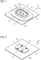
- FIGS. 1 and 2 show a connector 11 for biological data acquisition according to Embodiment 1.
- the connector 11 for biological data acquisition is used as, for example, a garment-side connector for fitting a wearable device and is mounted on cloth 21 of a garment that serves as a mounting object.
- the connector 11 for biological data acquisition includes a housing 12 made of an insulating material.
- two plug contacts PC are retained to protrude perpendicularly to the cloth 21.
- the housing 12 includes a top insulator 13 disposed on a top surface 21A of the cloth 21 and a bottom insulator 14 disposed on a rear surface 21B of the cloth 21.
- the top surface 21A of the cloth 21 is a surface facing the outside of the garment and faces the opposite side from the body surface of a user when the user wears the garment
- the rear surface 21B of the cloth 21 is a surface facing the inside of the garment and faces the body surface of the user when the user wears the garment.
- the top insulator 13 is disposed on the top surface 21A of the cloth 21 via a reinforcement sheet 15 and has a recessed portion 13A opening in the opposite direction from the cloth 21.
- the bottom surface of the recessed portion 13A forms a first exposed surface S1 of flat shape that is exposed on the top surface 21A side of the cloth 21, and the two plug contacts PC protrude perpendicularly to the first exposed surface S1.
- the bottom insulator 14 is disposed directly on the rear surface 21B of the cloth 21 and has a second exposed surface S2 of flat shape that is exposed on the rear surface 21B side of the cloth 21.
- Two electrode surfaces ES are disposed and exposed at the second exposed surface S2.
- the two electrode surfaces ES are arranged to correspond to the two plug contacts PC.
- the first exposed surface S1 and the second exposed surface S2 are defined as extending along an XY plane, the arrangement direction of the two plug contacts PC is referred to as a Y direction, and the direction in which the two plug contacts PC protrude is referred to as a +Z direction.
- the first exposed surface S1 of the top insulator 13 is exposed in the +Z direction, and the second exposed surface S2 of the bottom insulator 14 is exposed in the -Z direction.
- the Z direction coincides with a fitting direction in which the connector 11 for biological data acquisition is fitted to a counter connector (not shown).
- the two electrode surfaces ES are exposed in the state of protruding in the -Z direction from the second exposed surface S2 of the bottom insulator 14.
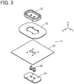
- FIGS. 3 and 4 show assembly views of the connector 11 for biological data acquisition.
- the reinforcement sheet 15 is disposed on the -Z direction side of the top insulator 13, and the cloth 21 is disposed on the -Z direction side of the reinforcement sheet 15.
- Two conductive members 16 are disposed on the -Z direction side of the cloth 21, and the bottom insulator 14 is disposed on the -Z direction side of the two conductive members 16.
- Each conductive member 16 forms both the plug contact PC protruding in the +Z direction from the first exposed surface S1 and the electrode surface ES exposed in the -Z direction from the second exposed surface S2.
- two contact through-holes 13B penetrating the top insulator 13 in the Z direction are formed within the recessed portion 13A of the top insulator 13.
- the recessed portion 13A constitutes a counter connector accommodating portion in which part of a counter connector (not shown) is to be accommodated, and the two contact through-holes 13B correspond to the two plug contacts PC.
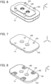
- a step portion 13C recessed is formed along a peripheral portion of the surface, facing in the -Z direction, of the top insulator 13 to surround the two contact through-holes 13B.
- the step portion 13C has a depth substantially the same as the thickness dimension of the reinforcement sheet 15.
- the step portion 13C is provided with four bosses 13D protruding in the -Z direction.
- the bottom insulator 14 includes a flat plate portion 14A, and the flat plate portion 14A is provided with two electrode through-holes 14B penetrating the flat plate portion 14A in the Z direction.
- the two electrode through-holes 14B are arranged to correspond to the two contact through-holes 13B of the top insulator 13.
- the flat plate portion 14A is provided with four boss through-holes 14C corresponding to the four bosses 13D of the top insulator 13 and penetrating the flat plate portion 14A in the Z direction.
- recessed portions 14D are formed at the surface, which forms the second exposed surface S2 and faces in the -Z direction, of the bottom insulator 14 to surround the corresponding boss through-holes 14C.
- the recessed portions 14D are used to accommodate the tips of the bosses 13D of the top insulator 13 that have been passed through the boss through-holes 14C and thermally deformed when the connector 11 for biological data acquisition is assembled.
- the conductive member 16 is a solid member made of an electrically conductive material such as metal and includes: a contact portion 16A of substantially round columnar shape that extends in the Z direction along a fitting axis C; an electrode portion 16B of substantially round columnar shape that is adjacent to the -Z direction side of the contact portion 16A and extends in the Z direction along the fitting axis C; and a flange portion 16C of flange shape that overhangs along an XY plane from a border portion between the contact portion 16A and the electrode portion 16B.
- the conductive member 16 as above can be manufactured by, for instance, press working or cold rolling.
- the fitting axis C is an axis passing the center of the conductive member 16 and extending in the fitting direction in which the connector 11 for biological data acquisition is fitted with a counter connector.
- Each contact through-hole 13B of the top insulator 13 shown in FIG. 5 has an inside diameter slightly larger than a maximum diameter D1 of the contact portion 16A of the conductive member 16 and smaller than a diameter D3 of the flange portion 16C.
- a length L1, in the Z direction, of the contact portion 16A of the conductive member 16 is set to be larger than the thickness, in the Z direction, of a bottom portion of the recessed portion 13A of the top insulator 13.
- Each electrode through-hole 14B of the bottom insulator 14 shown in FIG. 7 has an inside diameter slightly larger than a diameter D2 of the electrode portion 16B of the conductive member 16 and smaller than the diameter D3 of the flange portion 16C.
- the electrode portion 16B of the conductive member 16 includes a round columnar shape portion extending in the Z direction by a length L2 along the fitting axis C and a bulge portion bulging in the -Z direction from the round columnar shape portion.
- the surface of the bulge portion forms the electrode surface ES in a convex shape.
- the length L2, in the Z direction, of the round columnar shape portion is set to be substantially equal to the thickness, in the Z direction, of the flat plate portion 14A of the bottom insulator 14.
- the flange portion 16C of the conductive member 16 has a thickness in the Z direction that is substantially equal to the thickness of the cloth 21.
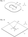
- the reinforcement sheet 15 is used to reinforce the cloth 21 of the garment on which the connector 11 for biological data acquisition is to be mounted, is made of an insulating material, and has an opening portion 15A formed in its center. Further, four cutouts 15B corresponding to the four bosses 13D of the top insulator 13 are formed along the periphery of the opening portion 15A of the reinforcement sheet 15.
- the cloth 21 of the garment is provided with two through-holes 21C corresponding to the two conductive members 16 and four through-holes 21D arranged around the two through-holes 21C and corresponding to the four bosses 13D of the top insulator 13.
- Each through-hole 21C of the cloth 21 has a diameter substantially equal to or slightly larger than the diameter D3 of the flange portion 16C of the conductive member 16.
- the two contact through-holes 13B of the top insulator 13, the two through-holes 21C of the cloth 21, the two conductive members 16, the two electrode through-holes 14B of the bottom insulator 14 are arranged to align correspondingly in the Z direction.
- the four bosses 13D of the top insulator 13, the four cutouts 15B of the reinforcement sheet 15, the four through-holes 21D of the cloth 21, and the four boss through-holes 14C of the bottom insulator 14 are arranged to align correspondingly in the Z direction.
- the reinforcement sheet 15 and the cloth 21 are sequentially disposed over the surface, facing in the -Z direction, of the top insulator 13 such that the four bosses 13D of the top insulator 13 pass through the four cutouts 15B of the reinforcement sheet 15 and the four through-holes 21D of the cloth 21.
- a peripheral portion of the opening portion 15A of the reinforcement sheet 15 is accommodated in the step portion 13C of the top insulator 13, and the two through-holes 21C of the cloth 21 are situated on the - Z direction side of the two contact through-holes 13B of the top insulator 13 through the opening portion 15A of the reinforcement sheet 15.
- the contact portions 16A of the two conductive members 16 are inserted into the two through-holes 21C of the cloth 21 and the two contact through-holes 13B of the top insulator 13 from the -Z direction.
- the contact through-holes 13B of the top insulator 13 have an inside diameter slightly larger than the diameter D1 of the contact portions 16A of the conductive members 16 and smaller than the diameter D3 of the flange portions 16C, and the through-holes 21C of the cloth 21 have a diameter substantially equal to or slightly larger than the diameter D3 of the flange portions 16C of the conductive members 16.
- the flange portions 16C of the conductive members 16 abut the surface, facing in the -Z direction, of the top insulator 13 around the contact through-holes 13B.
- the bottom insulator 14 is disposed on the surface, facing in the -Z direction, of the cloth 21 from the -Z direction and pressed in the +Z direction against the top insulator 13.
- the electrode through-holes 14B of the bottom insulator 14 have an inside diameter slightly larger than the diameter D2 of the electrode portions 16B of the conductive members 16 and smaller than the diameter D3 of the flange portions 16C; accordingly, when the bottom insulator 14 is disposed on the -Z direction side of the cloth 21 while the electrode portions 16B of the conductive members 16 are inserted into the electrode through-holes 14B of the bottom insulator 14, the surface, facing in the +Z direction, of the bottom insulator 14 around the electrode through-holes 14B abuts the flange portions 16C of the conductive members 16 as shown in FIG. 13 .
- the flange portions 16C of the conductive members 16 have a thickness in the Z direction that is substantially equal to the thickness of the cloth 21, the flange portions 16C of the conductive members 16 and the cloth 21 are sandwiched between the surface, facing in the -Z direction, of the top insulator 13 and the surface, facing in the +Z direction, of the bottom insulator 14.
- the four bosses 13D of the top insulator 13 sequentially passing through the four cutouts 15B of the reinforcement sheet 15 and the four through-holes 21D of the cloth 21 pass through the four boss through-holes 14C of the bottom insulator 14 and protrude on the -Z direction side of the bottom insulator 14. Then, the tip portions of the four bosses 13D protruding from the bottom insulator 14 on the -Z direction side are thermally deformed in the recessed portions 14D of the bottom insulator 14, whereby the top insulator 13 and the bottom insulator 14 are fixed together. Thus, the assembling operation of the connector 11 for biological data acquisition is completed.
- the electrode portion 16B of each conductive member 16 is inserted in the corresponding electrode through-hole 14B of the bottom insulator 14, and the length of the round columnar shape portion of the electrode portion 16B in the Z direction is substantially equal to the thickness of the flat plate portion 14A of the bottom insulator 14 in the Z direction, as shown in FIG. 14 . Consequently, the convex electrode surface ES formed of the surface of the bulge portion adjacent to the -Z direction side of the round columnar shape portion of the conductive member 16 protrudes in the -Z direction from the second exposed surface S2 formed of the surface, facing in the -Z direction, of the bottom insulator 14.
- each conductive member 16 passes through the corresponding contact through-hole 13B of the top insulator 13 and protrudes in the +Z direction from the first exposed surface S 1 formed of the bottom surface of the recessed portion 13A; thus, the contact portion 16A constitutes the plug contact PC.
- a counter connector (not shown) to the connector 11 for biological data acquisition such that a part of the counter connector is accommodated in the recessed portion 13A of the top insulator 13 and that counter contacts of the counter connector are connected to the plug contacts PC, biological data of the user acquired through the electrode surfaces ES can be transmitted from the contact portions 16A of the conductive members 16 to a device (not shown) such as a measurement device or a communication device via the counter connector with high accuracy, without use of wiring or the like.
- the electrode surface ES used to acquire biological data of the user and the plug contact PC used to transmit the acquired biological data to the counter connector are together formed of a single conductive member 16; therefore, acquisition and transmission of biological data can be carried out only by mounting the connector 11 for biological data acquisition onto the garment, thus making it possible to reduce the size of the device that is mounted on the garment to acquire biological data.
- both the contact portion 16A and the electrode portion 16B of the conductive member 16 have substantially round columnar shapes, it suffices if the portions 16A and 16B have columnar shapes extending in the Z direction along the fitting axis C.
- the cross-sectional shapes of the portions 16A and 16B when cut in a plane parallel to an XY plane are each not limited to a circular shape and may be an elliptical shape, a rectangular shape, another polygonal shape, or the like.
- FIGS. 15 and 16 show a connector 31 for biological data acquisition according to Embodiment 2.
- the connector 31 for biological data acquisition is mounted on the cloth 21 of the garment and used as, for example, a garment-side connector for fitting a wearable device, as with the connector 11 for biological data acquisition according to Embodiment 1.
- the connector 31 for biological data acquisition includes the housing 12 made of an insulating material, and the two plug contacts PC are retained in the housing 12, as with the connector 11 for biological data acquisition according to Embodiment 1.
- the housing 12 includes the top insulator 13 disposed on the top surface 21A of the cloth 21 and the bottom insulator 14 disposed on the rear surface 21B of the cloth 21.
- the two plug contacts PC protrude perpendicularly to the first exposed surface S1 formed of the bottom surface of the recessed portion 13A of the top insulator 13.
- the two electrode surfaces ES are disposed and exposed at the second exposed surface S2 formed in the bottom insulator 14.
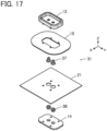
- FIGS. 17 and 18 show assembly views of the connector 31 for biological data acquisition.
- the reinforcement sheet 15 is disposed on the -Z direction side of the top insulator 13
- two contact members 37 are disposed on the -Z direction side of the reinforcement sheet 15, and the cloth 21 is disposed on the -Z direction side of the two contact members 37.
- two electrode members 38 are disposed on the -Z direction side of the cloth 21, and the bottom insulator 14 is disposed on the -Z direction side of the two electrode members 38.
- the connector 31 for biological data acquisition according to Embodiment 2 is configured such that, in the connector 11 for biological data acquisition according to Embodiment 1, the two conductive members 16 are replaced by the two contact members 37 and the two electrode members 38, while the top insulator 13, the bottom insulator 14, and the reinforcement sheet 15 are identical to those used in Embodiment 1.
- the contact member 37 is made of an electrically conductive material such as metal and includes: a tubular portion 37A of cylindrical shape extending in the Z direction along the fitting axis C; and a contact-side flange 37B overhanging from a -Z directional end portion of the tubular portion 37A along an XY plane.
- the tubular portion 37A is provided in its interior with a recessed portion 37C opening in the -Z direction.
- Each contact through-hole 13B of the top insulator 13 shown in FIG. 5 has an inside diameter slightly larger than a maximum diameter D11 of the tubular portion 37A of the contact member 37 and smaller than a diameter D13 of the contact-side flange 37B.
- a length L11, in the Z direction, of the tubular portion 37A is set to be larger than the thickness, in the Z direction, of the bottom portion of the recessed portion 13A of the top insulator 13.
- the electrode member 38 is a solid member made of an electrically conductive material such as metal and includes: a first round columnar portion 38A of substantially round columnar shape that extends in the Z direction along the fitting axis C; a second round columnar portion 38B of substantially round columnar shape that is adjacent to the -Z direction side of the first round columnar portion 38A and extends in the Z direction along the fitting axis C; and an electrode-side flange 38C of flange shape that overhangs along an XY plane from the border portion between the first round columnar portion 38A and the second round columnar portion 38B.
- the first round columnar portion 38A is provided on its outer peripheral portion with four ribs 38D linearly extending in the Z direction and arranged at intervals of 90-degree rotational angles about the fitting axis C.
- the electrode member 38 as above can be manufactured by, for instance, press working or cold rolling.
- Each electrode through-hole 14B of the bottom insulator 14 shown in FIG. 7 has an inside diameter slightly larger than a diameter D22 of the second round columnar portion 38B of the electrode member 38 and smaller than a diameter D23 of the electrode-side flange 38C.
- the second round columnar portion 38B of the electrode member 38 includes a round columnar shape portion extending in the Z direction by a length L22 along the fitting axis C and a bulge portion bulging in the -Z direction from the round columnar shape portion.
- the surface of the bulge portion forms an electrode surface ES in a convex shape.
- the length L22, in the Z direction, of the round columnar shape portion is set to be substantially equal to the thickness, in the Z direction, of the flat plate portion 14A of the bottom insulator 14.
- a maximum diameter D21 of the first round columnar portion 38A where the ribs 38D are present is slightly larger than an inside diameter D12 of the recessed portion 37C of the tubular portion 37A of the contact member 37, and a length L21, in the Z direction, of the first round columnar portion 38A is formed to be smaller than a depth, in the Z direction, of the recessed portion 37C of the tubular portion 37A of the contact member 37.
- the electrode member 38 may be provided with a spring portion which is not shown such that the contact member 37 and the electrode member 38 elastically contact each other by use of the spring portion.
- the contact member 37 and the electrode member 38 form a contact portion and an electrode portion in the conductive member 36, respectively, and the contact-side flange 37B of the contact member 37 and the electrode-side flange 38C of the electrode member 38 are stacked in the Z direction to form a flange portion 36C in the conductive member 36.
- the diameter D13 of the contact-side flange 37B of the contact member 37 and the diameter D23 of the electrode-side flange 38C of the electrode member 38 shown in FIGS. 20 and 22 are equal to each other, and the sum of the thickness of the contact-side flange 37B in the Z direction and the thickness of the electrode-side flange 38C in the Z direction, that is, the thickness of the flange portion 36C in the Z direction is formed to be substantially equal to the thickness of the cloth 21.
- the reinforcement sheet 15 is disposed on the surface, facing in the -Z direction, of the top insulator 13 such that the four bosses 13D of the top insulator 13 separately pass through the four cutouts 15B of the reinforcement sheet 15, and the tubular portions 37A of the two contact members 37 are inserted into the two contact through-holes 13B of the top insulator 13 through the opening portion 15A of the reinforcement sheet 15 from the -Z direction.
- the cloth 21 is disposed on the surface, facing in the -Z direction, of the reinforcement sheet 15 such that the four bosses 13D of the top insulator 13 separately pass through the four through-holes 21D of the cloth 21, and the first round columnar portions 38A of the two electrode members 38 are press-fitted into the recessed portions 37C of the two contact members 37 through the two through-holes 21C of the cloth 21 from the -Z direction.
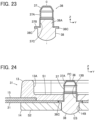
- the two conductive members 36 each of which is as shown in FIG. 23 are formed.
- the bottom insulator 14 is disposed on the surface, facing in the -Z direction, of the cloth 21 from the -Z direction and pressed in the +Z direction against the top insulator 13.
- the flange portion 36C of the conductive member 36 is sandwiched between the surface, facing in the -Z direction, of the top insulator 13 and the surface, facing in the +Z direction, of the bottom insulator 14, so that the conductive member 36 is fixed to the top insulator 13 and the bottom insulator 14, as shown in FIG. 24 .
- the convex electrode surface ES of the electrode member 38 that is a constituent of each conductive member 36 protrudes in the -Z direction from the second exposed surface S2 formed of the surface, facing in the -Z direction, of the bottom insulator 14.
- the tubular portion 37A of the contact member 37 that is a constituent of each conductive member 36 passes through the contact through-hole 13B of the top insulator 13 and protrudes in the +Z direction from the first exposed surface S1 formed of the bottom surface of the recessed portion 13A; thus, the tubular portion 37A constitutes the plug contacts PC.
- the connector 31 for biological data acquisition by contact of the electrode surfaces ES protruding from the second exposed surface S2 with the body surface of a user, biological data of the user can be acquired via the electrode surface ES as with the connector 11 for biological data acquisition according to Embodiment 1. Furthermore, when a counter connector (not shown) is fitted to the connector 31 for biological data acquisition such that counter contacts of the counter connector are connected to the plug contacts PC, biological data of the user acquired through the electrode surfaces ES can be transmitted from the contact members 37 of the conductive members 36 to a device (not shown) such as a measurement device or a communication device via the counter connector with high accuracy, without use of wiring or the like.
- both the electrode surface ES used to acquire biological data of the user and the plug contact PC used to transmit the acquired biological data to the counter connector are formed of a single conductive member 36; therefore, acquisition and transmission of biological data can be carried out only by mounting the connector 31 for biological data acquisition onto the garment, thus making it possible to reduce the size of the device that is mounted on the garment to acquire biological data.
- the tubular portion 37A of the contact member 37 has a cylindrical shape
- the first round columnar portion 38A and the second round columnar portion 38B of the electrode member 38 have substantially round columnar shapes; however, it suffices if the portions 37A, 38A, and 38B each have a columnar shape extending in the Z direction along the fitting axis C.
- the cross-sectional shapes of the portions 37A, 38A, and 38B when cut in a plane parallel to an XY plane are each not limited to a circular shape and may be an elliptical shape, a rectangular shape, another polygonal shape, or the like.
- the cross-sectional shape of the first round columnar portion 38A and that of the recessed portion 37C correspond to each other.
- the contact member 37 and the electrode member 38 are configured to be separate components, it is not necessary to form the contact member 37 and the electrode member 38 from the same material.
- the contact member 37 may be formed from a material suitable for contact with a counter contact of a counter connector, while the electrode member 38 may be formed from a material suitable for contact with the body surface of a user.
- Various types of biological data of a user can be acquired by contact of the electrode surfaces ES of the conductive members 16, 36 in Embodiments 1 and 2 with the body surface of the user, and the connector 11, 31 for biological data acquisition according to Embodiments 1 and 2 has the two conductive members 16, 36. Therefore, the use of only the connector 11, 31 for biological data acquisition allows acquisition of even a heart rate, an electrocardiographic waveform, and other types of biological data with high accuracy.
- the number of conductive members is not limited to two, and a connector for biological data acquisition may be configured to have three or more conductive members.
- the electrode portion 16B of the conductive member 16 and the electrode member 38 of the conductive member 36 each of which has the electrode surface ES protruding from the second exposed surface S2 are made of metal or the like, the invention is not limited thereto, and the electrode portion 16B and the electrode member 38 may be formed from a conductive material having flexibility such as conductive rubber.
- FIG. 25 shows a connector 41 for biological data acquisition according to Embodiment 3.
- the connector 41 for biological data acquisition is configured such that, in the connector 11 for biological data acquisition according to Embodiment 1, the bottom insulator 14 is replaced by a bottom insulator 44, and otherwise has the same configuration as the connector 11 for biological data acquisition according to Embodiment 1.
- the electrode surfaces ES of the two conductive members 16 are exposed in the state of protruding in the -Z direction from the second exposed surface S2 of the bottom insulator 44, as with the connector 11 for biological data acquisition according to Embodiment 1.
- the bottom insulator 44 has lubricant retaining portions 44A constituted of annular grooves separately formed along the outer peripheries of the two electrode surfaces ES exposed at the second exposed surface S2.
- the bottom insulator 44 has the same configuration as that of the bottom insulator 14 in Embodiment 1 except for the provision of those lubricant retaining portions 44A.
- the electrode surfaces ES To acquire biological data of a user via the electrode surfaces ES, it is desirable that the electrode surfaces ES closely adhere to the body surface of the user, and for instance, a medical lubricant may be applied on the body surface of the user to contact the electrode surfaces ES with the body surface.
- the lubricant retaining portions 44A constituted of grooves are formed along the outer peripheries of the two electrode surfaces ES exposed at the second exposed surface S2 of the bottom insulator 44 in the connector 41 for biological data acquisition according to Embodiment 3, when the electrode surfaces ES are brought into contact with the body surface of the user, the medical lubricant applied on the body surface of the user is retained inside the lubricant retaining portions 44A.
- the lubricant retaining portions 44A in Embodiment 3 may be adopted for the connector 31 for biological data acquisition according to Embodiment 2 to be formed in the bottom insulator 14 of the connector 31 for biological data acquisition.
- FIG. 26 shows a connector 51 for biological data acquisition according to Embodiment 4.
- the connector 51 for biological data acquisition is configured such that, in the connector 11 for biological data acquisition according to Embodiment 1, a pressure-sensitive adhesive layer 52 is disposed on the second exposed surface S2, facing in the -Z direction, of the bottom insulator 14, and otherwise has the same configuration as the connector 11 for biological data acquisition according to Embodiment 1.
- the pressure-sensitive adhesive layer 52 is used to adhere the connector 51 for biological data acquisition to the body surface of a user by utilizing its adhesion and can be formed using a conventional elastomer such as silicone rubber or urethane rubber.
- the adhesion between the electrode surfaces ES and the body surface of the user enhances, thus enabling to acquire biological data via the electrode surfaces ES with high accuracy.
- the pressure-sensitive adhesive layer 52 in Embodiment 4 may be adopted for the connector 31 for biological data acquisition according to Embodiment 2 or the connector 41 for biological data acquisition according to Embodiment 3.
- the bottom insulator 14 in the connector 11 for biological data acquisition according to Embodiment 1 and the connector 31 for biological data acquisition according to Embodiment 2 and the bottom insulator 44 in the connector 41 for biological data acquisition according to Embodiment 3 may be formed from an insulating material having pressure-sensitive adhesive properties.
- an insulating material having pressure-sensitive adhesive properties use may be made of, for example, an elastomer including silicone rubber or urethane rubber.
- the connector 11, 31, 41 for biological data acquisition adheres to the body surface of the user, and this enhances the adhesion between the electrode surfaces ES and the body surface of the user, thus enabling to acquire biological data via the electrode surfaces ES with high accuracy.
- the top and bottom insulators 13 and 14 in the connector 11 for biological data acquisition according to Embodiment 1, the connector 31 for biological data acquisition according to Embodiment 2, and the connector 51 for biological data acquisition according to Embodiment 4 and the top and bottom insulators 13 and 44 in the connector 41 for biological data acquisition according to Embodiment 3 may be formed from an insulating material having flexibility such as an elastomer.
- the connector 11, 31, 41, 51 for biological data acquisition can be bent to follow the body surface of a user, and this further enhances the adhesion between the electrode surfaces ES and the body surface of the user.
- the electrode surfaces ES of the respective conductive members 16, 36 may be provided with asperities including, for example, grooves and the like to roughen the electrode surfaces ES.
- asperities including, for example, grooves and the like to roughen the electrode surfaces ES.
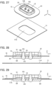
- FIG. 27 shows a connector 61 for biological data acquisition according to Embodiment 5 and cloth 71 of a garment that serves as a mounting object.
- the connector 61 for biological data acquisition includes: the top insulator 13 disposed on the +Z directional surface of the reinforcement sheet 15; and the two plug contacts PC protruding in the +Z direction from the first exposed surface S1 formed of the bottom surface of the recessed portion 13A of the top insulator 13.
- the connector 61 for biological data acquisition is not retained by the cloth 71 of the garment, and the cloth 71 is disposed away in the -Z direction from the connector 61 for biological data acquisition.
- the cloth 71 is provided with an opening portion 71A corresponding to the connector 61 for biological data acquisition.
- the connector 61 for biological data acquisition includes a bottom insulator 64 disposed on the -Z direction side of the reinforcement sheet 15.
- the +Z directional surface of the bottom insulator 64 makes contact with the -Z directional surface of the reinforcement sheet 15 and the -Z directional surface of the top insulator 13, and the flange portions 16C of the two conductive members 16 are sandwiched between the top insulator 13 and the bottom insulator 64; in this state, the top insulator 13 and the bottom insulator 64 are fixed to each other.
- the two conductive members 16 form the two plug contacts PC and the two electrode surfaces ES, the two plug contacts PC protrude in the +Z direction from the first exposed surface S1 of the top insulator 13, and the two electrode surfaces ES protrude in the -Z direction from the second exposed surface S2 of the bottom insulator 64.
- the connector 61 for biological data acquisition as above is disposed on the cloth 71 of the garment as shown in FIG. 29 .
- the opening portion 71A of the cloth 71 is slightly larger in size than the bottom insulator 64.
- the bottom insulator 64 is inserted in the opening portion 71A, and the reinforcement sheet 15 makes contact with the surface of the cloth 71 around the opening portion 71A.
- the reinforcement sheet 15 is sewn to the cloth 71, whereby the connector 61 for biological data acquisition can be mounted on the cloth 71.
- the connector 61 for biological data acquisition With the use of the connector 61 for biological data acquisition according to Embodiment 5, it is not necessary to sandwich the cloth 71 between the top insulator 13 and the bottom insulator 64 in the assembling operation of the connector 61 for biological data acquisition, and the connector 61 for biological data acquisition can be mounted on the cloth 71 after the connector 61 for biological data acquisition is assembled.
- the garment can be used as so-called smart clothes that can acquire biological data of a user only be being worn by the user.
- the connector 61 for biological data acquisition can be removed and attached to another garment for reuse.
- various methods may be used such as bonding and fixing by means of a zip fastener, in addition to sewing.
- the top insulator 13 and the bottom insulator 64 in the connector 61 for biological data acquisition may be formed separately from an insulating material having flexibility, such as an elastomer, to make the connector 61 for biological data acquisition bendable to follow the body surface of a user.
- the two conductive members 16 may be formed by insert-molding, while the top insulator 13, the bottom insulator 64, and the reinforcement sheet 15 are integrally formed from an insulating material.
- the connector 61 for biological data acquisition that is bendable may be formed by molding using an insulating material having flexibility such as an elastomer.
- the connector 31 for biological data acquisition according to Embodiment 2 may also be configured to be mounted on cloth after the connector is assembled, in the same manner.
Landscapes
- Health & Medical Sciences (AREA)
- Life Sciences & Earth Sciences (AREA)
- Biomedical Technology (AREA)
- Molecular Biology (AREA)
- Veterinary Medicine (AREA)
- Biophysics (AREA)
- Pathology (AREA)
- Engineering & Computer Science (AREA)
- Public Health (AREA)
- Heart & Thoracic Surgery (AREA)
- Medical Informatics (AREA)
- Physics & Mathematics (AREA)
- Surgery (AREA)
- Animal Behavior & Ethology (AREA)
- General Health & Medical Sciences (AREA)
- Cardiology (AREA)
- Physiology (AREA)
- Measurement And Recording Of Electrical Phenomena And Electrical Characteristics Of The Living Body (AREA)
- Coupling Device And Connection With Printed Circuit (AREA)
Abstract
Description
- The present invention relates to a connector for biological data acquisition, particularly to a connector for biological data acquisition that is mounted on a mounting object constituted of a wearing article worn by a user and is fitted to a counter connector.
- An electrode unit for acquiring a heart rate and other biological data of a user is disclosed in, for example,
JP 2020-18783 A badge portion 1 of pin badge type and afastener portion 3 used to fasten thebadge portion 1 to agarment 2, as shown inFIG. 30 . Thebadge portion 1 includes anelectrode portion 4 and apin 5 formed to protrude on theelectrode portion 4. Thebadge portion 1 is fastened to thegarment 2 by sticking thepin 5 into thegarment 2 and inserting the tip of thepin 5 protruding from thegarment 2 into aninsertion hole 6 of thefastener portion 3. - The user's biological data is acquired when the
electrode portion 4 is brought into contact with or brought closer to abody surface 7 of the user, and the acquired biological data is transmitted to an external device (not shown) such as a measurement device or a communication device through acable 8 connected to thefastener portion 3. - However, since biological data is transmitted to the external device through the
cable 8, a resistance value in the transmission path increases due to the use of thecable 8, and this may result in lower accuracy of the transmitted biological data. - While it is possible to connect a connector which is not shown to the
cable 8 to transmit biological data to a measurement device, a communication device, or the like via the connector, even in this case, an increase in a resistance value due to the use of thecable 8 is not avoidable, and this also causes another problem in that connecting the connector to the electrode unit shown inFIG. 30 results in an increased size of a device to be mounted on thegarment 2 to acquire biological data. - The present invention has been made to solve the conventional problems described above and aims at providing a small-sized connector for biological data acquisition that is capable of acquiring and transmitting biological data of a user with high accuracy.
- A connector for biological data acquisition according to the present invention is one mounted on a mounting object constituted of a wearing article worn by a user and is fitted to a counter connector along a fitting direction, the connector for biological data acquisition comprising:
- a housing configured to be attached to the mounting object and including a first exposed surface that faces an opposite side from a body surface of the user and a second exposed surface that faces the body surface; and
- a plurality of conductive members each extending along the fitting direction and retained by the housing in a state of passing through the housing in the fitting direction from the first exposed surface to the second exposed surface,
- wherein each of the plurality of conductive members includes a contact portion having electrical conductivity and an electrode portion having electrical conductivity, the contact portion protruding from the first exposed surface of the housing and being connected to a counter contact of the counter connector when the connector for biological data acquisition is fitted to the counter connector, the electrode portion protruding from the second exposed surface of the housing and being used to acquire biological data of the user.
-
-
FIG. 1 is a perspective view of a connector for biological data acquisition according toEmbodiment 1 when viewed from an obliquely upper position. -
FIG. 2 is a perspective view of the connector for biological data acquisition according toEmbodiment 1 when viewed from an obliquely lower position. -
FIG. 3 is an assembly view of the connector for biological data acquisition according toEmbodiment 1 when viewed from an obliquely upper position. -
FIG. 4 is an assembly view of the connector for biological data acquisition according toEmbodiment 1 when viewed from an obliquely lower position. -
FIG. 5 is a perspective view of a top insulator used inEmbodiment 1 when viewed from an obliquely upper position. -
FIG. 6 is a perspective view of the top insulator used inEmbodiment 1 when viewed from an obliquely lower position. -
FIG. 7 is a perspective view of a bottom insulator used inEmbodiment 1 when viewed from an obliquely upper position. -
FIG. 8 is a perspective view of the bottom insulator used inEmbodiment 1 when viewed from an obliquely lower position. -
FIG. 9 is a perspective view showing a conductive member used inEmbodiment 1. -
FIG. 10 is a cross-sectional view showing the conductive member used inEmbodiment 1. -
FIG. 11 is a perspective view showing a reinforcement sheet used inEmbodiment 1. -
FIG. 12 is a perspective view showing a mounting object used inEmbodiment 1. -
FIG. 13 is a perspective cross-sectional view showing the connector for biological data acquisition according toEmbodiment 1. -
FIG. 14 is a partial, cross-sectional front view showing the connector for biological data acquisition according toEmbodiment 1. -
FIG. 15 is a perspective view of a connector for biological data acquisition according toEmbodiment 2 when viewed from an obliquely upper position. -
FIG. 16 is a perspective view of the connector for biological data acquisition according toEmbodiment 2 when viewed from an obliquely lower position. -
FIG. 17 is an assembly view of the connector for biological data acquisition according toEmbodiment 2 when viewed from an obliquely upper position. -
FIG. 18 is an assembly view of the connector for biological data acquisition according toEmbodiment 2 when viewed from an obliquely lower position. -
FIG. 19 is a perspective view showing a contact member used inEmbodiment 2. -
FIG. 20 is a cross-sectional view showing the contact member used inEmbodiment 2. -
FIG. 21 is a perspective view showing an electrode member used inEmbodiment 2. -
FIG. 22 is a cross-sectional view showing the electrode member used inEmbodiment 2. -
FIG. 23 is a cross-sectional view showing a conductive member used inEmbodiment 2. -
FIG. 24 is a partial, cross-sectional front view showing the connector for biological data acquisition according toEmbodiment 2. -
FIG. 25 is a perspective cross-sectional view showing a connector for biological data acquisition according toEmbodiment 3. -
FIG. 26 is a partial, cross-sectional front view showing a connector for biological data acquisition according toEmbodiment 4. -
FIG. 27 is a perspective view showing a connector for biological data acquisition according to Embodiment 5 being aligned with a mounting object. -
FIG. 28 is a cross-sectional view showing the connector for biological data acquisition according toEmbodiment 5 being aligned with the mounting object. -
FIG. 29 is a cross-sectional front view showing the connector for biological data acquisition according toEmbodiment 5 that is mounted on the mounting object. -
FIG. 30 is a cross-sectional view showing a conventional electrode unit. - Embodiments of the present invention are described below based on the accompanying drawings.
-
FIGS. 1 and 2 show aconnector 11 for biological data acquisition according to Embodiment 1. Theconnector 11 for biological data acquisition is used as, for example, a garment-side connector for fitting a wearable device and is mounted oncloth 21 of a garment that serves as a mounting object. - The
connector 11 for biological data acquisition includes ahousing 12 made of an insulating material. In thehousing 12, two plug contacts PC are retained to protrude perpendicularly to thecloth 21. - The
housing 12 includes atop insulator 13 disposed on atop surface 21A of thecloth 21 and abottom insulator 14 disposed on arear surface 21B of thecloth 21. Thetop surface 21A of thecloth 21 is a surface facing the outside of the garment and faces the opposite side from the body surface of a user when the user wears the garment, and therear surface 21B of thecloth 21 is a surface facing the inside of the garment and faces the body surface of the user when the user wears the garment. - As shown in
FIG. 1 , thetop insulator 13 is disposed on thetop surface 21A of thecloth 21 via areinforcement sheet 15 and has a recessedportion 13A opening in the opposite direction from thecloth 21. The bottom surface of therecessed portion 13A forms a first exposed surface S1 of flat shape that is exposed on thetop surface 21A side of thecloth 21, and the two plug contacts PC protrude perpendicularly to the first exposed surface S1. - As shown in
FIG. 2 , thebottom insulator 14 is disposed directly on therear surface 21B of thecloth 21 and has a second exposed surface S2 of flat shape that is exposed on therear surface 21B side of thecloth 21. Two electrode surfaces ES are disposed and exposed at the second exposed surface S2. The two electrode surfaces ES are arranged to correspond to the two plug contacts PC. - For convenience, the first exposed surface S1 and the second exposed surface S2 are defined as extending along an XY plane, the arrangement direction of the two plug contacts PC is referred to as a Y direction, and the direction in which the two plug contacts PC protrude is referred to as a +Z direction. The first exposed surface S1 of the
top insulator 13 is exposed in the +Z direction, and the second exposed surface S2 of thebottom insulator 14 is exposed in the -Z direction. The Z direction coincides with a fitting direction in which theconnector 11 for biological data acquisition is fitted to a counter connector (not shown). - The two electrode surfaces ES are exposed in the state of protruding in the -Z direction from the second exposed surface S2 of the
bottom insulator 14. -
FIGS. 3 and4 show assembly views of theconnector 11 for biological data acquisition. Thereinforcement sheet 15 is disposed on the -Z direction side of thetop insulator 13, and thecloth 21 is disposed on the -Z direction side of thereinforcement sheet 15. Twoconductive members 16 are disposed on the -Z direction side of thecloth 21, and thebottom insulator 14 is disposed on the -Z direction side of the twoconductive members 16. - Each
conductive member 16 forms both the plug contact PC protruding in the +Z direction from the first exposed surface S1 and the electrode surface ES exposed in the -Z direction from the second exposed surface S2. - As shown in
FIG. 5 , two contact through-holes 13B penetrating thetop insulator 13 in the Z direction are formed within the recessedportion 13A of thetop insulator 13. The recessedportion 13A constitutes a counter connector accommodating portion in which part of a counter connector (not shown) is to be accommodated, and the two contact through-holes 13B correspond to the two plug contacts PC. - As shown in
FIG. 6 , astep portion 13C recessed is formed along a peripheral portion of the surface, facing in the -Z direction, of thetop insulator 13 to surround the two contact through-holes 13B. Thestep portion 13C has a depth substantially the same as the thickness dimension of thereinforcement sheet 15. Thestep portion 13C is provided with fourbosses 13D protruding in the -Z direction. - As shown in
FIG. 7 , thebottom insulator 14 includes aflat plate portion 14A, and theflat plate portion 14A is provided with two electrode through-holes 14B penetrating theflat plate portion 14A in the Z direction. The two electrode through-holes 14B are arranged to correspond to the two contact through-holes 13B of thetop insulator 13. - Further, the
flat plate portion 14A is provided with four boss through-holes 14C corresponding to the fourbosses 13D of thetop insulator 13 and penetrating theflat plate portion 14A in the Z direction. - As shown in
FIG. 8 , recessedportions 14D are formed at the surface, which forms the second exposed surface S2 and faces in the -Z direction, of thebottom insulator 14 to surround the corresponding boss through-holes 14C. The recessedportions 14D are used to accommodate the tips of thebosses 13D of thetop insulator 13 that have been passed through the boss through-holes 14C and thermally deformed when theconnector 11 for biological data acquisition is assembled. - As shown in
FIGS. 9 and 10 , theconductive member 16 is a solid member made of an electrically conductive material such as metal and includes: acontact portion 16A of substantially round columnar shape that extends in the Z direction along a fitting axis C; anelectrode portion 16B of substantially round columnar shape that is adjacent to the -Z direction side of thecontact portion 16A and extends in the Z direction along the fitting axis C; and aflange portion 16C of flange shape that overhangs along an XY plane from a border portion between thecontact portion 16A and theelectrode portion 16B. Theconductive member 16 as above can be manufactured by, for instance, press working or cold rolling. - The fitting axis C is an axis passing the center of the
conductive member 16 and extending in the fitting direction in which theconnector 11 for biological data acquisition is fitted with a counter connector. - Each contact through-
hole 13B of thetop insulator 13 shown inFIG. 5 has an inside diameter slightly larger than a maximum diameter D1 of thecontact portion 16A of theconductive member 16 and smaller than a diameter D3 of theflange portion 16C. A length L1, in the Z direction, of thecontact portion 16A of theconductive member 16 is set to be larger than the thickness, in the Z direction, of a bottom portion of the recessedportion 13A of thetop insulator 13. - Each electrode through-
hole 14B of thebottom insulator 14 shown inFIG. 7 has an inside diameter slightly larger than a diameter D2 of theelectrode portion 16B of theconductive member 16 and smaller than the diameter D3 of theflange portion 16C. Theelectrode portion 16B of theconductive member 16 includes a round columnar shape portion extending in the Z direction by a length L2 along the fitting axis C and a bulge portion bulging in the -Z direction from the round columnar shape portion. The surface of the bulge portion forms the electrode surface ES in a convex shape. The length L2, in the Z direction, of the round columnar shape portion is set to be substantially equal to the thickness, in the Z direction, of theflat plate portion 14A of thebottom insulator 14. - The
flange portion 16C of theconductive member 16 has a thickness in the Z direction that is substantially equal to the thickness of thecloth 21. - As shown in
FIG. 11 , thereinforcement sheet 15 is used to reinforce thecloth 21 of the garment on which theconnector 11 for biological data acquisition is to be mounted, is made of an insulating material, and has anopening portion 15A formed in its center. Further, fourcutouts 15B corresponding to the fourbosses 13D of thetop insulator 13 are formed along the periphery of theopening portion 15A of thereinforcement sheet 15. - As shown in
FIG. 12 , thecloth 21 of the garment is provided with two through-holes 21C corresponding to the twoconductive members 16 and four through-holes 21D arranged around the two through-holes 21C and corresponding to the fourbosses 13D of thetop insulator 13. - Each through-
hole 21C of thecloth 21 has a diameter substantially equal to or slightly larger than the diameter D3 of theflange portion 16C of theconductive member 16. - The two contact through-
holes 13B of thetop insulator 13, the two through-holes 21C of thecloth 21, the twoconductive members 16, the two electrode through-holes 14B of thebottom insulator 14 are arranged to align correspondingly in the Z direction. - The four
bosses 13D of thetop insulator 13, the fourcutouts 15B of thereinforcement sheet 15, the four through-holes 21D of thecloth 21, and the four boss through-holes 14C of thebottom insulator 14 are arranged to align correspondingly in the Z direction. - When the
connector 11 for biological data acquisition is assembled, first, thereinforcement sheet 15 and thecloth 21 are sequentially disposed over the surface, facing in the -Z direction, of thetop insulator 13 such that the fourbosses 13D of thetop insulator 13 pass through the fourcutouts 15B of thereinforcement sheet 15 and the four through-holes 21D of thecloth 21. At this time, a peripheral portion of theopening portion 15A of thereinforcement sheet 15 is accommodated in thestep portion 13C of thetop insulator 13, and the two through-holes 21C of thecloth 21 are situated on the - Z direction side of the two contact through-holes 13B of thetop insulator 13 through theopening portion 15A of thereinforcement sheet 15. - Further, the
contact portions 16A of the twoconductive members 16 are inserted into the two through-holes 21C of thecloth 21 and the two contact through-holes 13B of thetop insulator 13 from the -Z direction. The contact through-holes 13B of thetop insulator 13 have an inside diameter slightly larger than the diameter D1 of thecontact portions 16A of theconductive members 16 and smaller than the diameter D3 of theflange portions 16C, and the through-holes 21C of thecloth 21 have a diameter substantially equal to or slightly larger than the diameter D3 of theflange portions 16C of theconductive members 16. - Accordingly, when the
contact portions 16A of theconductive members 16 are inserted into the through-holes 21C of thecloth 21 and the contact through-holes 13B of thetop insulator 13, theflange portions 16C of theconductive members 16 abut the surface, facing in the -Z direction, of thetop insulator 13 around the contact through-holes 13B. - In this state, while the
electrode portions 16B of the twoconductive members 16 are inserted into the two electrode through-holes 14B of thebottom insulator 14, thebottom insulator 14 is disposed on the surface, facing in the -Z direction, of thecloth 21 from the -Z direction and pressed in the +Z direction against thetop insulator 13. - The electrode through-
holes 14B of thebottom insulator 14 have an inside diameter slightly larger than the diameter D2 of theelectrode portions 16B of theconductive members 16 and smaller than the diameter D3 of theflange portions 16C; accordingly, when thebottom insulator 14 is disposed on the -Z direction side of thecloth 21 while theelectrode portions 16B of theconductive members 16 are inserted into the electrode through-holes 14B of thebottom insulator 14, the surface, facing in the +Z direction, of thebottom insulator 14 around the electrode through-holes 14B abuts theflange portions 16C of theconductive members 16 as shown inFIG. 13 . - Since the
flange portions 16C of theconductive members 16 have a thickness in the Z direction that is substantially equal to the thickness of thecloth 21, theflange portions 16C of theconductive members 16 and thecloth 21 are sandwiched between the surface, facing in the -Z direction, of thetop insulator 13 and the surface, facing in the +Z direction, of thebottom insulator 14. - In addition, by pressing the
bottom insulator 14 against thetop insulator 13, the fourbosses 13D of thetop insulator 13 sequentially passing through the fourcutouts 15B of thereinforcement sheet 15 and the four through-holes 21D of thecloth 21 pass through the four boss through-holes 14C of thebottom insulator 14 and protrude on the -Z direction side of thebottom insulator 14. Then, the tip portions of the fourbosses 13D protruding from thebottom insulator 14 on the -Z direction side are thermally deformed in the recessedportions 14D of thebottom insulator 14, whereby thetop insulator 13 and thebottom insulator 14 are fixed together. Thus, the assembling operation of theconnector 11 for biological data acquisition is completed. - In the thus-assembled
connector 11 for biological data acquisition, theelectrode portion 16B of eachconductive member 16 is inserted in the corresponding electrode through-hole 14B of thebottom insulator 14, and the length of the round columnar shape portion of theelectrode portion 16B in the Z direction is substantially equal to the thickness of theflat plate portion 14A of thebottom insulator 14 in the Z direction, as shown inFIG. 14 . Consequently, the convex electrode surface ES formed of the surface of the bulge portion adjacent to the -Z direction side of the round columnar shape portion of theconductive member 16 protrudes in the -Z direction from the second exposed surface S2 formed of the surface, facing in the -Z direction, of thebottom insulator 14. - Thus, when a user wears the garment such that the
rear surface 21B of thecloth 21 faces inward, and the electrode surfaces ES of theconductive members 16 protruding from the second exposed surface S2 are brought into contact with the body surface of the user, biological data of the user can be acquired via the electrode surfaces ES. - Aside from that, the
contact portion 16A of eachconductive member 16 passes through the corresponding contact through-hole 13B of thetop insulator 13 and protrudes in the +Z direction from the first exposedsurface S 1 formed of the bottom surface of the recessedportion 13A; thus, thecontact portion 16A constitutes the plug contact PC. Therefore, by fitting a counter connector (not shown) to theconnector 11 for biological data acquisition such that a part of the counter connector is accommodated in the recessedportion 13A of thetop insulator 13 and that counter contacts of the counter connector are connected to the plug contacts PC, biological data of the user acquired through the electrode surfaces ES can be transmitted from thecontact portions 16A of theconductive members 16 to a device (not shown) such as a measurement device or a communication device via the counter connector with high accuracy, without use of wiring or the like. - Aside from that, the electrode surface ES used to acquire biological data of the user and the plug contact PC used to transmit the acquired biological data to the counter connector are together formed of a single
conductive member 16; therefore, acquisition and transmission of biological data can be carried out only by mounting theconnector 11 for biological data acquisition onto the garment, thus making it possible to reduce the size of the device that is mounted on the garment to acquire biological data. - While both the
contact portion 16A and theelectrode portion 16B of theconductive member 16 have substantially round columnar shapes, it suffices if theportions portions -
FIGS. 15 and 16 show aconnector 31 for biological data acquisition according toEmbodiment 2. Theconnector 31 for biological data acquisition is mounted on thecloth 21 of the garment and used as, for example, a garment-side connector for fitting a wearable device, as with theconnector 11 for biological data acquisition according toEmbodiment 1. - The
connector 31 for biological data acquisition includes thehousing 12 made of an insulating material, and the two plug contacts PC are retained in thehousing 12, as with theconnector 11 for biological data acquisition according toEmbodiment 1. - The
housing 12 includes thetop insulator 13 disposed on thetop surface 21A of thecloth 21 and thebottom insulator 14 disposed on therear surface 21B of thecloth 21. - The two plug contacts PC protrude perpendicularly to the first exposed surface S1 formed of the bottom surface of the recessed
portion 13A of thetop insulator 13. - The two electrode surfaces ES are disposed and exposed at the second exposed surface S2 formed in the
bottom insulator 14. -
FIGS. 17 and18 show assembly views of theconnector 31 for biological data acquisition. Thereinforcement sheet 15 is disposed on the -Z direction side of thetop insulator 13, twocontact members 37 are disposed on the -Z direction side of thereinforcement sheet 15, and thecloth 21 is disposed on the -Z direction side of the twocontact members 37. Further, twoelectrode members 38 are disposed on the -Z direction side of thecloth 21, and thebottom insulator 14 is disposed on the -Z direction side of the twoelectrode members 38. - The
connector 31 for biological data acquisition according toEmbodiment 2 is configured such that, in theconnector 11 for biological data acquisition according toEmbodiment 1, the twoconductive members 16 are replaced by the twocontact members 37 and the twoelectrode members 38, while thetop insulator 13, thebottom insulator 14, and thereinforcement sheet 15 are identical to those used inEmbodiment 1. - As shown in
FIG. 19 , thecontact member 37 is made of an electrically conductive material such as metal and includes: atubular portion 37A of cylindrical shape extending in the Z direction along the fitting axis C; and a contact-side flange 37B overhanging from a -Z directional end portion of thetubular portion 37A along an XY plane. - As shown in
FIG. 20 , thetubular portion 37A is provided in its interior with a recessedportion 37C opening in the -Z direction. - Each contact through-
hole 13B of thetop insulator 13 shown inFIG. 5 has an inside diameter slightly larger than a maximum diameter D11 of thetubular portion 37A of thecontact member 37 and smaller than a diameter D13 of the contact-side flange 37B. A length L11, in the Z direction, of thetubular portion 37A is set to be larger than the thickness, in the Z direction, of the bottom portion of the recessedportion 13A of thetop insulator 13. - As shown in
FIGS. 21 and 22 , theelectrode member 38 is a solid member made of an electrically conductive material such as metal and includes: a firstround columnar portion 38A of substantially round columnar shape that extends in the Z direction along the fitting axis C; a secondround columnar portion 38B of substantially round columnar shape that is adjacent to the -Z direction side of the firstround columnar portion 38A and extends in the Z direction along the fitting axis C; and an electrode-side flange 38C of flange shape that overhangs along an XY plane from the border portion between the firstround columnar portion 38A and the secondround columnar portion 38B. - The first
round columnar portion 38A is provided on its outer peripheral portion with fourribs 38D linearly extending in the Z direction and arranged at intervals of 90-degree rotational angles about the fitting axis C. - The
electrode member 38 as above can be manufactured by, for instance, press working or cold rolling. - Each electrode through-
hole 14B of thebottom insulator 14 shown inFIG. 7 has an inside diameter slightly larger than a diameter D22 of the secondround columnar portion 38B of theelectrode member 38 and smaller than a diameter D23 of the electrode-side flange 38C. The secondround columnar portion 38B of theelectrode member 38 includes a round columnar shape portion extending in the Z direction by a length L22 along the fitting axis C and a bulge portion bulging in the -Z direction from the round columnar shape portion. The surface of the bulge portion forms an electrode surface ES in a convex shape. The length L22, in the Z direction, of the round columnar shape portion is set to be substantially equal to the thickness, in the Z direction, of theflat plate portion 14A of thebottom insulator 14. - A maximum diameter D21 of the first
round columnar portion 38A where theribs 38D are present is slightly larger than an inside diameter D12 of the recessedportion 37C of thetubular portion 37A of thecontact member 37, and a length L21, in the Z direction, of the firstround columnar portion 38A is formed to be smaller than a depth, in the Z direction, of the recessedportion 37C of thetubular portion 37A of thecontact member 37. Owing to this configuration, when the firstround columnar portion 38A of theelectrode member 38 is press-fitted into the recessedportion 37C of thetubular portion 37A of thecontact member 37 from the -Z direction, thecontact member 37 and theelectrode member 38 are joined and electrically connected together as shown inFIG. 23 , thus forming aconductive member 36 inEmbodiment 2. - The
electrode member 38 may be provided with a spring portion which is not shown such that thecontact member 37 and theelectrode member 38 elastically contact each other by use of the spring portion. - The
contact member 37 and theelectrode member 38 form a contact portion and an electrode portion in theconductive member 36, respectively, and the contact-side flange 37B of thecontact member 37 and the electrode-side flange 38C of theelectrode member 38 are stacked in the Z direction to form aflange portion 36C in theconductive member 36. - The diameter D13 of the contact-
side flange 37B of thecontact member 37 and the diameter D23 of the electrode-side flange 38C of theelectrode member 38 shown inFIGS. 20 and 22 are equal to each other, and the sum of the thickness of the contact-side flange 37B in the Z direction and the thickness of the electrode-side flange 38C in the Z direction, that is, the thickness of theflange portion 36C in the Z direction is formed to be substantially equal to the thickness of thecloth 21. - When the
connector 31 for biological data acquisition is assembled, first, thereinforcement sheet 15 is disposed on the surface, facing in the -Z direction, of thetop insulator 13 such that the fourbosses 13D of thetop insulator 13 separately pass through the fourcutouts 15B of thereinforcement sheet 15, and thetubular portions 37A of the twocontact members 37 are inserted into the two contact through-holes 13B of thetop insulator 13 through theopening portion 15A of thereinforcement sheet 15 from the -Z direction. - Subsequently, the
cloth 21 is disposed on the surface, facing in the -Z direction, of thereinforcement sheet 15 such that the fourbosses 13D of thetop insulator 13 separately pass through the four through-holes 21D of thecloth 21, and the first roundcolumnar portions 38A of the twoelectrode members 38 are press-fitted into the recessedportions 37C of the twocontact members 37 through the two through-holes 21C of thecloth 21 from the -Z direction. Thus, the twoconductive members 36 each of which is as shown inFIG. 23 are formed. - In this state, while the second round
columnar portions 38B of the twoelectrode members 38 each being a constituent of theconductive member 36 are inserted into the two electrode through-holes 14B of thebottom insulator 14, thebottom insulator 14 is disposed on the surface, facing in the -Z direction, of thecloth 21 from the -Z direction and pressed in the +Z direction against thetop insulator 13. - Then, the tip portions of the four
bosses 13D of thetop insulator 13 passing through the four boss through-holes 14C of thebottom insulator 14 and protruding from thebottom insulator 14 on the -Z direction side are thermally deformed, whereby thetop insulator 13 and thebottom insulator 14 are fixed together. Thus, the assembling operation of theconnector 31 for biological data acquisition is completed. - In the thus-assembled
connector 31 for biological data acquisition, theflange portion 36C of theconductive member 36 is sandwiched between the surface, facing in the -Z direction, of thetop insulator 13 and the surface, facing in the +Z direction, of thebottom insulator 14, so that theconductive member 36 is fixed to thetop insulator 13 and thebottom insulator 14, as shown inFIG. 24 . - The convex electrode surface ES of the
electrode member 38 that is a constituent of eachconductive member 36 protrudes in the -Z direction from the second exposed surface S2 formed of the surface, facing in the -Z direction, of thebottom insulator 14. - The
tubular portion 37A of thecontact member 37 that is a constituent of eachconductive member 36 passes through the contact through-hole 13B of thetop insulator 13 and protrudes in the +Z direction from the first exposed surface S1 formed of the bottom surface of the recessedportion 13A; thus, thetubular portion 37A constitutes the plug contacts PC. - Therefore, also in the
connector 31 for biological data acquisition, by contact of the electrode surfaces ES protruding from the second exposed surface S2 with the body surface of a user, biological data of the user can be acquired via the electrode surface ES as with theconnector 11 for biological data acquisition according toEmbodiment 1. Furthermore, when a counter connector (not shown) is fitted to theconnector 31 for biological data acquisition such that counter contacts of the counter connector are connected to the plug contacts PC, biological data of the user acquired through the electrode surfaces ES can be transmitted from thecontact members 37 of theconductive members 36 to a device (not shown) such as a measurement device or a communication device via the counter connector with high accuracy, without use of wiring or the like. - Aside from that, both the electrode surface ES used to acquire biological data of the user and the plug contact PC used to transmit the acquired biological data to the counter connector are formed of a single
conductive member 36; therefore, acquisition and transmission of biological data can be carried out only by mounting theconnector 31 for biological data acquisition onto the garment, thus making it possible to reduce the size of the device that is mounted on the garment to acquire biological data. - The
tubular portion 37A of thecontact member 37 has a cylindrical shape, and the firstround columnar portion 38A and the secondround columnar portion 38B of theelectrode member 38 have substantially round columnar shapes; however, it suffices if theportions portions - Nevertheless, since the first
round columnar portion 38A of theelectrode member 38 is press-fitted into the recessedportion 37C of thetubular portion 37A of thecontact member 37, it is desirable that the cross-sectional shape of the firstround columnar portion 38A and that of the recessedportion 37C correspond to each other. - In
Embodiment 2, since thecontact member 37 and theelectrode member 38 are configured to be separate components, it is not necessary to form thecontact member 37 and theelectrode member 38 from the same material. For instance, thecontact member 37 may be formed from a material suitable for contact with a counter contact of a counter connector, while theelectrode member 38 may be formed from a material suitable for contact with the body surface of a user. - Various types of biological data of a user can be acquired by contact of the electrode surfaces ES of the
conductive members Embodiments connector Embodiments conductive members connector - While, in
Embodiments electrode portion 16B of theconductive member 16 and theelectrode member 38 of theconductive member 36 each of which has the electrode surface ES protruding from the second exposed surface S2 are made of metal or the like, the invention is not limited thereto, and theelectrode portion 16B and theelectrode member 38 may be formed from a conductive material having flexibility such as conductive rubber. -
FIG. 25 shows aconnector 41 for biological data acquisition according toEmbodiment 3. Theconnector 41 for biological data acquisition is configured such that, in theconnector 11 for biological data acquisition according toEmbodiment 1, thebottom insulator 14 is replaced by abottom insulator 44, and otherwise has the same configuration as theconnector 11 for biological data acquisition according toEmbodiment 1. - Also in the
connector 41 for biological data acquisition, the electrode surfaces ES of the twoconductive members 16 are exposed in the state of protruding in the -Z direction from the second exposed surface S2 of thebottom insulator 44, as with theconnector 11 for biological data acquisition according toEmbodiment 1. Thebottom insulator 44 haslubricant retaining portions 44A constituted of annular grooves separately formed along the outer peripheries of the two electrode surfaces ES exposed at the second exposed surface S2. Thebottom insulator 44 has the same configuration as that of thebottom insulator 14 inEmbodiment 1 except for the provision of thoselubricant retaining portions 44A. - To acquire biological data of a user via the electrode surfaces ES, it is desirable that the electrode surfaces ES closely adhere to the body surface of the user, and for instance, a medical lubricant may be applied on the body surface of the user to contact the electrode surfaces ES with the body surface.
- Since the
lubricant retaining portions 44A constituted of grooves are formed along the outer peripheries of the two electrode surfaces ES exposed at the second exposed surface S2 of thebottom insulator 44 in theconnector 41 for biological data acquisition according toEmbodiment 3, when the electrode surfaces ES are brought into contact with the body surface of the user, the medical lubricant applied on the body surface of the user is retained inside thelubricant retaining portions 44A. - Even when no medical lubricant is used, moisture such as sweat is retained in the
lubricant retaining portion 44A and supplied between the electrode surface ES and the body surface of the user, so that the adhesion is maintained between the electrode surface ES and the body surface of the user, thus enabling to acquire biological data with high accuracy. - The
lubricant retaining portions 44A inEmbodiment 3 may be adopted for theconnector 31 for biological data acquisition according toEmbodiment 2 to be formed in thebottom insulator 14 of theconnector 31 for biological data acquisition. -
FIG. 26 shows aconnector 51 for biological data acquisition according toEmbodiment 4. Theconnector 51 for biological data acquisition is configured such that, in theconnector 11 for biological data acquisition according toEmbodiment 1, a pressure-sensitive adhesive layer 52 is disposed on the second exposed surface S2, facing in the -Z direction, of thebottom insulator 14, and otherwise has the same configuration as theconnector 11 for biological data acquisition according toEmbodiment 1. - The pressure-
sensitive adhesive layer 52 is used to adhere theconnector 51 for biological data acquisition to the body surface of a user by utilizing its adhesion and can be formed using a conventional elastomer such as silicone rubber or urethane rubber. - By adhering the
connector 51 for biological data acquisition to the body surface of the user by use of the pressure-sensitive adhesive layer 52, the adhesion between the electrode surfaces ES and the body surface of the user enhances, thus enabling to acquire biological data via the electrode surfaces ES with high accuracy. - The pressure-
sensitive adhesive layer 52 inEmbodiment 4 may be adopted for theconnector 31 for biological data acquisition according toEmbodiment 2 or theconnector 41 for biological data acquisition according toEmbodiment 3. - Besides, the
bottom insulator 14 in theconnector 11 for biological data acquisition according toEmbodiment 1 and theconnector 31 for biological data acquisition according toEmbodiment 2 and thebottom insulator 44 in theconnector 41 for biological data acquisition according toEmbodiment 3 may be formed from an insulating material having pressure-sensitive adhesive properties. For the insulating material having pressure-sensitive adhesive properties, use may be made of, for example, an elastomer including silicone rubber or urethane rubber. - When the
bottom insulator connector - Besides, the top and
bottom insulators connector 11 for biological data acquisition according toEmbodiment 1, theconnector 31 for biological data acquisition according toEmbodiment 2, and theconnector 51 for biological data acquisition according toEmbodiment 4 and the top andbottom insulators connector 41 for biological data acquisition according toEmbodiment 3 may be formed from an insulating material having flexibility such as an elastomer. When thetop insulator 13 and thebottom insulator connector - In the case where a connector for biological data acquisition having a large number of
conductive members top insulator 13 and thebottom insulator conductive members top insulator 13 and thebottom insulator conductive members - Alternatively, the electrode surfaces ES of the respective
conductive members -
FIG. 27 shows aconnector 61 for biological data acquisition according toEmbodiment 5 andcloth 71 of a garment that serves as a mounting object. - As with the
connector 11 for biological data acquisition according toEmbodiment 1, theconnector 61 for biological data acquisition includes: thetop insulator 13 disposed on the +Z directional surface of thereinforcement sheet 15; and the two plug contacts PC protruding in the +Z direction from the first exposed surface S1 formed of the bottom surface of the recessedportion 13A of thetop insulator 13. - However, the
connector 61 for biological data acquisition is not retained by thecloth 71 of the garment, and thecloth 71 is disposed away in the -Z direction from theconnector 61 for biological data acquisition. Thecloth 71 is provided with anopening portion 71A corresponding to theconnector 61 for biological data acquisition. - As shown in
FIG. 28 , theconnector 61 for biological data acquisition includes abottom insulator 64 disposed on the -Z direction side of thereinforcement sheet 15. The +Z directional surface of thebottom insulator 64 makes contact with the -Z directional surface of thereinforcement sheet 15 and the -Z directional surface of thetop insulator 13, and theflange portions 16C of the twoconductive members 16 are sandwiched between thetop insulator 13 and thebottom insulator 64; in this state, thetop insulator 13 and thebottom insulator 64 are fixed to each other. - As with the
connector 11 for biological data acquisition according toEmbodiment 1, the twoconductive members 16 form the two plug contacts PC and the two electrode surfaces ES, the two plug contacts PC protrude in the +Z direction from the first exposed surface S1 of thetop insulator 13, and the two electrode surfaces ES protrude in the -Z direction from the second exposed surface S2 of thebottom insulator 64. - The
connector 61 for biological data acquisition as above is disposed on thecloth 71 of the garment as shown inFIG. 29 . Theopening portion 71A of thecloth 71 is slightly larger in size than thebottom insulator 64. Thebottom insulator 64 is inserted in theopening portion 71A, and thereinforcement sheet 15 makes contact with the surface of thecloth 71 around theopening portion 71A. - In this state, for example, the
reinforcement sheet 15 is sewn to thecloth 71, whereby theconnector 61 for biological data acquisition can be mounted on thecloth 71. - With the use of the
connector 61 for biological data acquisition according toEmbodiment 5, it is not necessary to sandwich thecloth 71 between thetop insulator 13 and thebottom insulator 64 in the assembling operation of theconnector 61 for biological data acquisition, and theconnector 61 for biological data acquisition can be mounted on thecloth 71 after theconnector 61 for biological data acquisition is assembled. - Accordingly, by mounting the
connector 61 for biological data acquisition on a usual or general garment, the garment can be used as so-called smart clothes that can acquire biological data of a user only be being worn by the user. When the garment used as smart clothes has deteriorated, theconnector 61 for biological data acquisition can be removed and attached to another garment for reuse. - For the method of fixing the
reinforcement sheet 15 to thecloth 71, various methods may be used such as bonding and fixing by means of a zip fastener, in addition to sewing. - Also in
Embodiment 5, thetop insulator 13 and thebottom insulator 64 in theconnector 61 for biological data acquisition may be formed separately from an insulating material having flexibility, such as an elastomer, to make theconnector 61 for biological data acquisition bendable to follow the body surface of a user. - Since the
connector 61 for biological data acquisition can be mounted on thecloth 71 by fixing thereinforcement sheet 15 to thecloth 71 after theconnector 61 for biological data acquisition is assembled inEmbodiment 5, the twoconductive members 16 may be formed by insert-molding, while thetop insulator 13, thebottom insulator 64, and thereinforcement sheet 15 are integrally formed from an insulating material. In this case, theconnector 61 for biological data acquisition that is bendable may be formed by molding using an insulating material having flexibility such as an elastomer. - The
connector 31 for biological data acquisition according toEmbodiment 2, theconnector 41 for biological data acquisition according toEmbodiment 3, and theconnector 51 for biological data acquisition according toEmbodiment 4 may also be configured to be mounted on cloth after the connector is assembled, in the same manner.
Claims (16)
- A connector for biological data acquisition (11, 31, 41, 51, 61) that is mounted on a mounting object constituted of a wearing article worn by a user and is fitted to a counter connector along a fitting direction, the connector for biological data acquisition comprising:a housing (12) configured to be attached to the mounting object and including a first exposed surface (S1) that faces an opposite side from a body surface of the user and a second exposed surface (S2) that faces the body surface; anda plurality of conductive members (16, 36) each extending along the fitting direction and retained by the housing in a state of passing through the housing in the fitting direction from the first exposed surface to the second exposed surface,wherein each of the plurality of conductive members includes a contact portion (16A) having electrical conductivity and an electrode portion (16B) having electrical conductivity, the contact portion protruding from the first exposed surface of the housing and being connected to a counter contact of the counter connector when the connector for biological data acquisition is fitted to the counter connector, the electrode portion protruding from the second exposed surface of the housing and being used to acquire biological data of the user.
- The connector for biological data acquisition according to claim 1,wherein each of the plurality of conductive members (16) is constituted of a single component in which the contact portion (16A) and the electrode portion (16B) are formed to be integral with each other along the fitting direction, andeach of the contact portion and the electrode portion has a columnar shape extending along the fitting direction.
- The connector for biological data acquisition according to claim 2,
wherein each of the plurality of conductive members (16) has a flange portion (16C) overhanging in a direction perpendicular to the fitting direction from a border portion between the contact portion and the electrode portion. - The connector for biological data acquisition according to claim 3,wherein the housing (12) is composed of a top insulator (13) having the first exposed surface (S 1) and a bottom insulator (14, 44, 64) having the second exposed surface (S2),the top insulator includes a plurality of contact through-holes (13B) each of which receives the contact portion (16A) passing therethrough and is smaller in size than the flange portion (16C),the bottom insulator includes a plurality of electrode through-holes (14B) each of which receives the electrode portion (16B) passing therethrough and is smaller in size than the flange portion (16C), andthe top insulator and the bottom insulator are fixed together in a state where the contact portions of the plurality of conductive members pass through the plurality of contact through-holes, the electrode portions of the plurality of conductive members pass through the plurality of electrode through-holes, and the flange portions (16C) of the plurality of conductive members are sandwiched between the top insulator and the bottom insulator.
- The connector for biological data acquisition according to claim 1,wherein each of the plurality of conductive members (36) is composed of a contact member (37) that forms the contact portion and an electrode member (38) that is joined with the contact member and forms the electrode portion,the contact member has a tubular portion (37A) extending along the fitting direction and provided in its interior with a recessed portion (37C), anda part of the electrode member is inserted in the recessed portion and makes contact with an inner surface of the recessed portion, whereby the electrode member is electrically connected to the contact member.
- The connector for biological data acquisition according to claim 5,wherein the contact member (37) includes a contact-side flange (37B) overhanging in a direction perpendicular to the fitting direction from an end of the tubular portion,the electrode member (38) includes a first round columnar portion (38A) that extends along the fitting direction and is inserted in the recessed portion of the contact member as the part of the electrode member, a second round columnar portion (38B) that extends along the fitting direction in a direction opposite from the first round columnar portion, and an electrode-side flange (38C) overhanging in a direction perpendicular to the fitting direction from a border portion between the first round columnar portion and the second round columnar portion, andthe contact-side flange (37B) and the electrode-side flange (38C) are stacked in the fitting direction to form a flange portion (36C).
- The connector for biological data acquisition according to claim 6,wherein the housing (12) is composed of a top insulator (13) having the first exposed surface (S 1) and a bottom insulator (14) having the second exposed surface (S2),the top insulator includes a plurality of contact through-holes (13B) each of which receives the tubular portion (37A) of the contact member (37) passing therethrough and is smaller in size than the contact-side flange (37B),the bottom insulator includes a plurality of electrode through-holes (14B) each of which receives the second round columnar portion (38B) of the electrode member (38) passing therethrough and is smaller in size than the electrode-side flange (38C), andthe top insulator and the bottom insulator are fixed together in a state where the tubular portions of the contact members of the plurality of conductive members pass through the plurality of contact through-holes, the second round columnar portions of the electrode members of the plurality of conductive members pass through the plurality of electrode through-holes, and the flange portions (36C) of the plurality of conductive members are sandwiched between the top insulator and the bottom insulator.
- The connector for biological data acquisition according to claim 4 or 7,
wherein the top insulator (13) and the bottom insulator (14) are fixed together with the mounting object being sandwiched between the top insulator and the bottom insulator, whereby the housing (12) is attached to the mounting object. - The connector for biological data acquisition according to any one of claims 1-8, comprising a reinforcement sheet (15) that is retained by the housing (12) and has a fixing portion overhanging outward from an outer peripheral portion of the housing,
wherein the fixing portion is fixed to the mounting object, whereby the housing is attached to the mounting object. - The connector for biological data acquisition according to claim 9,
wherein the housing (12) and the reinforcement sheet (15) are integrally formed from insulating resin. - The connector for biological data acquisition according to any one of claims 1-10,
wherein the housing (12) includes a lubricant retaining portion (44A) constituted of a groove that is formed at the second exposed surface (S2) and disposed around the electrode portion protruding from the second exposed surface. - The connector for biological data acquisition according to any one of claims 1-11, comprising a pressure-sensitive adhesive layer (52) disposed on the second exposed surface (S2).
- The connector for biological data acquisition according to claim 4 or 7,
wherein the bottom insulator (14) is formed from an elastomer. - The connector for biological data acquisition according to claim 10,
wherein the insulating resin integrally forming the housing (12) and the reinforcement sheet (15) is constituted of an elastomer. - The connector for biological data acquisition according to any one of claims 1-14,
wherein the electrode portion includes an electrode surface (ES) that is exposed from the second exposed surface (S2) and roughened. - The connector for biological data acquisition according to any one of claims 1-15 being configured to be mounted on a garment that is the mounting object.
Applications Claiming Priority (1)
| Application Number | Priority Date | Filing Date | Title |
|---|---|---|---|
| JP2023123465A JP2025019710A (en) | 2023-07-28 | 2023-07-28 | Biometric information acquisition connector |
Publications (2)
| Publication Number | Publication Date |
|---|---|
| EP4497384A1 true EP4497384A1 (en) | 2025-01-29 |
| EP4497384B1 EP4497384B1 (en) | 2025-08-20 |
Family
ID=91376720
Family Applications (1)
| Application Number | Title | Priority Date | Filing Date |
|---|---|---|---|
| EP24179854.5A Active EP4497384B1 (en) | 2023-07-28 | 2024-06-04 | Connector for biological data acquisition |
Country Status (4)
| Country | Link |
|---|---|
| US (1) | US20250038450A1 (en) |
| EP (1) | EP4497384B1 (en) |
| JP (1) | JP2025019710A (en) |
| CN (1) | CN119447882A (en) |
Citations (7)
| Publication number | Priority date | Publication date | Assignee | Title |
|---|---|---|---|---|
| US20070093705A1 (en) * | 2005-10-20 | 2007-04-26 | Samsung Electronics Co., Ltd. | Electrode for living body and device for detecting living signal |
| US20120089037A1 (en) * | 2010-10-08 | 2012-04-12 | Jon Mikalson Bishay | Ambulatory Electrocardiographic Monitor With Jumpered Sensing Electrode And Method Of Use |
| US20190223801A1 (en) * | 2015-02-09 | 2019-07-25 | Vios Medical, Inc. | Patient worn sensor assembly |
| CN110236494A (en) * | 2019-06-21 | 2019-09-17 | 阿木(深圳)新科技有限公司 | Sign information measurement processor and sign information detect clothing |
| JP2020018783A (en) | 2018-08-03 | 2020-02-06 | 株式会社エムティーアイ | Electrode unit and garment |
| US20210128042A1 (en) * | 2017-03-08 | 2021-05-06 | Mentalab Gmbh | System for capturing biosignals |
| US20230181080A1 (en) * | 2020-04-14 | 2023-06-15 | I Medex Co., Ltd. | Bioelectrode wearable for long time |
Family Cites Families (1)
| Publication number | Priority date | Publication date | Assignee | Title |
|---|---|---|---|---|
| US12144628B2 (en) * | 2021-06-09 | 2024-11-19 | Bittium Biosignals Oy | Disposable patch electrode structure and connector of bio-signal measurement system, bio-signal measurement system and method of connecting with disposable patch electrode structure |
-
2023
- 2023-07-28 JP JP2023123465A patent/JP2025019710A/en active Pending
-
2024
- 2024-04-18 CN CN202410471778.4A patent/CN119447882A/en active Pending
- 2024-06-04 EP EP24179854.5A patent/EP4497384B1/en active Active
- 2024-06-10 US US18/738,517 patent/US20250038450A1/en active Pending
Patent Citations (7)
| Publication number | Priority date | Publication date | Assignee | Title |
|---|---|---|---|---|
| US20070093705A1 (en) * | 2005-10-20 | 2007-04-26 | Samsung Electronics Co., Ltd. | Electrode for living body and device for detecting living signal |
| US20120089037A1 (en) * | 2010-10-08 | 2012-04-12 | Jon Mikalson Bishay | Ambulatory Electrocardiographic Monitor With Jumpered Sensing Electrode And Method Of Use |
| US20190223801A1 (en) * | 2015-02-09 | 2019-07-25 | Vios Medical, Inc. | Patient worn sensor assembly |
| US20210128042A1 (en) * | 2017-03-08 | 2021-05-06 | Mentalab Gmbh | System for capturing biosignals |
| JP2020018783A (en) | 2018-08-03 | 2020-02-06 | 株式会社エムティーアイ | Electrode unit and garment |
| CN110236494A (en) * | 2019-06-21 | 2019-09-17 | 阿木(深圳)新科技有限公司 | Sign information measurement processor and sign information detect clothing |
| US20230181080A1 (en) * | 2020-04-14 | 2023-06-15 | I Medex Co., Ltd. | Bioelectrode wearable for long time |
Also Published As
| Publication number | Publication date |
|---|---|
| JP2025019710A (en) | 2025-02-07 |
| CN119447882A (en) | 2025-02-14 |
| EP4497384B1 (en) | 2025-08-20 |
| US20250038450A1 (en) | 2025-01-30 |
Similar Documents
| Publication | Publication Date | Title |
|---|---|---|
| EP3361575B1 (en) | Connector | |
| US10096918B1 (en) | Connector | |
| EP4340135B1 (en) | Connector | |
| US4555155A (en) | Bioelectrode connector | |
| EP4300713B1 (en) | Sheet type conductive member and connector | |
| JP2024048597A (en) | connector | |
| US20250055216A1 (en) | Connector and connector assembly | |
| JP7748880B2 (en) | connector | |
| US20250038450A1 (en) | Connector for biological data acquisition | |
| US12230907B2 (en) | Electrical connector for connecting an electric wire to a flat flexible conductor and an electrical connector assembly therefor | |
| EP4611180A1 (en) | Connector | |
| US20250141140A1 (en) | Connector assembly and connector | |
| US10862254B2 (en) | Coated conductive wire connecting method, coated conductive wire connecting structure and coated conductive wire connecting member | |
| CN210404106U (en) | Wearables | |
| JP2024033809A (en) | Connectors and connector assemblies | |
| JP2024021591A (en) | connector | |
| EP4478554A1 (en) | Connector and connector assembly | |
| EP4333216A1 (en) | Connector | |
| EP4447231B1 (en) | Connecting method, wiring member, and garment | |
| US20240145955A1 (en) | Connector and connector assembly | |
| JP2024085525A (en) | connector | |
| CN117767046A (en) | Connector | |
| JPH11329538A (en) | Circuit board connector | |
| JPH08724U (en) | Push switch |
Legal Events
| Date | Code | Title | Description |
|---|---|---|---|
| PUAI | Public reference made under article 153(3) epc to a published international application that has entered the european phase |
Free format text: ORIGINAL CODE: 0009012 |
|
| STAA | Information on the status of an ep patent application or granted ep patent |
Free format text: STATUS: REQUEST FOR EXAMINATION WAS MADE |
|
| 17P | Request for examination filed |
Effective date: 20240604 |
|
| AK | Designated contracting states |
Kind code of ref document: A1 Designated state(s): AL AT BE BG CH CY CZ DE DK EE ES FI FR GB GR HR HU IE IS IT LI LT LU LV MC ME MK MT NL NO PL PT RO RS SE SI SK SM TR |
|
| RIC1 | Information provided on ipc code assigned before grant |
Ipc: A61B 5/0245 20060101ALN20250331BHEP Ipc: A61B 5/00 20060101ALI20250331BHEP Ipc: A61B 5/332 20210101ALI20250331BHEP Ipc: A61B 5/282 20210101ALI20250331BHEP Ipc: A61B 5/256 20210101AFI20250331BHEP |
|
| GRAP | Despatch of communication of intention to grant a patent |
Free format text: ORIGINAL CODE: EPIDOSNIGR1 |
|
| STAA | Information on the status of an ep patent application or granted ep patent |
Free format text: STATUS: GRANT OF PATENT IS INTENDED |
|
| RIC1 | Information provided on ipc code assigned before grant |
Ipc: A61B 5/0245 20060101ALN20250508BHEP Ipc: A61B 5/00 20060101ALI20250508BHEP Ipc: A61B 5/332 20210101ALI20250508BHEP Ipc: A61B 5/282 20210101ALI20250508BHEP Ipc: A61B 5/256 20210101AFI20250508BHEP |
|
| INTG | Intention to grant announced |
Effective date: 20250516 |
|
| GRAS | Grant fee paid |
Free format text: ORIGINAL CODE: EPIDOSNIGR3 |
|
| GRAA | (expected) grant |
Free format text: ORIGINAL CODE: 0009210 |
|
| STAA | Information on the status of an ep patent application or granted ep patent |
Free format text: STATUS: THE PATENT HAS BEEN GRANTED |
|
| AK | Designated contracting states |
Kind code of ref document: B1 Designated state(s): AL AT BE BG CH CY CZ DE DK EE ES FI FR GB GR HR HU IE IS IT LI LT LU LV MC ME MK MT NL NO PL PT RO RS SE SI SK SM TR |
|
| REG | Reference to a national code |
Ref country code: GB Ref legal event code: FG4D |
|
| REG | Reference to a national code |
Ref country code: CH Ref legal event code: EP |
|
| REG | Reference to a national code |
Ref country code: IE Ref legal event code: FG4D |
|
| REG | Reference to a national code |
Ref country code: DE Ref legal event code: R096 Ref document number: 602024000494 Country of ref document: DE |
|
| REG | Reference to a national code |
Ref country code: NL Ref legal event code: MP Effective date: 20250820 |
|
| PG25 | Lapsed in a contracting state [announced via postgrant information from national office to epo] |
Ref country code: IS Free format text: LAPSE BECAUSE OF FAILURE TO SUBMIT A TRANSLATION OF THE DESCRIPTION OR TO PAY THE FEE WITHIN THE PRESCRIBED TIME-LIMIT Effective date: 20251220 |
|
| PG25 | Lapsed in a contracting state [announced via postgrant information from national office to epo] |
Ref country code: NO Free format text: LAPSE BECAUSE OF FAILURE TO SUBMIT A TRANSLATION OF THE DESCRIPTION OR TO PAY THE FEE WITHIN THE PRESCRIBED TIME-LIMIT Effective date: 20251120 |
|
| REG | Reference to a national code |
Ref country code: LT Ref legal event code: MG9D |
|
| PG25 | Lapsed in a contracting state [announced via postgrant information from national office to epo] |
Ref country code: PT Free format text: LAPSE BECAUSE OF FAILURE TO SUBMIT A TRANSLATION OF THE DESCRIPTION OR TO PAY THE FEE WITHIN THE PRESCRIBED TIME-LIMIT Effective date: 20251222 |
|
| PG25 | Lapsed in a contracting state [announced via postgrant information from national office to epo] |
Ref country code: FI Free format text: LAPSE BECAUSE OF FAILURE TO SUBMIT A TRANSLATION OF THE DESCRIPTION OR TO PAY THE FEE WITHIN THE PRESCRIBED TIME-LIMIT Effective date: 20250820 |
|
| PG25 | Lapsed in a contracting state [announced via postgrant information from national office to epo] |
Ref country code: HR Free format text: LAPSE BECAUSE OF FAILURE TO SUBMIT A TRANSLATION OF THE DESCRIPTION OR TO PAY THE FEE WITHIN THE PRESCRIBED TIME-LIMIT Effective date: 20250820 Ref country code: NL Free format text: LAPSE BECAUSE OF FAILURE TO SUBMIT A TRANSLATION OF THE DESCRIPTION OR TO PAY THE FEE WITHIN THE PRESCRIBED TIME-LIMIT Effective date: 20250820 |
|
| PG25 | Lapsed in a contracting state [announced via postgrant information from national office to epo] |
Ref country code: GR Free format text: LAPSE BECAUSE OF FAILURE TO SUBMIT A TRANSLATION OF THE DESCRIPTION OR TO PAY THE FEE WITHIN THE PRESCRIBED TIME-LIMIT Effective date: 20251121 |
|
| PG25 | Lapsed in a contracting state [announced via postgrant information from national office to epo] |
Ref country code: SE Free format text: LAPSE BECAUSE OF FAILURE TO SUBMIT A TRANSLATION OF THE DESCRIPTION OR TO PAY THE FEE WITHIN THE PRESCRIBED TIME-LIMIT Effective date: 20250820 |
|
| PG25 | Lapsed in a contracting state [announced via postgrant information from national office to epo] |
Ref country code: LV Free format text: LAPSE BECAUSE OF FAILURE TO SUBMIT A TRANSLATION OF THE DESCRIPTION OR TO PAY THE FEE WITHIN THE PRESCRIBED TIME-LIMIT Effective date: 20250820 |
|
| PG25 | Lapsed in a contracting state [announced via postgrant information from national office to epo] |
Ref country code: PL Free format text: LAPSE BECAUSE OF FAILURE TO SUBMIT A TRANSLATION OF THE DESCRIPTION OR TO PAY THE FEE WITHIN THE PRESCRIBED TIME-LIMIT Effective date: 20250820 Ref country code: BG Free format text: LAPSE BECAUSE OF FAILURE TO SUBMIT A TRANSLATION OF THE DESCRIPTION OR TO PAY THE FEE WITHIN THE PRESCRIBED TIME-LIMIT Effective date: 20250820 |
|
| PG25 | Lapsed in a contracting state [announced via postgrant information from national office to epo] |
Ref country code: RS Free format text: LAPSE BECAUSE OF FAILURE TO SUBMIT A TRANSLATION OF THE DESCRIPTION OR TO PAY THE FEE WITHIN THE PRESCRIBED TIME-LIMIT Effective date: 20251120 |
|
| PG25 | Lapsed in a contracting state [announced via postgrant information from national office to epo] |
Ref country code: ES Free format text: LAPSE BECAUSE OF FAILURE TO SUBMIT A TRANSLATION OF THE DESCRIPTION OR TO PAY THE FEE WITHIN THE PRESCRIBED TIME-LIMIT Effective date: 20250820 |
|
| REG | Reference to a national code |
Ref country code: AT Ref legal event code: MK05 Ref document number: 1826420 Country of ref document: AT Kind code of ref document: T Effective date: 20250820 |
|
| PG25 | Lapsed in a contracting state [announced via postgrant information from national office to epo] |
Ref country code: SM Free format text: LAPSE BECAUSE OF FAILURE TO SUBMIT A TRANSLATION OF THE DESCRIPTION OR TO PAY THE FEE WITHIN THE PRESCRIBED TIME-LIMIT Effective date: 20250820 |
|
| PG25 | Lapsed in a contracting state [announced via postgrant information from national office to epo] |
Ref country code: DK Free format text: LAPSE BECAUSE OF FAILURE TO SUBMIT A TRANSLATION OF THE DESCRIPTION OR TO PAY THE FEE WITHIN THE PRESCRIBED TIME-LIMIT Effective date: 20250820 |
|
| PG25 | Lapsed in a contracting state [announced via postgrant information from national office to epo] |
Ref country code: AT Free format text: LAPSE BECAUSE OF FAILURE TO SUBMIT A TRANSLATION OF THE DESCRIPTION OR TO PAY THE FEE WITHIN THE PRESCRIBED TIME-LIMIT Effective date: 20250820 |
|
| PG25 | Lapsed in a contracting state [announced via postgrant information from national office to epo] |
Ref country code: IT Free format text: LAPSE BECAUSE OF FAILURE TO SUBMIT A TRANSLATION OF THE DESCRIPTION OR TO PAY THE FEE WITHIN THE PRESCRIBED TIME-LIMIT Effective date: 20250820 |
|
| PG25 | Lapsed in a contracting state [announced via postgrant information from national office to epo] |
Ref country code: CZ Free format text: LAPSE BECAUSE OF FAILURE TO SUBMIT A TRANSLATION OF THE DESCRIPTION OR TO PAY THE FEE WITHIN THE PRESCRIBED TIME-LIMIT Effective date: 20250820 |
|
| PG25 | Lapsed in a contracting state [announced via postgrant information from national office to epo] |
Ref country code: EE Free format text: LAPSE BECAUSE OF FAILURE TO SUBMIT A TRANSLATION OF THE DESCRIPTION OR TO PAY THE FEE WITHIN THE PRESCRIBED TIME-LIMIT Effective date: 20250820 Ref country code: SK Free format text: LAPSE BECAUSE OF FAILURE TO SUBMIT A TRANSLATION OF THE DESCRIPTION OR TO PAY THE FEE WITHIN THE PRESCRIBED TIME-LIMIT Effective date: 20250820 |
|
| REG | Reference to a national code |
Ref country code: DE Ref legal event code: R097 Ref document number: 602024000494 Country of ref document: DE |
|
| PLBE | No opposition filed within time limit |
Free format text: ORIGINAL CODE: 0009261 |
|
| STAA | Information on the status of an ep patent application or granted ep patent |
Free format text: STATUS: NO OPPOSITION FILED WITHIN TIME LIMIT |
|
| PG25 | Lapsed in a contracting state [announced via postgrant information from national office to epo] |
Ref country code: LT Free format text: LAPSE BECAUSE OF FAILURE TO SUBMIT A TRANSLATION OF THE DESCRIPTION OR TO PAY THE FEE WITHIN THE PRESCRIBED TIME-LIMIT Effective date: 20250820 |
|
| REG | Reference to a national code |
Ref country code: CH Ref legal event code: L10 Free format text: ST27 STATUS EVENT CODE: U-0-0-L10-L00 (AS PROVIDED BY THE NATIONAL OFFICE) Effective date: 20260701 |
|
| PGFP | Annual fee paid to national office [announced via postgrant information from national office to epo] |
Ref country code: DE Payment date: 20260430 Year of fee payment: 3 |
|
| PGFP | Annual fee paid to national office [announced via postgrant information from national office to epo] |
Ref country code: FR Payment date: 20260511 Year of fee payment: 3 |
|
| 26N | No opposition filed |
Effective date: 20260521 |