EP4497364A1 - Floor vacuum cleaner - Google Patents
Floor vacuum cleaner Download PDFInfo
- Publication number
- EP4497364A1 EP4497364A1 EP23815948.7A EP23815948A EP4497364A1 EP 4497364 A1 EP4497364 A1 EP 4497364A1 EP 23815948 A EP23815948 A EP 23815948A EP 4497364 A1 EP4497364 A1 EP 4497364A1
- Authority
- EP
- European Patent Office
- Prior art keywords
- floor
- vacuum cleaner
- dust
- main body
- floor vacuum
- Prior art date
- Legal status (The legal status is an assumption and is not a legal conclusion. Google has not performed a legal analysis and makes no representation as to the accuracy of the status listed.)
- Withdrawn
Links
Images




Classifications
-
- A—HUMAN NECESSITIES
- A47—FURNITURE; DOMESTIC ARTICLES OR APPLIANCES; COFFEE MILLS; SPICE MILLS; SUCTION CLEANERS IN GENERAL
- A47L—DOMESTIC WASHING OR CLEANING; SUCTION CLEANERS IN GENERAL
- A47L11/00—Machines for cleaning floors, carpets, furniture, walls, or wall coverings
- A47L11/40—Parts or details of machines not provided for in groups A47L11/02 - A47L11/38, or not restricted to one of these groups, e.g. handles, arrangements of switches, skirts, buffers, levers
- A47L11/4011—Regulation of the cleaning machine by electric means; Control systems and remote control systems therefor
-
- A—HUMAN NECESSITIES
- A47—FURNITURE; DOMESTIC ARTICLES OR APPLIANCES; COFFEE MILLS; SPICE MILLS; SUCTION CLEANERS IN GENERAL
- A47L—DOMESTIC WASHING OR CLEANING; SUCTION CLEANERS IN GENERAL
- A47L11/00—Machines for cleaning floors, carpets, furniture, walls, or wall coverings
- A47L11/40—Parts or details of machines not provided for in groups A47L11/02 - A47L11/38, or not restricted to one of these groups, e.g. handles, arrangements of switches, skirts, buffers, levers
- A47L11/4036—Parts or details of the surface treating tools
- A47L11/405—Machines using UV-lamps, IR-lamps, ultrasound or plasma cleaning
-
- A—HUMAN NECESSITIES
- A47—FURNITURE; DOMESTIC ARTICLES OR APPLIANCES; COFFEE MILLS; SPICE MILLS; SUCTION CLEANERS IN GENERAL
- A47L—DOMESTIC WASHING OR CLEANING; SUCTION CLEANERS IN GENERAL
- A47L7/00—Suction cleaners adapted for additional purposes; Tables with suction openings for cleaning purposes; Containers for cleaning articles by suction; Suction cleaners adapted to cleaning of brushes; Suction cleaners adapted to taking-up liquids
- A47L7/0061—Suction cleaners adapted for additional purposes; Tables with suction openings for cleaning purposes; Containers for cleaning articles by suction; Suction cleaners adapted to cleaning of brushes; Suction cleaners adapted to taking-up liquids adapted for disinfecting or sterilising
-
- A—HUMAN NECESSITIES
- A47—FURNITURE; DOMESTIC ARTICLES OR APPLIANCES; COFFEE MILLS; SPICE MILLS; SUCTION CLEANERS IN GENERAL
- A47L—DOMESTIC WASHING OR CLEANING; SUCTION CLEANERS IN GENERAL
- A47L2201/00—Robotic cleaning machines, i.e. with automatic control of the travelling movement or the cleaning operation
-
- A—HUMAN NECESSITIES
- A47—FURNITURE; DOMESTIC ARTICLES OR APPLIANCES; COFFEE MILLS; SPICE MILLS; SUCTION CLEANERS IN GENERAL
- A47L—DOMESTIC WASHING OR CLEANING; SUCTION CLEANERS IN GENERAL
- A47L2201/00—Robotic cleaning machines, i.e. with automatic control of the travelling movement or the cleaning operation
- A47L2201/04—Automatic control of the travelling movement; Automatic obstacle detection
Definitions
- the present invention relates to a floor vacuum cleaner.
- a self-propelled floor vacuum cleaner that self-propels and cleans indoor spaces is known (see, e.g., Patent Literature 1).
- the self-propelled floor vacuum cleaner has a side brush provided on a bottom surface of a vacuum cleaner main body to sweep out dirt and dust from corners, etc. of a room out of reach of a suction opening and guide the dirt and dust to the suction opening.
- the side brush is provided so as to protrude outward from the vacuum cleaner main body in plan view, has a rotation axis in a substantially up-and-down direction (i.e., a direction substantially along the vertical direction during cleaning), and is driven to rotate about the rotation axis.
- Patent Literature 1 JP 2019-162542A
- floors in hospitals, etc. are at relatively high risk of microbiological contamination since there may be a case where, e.g., disposal of vomit from infected patients is not sufficient. Therefore, when cleaning floors in hospitals, etc., it is required to reduce the risk of infection spreading due to microbiological contamination, etc., of the floor.
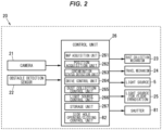
- Figs. 1A and 1B are perspective views showing a floor vacuum cleaner in an embodiment of the invention, and Fig. 2 is a functional block diagram thereof.
- Fig. 3A is a plan view showing the floor vacuum cleaner, and
- Fig. 3B is a schematic diagram illustrating a cross-sectional structure thereof.
- a floor vacuum cleaner 1 includes a main body 2 having a suction port 3 provided on a bottom surface 20a to suck in dirt and dust, a dust box 4 to store dirt and dust sucked in through the suction port 3, and a light source 5 to irradiate the inside of the dust box 4 with ultraviolet light to inactivate bacteria and viruses in the dust box 4.
- the main body 2 corresponds to a self-propelled floor vacuum cleaner main body 20 having a travel mechanism 24 allowing for self-propulsion.
- the floor vacuum cleaner main body 20, which is the main body 2 includes a camera 21, an obstacle detection sensor 22, a dust collection mechanism 23, the travel mechanism 24, the light source 5, a control unit 26, and a case 27 that houses these components.
- the invention is not limited thereto and can also be applied to floor vacuum cleaners which are moved manually, such as a hand-supported type.
- a main body having the dust box 4 may be provided separately from the main body 2. This point will be described later.
- the camera 21 is to capture images of the surroundings of the floor vacuum cleaner main body 20 and is used to acquire, e.g., a floor map (described later) or to acquire the position of the floor vacuum cleaner main body 20.
- the floor vacuum cleaner main body 20 may be provided with plural cameras 21, and may be configured to capture images of the surroundings of the floor vacuum cleaner main body 20 with the plural cameras 21.
- the camera 21 is not shown in Figs. 1A, 1B , 3A and 3B .
- the obstacle detection sensor 22 is to detect whether or not an obstacle is present near the floor vacuum cleaner main body 20, so that collision of the floor vacuum cleaner main body 20 with the obstacle can be suppressed.
- an infrared sensor or an ultrasonic sensor can be used as the obstacle detection sensor 22.
- the obstacle detection sensor 22 is not shown in Figs. 1A, 1B , 3A and 3B .
- the floor vacuum cleaner main body 20 may include various sensors other than the obstacle detection sensor 22, and may include, e.g., a gyroscope sensor that detects a rotation angle when the floor vacuum cleaner main body 20 travels, a travel sensor that detects a travelled distance of the floor vacuum cleaner main body 20, a floor distance sensor that detects level differences, etc. by detecting the distance between the floor vacuum cleaner main body unit 20 and the floor, and a particle sensor that detects the amount of dirt and dust, etc. sucked in through the suction port 3.
- a gyroscope sensor that detects a rotation angle when the floor vacuum cleaner main body 20 travels
- a travel sensor that detects a travelled distance of the floor vacuum cleaner main body 20
- a floor distance sensor that detects level differences, etc. by detecting the distance between the floor vacuum cleaner main body unit 20 and the floor
- a particle sensor that detects the amount of dirt and dust, etc. sucked in through the suction port 3.
- the dust collection mechanism 23 is a mechanism to suck in dirt and dust on the floor and collect the dirt and dust into the floor vacuum cleaner main body 20, and has a rotating brush 23a rotatably provided at the suction port 3 which opens on the bottom surface 20a of the floor vacuum cleaner main body 20 toward the floor (i.e. opens downward), a brush drive unit (not shown) to scrape off dirt from the floor by rotationally driving the rotating brush 23a, a fan 23b (see Fig. 3B ) which serves as a suction member to suck in dirt and dust through the suction port 3, and the dust box 4 (see Fig. 3B ) to store the dirt and dust, etc. sucked in through the suction port 3.
- the dust collection mechanism 23 also has a side brush 23c that is provided on the bottom surface 20a of the floor vacuum cleaner main body 20 so as to protrude from the floor vacuum cleaner main body 20 and is driven to rotate about a rotation axis substantially perpendicular to the floor (i.e., substantially along the vertical direction).
- the side brush 23c serves to sweep out dirt and dust from the corners of the room where the rotating brush 23a cannot reach, and to guide the dirt and dust to the suction port 3.
- the side brush 23c is provided so as to protrude outside from the floor vacuum cleaner main body 20 in plan view (i.e., when viewed from above).
- the travel mechanism 24 is a mechanism to make the floor vacuum cleaner main body 20 travel or self-propel, and has wheels 24a (see Fig. 1B ) provided on the bottom surface 20a of the floor vacuum cleaner main body 20, and a motor (not shown) to drive the wheels 24a.
- wheels 24a see Fig. 1B
- a motor not shown
- the case where two wheels 24a are arranged opposite to each other so that their rotation axes are aligned in a straight line is shown here, but the number and arrangement of the wheels 24a are not particularly limited.
- the light source 5 serves to irradiate the inside of the dust box 4 with ultraviolet light and thereby inactivate bacteria and viruses sucked into the dust box 4.
- the light source 5 is composed of light-emitting diodes 51 that emit ultraviolet light.
- an ultraviolet lamp can be used as the light source 5, but many of ultraviolet lamps use mercury and this poses a safety problem in the event of being damaged.
- ultraviolet light lamps emit not only ultraviolet light with a wavelength suitable for inactivating bacteria, etc. but also light in a very wide range of wavelengths including infrared light, it is wasteful and power consumption is also high.
- infrared may heat and scorch the floor.
- the light-emitting diode 51 as the light source 5 as in the present embodiment, it is possible to ensure safety in the event of being damaged, keep power consumption down, and suppress problems such as scorching of the floor. Furthermore, the start-up time of ultraviolet lamps is long at the beginning of irradiation with ultraviolet light, but it is possible to reduce the start-up time at the beginning of irradiation with ultraviolet light by using the light-emitting diodes 51.
- the light-emitting diode 51 used for the light source 5 it is desirable to use the light-emitting diode 51 that emits deep ultraviolet light which is highly effective in inactivating bacteria, etc.
- the light-emitting diode 51 used for the light source 5 the light-emitting diode 51 which emits deep ultraviolet light with a wavelength of not less than 250 nm and not more than 280 nm may be used.
- the number of light-emitting diodes 51 used as the light source 5 is not limited thereto and can be changed as appropriate according to the size, etc. of the dust box 4.
- the light source 5 is arranged below the dust box 4 on the outside of the dust box 4 so as to emit ultraviolet light upward from below. Therefore, the dust box 4 is preferably made of a material transparent to ultraviolet light. In this regard, however, the dust box 4 when made of, e.g., quartz glass may break by impact, etc., hence, it is more desirable that the dust box 4 be made of a resin transparent to ultraviolet light.
- a fluorine-based resin composition can be used as the resin transparent to ultraviolet light.
- the dust box 4 does not need to be entirely made of a material transparent to ultraviolet light.
- the dust box 4 may be configured such that only at least the surface on the light source 5 side (i.e., the bottom surface) is made of a material transparent to ultraviolet light, or the dust box 4 may be configured such that a window made of a material transparent to ultraviolet light is provided on the surface on the light source 5 side (i.e., the bottom surface) and ultraviolet light is emitted into the dust box 4 through the window. It is more desirable that the light source 5 be positioned so as to emit ultraviolet light toward the upper corners of the dust box 4 since the airflow tends to stagnate at the upper corners of the dust box 4.
- the light source 5 may be intermittently driven so as to repeatedly turn on and off at predetermined time intervals. This reduces the time for driving the light source 5, thereby suppressing degradation of the light source 5 and reducing power consumption. In addition, degradation of the dust box 4 can be suppressed and the service life of the floor vacuum cleaner 1 can be improved.
- the floor vacuum cleaner 1 further includes light sources 25 for floor irradiation to irradiate the floor with ultraviolet light.
- the light source 25 for floor irradiation serves to irradiate the floor with ultraviolet light and thereby inactivate bacteria or viruses present on the floor.
- the light source 25 for floor irradiation is composed of a light-emitting diode that emits deep ultraviolet light with a wavelength of not less than 250 nm and not more than 280 nm, in the same manner as the light source 5.
- the light sources 25 for floor irradiation are provided on the bottom surface 20a of the floor vacuum cleaner main body 20 so as to face the floor.
- the control unit 26 controls the dust collection mechanism 23 and the travel mechanism 24 based on information from the camera 21 or the obstacle detection sensor 22, also controls the light source 5, etc. and is realized by appropriately combining an arithmetic element, a memory, interface, software and a storage device, etc.
- the control unit 26 has a map acquisition unit 261, a position acquisition unit 262, a contamination status detection unit 263, a drive control unit 264, a dust collection control unit 265, a light source control unit 266, and a storage unit 267.
- the map acquisition unit 261 performs a test run at the time of cleaning for the first time, performs mapping of the floor to be cleaned, and acquires a floor map. Since various methods for test run and mapping process are known and public knowledge, the description thereof will be omitted here.
- the map acquisition unit 261 stores the acquired floor map in the storage unit 267.
- the position acquisition unit 262 acquires position information indicating where in the floor map the floor vacuum cleaner main body 20 is located.
- the position acquisition unit 262 acquires the position information of the floor vacuum cleaner main body 20 (i.e., position coordinates in the floor map) based on, e.g., images obtained from the camera 21 or information from a gyroscope sensor or a travel sensor, etc.
- the contamination status detection unit 263 detects the contamination status of the floor to be cleaned.
- the contamination status detection unit 263 detects the contamination status of the floor based on, e.g., the dust collection amount detected by a particle sensor.
- the contamination status detection unit 263 can be configured to detect the contamination status of the floor based on the travel speed or the suction strength level.
- the drive control unit 264 make the floor vacuum cleaner main body 20 travel by controlling the drive of the travel mechanism 24.
- the drive control unit 264 sets a route so that the cleaner travels thoroughly within the set cleaning area, and causes the floor vacuum cleaner main body 20 to travel along the set route.
- the drive control unit 264 performs drive control so that the floor vacuum cleaner main body 20 does not collide with an obstacle, etc.
- the drive control unit 264 may be configured to be capable of changing the travel speed according to the dust collection amount. It is possible to collect dust efficiently, e.g., by decreasing the travel speed in case of a large dust collection amount and increasing the travel speed in case of a small dust collection amount.
- the dust collection control unit 265 controls the dust collection mechanism 23.
- the dust collection mechanism 23 may be configured to be capable of changing the suction strength level according to the dust collection amount. For example, by increasing the suction strength level in case of a large dust collection amount and decreasing the suction strength level in case of a small dust collection amount, it is possible to suppress power consumption and collect dust efficiently.
- the suction strength level can be adjusted, e.g., by increasing or decreasing the rotation speed of the fan 23b.
- the light source control unit 266 performs drive control of the light source 5 and the light sources 25 for floor irradiation.
- the light source control unit 266 may control so that the light source 5 and the light sources 25 for floor irradiation are continuously on, or so that light source 5 and the light sources 25 for floor irradiation blink (i.e., repeat on and off alternately).
- the light source control unit 266 may also control the emission intensity of ultraviolet light from the light source 5 according to the dust collection amount.
- the light source control unit 266 may control the emission intensity of ultraviolet light from the light sources 25 for floor irradiation according to the material of the floor and the contamination status of the floor.
- the emission intensity of the ultraviolet light from the light source 5 and the light sources 25 for floor irradiation can be controlled by the magnitude of the drive current.
- the emission intensity of the ultraviolet light can also be controlled by blinking time intervals or the ratio of the lighting time and the blinking time.
- the storage unit 267 stores the floor map acquired by the map acquisition unit 261 and the contamination status of the floor detected by the contamination status detection unit 263, etc.
- the floor vacuum cleaner 1 may be configured so that floor material setting can be made.
- the floor material setting may be made by user input, or an appropriate sensor capable of identifying the material of the floor (e.g., a floor detection sensor using the intensity of reflected light when emitting light onto the floor or using distortion of the wheels 24a, etc.) may be provided on the floor vacuum cleaner main body 20 to automatically identify the material of the floor.
- the floor vacuum cleaner 1 in the present embodiment includes not less than one side hole 6 that sucks in dirt and dust stirred up around the floor vacuum cleaner main body 20 and guides the dirt and dust to the dust box 4.
- the side holes 6 are provided on the floor vacuum cleaner main body 20 and serve to suck in dirt and dust stirred up by the travel of the floor vacuum cleaner main body 20 or the morion of the side brush 23c and thereby suppress scattering of dirt and dust near the floor to the surroundings. For example, floors in hospitals, etc. are at relatively high risk of microbiological contamination.
- the side holes 6 be provided so as to open at least in the vicinity of the side brush 23c. In more particular, it is desirable that at least one of the side holes 6 be provided so as to open above the driving range of the side brush 23c indicated by the dash-dot line A in Fig. 3A .
- the floor vacuum cleaner main body 20 is formed in a substantially cylindrical shape, and plural side holes 6 are provided on a side surface (i.e., the circumferential side surface) of the floor vacuum cleaner main body 20 at substantially equal intervals. Then, each side hole 6 is provided so as to open toward the side of the floor vacuum cleaner main body 20.
- the configuration of the side hole 6 is not limited thereto as long as it is possible to suck in dirt and dust stirred up around the floor vacuum cleaner main body 20.
- the side holes 6 may be formed so as to open diagonally downward or facing downward.
- the floor vacuum cleaner 1 is configured so that suction through the suction port 3 and suction through each side hole 6 are performed by the fan 23b which is the common suction member. Air and dirt and dust sucked in through the suction port 3 and the side holes 6 are introduced into the dust box 4, and the dirt and dust are trapped and collected by a filter 41 provided at the outlet of the dust box 4.
- a photocatalytic filter can be used as the filter 41. In this case, it is possible to break organic matters (i.e., malodorous components) in the exhaust air down and to deodorize by activating the photocatalyst with ultraviolet light from the light source 5.
- the filter 41 may be composed of plural filters including one photocatalytic filter.
- Exhaust air which has passed through filter 41 passes through the fan 23b and is discharged from an exhaust port 7 to the outside of the floor vacuum cleaner main body 20.
- the exhaust port 7 is provided at the center of the floor vacuum cleaner main body 20 in plan view so that the air is exhausted upward (i.e., upward in the vertical direction, or in a direction perpendicular to the floor). This suppresses stirring-up of dirt and dust on the floor by the exhaust air, and it is thereby possible to further reduce the risk of infection spreading due to microbiological contamination, etc., of the floor.
- the floor vacuum cleaner 1 also includes the side hole opening/closing mechanism 8 that controls opening and closing of the side holes 6.
- the side hole opening/closing mechanism 8 has shutters 81 (see Fig. 3B ) capable of opening and closing the side holes 6, and a side hole opening/closing control unit 82 (see Fig. 2 ) that controls opening and closing of the side holes 6 by driving the shutters 81.
- the mechanism to open and close the side hole 6 is not limited to the shutter 81 and may be another mechanism such as solenoid valve.
- the side hole opening/closing control unit 82 is mounted on the control unit 26 and controls the suction power at the suction port 3 and the suction power at the side holes 6 by controlling opening and closing of the side holes 6.
- the side hole opening/closing control unit 82 is configured to control opening and closing of the side holes 6 according to the operation mode set by the user.
- the side hole opening/closing control unit 82 fully closes the side holes 6 by the shutters 81. This maximizes the suction power at the suction port 3, which increases cleaning efficiency.
- the side hole opening/closing control unit 82 fully opens the side holes 6 by retracting the shutters 81.
- the side hole opening/closing control unit 82 may be configured to adjust the degree of opening or closing of the side holes 6 according to the travel speed of the floor vacuum cleaner main body 20, the material of the floor, or the dust collection amount, etc. For example, it may be configured such that when the travel speed of the floor vacuum cleaner main body 20 is faster, the side holes 6 are opened more since more microorganisms, etc., are stirred up from the floor. In addition, it may be configured such that side holes 6 are closed more when the material of the floor is softer.
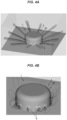
- the present inventors performed simulations to verify the effect of forming the side holes 6. First, how the behavior of dirt and dust changes by suction through the side holes 6 was examined for the case where dirt and dust are radially stirred up from the floor vacuum cleaner main body 20 as shown in Fig. 4A . The simulation was performed using airflow analysis software. The result of the simulation is shown in Fig. 4B . As shown in Fig. 4B , it was confirmed that dirt and dust were sucked into the side holes 6 by suction through the side holes 6 and scattering of the dirt and dust to the surroundings was suppressed.
- the floor vacuum cleaner 1 in the present embodiment includes the light source 5 to irradiate the inside of the dust box 4 with ultraviolet light to inactivate bacteria and viruses in the dust box 4, and not less than one side hole 6 being provided on the floor vacuum cleaner main body 20 separately from the suction port 3, sucking in dirt and dust stirred up around the floor vacuum cleaner main body 20 and guiding the dirt and dust to the dust box 4.
- dirt and dust stirred up around the floor vacuum cleaner main body 20 can be sucked in through the side holes 6 and the air can be exhausted after inactivating bacteria or viruses using the light source 5.
- scattering of dirt and dust containing bacteria or viruses to the surroundings is suppressed, and even when cleaning floors in hospitals, etc., it is possible to reduce the risk of infection spreading due to microbiological contamination, etc., of the floor.
- the light source 5 in the above embodiment is configured to emit ultraviolet light upward from below the dust box 4, but the light source 5 may further include upper-side light-emitting diodes 52 that emit ultraviolet light downward from above as shown in Fig. 6A .
- the upper-side light-emitting diodes 52 are arranged so as to emit ultraviolet light obliquely downward from the upper corners of the dust box 4 toward the center of the dust box 4.
- the arrangement of the upper-side light-emitting diodes 52 is not limited thereto. The effect of inactivating bacteria or viruses can be obtained sufficiently by having the upper-side light-emitting diodes 52 even if debris accumulates at the lower portion of the dust box 4 and blocks the ultraviolet light emitted upward from below.
- a reflector 53 which reflects part of the emitted ultraviolet light and is transparent to the rest of the light, may be provided between the lower-side light-emitting diodes 51 and the dust box 4 as shown in Fig. 6B .
- the light source 5 can also serve as a light source for floor irradiation and the light sources 25 for floor irradiation can thus be omitted.
- the reflector 53 may be configured to be retractable from above the lower-side light-emitting diodes 51 or to be detachable, so that irradiating or not irradiating the floor with ultraviolet light can be selected by the presence or absence of the reflector 53. Advancing and retreating of the reflector 53 to and from above the light-emitting diodes 51, or attaching and detaching of the reflector 53, may be performed automatically or may be performed manually.
- the invention is also applicable to non-self-propelled floor vacuum cleaners.
- the invention can also be applied to, e.g., a hand-supported floor vacuum cleaner 1 that has the main body 2, a handle 91, and a connecting portion 9 that connects the main body 2 and the handle 91, as shown in Fig. 7 .
- the dust box 4 is provided in the connecting portion 9 in the illustrated example, but the dust box 4 may be provided in the main body 2.
- the side holes 6 are to suck in dirt and dust stirred up from the floor and thus need to be formed separately from the suction port 3 provided to suck in dirt and dust on the floor and need to be formed at a distance from the floor.
- the suction port 3 partially opens to the side in a cutout manner, and such a cutout on the side is part of the suction port 3 and is different from the side hole 6 provided to suck in dirt and dust stirred up from the floor.
Landscapes
- Physics & Mathematics (AREA)
- Engineering & Computer Science (AREA)
- Plasma & Fusion (AREA)
- Electric Vacuum Cleaner (AREA)
Abstract
Description
- The present invention relates to a floor vacuum cleaner.
- A self-propelled floor vacuum cleaner that self-propels and cleans indoor spaces is known (see, e.g., Patent Literature 1). The self-propelled floor vacuum cleaner has a side brush provided on a bottom surface of a vacuum cleaner main body to sweep out dirt and dust from corners, etc. of a room out of reach of a suction opening and guide the dirt and dust to the suction opening. The side brush is provided so as to protrude outward from the vacuum cleaner main body in plan view, has a rotation axis in a substantially up-and-down direction (i.e., a direction substantially along the vertical direction during cleaning), and is driven to rotate about the rotation axis.
- Patent Literature 1:
JP 2019-162542A - By the way, floors in hospitals, etc., are at relatively high risk of microbiological contamination since there may be a case where, e.g., disposal of vomit from infected patients is not sufficient. Therefore, when cleaning floors in hospitals, etc., it is required to reduce the risk of infection spreading due to microbiological contamination, etc., of the floor.
- For example, in case of the self-propelled floor vacuum cleaner described above, dirt and dust on the floor are stirred up as the vacuum cleaner main body travels or the side brush is driven, which may increase the risk of infection spreading due to microbiological contamination, etc., of the floor. Also in case of a hand-supported floor vacuum cleaner, dirt and dust on the floor is inevitably stirred up during cleaning, and measures are needed.
- Therefore, it is an object of the invention to provide a floor vacuum cleaner that can reduce the risk of infection spreading due to dirt and dust on the floor being stirred up.
- A floor vacuum cleaner in an embodiment of the invention comprises:
- a main body comprising a suction port provided on a bottom surface to suck in dirt and dust;
- a dust box to store dirt and dust sucked in through the suction port;
- a light source to irradiate the inside of the dust box with ultraviolet light to inactivate bacteria and viruses in the dust box; and
- not less than one side hole being provided on the main body separately from the suction port, sucking in dirt and dust stirred up around the main body, and guiding the dirt and dust to the dust box.
- According to the invention, it is possible to provide a floor vacuum cleaner that can reduce the risk of infection spreading due to dirt and dust on the floor being stirred up.
-
-
Fig. 1A is a perspective view showing a floor vacuum cleaner in an embodiment of the present invention. -
Fig. 1B is a perspective view showing the floor vacuum cleaner in the embodiment of the invention. -
Fig. 2 is a functional block diagram illustrating the floor vacuum cleaner. -
Fig. 3A is a plan view showing the floor vacuum cleaner. -
Fig. 3B is a schematic diagram illustrating a cross-sectional structure of the floor vacuum cleaner. -
Fig. 4A is an explanatory diagram illustrating a result of a simulation to verify the effect of a side hole. -
Fig. 4B is an explanatory diagram illustrating a result of a simulation to verify the effect of the side hole. -
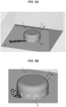
Fig. 5A is an explanatory diagram illustrating a result of a simulation to verify the effect of the side hole. -
Fig. 5B is an explanatory diagram illustrating a result of a simulation to verify the effect of the side hole. -
Fig. 6A is a schematic diagram illustrating a cross-sectional structure of the floor vacuum cleaner in a modification of the invention. -
Fig. 6B is a schematic diagram illustrating a cross-sectional structure of the floor vacuum cleaner in a modification of the invention. -
Fig. 7 is a schematic diagram illustrating the floor vacuum cleaner in a modification of the invention. - An embodiment of the invention will be described below in conjunction with the appended drawings.
-
Figs. 1A and 1B are perspective views showing a floor vacuum cleaner in an embodiment of the invention, andFig. 2 is a functional block diagram thereof.Fig. 3A is a plan view showing the floor vacuum cleaner, andFig. 3B is a schematic diagram illustrating a cross-sectional structure thereof. - As shown in
Figs. 1A, 1B ,2 ,3A and 3B , afloor vacuum cleaner 1 includes amain body 2 having asuction port 3 provided on abottom surface 20a to suck in dirt and dust, adust box 4 to store dirt and dust sucked in through thesuction port 3, and alight source 5 to irradiate the inside of thedust box 4 with ultraviolet light to inactivate bacteria and viruses in thedust box 4. - A case where the
floor vacuum cleaner 1 is a self-propelled floor vacuum cleaner will be described in the present embodiment. In this case, themain body 2 corresponds to a self-propelled floor vacuum cleanermain body 20 having atravel mechanism 24 allowing for self-propulsion. The floor vacuum cleanermain body 20, which is themain body 2, includes acamera 21, anobstacle detection sensor 22, adust collection mechanism 23, thetravel mechanism 24, thelight source 5, acontrol unit 26, and acase 27 that houses these components. However, the invention is not limited thereto and can also be applied to floor vacuum cleaners which are moved manually, such as a hand-supported type. In this case, a main body having thedust box 4 may be provided separately from themain body 2. This point will be described later. - The
camera 21 is to capture images of the surroundings of the floor vacuum cleanermain body 20 and is used to acquire, e.g., a floor map (described later) or to acquire the position of the floor vacuum cleanermain body 20. The floor vacuum cleanermain body 20 may be provided withplural cameras 21, and may be configured to capture images of the surroundings of the floor vacuum cleanermain body 20 with theplural cameras 21. Thecamera 21 is not shown inFigs. 1A, 1B ,3A and 3B . - The
obstacle detection sensor 22 is to detect whether or not an obstacle is present near the floor vacuum cleanermain body 20, so that collision of the floor vacuum cleanermain body 20 with the obstacle can be suppressed. For example, an infrared sensor or an ultrasonic sensor can be used as theobstacle detection sensor 22. Theobstacle detection sensor 22 is not shown inFigs. 1A, 1B ,3A and 3B . - Although not shown in the drawings, the floor vacuum cleaner
main body 20 may include various sensors other than theobstacle detection sensor 22, and may include, e.g., a gyroscope sensor that detects a rotation angle when the floor vacuum cleanermain body 20 travels, a travel sensor that detects a travelled distance of the floor vacuum cleanermain body 20, a floor distance sensor that detects level differences, etc. by detecting the distance between the floor vacuum cleanermain body unit 20 and the floor, and a particle sensor that detects the amount of dirt and dust, etc. sucked in through thesuction port 3. - The
dust collection mechanism 23 is a mechanism to suck in dirt and dust on the floor and collect the dirt and dust into the floor vacuum cleanermain body 20, and has arotating brush 23a rotatably provided at thesuction port 3 which opens on thebottom surface 20a of the floor vacuum cleanermain body 20 toward the floor (i.e. opens downward), a brush drive unit (not shown) to scrape off dirt from the floor by rotationally driving therotating brush 23a, afan 23b (seeFig. 3B ) which serves as a suction member to suck in dirt and dust through thesuction port 3, and the dust box 4 (seeFig. 3B ) to store the dirt and dust, etc. sucked in through thesuction port 3. - The
dust collection mechanism 23 also has aside brush 23c that is provided on thebottom surface 20a of the floor vacuum cleanermain body 20 so as to protrude from the floor vacuum cleanermain body 20 and is driven to rotate about a rotation axis substantially perpendicular to the floor (i.e., substantially along the vertical direction). Theside brush 23c serves to sweep out dirt and dust from the corners of the room where therotating brush 23a cannot reach, and to guide the dirt and dust to thesuction port 3. As shown inFig. 3A , theside brush 23c is provided so as to protrude outside from the floor vacuum cleanermain body 20 in plan view (i.e., when viewed from above). - The
travel mechanism 24 is a mechanism to make the floor vacuum cleanermain body 20 travel or self-propel, and haswheels 24a (seeFig. 1B ) provided on thebottom surface 20a of the floor vacuum cleanermain body 20, and a motor (not shown) to drive thewheels 24a. The case where twowheels 24a are arranged opposite to each other so that their rotation axes are aligned in a straight line is shown here, but the number and arrangement of thewheels 24a are not particularly limited. - The
light source 5 serves to irradiate the inside of thedust box 4 with ultraviolet light and thereby inactivate bacteria and viruses sucked into thedust box 4. In the present embodiment, thelight source 5 is composed of light-emittingdiodes 51 that emit ultraviolet light. For example, an ultraviolet lamp can be used as thelight source 5, but many of ultraviolet lamps use mercury and this poses a safety problem in the event of being damaged. In addition, since ultraviolet light lamps emit not only ultraviolet light with a wavelength suitable for inactivating bacteria, etc. but also light in a very wide range of wavelengths including infrared light, it is wasteful and power consumption is also high. In addition, if the output is increased, infrared may heat and scorch the floor. By using the light-emittingdiode 51 as thelight source 5 as in the present embodiment, it is possible to ensure safety in the event of being damaged, keep power consumption down, and suppress problems such as scorching of the floor. Furthermore, the start-up time of ultraviolet lamps is long at the beginning of irradiation with ultraviolet light, but it is possible to reduce the start-up time at the beginning of irradiation with ultraviolet light by using the light-emittingdiodes 51. - As the light-emitting
diode 51 used for thelight source 5, it is desirable to use the light-emittingdiode 51 that emits deep ultraviolet light which is highly effective in inactivating bacteria, etc. In more particular, as the light-emittingdiode 51 used for thelight source 5, the light-emittingdiode 51 which emits deep ultraviolet light with a wavelength of not less than 250 nm and not more than 280 nm may be used. Although three light-emittingdiodes 51 are used in the present embodiment, the number of light-emittingdiodes 51 used as thelight source 5 is not limited thereto and can be changed as appropriate according to the size, etc. of thedust box 4. - In the present embodiment, the
light source 5 is arranged below thedust box 4 on the outside of thedust box 4 so as to emit ultraviolet light upward from below. Therefore, thedust box 4 is preferably made of a material transparent to ultraviolet light. In this regard, however, thedust box 4 when made of, e.g., quartz glass may break by impact, etc., hence, it is more desirable that thedust box 4 be made of a resin transparent to ultraviolet light. For example, a fluorine-based resin composition can be used as the resin transparent to ultraviolet light. In addition, to suppress degradation caused by ultraviolet light emitted from thelight source 5, it is possible to use thedust box 4 made of a resin composition containing an anti-UV agent. In this regard, thedust box 4 does not need to be entirely made of a material transparent to ultraviolet light. Thedust box 4 may be configured such that only at least the surface on thelight source 5 side (i.e., the bottom surface) is made of a material transparent to ultraviolet light, or thedust box 4 may be configured such that a window made of a material transparent to ultraviolet light is provided on the surface on thelight source 5 side (i.e., the bottom surface) and ultraviolet light is emitted into thedust box 4 through the window. It is more desirable that thelight source 5 be positioned so as to emit ultraviolet light toward the upper corners of thedust box 4 since the airflow tends to stagnate at the upper corners of thedust box 4. - The
light source 5 may be intermittently driven so as to repeatedly turn on and off at predetermined time intervals. This reduces the time for driving thelight source 5, thereby suppressing degradation of thelight source 5 and reducing power consumption. In addition, degradation of thedust box 4 can be suppressed and the service life of thefloor vacuum cleaner 1 can be improved. - In the present embodiment, the
floor vacuum cleaner 1 further includeslight sources 25 for floor irradiation to irradiate the floor with ultraviolet light. Thelight source 25 for floor irradiation serves to irradiate the floor with ultraviolet light and thereby inactivate bacteria or viruses present on the floor. In the present embodiment, thelight source 25 for floor irradiation is composed of a light-emitting diode that emits deep ultraviolet light with a wavelength of not less than 250 nm and not more than 280 nm, in the same manner as thelight source 5. Thelight sources 25 for floor irradiation are provided on thebottom surface 20a of the floor vacuum cleanermain body 20 so as to face the floor. The case where twolight sources 25 for floor irradiation are arranged so as to sandwich theside brush 23c is shown in the present embodiment, but the number and arrangement of thelight sources 25 for floor irradiation can be changed as appropriate. Moreover, thelight source 25 for floor irradiations do not need to be included. - The
control unit 26 controls thedust collection mechanism 23 and thetravel mechanism 24 based on information from thecamera 21 or theobstacle detection sensor 22, also controls thelight source 5, etc. and is realized by appropriately combining an arithmetic element, a memory, interface, software and a storage device, etc. Thecontrol unit 26 has amap acquisition unit 261, aposition acquisition unit 262, a contaminationstatus detection unit 263, adrive control unit 264, a dustcollection control unit 265, a lightsource control unit 266, and astorage unit 267. - The
map acquisition unit 261 performs a test run at the time of cleaning for the first time, performs mapping of the floor to be cleaned, and acquires a floor map. Since various methods for test run and mapping process are known and public knowledge, the description thereof will be omitted here. Themap acquisition unit 261 stores the acquired floor map in thestorage unit 267. - The
position acquisition unit 262 acquires position information indicating where in the floor map the floor vacuum cleanermain body 20 is located. Theposition acquisition unit 262 acquires the position information of the floor vacuum cleaner main body 20 (i.e., position coordinates in the floor map) based on, e.g., images obtained from thecamera 21 or information from a gyroscope sensor or a travel sensor, etc. - The contamination
status detection unit 263 detects the contamination status of the floor to be cleaned. The contaminationstatus detection unit 263 detects the contamination status of the floor based on, e.g., the dust collection amount detected by a particle sensor. When thedrive control unit 264 or the dust collection control unit 265 (both described later) is configured to be capable of changing the travel speed or the suction strength level according to the dust collection amount, the contaminationstatus detection unit 263 can be configured to detect the contamination status of the floor based on the travel speed or the suction strength level. - The
drive control unit 264 make the floor vacuum cleanermain body 20 travel by controlling the drive of thetravel mechanism 24. Thedrive control unit 264 sets a route so that the cleaner travels thoroughly within the set cleaning area, and causes the floor vacuum cleanermain body 20 to travel along the set route. In addition, using theobstacle detection sensor 22, etc., thedrive control unit 264 performs drive control so that the floor vacuum cleanermain body 20 does not collide with an obstacle, etc. Thedrive control unit 264 may be configured to be capable of changing the travel speed according to the dust collection amount. It is possible to collect dust efficiently, e.g., by decreasing the travel speed in case of a large dust collection amount and increasing the travel speed in case of a small dust collection amount. - The dust
collection control unit 265 controls thedust collection mechanism 23. Thedust collection mechanism 23 may be configured to be capable of changing the suction strength level according to the dust collection amount. For example, by increasing the suction strength level in case of a large dust collection amount and decreasing the suction strength level in case of a small dust collection amount, it is possible to suppress power consumption and collect dust efficiently. The suction strength level can be adjusted, e.g., by increasing or decreasing the rotation speed of thefan 23b. - The light
source control unit 266 performs drive control of thelight source 5 and thelight sources 25 for floor irradiation. The lightsource control unit 266 may control so that thelight source 5 and thelight sources 25 for floor irradiation are continuously on, or so thatlight source 5 and thelight sources 25 for floor irradiation blink (i.e., repeat on and off alternately). The lightsource control unit 266 may also control the emission intensity of ultraviolet light from thelight source 5 according to the dust collection amount. Furthermore, the lightsource control unit 266 may control the emission intensity of ultraviolet light from thelight sources 25 for floor irradiation according to the material of the floor and the contamination status of the floor. The emission intensity of the ultraviolet light from thelight source 5 and thelight sources 25 for floor irradiation can be controlled by the magnitude of the drive current. In case of blinking thelight source 5 and thelight sources 25 for floor irradiation, the emission intensity of the ultraviolet light can also be controlled by blinking time intervals or the ratio of the lighting time and the blinking time. - The
storage unit 267 stores the floor map acquired by themap acquisition unit 261 and the contamination status of the floor detected by the contaminationstatus detection unit 263, etc. Although not shown in the drawings, thefloor vacuum cleaner 1 may be configured so that floor material setting can be made. The floor material setting may be made by user input, or an appropriate sensor capable of identifying the material of the floor (e.g., a floor detection sensor using the intensity of reflected light when emitting light onto the floor or using distortion of thewheels 24a, etc.) may be provided on the floor vacuum cleanermain body 20 to automatically identify the material of the floor. - The
floor vacuum cleaner 1 in the present embodiment includes not less than oneside hole 6 that sucks in dirt and dust stirred up around the floor vacuum cleanermain body 20 and guides the dirt and dust to thedust box 4. As shown inFig. 1A , the side holes 6 are provided on the floor vacuum cleanermain body 20 and serve to suck in dirt and dust stirred up by the travel of the floor vacuum cleanermain body 20 or the morion of theside brush 23c and thereby suppress scattering of dirt and dust near the floor to the surroundings. For example, floors in hospitals, etc. are at relatively high risk of microbiological contamination. However, even when cleaning floors in hospitals, etc., it is possible to reduce the risk of infection spreading due to microbiological contamination, etc., of the floor since providing the side holes 6 on the floor vacuum cleanermain body 20 suppresses stirring-up and scattering of dirt and dust to the surroundings. - When using the self-propelled
floor vacuum cleaner 1, dirt and dust are likely to be stirred up by the motion of theside brush 23c. Therefore, it is desirable that the side holes 6 be provided so as to open at least in the vicinity of theside brush 23c. In more particular, it is desirable that at least one of the side holes 6 be provided so as to open above the driving range of theside brush 23c indicated by the dash-dot line A inFig. 3A . - In the present embodiment, the floor vacuum cleaner
main body 20 is formed in a substantially cylindrical shape, and plural side holes 6 are provided on a side surface (i.e., the circumferential side surface) of the floor vacuum cleanermain body 20 at substantially equal intervals. Then, eachside hole 6 is provided so as to open toward the side of the floor vacuum cleanermain body 20. This makes it possible to efficiently suck in dirt and dust stirred up around the floor vacuum cleanermain body 20. However, the configuration of theside hole 6 is not limited thereto as long as it is possible to suck in dirt and dust stirred up around the floor vacuum cleanermain body 20. For example, the side holes 6 may be formed so as to open diagonally downward or facing downward. - As shown in Figh. 3B, the
floor vacuum cleaner 1 is configured so that suction through thesuction port 3 and suction through eachside hole 6 are performed by thefan 23b which is the common suction member. Air and dirt and dust sucked in through thesuction port 3 and the side holes 6 are introduced into thedust box 4, and the dirt and dust are trapped and collected by afilter 41 provided at the outlet of thedust box 4. A photocatalytic filter can be used as thefilter 41. In this case, it is possible to break organic matters (i.e., malodorous components) in the exhaust air down and to deodorize by activating the photocatalyst with ultraviolet light from thelight source 5. Thefilter 41 may be composed of plural filters including one photocatalytic filter. - Exhaust air which has passed through
filter 41 passes through thefan 23b and is discharged from anexhaust port 7 to the outside of the floor vacuum cleanermain body 20. In the present embodiment, theexhaust port 7 is provided at the center of the floor vacuum cleanermain body 20 in plan view so that the air is exhausted upward (i.e., upward in the vertical direction, or in a direction perpendicular to the floor). This suppresses stirring-up of dirt and dust on the floor by the exhaust air, and it is thereby possible to further reduce the risk of infection spreading due to microbiological contamination, etc., of the floor. - The
floor vacuum cleaner 1 also includes the side hole opening/closing mechanism 8 that controls opening and closing of the side holes 6. The side hole opening/closing mechanism 8 has shutters 81 (seeFig. 3B ) capable of opening and closing the side holes 6, and a side hole opening/closing control unit 82 (seeFig. 2 ) that controls opening and closing of the side holes 6 by driving theshutters 81. In this regard, the mechanism to open and close theside hole 6 is not limited to theshutter 81 and may be another mechanism such as solenoid valve. The side hole opening/closing control unit 82 is mounted on thecontrol unit 26 and controls the suction power at thesuction port 3 and the suction power at the side holes 6 by controlling opening and closing of the side holes 6. - In the present embodiment, three operating modes, "cleaning mode", "sterilization mode" and "cleaning and sterilization mode", can be set, and the side hole opening/
closing control unit 82 is configured to control opening and closing of the side holes 6 according to the operation mode set by the user. In particular, when the "cleaning mode" is set, the side hole opening/closing control unit 82 fully closes the side holes 6 by theshutters 81. This maximizes the suction power at thesuction port 3, which increases cleaning efficiency. Meanwhile, when the "sterilization mode" is set, the side hole opening/closing control unit 82 fully opens the side holes 6 by retracting theshutters 81. This maximizes the suction power at the side holes 6, which increases efficiency of sucking in dirt and dust stirred up from the floor. As a result, it is possible to significantly reduce the risk of infection spreading due to microbiological contamination, etc., of the floor. Then, when the "cleaning and sterilization mode" is set, the side hole opening/closing control unit 82 half-opens the side holes 6 by advancing theshutters 81 halfway. This makes it possible to maintain both the suction power at thesuction port 3 and the suction power at the side holes 6, and it is possible to reduce the risk of infection spreading due to microbiological contamination, etc., of the floor by sucking in dirt and dust stirred up from the floor while cleaning efficiently to some extent. - In addition, the side hole opening/
closing control unit 82 may be configured to adjust the degree of opening or closing of the side holes 6 according to the travel speed of the floor vacuum cleanermain body 20, the material of the floor, or the dust collection amount, etc. For example, it may be configured such that when the travel speed of the floor vacuum cleanermain body 20 is faster, the side holes 6 are opened more since more microorganisms, etc., are stirred up from the floor. In addition, it may be configured such that side holes 6 are closed more when the material of the floor is softer. - The present inventors performed simulations to verify the effect of forming the side holes 6. First, how the behavior of dirt and dust changes by suction through the side holes 6 was examined for the case where dirt and dust are radially stirred up from the floor vacuum cleaner
main body 20 as shown inFig. 4A . The simulation was performed using airflow analysis software. The result of the simulation is shown inFig. 4B . As shown inFig. 4B , it was confirmed that dirt and dust were sucked into the side holes 6 by suction through the side holes 6 and scattering of the dirt and dust to the surroundings was suppressed. - Similarly, to examine the influence of dirt and dust stirred up by the
side brush 23c, how the behavior of dirt and dust changes by suction through the side holes 6 was examined for the case where dirt and dust are ejected outward from one location near the floor vacuum cleanermain body 20 as shown inFig. 5A . As a result, as shown inFig. 5B , it was confirmed that dirt and dust were sucked into the side holes 6 by suction through the side holes 6 and scattering of dirt and dust to the surroundings was suppressed. These simulation results confirm that scattering of dirt and dust stirred up from the floor to the surroundings can be suppressed by providing the side holes 6. - As described above, the
floor vacuum cleaner 1 in the present embodiment includes thelight source 5 to irradiate the inside of thedust box 4 with ultraviolet light to inactivate bacteria and viruses in thedust box 4, and not less than oneside hole 6 being provided on the floor vacuum cleanermain body 20 separately from thesuction port 3, sucking in dirt and dust stirred up around the floor vacuum cleanermain body 20 and guiding the dirt and dust to thedust box 4. With this configuration, dirt and dust stirred up around the floor vacuum cleanermain body 20 can be sucked in through the side holes 6 and the air can be exhausted after inactivating bacteria or viruses using thelight source 5. As a result, scattering of dirt and dust containing bacteria or viruses to the surroundings is suppressed, and even when cleaning floors in hospitals, etc., it is possible to reduce the risk of infection spreading due to microbiological contamination, etc., of the floor. - The
light source 5 in the above embodiment is configured to emit ultraviolet light upward from below thedust box 4, but thelight source 5 may further include upper-side light-emittingdiodes 52 that emit ultraviolet light downward from above as shown inFig. 6A . In the illustrated example, the upper-side light-emittingdiodes 52 are arranged so as to emit ultraviolet light obliquely downward from the upper corners of thedust box 4 toward the center of thedust box 4. However, the arrangement of the upper-side light-emittingdiodes 52 is not limited thereto. The effect of inactivating bacteria or viruses can be obtained sufficiently by having the upper-side light-emittingdiodes 52 even if debris accumulates at the lower portion of thedust box 4 and blocks the ultraviolet light emitted upward from below. - Furthermore, a
reflector 53, which reflects part of the emitted ultraviolet light and is transparent to the rest of the light, may be provided between the lower-side light-emittingdiodes 51 and thedust box 4 as shown inFig. 6B . As a result, the floor is irradiated with the ultraviolet light reflected by thereflector 53, hence, thelight source 5 can also serve as a light source for floor irradiation and thelight sources 25 for floor irradiation can thus be omitted. In addition, thereflector 53 may be configured to be retractable from above the lower-side light-emittingdiodes 51 or to be detachable, so that irradiating or not irradiating the floor with ultraviolet light can be selected by the presence or absence of thereflector 53. Advancing and retreating of thereflector 53 to and from above the light-emittingdiodes 51, or attaching and detaching of thereflector 53, may be performed automatically or may be performed manually. - In addition, although the self-propelled
floor vacuum cleaner 1 has been described in the above embodiment, the invention is also applicable to non-self-propelled floor vacuum cleaners. The invention can also be applied to, e.g., a hand-supportedfloor vacuum cleaner 1 that has themain body 2, ahandle 91, and a connecting portion 9 that connects themain body 2 and thehandle 91, as shown inFig. 7 . Thedust box 4 is provided in the connecting portion 9 in the illustrated example, but thedust box 4 may be provided in themain body 2. The side holes 6 are to suck in dirt and dust stirred up from the floor and thus need to be formed separately from thesuction port 3 provided to suck in dirt and dust on the floor and need to be formed at a distance from the floor. For example, there may be a case where thesuction port 3 partially opens to the side in a cutout manner, and such a cutout on the side is part of thesuction port 3 and is different from theside hole 6 provided to suck in dirt and dust stirred up from the floor. - Technical ideas understood from the embodiment will be described below citing the reference signs, etc., used for the embodiment. However, each reference sign, etc., described below is not intended to limit the constituent elements in the claims to the members, etc., specifically described in the embodiment.
- (1) A
floor vacuum cleaner 1, comprising: amain body 2 comprising asuction port 3 provided on abottom surface 20a to suck in dirt and dust; adust box 4 to store dirt and dust sucked in through thesuction port 3; alight source 5 to irradiate the inside of thedust box 4 with ultraviolet light to inactivate bacteria and viruses in thedust box 4; and not less than oneside hole 6 being provided on themain body 2 separately from thesuction port 3, sucking in dirt and dust stirred up around themain body 2, and guiding the dirt and dust to thedust box 4. - (2) The
floor vacuum cleaner 1 as defined by (1), comprising; aside brush 23c that is provided on the bottom surface 20c of themain body 2 so as to protrude from themain body 2 and is driven to rotate about a rotation axis perpendicular to a floor, wherein at least one saidside hole 6 is provided so as to open above a driving range A of theside brush 23c. - (3) The
floor vacuum cleaner 1 as defined by (1) or (2), wherein suction through thesuction port 3 and suction through theside hole 6 are performed by a common suction member (23b), and wherein a side hole opening/closing mechanism 8 is provided to control suction power at thesuction port 3 and suction power at theside hole 6 by controlling opening and closing of theside hole 6. - (4) The
floor vacuum cleaner 1 as defined by any one of (1) to (3), wherein theside hole 6 is provided on a side surface of themain body 2 so as to open to the side. - (5) The
floor vacuum cleaner 1 as defined by any one of (1) to (4), wherein thelight source 5 is intermittently driven so as to repeatedly turn on and off at predetermined time intervals. - (6) The
floor vacuum cleaner 1 defined as any one of (1) to (5), further comprising: alight source 25 for floor irradiation that irradiates the floor with ultraviolet light. - (7) The
floor vacuum cleaner 1 as defined by any one of (1) to (6), wherein themain body 2 comprises a self-propelled floor vacuum cleanermain body 20 comprising atravel mechanism 24 allowing for self-propulsion. - (8) The
floor vacuum cleaner 1 as defined by (7), wherein the floor vacuum cleanermain body 20 comprises anexhaust port 7 provided at the center in plan view to exhaust air upward in a direction perpendicular to the floor. - Although the embodiment of the invention has been described, the invention according to claims is not to be limited to the embodiment described above. Further, please note that not all combinations of the features described in the embodiment are necessary to solve the problem of the invention. In addition, the invention can be appropriately modified and implemented without departing from the gist thereof.
-
- 1 floor vacuum cleaner
- 2 main body
- 20 floor vacuum cleaner main body
- 20a bottom surface
- 3 suction port
- 4 dust box
- 5 light source
- 6 side hole
- 7 exhaust port
- 8 side hole opening/closing mechanism
- 23b fan (suction member)
- 23c side brush
Claims (8)
- A floor vacuum cleaner, comprising:a main body comprising a suction port provided on a bottom surface to suck in dirt and dust;a dust box to store dirt and dust sucked in through the suction port;a light source to irradiate the inside of the dust box with ultraviolet light to inactivate bacteria and viruses in the dust box; andnot less than one side hole being provided on the main body separately from the suction port, sucking in dirt and dust stirred up around the main body, and guiding the dirt and dust to the dust box.
- The floor vacuum cleaner according to claim 1, comprising;a side brush that is provided on the bottom surface of the main body so as to protrude from the main body and is driven to rotate about a rotation axis perpendicular to a floor,wherein at least one said side hole is provided so as to open above a driving range of the side brush.
- The floor vacuum cleaner according to claim 1 or 2, wherein suction through the suction port and suction through the side hole are performed by a common suction member, and wherein a side hole opening/closing mechanism is provided to control suction power at the suction port and suction power at the side hole by controlling opening and closing of the side hole.
- The floor vacuum cleaner according to claim 1 or 2, wherein the side hole is provided on a side surface of the main body so as to open to the side.
- The floor vacuum cleaner according to claim 1 or 2, wherein the light source is intermittently driven so as to repeatedly turn on and off at predetermined time intervals.
- The floor vacuum cleaner according to claim 1 or 2, further comprising:
a light source for floor irradiation that irradiates the floor with ultraviolet light. - The floor vacuum cleaner according to claim 1 or 2, wherein the main body comprises a self-propelled floor vacuum cleaner main body comprising travel mechanism allowing for self-propulsion.
- The floor vacuum cleaner according to claim 7, wherein the floor vacuum cleaner main body comprises an exhaust port provided at the center in plan view to exhaust air upward in a direction perpendicular to the floor.
Applications Claiming Priority (2)
| Application Number | Priority Date | Filing Date | Title |
|---|---|---|---|
| JP2022090694A JP7414889B2 (en) | 2022-06-03 | 2022-06-03 | floor vacuum cleaner |
| PCT/JP2023/019640 WO2023234191A1 (en) | 2022-06-03 | 2023-05-26 | Floor vacuum cleaner |
Publications (2)
| Publication Number | Publication Date |
|---|---|
| EP4497364A1 true EP4497364A1 (en) | 2025-01-29 |
| EP4497364A4 EP4497364A4 (en) | 2026-04-01 |
Family
ID=89024939
Family Applications (1)
| Application Number | Title | Priority Date | Filing Date |
|---|---|---|---|
| EP23815948.7A Withdrawn EP4497364A4 (en) | 2022-06-03 | 2023-05-26 | FLOOR VACUUM |
Country Status (4)
| Country | Link |
|---|---|
| EP (1) | EP4497364A4 (en) |
| JP (1) | JP7414889B2 (en) |
| CN (1) | CN119317383A (en) |
| WO (1) | WO2023234191A1 (en) |
Family Cites Families (10)
| Publication number | Priority date | Publication date | Assignee | Title |
|---|---|---|---|---|
| JP2001000370A (en) * | 1999-06-22 | 2001-01-09 | Matsushita Electric Ind Co Ltd | Vacuum cleaner and accessories for vacuum cleaner |
| KR20060032879A (en) * | 2004-10-13 | 2006-04-18 | 엘지전자 주식회사 | Floor sterilization system using robot cleaner |
| KR100603209B1 (en) * | 2005-02-23 | 2006-07-24 | 삼성광주전자 주식회사 | Waste container with ultraviolet transmission window and vacuum cleaner having same |
| KR100812285B1 (en) * | 2006-11-14 | 2008-03-13 | 주식회사 우리기술 | Air Cleaner Robot Cleaner |
| KR100899785B1 (en) * | 2007-09-14 | 2009-05-28 | 주식회사 유라코퍼레이션 | Cleaner with sterilization device |
| TW201705889A (en) * | 2015-08-04 | 2017-02-16 | Massif Co Ltd | Self-propelled device with vacuum cleaning and air purifying functions enabling an air purifier positioned on a self-propelled vacuum cleaner to access a power source from the self-propelled vacuum cleaner |
| JP2017140350A (en) | 2016-02-05 | 2017-08-17 | パナソニックIpマネジメント株式会社 | Autonomous travel-type vacuum cleaner, auxiliary brush for the same and vacuum cleaner system including autonomous travel-type vacuum cleaner |
| JP2021029710A (en) * | 2019-08-27 | 2021-03-01 | パナソニックIpマネジメント株式会社 | Self-propelled vacuum cleaner and cleaning system |
| US20220061608A1 (en) * | 2020-09-03 | 2022-03-03 | Team International Group of America Inc. | Germicidal Floor Cleaner |
| JP2022109461A (en) * | 2021-01-15 | 2022-07-28 | 株式会社日立製作所 | Mobile sterilization device and sterilization method |
-
2022
- 2022-06-03 JP JP2022090694A patent/JP7414889B2/en active Active
-
2023
- 2023-05-26 EP EP23815948.7A patent/EP4497364A4/en not_active Withdrawn
- 2023-05-26 WO PCT/JP2023/019640 patent/WO2023234191A1/en not_active Ceased
- 2023-05-26 CN CN202380044664.5A patent/CN119317383A/en active Pending
Also Published As
| Publication number | Publication date |
|---|---|
| CN119317383A (en) | 2025-01-14 |
| WO2023234191A1 (en) | 2023-12-07 |
| JP2023177813A (en) | 2023-12-14 |
| JP7414889B2 (en) | 2024-01-16 |
| EP4497364A4 (en) | 2026-04-01 |
Similar Documents
| Publication | Publication Date | Title |
|---|---|---|
| JP6395891B2 (en) | Blower | |
| KR100491779B1 (en) | Portable germicidal air filter | |
| JP4840181B2 (en) | Air cleaner | |
| JP6597891B2 (en) | Air cleaner | |
| US11383000B2 (en) | Aerosol sterilization surgical lamp using UV light and visible light | |
| CN114383251A (en) | Indoor air sterilization and purification apparatus using UV-C LED | |
| JP7464508B2 (en) | Robot vacuum cleaner | |
| CN110089980A (en) | A kind of disinfection robot | |
| KR102145915B1 (en) | Cleaner having sterilization function | |
| JP7414889B2 (en) | floor vacuum cleaner | |
| JP2022109461A (en) | Mobile sterilization device and sterilization method | |
| KR20210131907A (en) | Handheld cleaner | |
| KR200382161Y1 (en) | Sterilizing vacuum cleaner using LED type of ultraviolet rays and lamp of ozone | |
| KR20160001946A (en) | Cleaner using ultraviolet rays | |
| KR200356130Y1 (en) | sterilization apparatus of air-conditioner | |
| KR20230075733A (en) | Moving type robotic sterilizer | |
| KR102795341B1 (en) | Air cleaning robot and operation control method therefor | |
| JP2022051137A (en) | Circulation air blower | |
| CN111329401B (en) | Cleaning Robot | |
| CN116507417A (en) | Photocatalyst device | |
| KR102683137B1 (en) | Sterilization Robot Including a Uv Light Emitting Module Stored Inside the Body That can Change the Uv Irradiation Angle | |
| JP2004283812A (en) | Photocatalytic activation device | |
| JP2025146481A (en) | Inactivation sterilizer | |
| KR200382160Y1 (en) | Sterilizing vacuum cleaner using lamp of ozone | |
| JP2000310434A (en) | Ventilation fan for removing bug, lamp lighting device and lamp |
Legal Events
| Date | Code | Title | Description |
|---|---|---|---|
| STAA | Information on the status of an ep patent application or granted ep patent |
Free format text: STATUS: THE INTERNATIONAL PUBLICATION HAS BEEN MADE |
|
| PUAI | Public reference made under article 153(3) epc to a published international application that has entered the european phase |
Free format text: ORIGINAL CODE: 0009012 |
|
| STAA | Information on the status of an ep patent application or granted ep patent |
Free format text: STATUS: REQUEST FOR EXAMINATION WAS MADE |
|
| 17P | Request for examination filed |
Effective date: 20241021 |
|
| AK | Designated contracting states |
Kind code of ref document: A1 Designated state(s): AL AT BE BG CH CY CZ DE DK EE ES FI FR GB GR HR HU IE IS IT LI LT LU LV MC ME MK MT NL NO PL PT RO RS SE SI SK SM TR |
|
| DAV | Request for validation of the european patent (deleted) | ||
| DAX | Request for extension of the european patent (deleted) | ||
| STAA | Information on the status of an ep patent application or granted ep patent |
Free format text: STATUS: THE APPLICATION HAS BEEN WITHDRAWN |
|
| A4 | Supplementary search report drawn up and despatched |
Effective date: 20260304 |
|
| RIC1 | Information provided on ipc code assigned before grant |
Ipc: A47L 9/28 20060101AFI20260226BHEP Ipc: A47L 9/30 20060101ALI20260226BHEP |
|
| 18W | Application withdrawn |
Effective date: 20260317 |