EP4497353A1 - Cord holder for a kitchen appliance - Google Patents
Cord holder for a kitchen appliance Download PDFInfo
- Publication number
- EP4497353A1 EP4497353A1 EP24190604.9A EP24190604A EP4497353A1 EP 4497353 A1 EP4497353 A1 EP 4497353A1 EP 24190604 A EP24190604 A EP 24190604A EP 4497353 A1 EP4497353 A1 EP 4497353A1
- Authority
- EP
- European Patent Office
- Prior art keywords
- flange
- kitchen appliance
- cord holder
- cord
- barrel
- Prior art date
- Legal status (The legal status is an assumption and is not a legal conclusion. Google has not performed a legal analysis and makes no representation as to the accuracy of the status listed.)
- Granted
Links
Images


Classifications
-
- H—ELECTRICITY
- H02—GENERATION; CONVERSION OR DISTRIBUTION OF ELECTRIC POWER
- H02G—INSTALLATION OF ELECTRIC CABLES OR LINES, OR OF COMBINED OPTICAL AND ELECTRIC CABLES OR LINES
- H02G11/00—Arrangements of electric cables or lines between relatively-movable parts
- H02G11/02—Arrangements of electric cables or lines between relatively-movable parts using take-up reel or drum
-
- A—HUMAN NECESSITIES
- A47—FURNITURE; DOMESTIC ARTICLES OR APPLIANCES; COFFEE MILLS; SPICE MILLS; SUCTION CLEANERS IN GENERAL
- A47J—KITCHEN EQUIPMENT; COFFEE MILLS; SPICE MILLS; APPARATUS FOR MAKING BEVERAGES
- A47J43/00—Implements for preparing or holding food, not provided for in other groups of this subclass
- A47J43/04—Machines for domestic use not covered elsewhere, e.g. for grinding, mixing, stirring, kneading, emulsifying, whipping or beating foodstuffs, e.g. power-driven
- A47J43/07—Parts or details, e.g. mixing tools, whipping tools
-
- A—HUMAN NECESSITIES
- A47—FURNITURE; DOMESTIC ARTICLES OR APPLIANCES; COFFEE MILLS; SPICE MILLS; SUCTION CLEANERS IN GENERAL
- A47J—KITCHEN EQUIPMENT; COFFEE MILLS; SPICE MILLS; APPARATUS FOR MAKING BEVERAGES
- A47J43/00—Implements for preparing or holding food, not provided for in other groups of this subclass
- A47J43/04—Machines for domestic use not covered elsewhere, e.g. for grinding, mixing, stirring, kneading, emulsifying, whipping or beating foodstuffs, e.g. power-driven
- A47J43/07—Parts or details, e.g. mixing tools, whipping tools
- A47J43/0705—Parts or details, e.g. mixing tools, whipping tools for machines with tools driven from the upper side
-
- B—PERFORMING OPERATIONS; TRANSPORTING
- B65—CONVEYING; PACKING; STORING; HANDLING THIN OR FILAMENTARY MATERIAL
- B65H—HANDLING THIN OR FILAMENTARY MATERIAL, e.g. SHEETS, WEBS, CABLES
- B65H75/00—Storing webs, tapes, or filamentary material, e.g. on reels
- B65H75/02—Cores, formers, supports, or holders for coiled, wound, or folded material, e.g. reels, spindles, bobbins, cop tubes, cans, mandrels or chucks
-
- B—PERFORMING OPERATIONS; TRANSPORTING
- B65—CONVEYING; PACKING; STORING; HANDLING THIN OR FILAMENTARY MATERIAL
- B65H—HANDLING THIN OR FILAMENTARY MATERIAL, e.g. SHEETS, WEBS, CABLES
- B65H75/00—Storing webs, tapes, or filamentary material, e.g. on reels
- B65H75/02—Cores, formers, supports, or holders for coiled, wound, or folded material, e.g. reels, spindles, bobbins, cop tubes, cans, mandrels or chucks
- B65H75/04—Kinds or types
- B65H75/08—Kinds or types of circular or polygonal cross-section
-
- B—PERFORMING OPERATIONS; TRANSPORTING
- B65—CONVEYING; PACKING; STORING; HANDLING THIN OR FILAMENTARY MATERIAL
- B65H—HANDLING THIN OR FILAMENTARY MATERIAL, e.g. SHEETS, WEBS, CABLES
- B65H75/00—Storing webs, tapes, or filamentary material, e.g. on reels
- B65H75/02—Cores, formers, supports, or holders for coiled, wound, or folded material, e.g. reels, spindles, bobbins, cop tubes, cans, mandrels or chucks
- B65H75/04—Kinds or types
- B65H75/08—Kinds or types of circular or polygonal cross-section
- B65H75/14—Kinds or types of circular or polygonal cross-section with two end flanges
-
- A—HUMAN NECESSITIES
- A47—FURNITURE; DOMESTIC ARTICLES OR APPLIANCES; COFFEE MILLS; SPICE MILLS; SUCTION CLEANERS IN GENERAL
- A47J—KITCHEN EQUIPMENT; COFFEE MILLS; SPICE MILLS; APPARATUS FOR MAKING BEVERAGES
- A47J43/00—Implements for preparing or holding food, not provided for in other groups of this subclass
- A47J43/04—Machines for domestic use not covered elsewhere, e.g. for grinding, mixing, stirring, kneading, emulsifying, whipping or beating foodstuffs, e.g. power-driven
- A47J43/07—Parts or details, e.g. mixing tools, whipping tools
- A47J2043/0744—Means for storing the power cord
-
- B—PERFORMING OPERATIONS; TRANSPORTING
- B65—CONVEYING; PACKING; STORING; HANDLING THIN OR FILAMENTARY MATERIAL
- B65H—HANDLING THIN OR FILAMENTARY MATERIAL, e.g. SHEETS, WEBS, CABLES
- B65H2701/00—Handled material; Storage means
- B65H2701/30—Handled filamentary material
- B65H2701/34—Handled filamentary material electric cords or electric power cables
Definitions
- the present disclosure generally relates to a kitchen appliance that includes a cord holder. More specifically, the present disclosure relates to a kitchen appliance that includes a cord holder that is operable to be magnetically coupled to a body of the kitchen appliance.
- a kitchen appliance includes a body, a power cord extending outward from the body, and a cord holder configured to receive the power cord via wrapping of the power cord about the cord holder.
- the cord holder is operable between an attached condition and a detached condition. In the attached condition, the cord holder is attached to the body via magnetic attraction. In the detached condition, the cord holder is detached from the body.
- the present illustrated embodiments reside primarily in combinations of method steps and apparatus components related to a cord holder for a kitchen appliance. Accordingly, the apparatus components and method steps have been represented, where appropriate, by conventional symbols in the drawings, showing only those specific details that are pertinent to understanding the embodiments of the present disclosure so as not to obscure the disclosure with details that will be readily apparent to those of ordinary skill in the art having the benefit of the description herein. Further, like numerals in the description and drawings represent like elements.
- substantially is intended to note that a described feature is equal or approximately equal to a value or description.
- a “substantially planar” surface is intended to denote a surface that is planar or approximately planar.
- substantially is intended to denote that two values are equal or approximately equal.
- substantially may denote values within about 10% of each other, such as within about 5% of each other, or within about 2% of each other.
- a kitchen appliance 10 includes a body 12.
- a power cord 14 extends outward from the body 12.
- a cord holder 16 that is configured to receive the power cord 14 via wrapping of the power cord 14 about the cord holder 16 is operable between an attached condition 18, wherein the cord holder 16 is attached to the body 12 via magnetic attraction, and a detached condition 20, wherein the cord holder 16 is detached from the body 12.
- the appliance 10 may be the kitchen appliance 10.
- the appliance 10 may be a countertop kitchen appliance 10.
- the appliance 10 is illustrated as a stand mixer 22.
- the appliance 10 includes a body 12.
- the body 12 can be formed of a plurality of components of the appliance 10, in various implementations.
- the body 12 comprises a ferromagnetic metal, such as iron. It is contemplated that the body 12 may be formed of a variety of types of materials.
- the body 12 may include a magnet 24.
- the appliance 10 is an electric appliance 10 that includes a cord for electrically coupling electrical components of the appliance 10 (e.g., motor, controls, etc.) with a power source (not shown).
- the stand mixer 22 includes a power cord 14 that extends outward from the body 12 of the stand mixer 22 proximate to a base 26 of the stand mixer 22.
- the appliance 10 includes the cord holder 16.
- the cord holder 16 is configured to receive the power cord 14 via wrapping of the power cord 14 about the cord holder 16. In operation, a user may wrap an excess length of power cord 14 about the cord holder 16 to tidily store the excess length of the power cord 14.
- the cord holder 16 is operable between the attached condition 18 and the detached condition 20. As illustrated in FIG. 1 , the cord holder 16 is attached to the body 12 of the kitchen appliance 10 via magnetic attraction in the attached condition 18 of the cord holder 16. In the detached condition 20 of the cord holder 16, the cord holder 16 is detached from the body 12, as illustrated in FIG. 3 .
- the cord holder 16 includes a barrel 28 about which the power cord 14 is configured to be wound.
- the barrel 28 includes a first end 30 and a second end 32 opposite the first end 30, as illustrated in FIG. 6 .
- the cord holder 16 includes the barrel 28, a first flange 34 extending outward from the first end 30 of the barrel 28, and a second flange 36 extending outward from the second end 32 of the barrel 28 opposite the first end 30.
- the first flange 34 has a substantially stadium-shaped outer periphery 38 that is elongated in a longitudinal direction 40 of the first flange 34. For example, as illustrated in FIG.
- the outer periphery 38 of the first flange 34 is substantially stadium-shaped.
- the outer periphery 38 of the first flange 34 has opposing sides that extend substantially parallel to the longitudinal direction 40 of the first flange 34 and generally semicircular longitudinal ends opposite each other.
- the second flange 36 has a substantially stadium-shaped outer periphery 42 that is elongated in a longitudinal direction 44 of the second flange 36.
- the outer periphery 42 of the second flange 36 is substantially stadium-shaped.
- the second flange 36 of the cord holder 16 defines a channel 46 for receiving a portion of the power cord 14.
- the second flange 36 may wholly define the channel 46 or may define the channel 46 in cooperation with other portions of the cord holder 16, such as the barrel 28 of the cord holder 16.
- the channel 46 is configured to receive a portion of the power cord 14 therein.
- the first flange 34 is formed of a resiliently deformable material
- the channel 46 is sized such that insertion of the power cord 14 into the channel 46 causes the power cord 14 to contact and elastically deform the channel-defining portions of the second flange 36, such that the power cord 14 is yieldingly retained within the channel 46 by the second flange 36.
- the channel 46 interrupts the outer periphery 42 of the second flange 36 and extends across the second flange 36 in a direction that is substantially perpendicular to the longitudinal direction 44 of the second flange 36. In the embodiment illustrated in FIG. 4 , the channel 46 interrupts both sides of the outer periphery 42 of the second flange 36 that extend parallel to the longitudinal direction 44 of the second flange 36. In the embodiment illustrated in FIG. 4 , the channel 46 is defined at a longitudinal center point of the second flange 36.
- the cord holder 16 can include a retention tab 48.
- the retention tab 48 extends outward from the first flange 34 toward the second flange 36 and is in a spaced-relationship with the barrel 28 of the cord holder 16. As illustrated in FIGS. 2 and 3 , the retention tab 48 is in a spaced-relationship with the barrel 28 and is configured to selectively retain a portion of the power cord 14 between the retention tab 48 and the barrel 28 of the cord holder 16.
- the cord holder 16 may include a magnet 24 for magnetically attaching the cord holder 16 to the body 12 of the appliance 10.
- the cord holder 16 may include a plurality and/or an array of magnets 24 for magnetically attaching the cord holder 16 to the body 12 of the appliance 10.
- the cord holder 16 includes an array of magnets 24 that attach and orient the cord holder 16 to the body 12 of the appliance 10. It is contemplated that, in some implementations, the body 12 of the appliance 10 may include a magnet 24 and the cord holder 16 may include a ferromagnetic material that is attracted to the magnet 24 of the appliance 10. In the embodiment illustrated in FIGS.
- the cord holder 16 includes the magnet 24.
- the magnet 24 is configured to attach the cord holder 16 to the body 12 in the attached condition 18 of the cord holder 16.
- the magnet 24 is oriented such that a side of the first flange 34 that is opposite the barrel 28 of the cord holder 16 is configured to abut the body 12 of the appliance 10 in the attached condition 18 of the cord holder 16.
- the magnet 24 may be coupled to various portions of the cord holder 16.
- the magnet 24 may be coupled to and/or disposed within the barrel 28 of the cord holder 16, in some implementations.
- the magnet 24 is coupled to the first flange 34 of the cord holder 16.
- the magnet 24 may be a portion of the first flange 34 of the cord holder 16 that is disposed within and/or externally of the adjacent portions of the first flange 34. In the embodiment illustrated in FIGS. 5 and 6 , the magnet 24 is disposed within the first flange 34 of the cord holder 16.
- a user places the stand mixer 22 on a countertop proximate to an electrical outlet into which a plug coupled to the power cord 14 of the stand mixer 22 may be inserted to supply power to the stand mixer 22.
- the user identifies that the length of the power cord 14 is greater than the distance between the stand mixer 22 and the electrical outlet, such that an extent of the power cord 14 will be slacked and rest untidily on the countertop.
- the user removes the cord holder 16 (currently empty) from the attached condition 18, wherein the cord holder 16 was magnetically attached to a rear side of the stand mixer 22, and winds the slacked extent of power cord 14 about the barrel 28 of the cord holder 16 between the first and second flanges 34, 36.
- the user inserts a tag end of the slacked extent of the power cord 14 into the channel 46 defined by the second flange 36, such that the wound state of the power cord 14 about the cord holder 16 is yieldingly maintained.
- the user moves the cord holder 16 from the detached condition 20 to the attached condition 18, wherein the first flange 34 abuts the body 12 of the stand mixer 22 and is maintained in that position via magnetic attraction between the body 12 and the magnet 24 of the cord holder 16.
- the appliance 10 of the present disclosure may provide a variety of advantages.
- the cord holder 16 being operable between the attached and detached conditions 18, 20 relative to the appliance 10 may conveniently allow a user to freely hold the cord holder 16 separately from the body 12 of the appliance 10 while winding the power cord 14 about the barrel 28.
- the channel 46 extending across the entirety of the second flange 36, and interrupting the outer periphery 42 of the second flange 36 may allow for a length of the power cord 14 to be received within the channel 46 in an orientation that is substantially parallel to the length of the channel 46 (i.e., perpendicular to the longitudinal direction 44 of the second flange 36).
- a lengthwise extent of the power cord 14 being received by the channel 46 in this way results in a larger amount of surface area of the power cord 14 being contacted and retained by the channel-defining portions of the second flange 36. This results in better overall retention of the power cord 14 within the channel 46 compared to an apparatus in which a power cord is received within a channel while extending perpendicularly relative to the lengthwise direction of the channel.
- the power cord 14 being received within the channel 46 parallel to the length of the channel 46 is particularly advantageous in the present application, as power cords for appliances 10, such as the stand mixer 22, are often more rigid and unruly than flexible cords, such as those used for headphones.
- the cord holder 16 being operable to magnetically attach to the body 12 of the appliance 10 may allow for a user to conveniently conceal the cord holder 16 and the power cord 14 wrapped about the cord holder 16 from view by attaching the cord holder 16 to various portions of the body 12 depending on the orientation of the appliance 10 relative to the user's viewpoint.
- a kitchen appliance includes a body, a power cord extending outward from the body, and a cord holder configured to receive the power cord via wrapping of the power cord about the cord holder.
- the cord holder is operable between an attached condition and a detached condition. In the attached condition, the cord holder is attached to the body via magnetic attraction. In the detached condition, the cord holder is detached from the body.
- the body comprises a ferromagnetic metal
- the cord holder comprises a magnet that is magnetically attracted to the ferromagnetic metal
- the kitchen appliance is a countertop kitchen appliance.
- the kitchen appliance is a stand mixer.
- the cord holder includes a barrel about which the power cord is configured to be wound.
- the barrel has a first end and a second end opposite the first end.
- the cord holder also includes a first flange extending outward from the first end of the barrel.
- the cord holder further includes a second flange extending outward from the second end of the barrel opposite the first end.
- the cord holder additionally includes a magnet that magnetically attaches the cord holder to the body in the attached condition of the cord holder. The magnet is oriented such that a side of the first flange opposite the barrel is configured to abut the body in the attached condition of the cord holder.
- the magnet is coupled to the first flange.
- the second flange defines a channel for receiving a portion of the power cord.
- the second flange has a substantially stadium-shaped outer periphery that is elongated in a longitudinal direction of the second flange.
- the channel interrupts the outer periphery of the second flange and extends across the second flange in a direction substantially perpendicular to the longitudinal direction of the second flange.
- the cord holder further includes a retention tab that extends outward from the first flange toward the second flange.
- the retention tab is in a spaced-relationship with the barrel and is configured to selectively retain a portion of the power cord between the retention tab and the barrel.
- a cord holder for selective attachment to an appliance includes a barrel about which a power cord of the appliance is configured to be wound.
- the barrel has a first end and a second end opposite the first end.
- the cord holder also includes a first flange extending outward from the first end of the barrel.
- the cord holder further includes a second flange extending outward from the second end of the barrel and having a substantially stadium-shaped outer periphery that is elongated in a longitudinal direction of the second flange.
- the second flange defines a channel that interrupts the substantially stadium-shaped outer periphery of the second flange and extends across the second flange in a direction substantially perpendicular to the longitudinal direction.
- the cord holder additionally includes a magnet that is configured to magnetically attach the cord holder to a body of the appliance in an attached condition of the cord holder.
- the magnet is oriented such that a side of the first flange opposite the barrel is configured to abut the body in the attached condition of the cord holder.
- the first flange includes a substantially stadium-shaped outer periphery that is elongated in a longitudinal direction of the first flange.
- the longitudinal direction of the first flange is substantially parallel to the longitudinal direction of the second flange.
- the cord holder further includes a retention tab that extends outward from the first flange toward the second flange.
- the retention tab is in a spaced-relationship with the barrel and is configured to selectively retain a portion of the power cord between the retention tab and the barrel.
- the magnet is a portion of the first flange.
- a kitchen appliance includes a body, a power cord extending outward from the body, and a cord holder configured to receive the power cord via wrapping of the power cord about the cord holder.
- the cord holder is operable between an attached condition and a detached condition. In the attached condition, the cord holder is attached to the body via magnetic attraction. In the detached condition, the cord holder is detached from the body.
- the cord holder includes a barrel about which the power cord is configured to be wound. The barrel has a first end and a second end opposite the first end.
- the cord holder also includes a first flange extending outward from the first end of the barrel.
- the cord holder further includes a second flange extending outward from the second end of the barrel and having a substantially stadium-shaped outer periphery that is elongated in a longitudinal direction of the second flange.
- the second flange defines a channel that interrupts the substantially stadium-shaped outer periphery of the second flange and extends across the second flange in a direction substantially perpendicular to the longitudinal direction.
- the cord holder additionally includes a magnet that is configured to magnetically attach the cord holder to the body of the kitchen appliance in the attached condition of the cord holder. The magnet is oriented such that a side of the first flange opposite the barrel is configured to abut the body in the attached condition of the cord holder.
- the kitchen appliance is a countertop kitchen appliance.
- the kitchen appliance is a stand mixer.
- the cord holder further includes a retention tab that extends outward from the first flange toward the second flange.
- the retention tab is in a spaced-relationship with the barrel and is configured to selectively retain a portion of the power cord between the retention tab and the barrel.
- the magnet is a portion of the first flange.
- the term "coupled” in all of its forms, couple, coupling, coupled, etc. generally means the joining of two components (electrical or mechanical) directly or indirectly to one another. Such joining may be stationary in nature or movable in nature. Such joining may be achieved with the two components (electrical or mechanical) and any additional intermediate members being integrally formed as a single unitary body with one another or with the two components. Such joining may be permanent in nature or may be removable or releasable in nature unless otherwise stated.
- elements shown as integrally formed may be constructed of multiple parts or elements shown as multiple parts may be integrally formed, the operation of the interfaces may be reversed or otherwise varied, the length or width of the structures and/or members or connector or other elements of the system may be varied, the nature or number of adjustment positions provided between the elements may be varied.
- the elements and/or assemblies of the system may be constructed from any of a wide variety of materials that provide sufficient strength or durability, in any of a wide variety of colors, textures, and combinations. Accordingly, all such modifications are intended to be included within the scope of the present innovations. Other substitutions, modifications, changes, and omissions may be made in the design, operating conditions, and arrangement of the desired and other exemplary embodiments without departing from the spirit of the present innovations.
Landscapes
- Engineering & Computer Science (AREA)
- Mechanical Engineering (AREA)
- Food Science & Technology (AREA)
- Food-Manufacturing Devices (AREA)
Abstract
Description
- The present disclosure generally relates to a kitchen appliance that includes a cord holder. More specifically, the present disclosure relates to a kitchen appliance that includes a cord holder that is operable to be magnetically coupled to a body of the kitchen appliance.
- According to one aspect of the present disclosure, a kitchen appliance includes a body, a power cord extending outward from the body, and a cord holder configured to receive the power cord via wrapping of the power cord about the cord holder. The cord holder is operable between an attached condition and a detached condition. In the attached condition, the cord holder is attached to the body via magnetic attraction. In the detached condition, the cord holder is detached from the body.
- These and other features, advantages, and objects of the present disclosure will be further understood and appreciated by those skilled in the art by reference to the following specification, claims, and appended drawings.
- In the drawings:
-
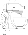
FIG. 1 is a side elevational view of a kitchen appliance illustrating a cord holder attached to the kitchen appliance and a power cord of the kitchen appliance wound about the cord holder; -
FIG. 2 is a top perspective view of a portion of the kitchen appliance illustrating a cord holder in an attached condition, wherein the cord holder is magnetically attached to a body of the kitchen appliance; -
FIG. 3 is a top perspective view of a portion of the kitchen appliance illustrating the cord holder in a detached condition, wherein the cord holder is detached from the body of the kitchen appliance; -
FIG. 4 is a top plan view of a cord holder illustrating a first flange, a barrel, and a second flange that defines a channel; -
FIG. 5 is a bottom plan view of a cord holder illustrating the first flange and a magnet in phantom; and -
FIG. 6 is a side elevational view of the cord holder illustrating the first flange, the second flange, and the barrel extending therebetween. - The components in the figures are not necessarily to scale, emphasis instead being placed upon illustrating the principles described herein.
- The present illustrated embodiments reside primarily in combinations of method steps and apparatus components related to a cord holder for a kitchen appliance. Accordingly, the apparatus components and method steps have been represented, where appropriate, by conventional symbols in the drawings, showing only those specific details that are pertinent to understanding the embodiments of the present disclosure so as not to obscure the disclosure with details that will be readily apparent to those of ordinary skill in the art having the benefit of the description herein. Further, like numerals in the description and drawings represent like elements.
- The terms "including," "comprises," "comprising," or any other variation thereof, are intended to cover a non-exclusive inclusion, such that a process, method, article, or apparatus that comprises a list of elements does not include only those elements but may include other elements not expressly listed or inherent to such process, method, article, or apparatus. An element preceded by "comprises a ... " does not, without more constraints, preclude the existence of additional identical elements in the process, method, article, or apparatus that comprises the element.
- The terms "substantial," "substantially," and variations thereof as used herein are intended to note that a described feature is equal or approximately equal to a value or description. For example, a "substantially planar" surface is intended to denote a surface that is planar or approximately planar. Moreover, "substantially" is intended to denote that two values are equal or approximately equal. In some embodiments, "substantially" may denote values within about 10% of each other, such as within about 5% of each other, or within about 2% of each other.
- Referring now to
FIGS. 1-6 , akitchen appliance 10 includes abody 12. Apower cord 14 extends outward from thebody 12. Acord holder 16 that is configured to receive thepower cord 14 via wrapping of thepower cord 14 about thecord holder 16 is operable between an attachedcondition 18, wherein thecord holder 16 is attached to thebody 12 via magnetic attraction, and adetached condition 20, wherein thecord holder 16 is detached from thebody 12. - Referring now to
FIG. 1 , anappliance 10 is illustrated. In various implementations, theappliance 10 may be thekitchen appliance 10. In some implementations, theappliance 10 may be acountertop kitchen appliance 10. In the embodiment illustrated inFIG. 1 , theappliance 10 is illustrated as astand mixer 22. Referring still toFIG. 1 , theappliance 10 includes abody 12. Thebody 12 can be formed of a plurality of components of theappliance 10, in various implementations. In some examples, thebody 12 comprises a ferromagnetic metal, such as iron. It is contemplated that thebody 12 may be formed of a variety of types of materials. In some implementations, thebody 12 may include amagnet 24. - Referring still to
FIG. 1 , theappliance 10 is anelectric appliance 10 that includes a cord for electrically coupling electrical components of the appliance 10 (e.g., motor, controls, etc.) with a power source (not shown). In the embodiment illustrated inFIG. 1 , thestand mixer 22 includes apower cord 14 that extends outward from thebody 12 of thestand mixer 22 proximate to abase 26 of thestand mixer 22. - Referring now to
FIGS. 1-3 , theappliance 10 includes thecord holder 16. Thecord holder 16 is configured to receive thepower cord 14 via wrapping of thepower cord 14 about thecord holder 16. In operation, a user may wrap an excess length ofpower cord 14 about thecord holder 16 to tidily store the excess length of thepower cord 14. Thecord holder 16 is operable between the attachedcondition 18 and thedetached condition 20. As illustrated inFIG. 1 , thecord holder 16 is attached to thebody 12 of thekitchen appliance 10 via magnetic attraction in the attachedcondition 18 of thecord holder 16. In thedetached condition 20 of thecord holder 16, thecord holder 16 is detached from thebody 12, as illustrated inFIG. 3 . - Referring now to
FIGS. 2-6 , thecord holder 16 includes abarrel 28 about which thepower cord 14 is configured to be wound. Thebarrel 28 includes afirst end 30 and asecond end 32 opposite thefirst end 30, as illustrated inFIG. 6 . In the embodiment illustrated inFIGS. 2-6 , thecord holder 16 includes thebarrel 28, afirst flange 34 extending outward from thefirst end 30 of thebarrel 28, and asecond flange 36 extending outward from thesecond end 32 of thebarrel 28 opposite thefirst end 30. In some implementations, thefirst flange 34 has a substantially stadium-shapedouter periphery 38 that is elongated in alongitudinal direction 40 of thefirst flange 34. For example, as illustrated inFIG. 5 , theouter periphery 38 of thefirst flange 34 is substantially stadium-shaped. In the illustrated embodiment, theouter periphery 38 of thefirst flange 34 has opposing sides that extend substantially parallel to thelongitudinal direction 40 of thefirst flange 34 and generally semicircular longitudinal ends opposite each other. In some implementations, thesecond flange 36 has a substantially stadium-shapedouter periphery 42 that is elongated in alongitudinal direction 44 of thesecond flange 36. For example, as illustrated inFIG. 4 , theouter periphery 42 of thesecond flange 36 is substantially stadium-shaped. - Referring still to
FIGS. 2-6 , in some implementations, thesecond flange 36 of thecord holder 16 defines achannel 46 for receiving a portion of thepower cord 14. Thesecond flange 36 may wholly define thechannel 46 or may define thechannel 46 in cooperation with other portions of thecord holder 16, such as thebarrel 28 of thecord holder 16. As illustrated inFIGS. 2 and3 , thechannel 46 is configured to receive a portion of thepower cord 14 therein. In various implementations, thefirst flange 34 is formed of a resiliently deformable material, and thechannel 46 is sized such that insertion of thepower cord 14 into thechannel 46 causes thepower cord 14 to contact and elastically deform the channel-defining portions of thesecond flange 36, such that thepower cord 14 is yieldingly retained within thechannel 46 by thesecond flange 36. - As illustrated in
FIGS. 2 ,3 , and4 , in some implementations, thechannel 46 interrupts theouter periphery 42 of thesecond flange 36 and extends across thesecond flange 36 in a direction that is substantially perpendicular to thelongitudinal direction 44 of thesecond flange 36. In the embodiment illustrated inFIG. 4 , thechannel 46 interrupts both sides of theouter periphery 42 of thesecond flange 36 that extend parallel to thelongitudinal direction 44 of thesecond flange 36. In the embodiment illustrated inFIG. 4 , thechannel 46 is defined at a longitudinal center point of thesecond flange 36. - Referring now to
FIGS. 2 ,3 , and6 , thecord holder 16 can include aretention tab 48. Theretention tab 48 extends outward from thefirst flange 34 toward thesecond flange 36 and is in a spaced-relationship with thebarrel 28 of thecord holder 16. As illustrated inFIGS. 2 and3 , theretention tab 48 is in a spaced-relationship with thebarrel 28 and is configured to selectively retain a portion of thepower cord 14 between theretention tab 48 and thebarrel 28 of thecord holder 16. - Referring now to
FIGS. 2-6 , thecord holder 16 may include amagnet 24 for magnetically attaching thecord holder 16 to thebody 12 of theappliance 10. In various implementations, thecord holder 16 may include a plurality and/or an array ofmagnets 24 for magnetically attaching thecord holder 16 to thebody 12 of theappliance 10. In an exemplary embodiment, thecord holder 16 includes an array ofmagnets 24 that attach and orient thecord holder 16 to thebody 12 of theappliance 10. It is contemplated that, in some implementations, thebody 12 of theappliance 10 may include amagnet 24 and thecord holder 16 may include a ferromagnetic material that is attracted to themagnet 24 of theappliance 10. In the embodiment illustrated inFIGS. 5 and 6 , thecord holder 16 includes themagnet 24. Themagnet 24 is configured to attach thecord holder 16 to thebody 12 in the attachedcondition 18 of thecord holder 16. In various implementations, themagnet 24 is oriented such that a side of thefirst flange 34 that is opposite thebarrel 28 of thecord holder 16 is configured to abut thebody 12 of theappliance 10 in the attachedcondition 18 of thecord holder 16. Themagnet 24 may be coupled to various portions of thecord holder 16. For example, themagnet 24 may be coupled to and/or disposed within thebarrel 28 of thecord holder 16, in some implementations. In various implementations, themagnet 24 is coupled to thefirst flange 34 of thecord holder 16. For example, themagnet 24 may be a portion of thefirst flange 34 of thecord holder 16 that is disposed within and/or externally of the adjacent portions of thefirst flange 34. In the embodiment illustrated inFIGS. 5 and 6 , themagnet 24 is disposed within thefirst flange 34 of thecord holder 16. - In operation of an exemplary embodiment of a
kitchen appliance 10, such as thestand mixer 22 illustrated inFIG. 1 , a user places thestand mixer 22 on a countertop proximate to an electrical outlet into which a plug coupled to thepower cord 14 of thestand mixer 22 may be inserted to supply power to thestand mixer 22. The user identifies that the length of thepower cord 14 is greater than the distance between thestand mixer 22 and the electrical outlet, such that an extent of thepower cord 14 will be slacked and rest untidily on the countertop. Next, the user removes the cord holder 16 (currently empty) from the attachedcondition 18, wherein thecord holder 16 was magnetically attached to a rear side of thestand mixer 22, and winds the slacked extent ofpower cord 14 about thebarrel 28 of thecord holder 16 between the first andsecond flanges power cord 14 is wound about thebarrel 28, the user inserts a tag end of the slacked extent of thepower cord 14 into thechannel 46 defined by thesecond flange 36, such that the wound state of thepower cord 14 about thecord holder 16 is yieldingly maintained. Next, the user moves thecord holder 16 from thedetached condition 20 to the attachedcondition 18, wherein thefirst flange 34 abuts thebody 12 of thestand mixer 22 and is maintained in that position via magnetic attraction between thebody 12 and themagnet 24 of thecord holder 16. - The
appliance 10 of the present disclosure may provide a variety of advantages. First, thecord holder 16 being operable between the attached anddetached conditions appliance 10 may conveniently allow a user to freely hold thecord holder 16 separately from thebody 12 of theappliance 10 while winding thepower cord 14 about thebarrel 28. Second, thechannel 46 extending across the entirety of thesecond flange 36, and interrupting theouter periphery 42 of thesecond flange 36 may allow for a length of thepower cord 14 to be received within thechannel 46 in an orientation that is substantially parallel to the length of the channel 46 (i.e., perpendicular to thelongitudinal direction 44 of the second flange 36). A lengthwise extent of thepower cord 14 being received by thechannel 46 in this way results in a larger amount of surface area of thepower cord 14 being contacted and retained by the channel-defining portions of thesecond flange 36. This results in better overall retention of thepower cord 14 within thechannel 46 compared to an apparatus in which a power cord is received within a channel while extending perpendicularly relative to the lengthwise direction of the channel. Thepower cord 14 being received within thechannel 46 parallel to the length of thechannel 46 is particularly advantageous in the present application, as power cords forappliances 10, such as thestand mixer 22, are often more rigid and unruly than flexible cords, such as those used for headphones. Third, thecord holder 16 being operable to magnetically attach to thebody 12 of theappliance 10 may allow for a user to conveniently conceal thecord holder 16 and thepower cord 14 wrapped about thecord holder 16 from view by attaching thecord holder 16 to various portions of thebody 12 depending on the orientation of theappliance 10 relative to the user's viewpoint. - According to one aspect of the present disclosure, a kitchen appliance includes a body, a power cord extending outward from the body, and a cord holder configured to receive the power cord via wrapping of the power cord about the cord holder. The cord holder is operable between an attached condition and a detached condition. In the attached condition, the cord holder is attached to the body via magnetic attraction. In the detached condition, the cord holder is detached from the body.
- According to another aspect, the body comprises a ferromagnetic metal, and the cord holder comprises a magnet that is magnetically attracted to the ferromagnetic metal.
- According to another aspect, the kitchen appliance is a countertop kitchen appliance.
- According to another aspect, the kitchen appliance is a stand mixer.
- According to another aspect, the cord holder includes a barrel about which the power cord is configured to be wound. The barrel has a first end and a second end opposite the first end. The cord holder also includes a first flange extending outward from the first end of the barrel. The cord holder further includes a second flange extending outward from the second end of the barrel opposite the first end. The cord holder additionally includes a magnet that magnetically attaches the cord holder to the body in the attached condition of the cord holder. The magnet is oriented such that a side of the first flange opposite the barrel is configured to abut the body in the attached condition of the cord holder.
- According to another aspect, the magnet is coupled to the first flange.
- According to another aspect, the second flange defines a channel for receiving a portion of the power cord.
- According to another aspect, the second flange has a substantially stadium-shaped outer periphery that is elongated in a longitudinal direction of the second flange.
- According to another aspect, the channel interrupts the outer periphery of the second flange and extends across the second flange in a direction substantially perpendicular to the longitudinal direction of the second flange.
- According to another aspect, the cord holder further includes a retention tab that extends outward from the first flange toward the second flange. The retention tab is in a spaced-relationship with the barrel and is configured to selectively retain a portion of the power cord between the retention tab and the barrel.
- According to another aspect of the present disclosure, a cord holder for selective attachment to an appliance includes a barrel about which a power cord of the appliance is configured to be wound. The barrel has a first end and a second end opposite the first end. The cord holder also includes a first flange extending outward from the first end of the barrel. The cord holder further includes a second flange extending outward from the second end of the barrel and having a substantially stadium-shaped outer periphery that is elongated in a longitudinal direction of the second flange. The second flange defines a channel that interrupts the substantially stadium-shaped outer periphery of the second flange and extends across the second flange in a direction substantially perpendicular to the longitudinal direction. The cord holder additionally includes a magnet that is configured to magnetically attach the cord holder to a body of the appliance in an attached condition of the cord holder. The magnet is oriented such that a side of the first flange opposite the barrel is configured to abut the body in the attached condition of the cord holder.
- According to another aspect, the first flange includes a substantially stadium-shaped outer periphery that is elongated in a longitudinal direction of the first flange.
- According to another aspect, the longitudinal direction of the first flange is substantially parallel to the longitudinal direction of the second flange.
- According to another aspect, the cord holder further includes a retention tab that extends outward from the first flange toward the second flange. The retention tab is in a spaced-relationship with the barrel and is configured to selectively retain a portion of the power cord between the retention tab and the barrel.
- According to another aspect, the magnet is a portion of the first flange.
- According to yet another aspect of the present disclosure, a kitchen appliance includes a body, a power cord extending outward from the body, and a cord holder configured to receive the power cord via wrapping of the power cord about the cord holder. The cord holder is operable between an attached condition and a detached condition. In the attached condition, the cord holder is attached to the body via magnetic attraction. In the detached condition, the cord holder is detached from the body. The cord holder includes a barrel about which the power cord is configured to be wound. The barrel has a first end and a second end opposite the first end. The cord holder also includes a first flange extending outward from the first end of the barrel. The cord holder further includes a second flange extending outward from the second end of the barrel and having a substantially stadium-shaped outer periphery that is elongated in a longitudinal direction of the second flange. The second flange defines a channel that interrupts the substantially stadium-shaped outer periphery of the second flange and extends across the second flange in a direction substantially perpendicular to the longitudinal direction. The cord holder additionally includes a magnet that is configured to magnetically attach the cord holder to the body of the kitchen appliance in the attached condition of the cord holder. The magnet is oriented such that a side of the first flange opposite the barrel is configured to abut the body in the attached condition of the cord holder.
- According to another aspect, the kitchen appliance is a countertop kitchen appliance.
- According to another aspect, the kitchen appliance is a stand mixer.
- According to another aspect, the cord holder further includes a retention tab that extends outward from the first flange toward the second flange. The retention tab is in a spaced-relationship with the barrel and is configured to selectively retain a portion of the power cord between the retention tab and the barrel.
- According to another aspect, the magnet is a portion of the first flange.
- It will be understood by one having ordinary skill in the art that construction of the described disclosure and other components is not limited to any specific material. Other exemplary embodiments of the disclosure disclosed herein may be formed from a wide variety of materials, unless described otherwise herein.
- For purposes of this disclosure, the term "coupled" (in all of its forms, couple, coupling, coupled, etc.) generally means the joining of two components (electrical or mechanical) directly or indirectly to one another. Such joining may be stationary in nature or movable in nature. Such joining may be achieved with the two components (electrical or mechanical) and any additional intermediate members being integrally formed as a single unitary body with one another or with the two components. Such joining may be permanent in nature or may be removable or releasable in nature unless otherwise stated.
- It is also important to note that the construction and arrangement of the elements of the disclosure as shown in the exemplary embodiments is illustrative only. Although only a few embodiments of the present innovations have been described in detail in this disclosure, those skilled in the art who review this disclosure will readily appreciate that many modifications are possible (e.g., variations in sizes, dimensions, structures, shapes and proportions of the various elements, values of parameters, mounting arrangements, use of materials, colors, orientations, etc.) without materially departing from the novel teachings and advantages of the subject matter recited. For example, elements shown as integrally formed may be constructed of multiple parts or elements shown as multiple parts may be integrally formed, the operation of the interfaces may be reversed or otherwise varied, the length or width of the structures and/or members or connector or other elements of the system may be varied, the nature or number of adjustment positions provided between the elements may be varied. It should be noted that the elements and/or assemblies of the system may be constructed from any of a wide variety of materials that provide sufficient strength or durability, in any of a wide variety of colors, textures, and combinations. Accordingly, all such modifications are intended to be included within the scope of the present innovations. Other substitutions, modifications, changes, and omissions may be made in the design, operating conditions, and arrangement of the desired and other exemplary embodiments without departing from the spirit of the present innovations.
- It will be understood that any described processes or steps within described processes may be combined with other disclosed processes or steps to form structures within the scope of the present disclosure. The exemplary structures and processes disclosed herein are for illustrative purposes and are not to be construed as limiting.
Claims (15)
- A kitchen appliance (10), comprising:a body (12);a power cord (14) extending outward from the body (12); anda cord holder (16) configured to receive the power cord (14) via wrapping of the power cord (14) about the cord holder (16), wherein the cord holder (16) is operable between an attached condition (18), wherein the cord holder (16) is attached to the body (12) via magnetic attraction, and a detached condition (20), wherein the cord holder (16) is detached from the body (12).
- The kitchen appliance (10) of claim 1, wherein the body (12) comprises a ferromagnetic metal, and the cord holder (16) comprises a magnet (24) that is magnetically attracted to the ferromagnetic metal.
- The kitchen appliance (10) according to claims 1 or 2, wherein the kitchen appliance (10) is a countertop kitchen appliance.
- The kitchen appliance (10) as in any one of claims 1-3, wherein the kitchen appliance (10) is a stand mixer (22).
- The kitchen appliance (10) of claim 1, wherein the cord holder (16) comprises:a barrel (28) about which the power cord (14) is configured to be wound, the barrel (28) having a first end (30) and a second end (32) opposite the first end (30);a first flange (34) extending outward from the first end (30) of the barrel (28);a second flange (36) extending outward from the second end (32) of the barrel (28) opposite the first end (30); anda magnet (24) that magnetically attaches the cord holder (16) to the body (12) in the attached condition (18) of the cord holder (16), wherein the magnet (24) is oriented such that a side of the first flange (34) opposite the barrel (28) is configured to abut the body (12) in the attached condition (18) of the cord holder (16).
- The kitchen appliance (10) of claim 5, wherein the second flange (36) defines a channel (46) for receiving a portion of the power cord (14).
- The kitchen appliance (10) of claim 6, wherein the second flange (36) has a substantially stadium-shaped outer periphery (42) that is elongated in a longitudinal direction (44) of the second flange (36).
- The kitchen appliance (10) of claim 7, wherein the channel (46) interrupts the outer periphery (42) of the second flange (36) and extends across the second flange (36) in a direction substantially perpendicular to the longitudinal direction (44) of the second flange (36).
- The kitchen appliance (10) of claim 8, wherein the substantially stadium-shaped outer periphery (42) of the second flange (36) includes opposing sides that extend substantially parallel to the longitudinal direction (44) of the second flange (36), and the channel (46) interrupts both of the opposing sides of the outer periphery (42).
- The kitchen appliance (10) as in any one of claims 5-9, wherein channel-defining portions of the second flange (36) are configured to elastically deform due to insertion of the power cord (14) into the channel (46).
- The kitchen appliance (10) as in any one of claims 5-10, wherein the cord holder (16) further comprises:
a retention tab (48) that extends outward from the first flange (34) toward the second flange (36), wherein the retention tab (48) is in a spaced-relationship with the barrel (28) and is configured to selectively retain a portion of the power cord (14) between the retention tab (48) and the barrel (28). - The kitchen appliance (10) as in any one of claims 6-11, wherein the first flange (34) includes a substantially stadium-shaped outer periphery (38) that is elongated in a longitudinal direction (40) of the first flange (34).
- The kitchen appliance (10) of claim 12, wherein the longitudinal direction (40) of the first flange (36) is substantially parallel to the longitudinal direction (44) of the second flange (36).
- The kitchen appliance (10) as in any one of claims 5-13, wherein the magnet (24) is coupled to the first flange (34).
- The kitchen appliance (10) as in any one of claims 5-13, wherein the magnet (24) is a portion of the first flange (34).
Applications Claiming Priority (1)
| Application Number | Priority Date | Filing Date | Title |
|---|---|---|---|
| US18/357,608 US20250031906A1 (en) | 2023-07-24 | 2023-07-24 | Cord holder for a kitchen appliance |
Publications (2)
| Publication Number | Publication Date |
|---|---|
| EP4497353A1 true EP4497353A1 (en) | 2025-01-29 |
| EP4497353B1 EP4497353B1 (en) | 2026-03-11 |
Family
ID=91969199
Family Applications (1)
| Application Number | Title | Priority Date | Filing Date |
|---|---|---|---|
| EP24190604.9A Active EP4497353B1 (en) | 2023-07-24 | 2024-07-24 | Cord holder for a kitchen appliance |
Country Status (3)
| Country | Link |
|---|---|
| US (1) | US20250031906A1 (en) |
| EP (1) | EP4497353B1 (en) |
| AU (1) | AU2024205060A1 (en) |
Families Citing this family (2)
| Publication number | Priority date | Publication date | Assignee | Title |
|---|---|---|---|---|
| US20250224050A1 (en) * | 2024-01-04 | 2025-07-10 | Matthew Robinson | Retainer for holding cords, cables and other items |
| US20260081410A1 (en) * | 2024-09-18 | 2026-03-19 | Joel Dennis | One-way retractable cable unit with magnetic center |
Citations (3)
| Publication number | Priority date | Publication date | Assignee | Title |
|---|---|---|---|---|
| US9366360B2 (en) * | 2013-05-14 | 2016-06-14 | A. Shane Alcorn | Cord bracket and method of use |
| WO2022112800A1 (en) * | 2020-11-30 | 2022-06-02 | Kenwood Limited | Electrical appliance |
| US11658445B1 (en) * | 2017-03-21 | 2023-05-23 | Brian M. Aumiller | Cord management device |
Family Cites Families (34)
| Publication number | Priority date | Publication date | Assignee | Title |
|---|---|---|---|---|
| US1696495A (en) * | 1927-07-11 | 1928-12-25 | Malte J Malling | Electric appliance |
| US2231001A (en) * | 1938-08-26 | 1941-02-11 | Henry O Engstrom | Carrier for slack in electrical cord conductors |
| US2565339A (en) * | 1946-07-03 | 1951-08-21 | Chester R Anderson | Cord reel |
| US2789798A (en) * | 1952-12-30 | 1957-04-23 | Hoover Co | Folding food mixers |
| GB836306A (en) * | 1957-04-12 | 1960-06-01 | Siemens Ag | Improvements in or relating to coil-spools |
| US4150798A (en) * | 1977-08-10 | 1979-04-24 | Aragon Manuel Y | Cord and line storage reel |
| US4645905A (en) * | 1985-02-27 | 1987-02-24 | Dart Industries, Inc. | Foldable household appliance |
| EP0243539A1 (en) * | 1986-04-29 | 1987-11-04 | Koninklijke Philips Electronics N.V. | Coffee maker |
| DE3815177C1 (en) * | 1988-05-04 | 1989-09-28 | Braun Ag, 6000 Frankfurt, De | |
| DE3820007C1 (en) * | 1988-06-11 | 1989-08-24 | Braun Ag, 6000 Frankfurt, De | Mounting for one or more working tools of a domestic appliance |
| US4901938A (en) * | 1988-11-21 | 1990-02-20 | Cantley Donald G | Electrical cord retractor |
| DE4123267A1 (en) * | 1991-07-13 | 1993-01-21 | Braun Ag | Cable holder for small electrical appliance e.g. bread toaster - uses protruding elements on either side of cable exit opening around which cable is wound |
| US6164582A (en) * | 1994-10-18 | 2000-12-26 | Reel Butler, Inc. | Enhanced storage system for electrical appliances, powercords and adapters |
| US5531333A (en) * | 1994-10-18 | 1996-07-02 | Vara; James E. | Storage system for electrical appliances, powercords and adapters |
| WO1998044820A1 (en) * | 1997-04-09 | 1998-10-15 | Boris Jakovlevich Rezvoushkine | Holding unit |
| DE19822635C2 (en) * | 1998-05-20 | 2000-04-20 | Helmar Kess | Cable attachment |
| TW372674U (en) * | 1998-07-21 | 1999-10-21 | Cotron Corp | Earphone storage case |
| GB2345650B (en) * | 1999-01-12 | 2002-11-13 | Kenwood Marks Ltd | Tool storage arrangements for domestic appliances |
| US6483033B1 (en) * | 2000-10-11 | 2002-11-19 | Motorola, Inc. | Cable management apparatus and method |
| CA2363446C (en) * | 2000-11-20 | 2009-12-01 | Francis Archambault | Electrical outlet cord support |
| US6957978B2 (en) * | 2003-07-31 | 2005-10-25 | Drew Zoller | Cord retainer |
| US7108544B2 (en) * | 2003-07-31 | 2006-09-19 | Drew Zoller | Cord retainer |
| US7077693B1 (en) * | 2005-01-19 | 2006-07-18 | Blue Lounge Design, Llc | Cable management device |
| IS8682A (en) * | 2007-10-12 | 2009-04-13 | Royal Ehf | cable Sets |
| US20120077372A1 (en) * | 2010-09-24 | 2012-03-29 | John Mezzalingua Associates, Inc. | Cable jumper hand reel |
| CN106081746B (en) * | 2015-04-27 | 2019-07-09 | 弗莱克斯电子有限责任公司 | Removable reel for optical fiber storage |
| USD774383S1 (en) * | 2015-06-18 | 2016-12-20 | Avi Corporation | Cable spool |
| US20170081146A1 (en) * | 2015-09-21 | 2017-03-23 | John Ernest Dockray | Extension Cord Safety System |
| US10390589B2 (en) * | 2016-03-15 | 2019-08-27 | Nike, Inc. | Drive mechanism for automated footwear platform |
| US10799072B2 (en) * | 2018-04-13 | 2020-10-13 | Hamilton Beach Brands, Inc. | Stand mixer with bowl lift |
| US11820626B2 (en) * | 2019-05-07 | 2023-11-21 | Ryan Kohli | Systems and methods for electrical cord storage |
| US11545819B2 (en) * | 2021-06-01 | 2023-01-03 | Eagle Fan | Wire management bracket for wireless charger |
| US12017884B2 (en) * | 2021-10-18 | 2024-06-25 | Kevin Christian Casey | Cable organizing device |
| US20240292978A1 (en) * | 2023-03-03 | 2024-09-05 | StoreBound LLC | Handheld appliance |
-
2023
- 2023-07-24 US US18/357,608 patent/US20250031906A1/en active Pending
-
2024
- 2024-07-24 AU AU2024205060A patent/AU2024205060A1/en active Pending
- 2024-07-24 EP EP24190604.9A patent/EP4497353B1/en active Active
Patent Citations (3)
| Publication number | Priority date | Publication date | Assignee | Title |
|---|---|---|---|---|
| US9366360B2 (en) * | 2013-05-14 | 2016-06-14 | A. Shane Alcorn | Cord bracket and method of use |
| US11658445B1 (en) * | 2017-03-21 | 2023-05-23 | Brian M. Aumiller | Cord management device |
| WO2022112800A1 (en) * | 2020-11-30 | 2022-06-02 | Kenwood Limited | Electrical appliance |
Also Published As
| Publication number | Publication date |
|---|---|
| AU2024205060A1 (en) | 2025-02-13 |
| US20250031906A1 (en) | 2025-01-30 |
| EP4497353B1 (en) | 2026-03-11 |
Similar Documents
| Publication | Publication Date | Title |
|---|---|---|
| EP4497353B1 (en) | Cord holder for a kitchen appliance | |
| US4991265A (en) | Cord tie device | |
| US8121304B2 (en) | Anti-tangle device and method for preventing cord tangling | |
| US20140065875A1 (en) | Power supply cord storage mechanism | |
| EP2264872A1 (en) | Dc motor | |
| US5518417A (en) | Multiple electrical socket | |
| CN107980165A (en) | The fixed structure of magnet core | |
| AU2016211994A1 (en) | Elongate attachable flexible magnetic article holder | |
| US6833507B2 (en) | Magnetic cord retainer | |
| US20110031006A1 (en) | Cable assembly with cable holder having anti-emi function | |
| US20140010400A1 (en) | Magnetic coupling mechanism for earphone wires | |
| JPH104654A (en) | Commutator brush-holding clip and electric connector of coupled type | |
| EP1244127A3 (en) | Electrical switching element | |
| CN211981061U (en) | Magnetic data line | |
| US10075010B2 (en) | Tablet connection system | |
| US4396243A (en) | Electrical connector for electromagnetic device | |
| US8872407B2 (en) | Electric motor arrangement with improved brush and spring elements | |
| CN204022150U (en) | The line clamping device of mobile device | |
| CN219304124U (en) | Cable tie data cable and data cable assembly | |
| GB2130552A (en) | Cord or wire storage device | |
| CN218039786U (en) | Extension antenna | |
| KR101944042B1 (en) | Fastening band to prevent separation of charging cable | |
| CN222840767U (en) | Earphone show shelf and earphone show stand | |
| US20050280481A1 (en) | Wave filter assembly | |
| CN210404949U (en) | Wire harness fixing part for brushless motor |
Legal Events
| Date | Code | Title | Description |
|---|---|---|---|
| PUAI | Public reference made under article 153(3) epc to a published international application that has entered the european phase |
Free format text: ORIGINAL CODE: 0009012 |
|
| STAA | Information on the status of an ep patent application or granted ep patent |
Free format text: STATUS: THE APPLICATION HAS BEEN PUBLISHED |
|
| AK | Designated contracting states |
Kind code of ref document: A1 Designated state(s): AL AT BE BG CH CY CZ DE DK EE ES FI FR GB GR HR HU IE IS IT LI LT LU LV MC ME MK MT NL NO PL PT RO RS SE SI SK SM TR |
|
| STAA | Information on the status of an ep patent application or granted ep patent |
Free format text: STATUS: REQUEST FOR EXAMINATION WAS MADE |
|
| 17P | Request for examination filed |
Effective date: 20250729 |
|
| GRAP | Despatch of communication of intention to grant a patent |
Free format text: ORIGINAL CODE: EPIDOSNIGR1 |
|
| STAA | Information on the status of an ep patent application or granted ep patent |
Free format text: STATUS: GRANT OF PATENT IS INTENDED |
|
| INTG | Intention to grant announced |
Effective date: 20251006 |
|
| GRAS | Grant fee paid |
Free format text: ORIGINAL CODE: EPIDOSNIGR3 |
|
| GRAA | (expected) grant |
Free format text: ORIGINAL CODE: 0009210 |
|
| STAA | Information on the status of an ep patent application or granted ep patent |
Free format text: STATUS: THE PATENT HAS BEEN GRANTED |
|
| AK | Designated contracting states |
Kind code of ref document: B1 Designated state(s): AL AT BE BG CH CY CZ DE DK EE ES FI FR GB GR HR HU IE IS IT LI LT LU LV MC ME MK MT NL NO PL PT RO RS SE SI SK SM TR |
|
| REG | Reference to a national code |
Ref country code: CH Ref legal event code: F10 Free format text: ST27 STATUS EVENT CODE: U-0-0-F10-F00 (AS PROVIDED BY THE NATIONAL OFFICE) Effective date: 20260311 Ref country code: GB Ref legal event code: FG4D |
|
| REG | Reference to a national code |
Ref country code: DE Ref legal event code: R096 Ref document number: 602024003109 Country of ref document: DE |
|
| P01 | Opt-out of the competence of the unified patent court (upc) registered |
Free format text: CASE NUMBER: UPC_APP_0008388_4497353/2026 Effective date: 20260302 |
|
| REG | Reference to a national code |
Ref country code: IE Ref legal event code: FG4D |