EP4497313A1 - Push working machine - Google Patents
Push working machine Download PDFInfo
- Publication number
- EP4497313A1 EP4497313A1 EP24180652.0A EP24180652A EP4497313A1 EP 4497313 A1 EP4497313 A1 EP 4497313A1 EP 24180652 A EP24180652 A EP 24180652A EP 4497313 A1 EP4497313 A1 EP 4497313A1
- Authority
- EP
- European Patent Office
- Prior art keywords
- acceleration
- working machine
- controller
- motor
- push
- Prior art date
- Legal status (The legal status is an assumption and is not a legal conclusion. Google has not performed a legal analysis and makes no representation as to the accuracy of the status listed.)
- Granted
Links
Images


Classifications
-
- H—ELECTRICITY
- H04—ELECTRIC COMMUNICATION TECHNIQUE
- H04W—WIRELESS COMMUNICATION NETWORKS
- H04W4/00—Services specially adapted for wireless communication networks; Facilities therefor
- H04W4/02—Services making use of location information
- H04W4/025—Services making use of location information using location based information parameters
-
- A—HUMAN NECESSITIES
- A01—AGRICULTURE; FORESTRY; ANIMAL HUSBANDRY; HUNTING; TRAPPING; FISHING
- A01D—HARVESTING; MOWING
- A01D34/00—Mowers; Mowing apparatus of harvesters
- A01D34/006—Control or measuring arrangements
-
- A—HUMAN NECESSITIES
- A01—AGRICULTURE; FORESTRY; ANIMAL HUSBANDRY; HUNTING; TRAPPING; FISHING
- A01D—HARVESTING; MOWING
- A01D34/00—Mowers; Mowing apparatus of harvesters
- A01D34/006—Control or measuring arrangements
- A01D34/008—Control or measuring arrangements for automated or remotely controlled operation
-
- A—HUMAN NECESSITIES
- A01—AGRICULTURE; FORESTRY; ANIMAL HUSBANDRY; HUNTING; TRAPPING; FISHING
- A01D—HARVESTING; MOWING
- A01D34/00—Mowers; Mowing apparatus of harvesters
- A01D34/01—Mowers; Mowing apparatus of harvesters characterised by features relating to the type of cutting apparatus
- A01D34/412—Mowers; Mowing apparatus of harvesters characterised by features relating to the type of cutting apparatus having rotating cutters
- A01D34/63—Mowers; Mowing apparatus of harvesters characterised by features relating to the type of cutting apparatus having rotating cutters having cutters rotating about a vertical axis
- A01D34/64—Mowers; Mowing apparatus of harvesters characterised by features relating to the type of cutting apparatus having rotating cutters having cutters rotating about a vertical axis mounted on a vehicle, e.g. a tractor, or drawn by an animal or a vehicle
-
- A—HUMAN NECESSITIES
- A01—AGRICULTURE; FORESTRY; ANIMAL HUSBANDRY; HUNTING; TRAPPING; FISHING
- A01D—HARVESTING; MOWING
- A01D34/00—Mowers; Mowing apparatus of harvesters
- A01D34/01—Mowers; Mowing apparatus of harvesters characterised by features relating to the type of cutting apparatus
- A01D34/412—Mowers; Mowing apparatus of harvesters characterised by features relating to the type of cutting apparatus having rotating cutters
- A01D34/63—Mowers; Mowing apparatus of harvesters characterised by features relating to the type of cutting apparatus having rotating cutters having cutters rotating about a vertical axis
- A01D34/67—Mowers; Mowing apparatus of harvesters characterised by features relating to the type of cutting apparatus having rotating cutters having cutters rotating about a vertical axis hand-guided by a walking operator
- A01D34/68—Mowers; Mowing apparatus of harvesters characterised by features relating to the type of cutting apparatus having rotating cutters having cutters rotating about a vertical axis hand-guided by a walking operator with motor driven cutters or wheels
- A01D34/6806—Driving mechanisms
-
- A—HUMAN NECESSITIES
- A01—AGRICULTURE; FORESTRY; ANIMAL HUSBANDRY; HUNTING; TRAPPING; FISHING
- A01D—HARVESTING; MOWING
- A01D34/00—Mowers; Mowing apparatus of harvesters
- A01D34/01—Mowers; Mowing apparatus of harvesters characterised by features relating to the type of cutting apparatus
- A01D34/412—Mowers; Mowing apparatus of harvesters characterised by features relating to the type of cutting apparatus having rotating cutters
- A01D34/63—Mowers; Mowing apparatus of harvesters characterised by features relating to the type of cutting apparatus having rotating cutters having cutters rotating about a vertical axis
- A01D34/67—Mowers; Mowing apparatus of harvesters characterised by features relating to the type of cutting apparatus having rotating cutters having cutters rotating about a vertical axis hand-guided by a walking operator
- A01D34/68—Mowers; Mowing apparatus of harvesters characterised by features relating to the type of cutting apparatus having rotating cutters having cutters rotating about a vertical axis hand-guided by a walking operator with motor driven cutters or wheels
- A01D34/69—Mowers; Mowing apparatus of harvesters characterised by features relating to the type of cutting apparatus having rotating cutters having cutters rotating about a vertical axis hand-guided by a walking operator with motor driven cutters or wheels with motor driven wheels
-
- A—HUMAN NECESSITIES
- A01—AGRICULTURE; FORESTRY; ANIMAL HUSBANDRY; HUNTING; TRAPPING; FISHING
- A01D—HARVESTING; MOWING
- A01D34/00—Mowers; Mowing apparatus of harvesters
- A01D34/01—Mowers; Mowing apparatus of harvesters characterised by features relating to the type of cutting apparatus
- A01D34/412—Mowers; Mowing apparatus of harvesters characterised by features relating to the type of cutting apparatus having rotating cutters
- A01D34/63—Mowers; Mowing apparatus of harvesters characterised by features relating to the type of cutting apparatus having rotating cutters having cutters rotating about a vertical axis
- A01D34/82—Other details
-
- G—PHYSICS
- G08—SIGNALLING
- G08C—TRANSMISSION SYSTEMS FOR MEASURED VALUES, CONTROL OR SIMILAR SIGNALS
- G08C17/00—Arrangements for transmitting signals characterised by the use of a wireless electrical link
- G08C17/02—Arrangements for transmitting signals characterised by the use of a wireless electrical link using a radio link
-
- H—ELECTRICITY
- H04—ELECTRIC COMMUNICATION TECHNIQUE
- H04W—WIRELESS COMMUNICATION NETWORKS
- H04W4/00—Services specially adapted for wireless communication networks; Facilities therefor
- H04W4/70—Services for machine-to-machine communication [M2M] or machine type communication [MTC]
-
- A—HUMAN NECESSITIES
- A01—AGRICULTURE; FORESTRY; ANIMAL HUSBANDRY; HUNTING; TRAPPING; FISHING
- A01D—HARVESTING; MOWING
- A01D2101/00—Lawn-mowers
-
- A—HUMAN NECESSITIES
- A01—AGRICULTURE; FORESTRY; ANIMAL HUSBANDRY; HUNTING; TRAPPING; FISHING
- A01D—HARVESTING; MOWING
- A01D34/00—Mowers; Mowing apparatus of harvesters
- A01D34/01—Mowers; Mowing apparatus of harvesters characterised by features relating to the type of cutting apparatus
- A01D34/412—Mowers; Mowing apparatus of harvesters characterised by features relating to the type of cutting apparatus having rotating cutters
- A01D34/63—Mowers; Mowing apparatus of harvesters characterised by features relating to the type of cutting apparatus having rotating cutters having cutters rotating about a vertical axis
- A01D34/76—Driving mechanisms for the cutters
- A01D34/78—Driving mechanisms for the cutters electric
-
- A—HUMAN NECESSITIES
- A01—AGRICULTURE; FORESTRY; ANIMAL HUSBANDRY; HUNTING; TRAPPING; FISHING
- A01D—HARVESTING; MOWING
- A01D69/00—Driving mechanisms or parts thereof for harvesters or mowers
- A01D69/02—Driving mechanisms or parts thereof for harvesters or mowers electric
Definitions
- the present disclosure relates to garden tools, for example, a push working machine and mower.
- an operating member is generally disposed on the handle and used for a user to control the operation states of a traveling motor and a working motor of the machine.
- the user can start the mower through the operating member such that the mower travels and/or mows.
- the user can control the process of starting the mower and can control at least the starting speed or the change in speed.
- an object of the present application is to provide a mower with variable starting acceleration.
- a push working machine includes a body including at least a traveling assembly, a traveling motor driving the traveling assembly, a functional assembly, and a functional motor driving the functional assembly; a handle device connected to the body and including at least an operating member for a user to operate; a controller configured to control at least the working states of the traveling motor and the functional motor; and a power interface for connecting electrical energy capable of supplying power to at least the traveling motor and the functional motor.
- the controller is configured to, in response to a start signal, be capable of controlling the traveling motor to accelerate to the first speed with the first acceleration and accelerate to the target self-propelled speed with the second acceleration.
- the second acceleration is less than the first acceleration.
- the push working machine further includes an Internet of Things (IoT) module configured to be connected to at least the controller and capable of transmitting communication data to the controller.
- IoT Internet of Things
- an IoT module is configured to communicate with an external terminal and acquire startup setting data sent by the external terminal.
- the controller is configured to acquire the startup setting data and adjust at least the first acceleration and/or the second acceleration according to the startup setting data.
- the IoT module supports at least one of wired communication technology and wireless communication technology.
- the IoT module supports at least one of transmission access, network switching, mobile communications, wireless communications, optical communications, satellite communications, support management, and private network communications.
- the IoT module supports at least one of cellular network technology, wireless local area network (LAN) technology, wireless personal area network (PAN) technology, satellite communication technology, infrared communication technology, optical fiber communication technology, Bluetooth Low Energy (Bluetooth LE) technology, long range (LoRa) technology, Wi-Fi, and Zigbee.
- LAN wireless local area network
- PAN wireless personal area network
- satellite communication technology satellite communication technology
- infrared communication technology optical fiber communication technology
- Bluetooth Low Energy (Bluetooth LE) technology Bluetooth Low Energy (Bluetooth LE) technology
- LiRa) technology long range technology
- Wi-Fi Wi-Fi
- Zigbee Zigbee
- the controller is configured to acquire the startup setting data and adjust the first acceleration and/or the second acceleration according to the startup setting data.
- the controller includes a data storage unit configured to store historical startup setting data.
- the controller further includes a control unit configured to set the first acceleration and/or the second acceleration according to the historical startup setting data.
- a push self-propelled mower includes a body including at least a traveling assembly, a traveling motor driving the traveling assembly, a cutting assembly, and a cutting motor driving the cutting assembly; a handle device connected to the body and including at least an operating member for a user to operate; a controller configured to control at least the working states of the traveling motor and the cutting motor; and a power interface for connecting electrical energy capable of supplying power to at least the traveling motor and the cutting motor.
- the controller is configured to, in response to a start signal, be capable of controlling the traveling motor to accelerate to the target self-propelled speed with at least two different accelerations.
- the push mower further includes an IoT module configured to be connected to at least the controller and capable of transmitting communication data to the controller.
- an IoT module is configured to communicate with an external terminal and acquire startup setting data sent by the external terminal.
- the controller is configured to acquire the startup setting data and adjust the acceleration according to the startup setting data.
- a push mower includes a body including at least a traveling assembly, a traveling motor driving the traveling assembly, a cutting assembly, and a cutting motor driving the cutting assembly; a handle device connected to the body and including at least an operating member for a user to operate; a controller configured to control at least the working states of the traveling motor and the cutting motor; and a power interface for connecting electrical energy capable of supplying power to at least the traveling motor and the cutting motor.
- the controller is configured to, in response to a self-propelled start signal, be capable of controlling the traveling motor to accelerate to the target self-propelled speed with the variable self-propelled acceleration; or in response to a mowing start signal, be capable of controlling the cutting motor to accelerate to the target mowing speed with the variable mowing acceleration.
- the self-propelled acceleration includes at least the first acceleration and the second acceleration, where the first acceleration is greater than the second acceleration; and the mowing acceleration includes at least the third acceleration and the fourth acceleration, where the third acceleration is greater than the fourth acceleration.
- the push mower further includes an IoT module configured to be connected to at least the controller and capable of transmitting communication data to the controller.
- the IoT module is configured to communicate with an external terminal and acquire startup setting data sent by the external terminal.
- the controller is configured to acquire the startup setting data and adjust the self-propelled acceleration and/or the mowing acceleration according to the startup setting data.
- the controller includes a data storage unit configured to store historical startup setting data.
- the controller further includes a control unit configured to set the self-propelled acceleration and/or the mowing acceleration according to the historical startup setting data.
- a push mower includes a body including at least a traveling assembly, a traveling motor driving the traveling assembly, a cutting assembly, and a cutting motor driving the cutting assembly; a handle device connected to the body and including at least an operating member for a user to operate; and a control circuit configured to control at least the operation of the traveling motor and/or the cutting motor.
- the push mower further includes an illumination assembly including an illumination element and a light switch for the user to operate to control the illumination element; and a lamp control circuit configured to control a working state of the illumination element. At least part of the lamp control circuit and the control circuit are not disposed on the same control circuit board.
- the lamp control circuit is disposed on a lamp control circuit board, and the control circuit is disposed on a main control board.
- the lamp control circuit board communicates with the main control board through a bus.
- At least a power component in the lamp control circuit is disposed on the main control board.
- the term "comprising”, “including”, “having”, or any other variant thereof is intended to encompass a non-exclusive inclusion so that a process, method, article, or apparatus that includes a series of elements not only includes those elements but also includes other elements that are not expressly listed or further includes elements that are inherent to such a process, method, article, or apparatus.
- an element defined by the statement “including a " does not exclude the presence of additional identical elements in a process, method, article, or device including the element.
- the term "and/or” is an association relationship describing associated objects and indicates that three relationships may exist.
- a and/or B may indicate that A exists alone, both A and B exist, and B exists alone.
- the character "/" generally indicates an "and/or" relationship between associated objects before and after the character "/”.
- connection may be directly “connected”, “combined”, “coupled”, or “mounted” and may also be indirectly “connected”, “combined”, “coupled”, or “mounted”.
- the direct connection indicates that two parts or assemblies are connected together without an intermediate piece
- the indirect connection indicates that two parts or assemblies are separately connected to at least one intermediate piece and the two parts or assemblies are connected through the intermediate piece.
- “connected” and “coupled” are not limited to physical or mechanical connections or couplings and may include electrical connections or couplings.
- a relative term for example, "about”, “approximately”, or “basically" used in conjunction with quantities or conditions is inclusive of the stated value and has the meaning indicated by the context.
- the relative term includes at least the degree of error associated with the measurement of a particular value, the tolerance resulting from manufacturing, assembly, and usage and associated with a particular value, and the like. Such a term is to be construed as disclosing a range defined by the absolute values of two endpoints.
- the relative term may refer to plus or minus a certain percentage (such as 1%, 5%, 10%, or more) of an indicated value.
- a value not modified by the relative term should also be disclosed as a particular value with a tolerance.
- “basically” may refer to plus or minus a certain degree (such as 1 degree, 5 degrees, 10 degrees, or more) based on an indicated angle.
- orientation words are described by the orientations and position relations shown in the drawings and should not be understood as a limitation to the examples of the present application.
- orientation words such as an upper side, a lower side, a left side, a right side, a front side, and a rear side not only represent positive orientations but also may be understood as lateral orientations.
- the term “below” may refer to “directly below”, “on a lower left”, “on a lower right”, “on a front lower side”, “on a rear lower side”, and the like.
- controller In the present application, the terms “controller”, “processor”, “central processing unit”, “central processing unit (CPU)”, and “microcontroller unit (MCU)” are interchangeable. Where a unit such as the “controller”, the “processor”, the “central processing unit”, the “CPU”, or the “MCU” is used to implement specific functions, these functions may be implemented by a single one of the preceding units or multiple preceding units unless otherwise indicated.
- the term "device”, “module”, or “unit” is used to implement a specific function in the form of hardware or software.
- the terms "computing”, “judging”, “controlling”, “determining”, “identifying”, and the like refer to the operations and processes of a computer system or similar electronic computing device (for example, the controller, the processor, or the like).
- a push working machine in the present application may also include a push snow thrower, a push warehouse trailer, a picnic trolley, a power trailer, or another self-propelled electrical device.
- a push mower that can be operated by a user from the rear side of the push device is used as an example for the description below.
- a functional assembly in the push working machine may be a cutting assembly.
- the cutting assembly includes a cutting blade or a cutting deck.
- a functional motor may be understood as a cutting motor.
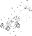
- a mower 100 mainly includes a handle device 11, a connecting rod 111, an operating member 112, an self-propelled operation trigger 112a, a body 12, and a traveling assembly 121.
- the body 12 includes the traveling assembly 121 and a power mechanism (not shown in the figure).
- the handle device 11 includes the connecting rod 111 and the operating member 112 that can be held.
- the operating member 112 includes at least a grip for the user to hold and the self-propelled operation trigger 112a
- the connecting rod 111 is a hollow long rod structure
- the connecting rod 111 connects the operating member 112 to the body 12.
- the traveling assembly 121 is mounted onto the body 12 and can rotate around a rotary shaft so that the entire mower 100 can move on the ground.
- the traveling assembly 121 includes traveling wheels 1211 of the mower 100 and a power mechanism for driving the traveling wheels 1211 to travel.
- the mower 100 has a self-propelled control function.
- the power mechanism can drive the traveling assembly 121 to rotate to drive the mower 100 to move on the ground so that the user does not need to manually push the mower 100 to move and mow.
- the power mechanism may be a traveling motor that can output a driving force for driving the traveling assembly 121 to rotate.
- the handle device 11 of the mower 100 is further integrated with a mowing operation trigger 112b.
- the mowing operation trigger 112b and the self-propelled operation trigger 112a of the mower 100 are all integrated into the operating member 112.
- the self-propelled operation trigger 112a is not limited to a physical switch or a signal switch, and any device that can control the current in a circuit to be on or off is applicable.
- the preceding self-propelled operation trigger 112a and/or the preceding mowing operation trigger 112b are not limited to current control and may also control the self-propelled function to be enabled or disabled by mechanical means.
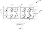
- a main control board 200 may be disposed on the body 12 or the handle device 11, and a control circuit 2000 on the main control board 200 can control at least the traveling and/or mowing of the mower 100.
- the control circuit 2000 may include at least a power interface 20, a controller 21, a first driver circuit 22, a traveling motor 23, a second driver circuit 24, and a cutting motor 25.
- the power interface 20 may be connected to a direct current (DC) power supply or an alternating current (AC) power supply.
- the control circuit 2000 may include a circuit capable of performing power conversion on the connected power supply.
- the control circuit 2000 may include a rectifier circuit, a filter circuit, or a voltage converter circuit capable of rectifying, filtering, or performing boost conversion, buck conversion, or other conversions on the power cord connected to the power interface 20.
- the mower 100 may include two or more power interfaces of the same or different types.
- the mower 100 may include two DC power interfaces connectable to at least two battery packs.
- the power interface 20 is used for connecting a battery pack 300 for a power tool.
- the battery pack 300 can supply power to the mower 100 and can also supply power to multiple power tools of different types.
- the rated voltage of the battery pack 300 is greater than or equal to 40 V, greater than or equal to 36 V, or greater than or equal to 50 V. This example does not specifically limit the appearance and structure of the battery pack 300.
- the power tool to which the battery pack 300 can supply power may be a handheld power tool, such as a drill, a hedge trimmer, or a sander.
- the power tool may be a table tool, such as a table saw or a miter saw.
- the power tool may be a riding power tool, such as a riding mower, a riding vehicle, or an all-terrain vehicle.
- the power tool may be a robotic tool, such as a robotic mower or a robotic snow thrower.
- the power tool may be an electric drill, an electric lamp, an electric vehicle, or the like.
- the power tool may be a garden tool, such as the hedge trimmer, a blower, or a chain saw.
- the power tool may be a decoration tool, such as a screwdriver, a nail gun, a circular saw, or the sander.
- the power tool may be a plant care tool, such as a grass trimmer, the hedge trimmer, or the chain saw.
- the power tool may be a cleaning tool, such as the blower, a snow thrower, or a washer.
- the power tool may be a drilling tool, such as the drill, the screwdriver, a wrench, or an electric hammer.
- the power tool may be a sawing tool, such as a reciprocating saw, a jigsaw, or the circular saw.
- the power tool may be a table tool, such as the table saw, the miter saw, a metal cutter, or an electric router.
- the power tool may be a sanding tool, such as an angle grinder or the sander.
- the power tool may be another tool, such as a lamp or a fan.
- the first driver circuit 22 is connected between the controller 21 and the traveling motor 23 and is used for driving the traveling motor 23 to operate.
- the first driver circuit 22 is electrically connected to stator windings of phases of the traveling motor 23 and is used for transmitting the power supply current to the stator windings to drive the traveling motor 23 to rotate.
- the first driver circuit 22 includes multiple switching elements Q1, Q2, Q3, Q4, Q5, and Q6. Gate terminals of the switching elements are electrically connected to the controller 21 and are used for receiving control signals from the controller 21. Drains or sources of the switching elements are connected to the stator windings of the traveling motor 23.
- the switching elements Q1 to Q6 receive the control signals from the controller 21 to change respective conduction states, thereby changing the current loaded to the stator windings of the traveling motor 23 by the power supply.
- the switching elements Q1 to Q6 in the first driver circuit 22 may be a three-phase bridge driver circuit including six controllable semiconductor power devices (such as field-effect transistors (FETs), bipolar junction transistors (BJTs), and insulated-gate bipolar transistors (IGBTs)) or any other types of solid-state switches (such as the IGBTs and the BJTs).
- FETs field-effect transistors
- BJTs bipolar junction transistors
- IGBTs insulated-gate bipolar transistors
- the second driver circuit 24 is connected between the controller 21 and the cutting motor 25 and is used for driving the cutting motor 25 to operate.
- the circuit structure and drive mode of the second driver circuit 24 reference may be made to the circuit structure and drive mode of the first driver circuit 22, and the details are not repeated here.
- the controller 21 can detect at least an operating signal generated after the handle device 11 is operated by the user and then control, according to the detected operating signal, the traveling motor 23 and/or the cutting motor 25 to operate. For example, after the user operates the handle device 11 to start the machine, the traveling motor 23 and/or the cutting motor 25 are powered on, and the controller 21 detects a thrust signal from the handle device 11 and then controls the traveling motor 23 to perform moving forward, turning, deceleration, acceleration, or other operations; or the controller 21 detects a mowing signal and controls the cutting motor 25 to operate so that the cutting blade cuts vegetation.
- the user may start the mower 100 by operating the handle device 11, which may include, for example, starting the traveling motor 23 so that the mower 100 starts to move, starting the cutting motor 25 so that the mower 100 starts to mow, or starting the two motors simultaneously so that the mower 100 moves while mowing.
- a start signal may be generated and transmitted to the controller 21, and the controller 21 can control the motor to start after recognizing the start signal, where the start signal may include a self-propelled start signal and a mowing start signal, and the controller 21 can distinguish between different start signals and control respective motors to start.
- a larger starting acceleration is generally set so that the traveling motor 23 or the cutting motor 25 can reach the set target speed in a short time.
- the starting acceleration of the motor is too large, the smoothness of the speed increase of the motor is reduced, and the operating feel of the user is reduced. If the starting acceleration of the motor is set to be smaller, the startup process is slow, and the requirement of the user for quick startup cannot be satisfied.
- the starting acceleration of the mower 100 may be controlled, thereby satisfying the requirement of the user for quick startup while ensuring the smoothness of the starting speed.
- the controller 21 in response to the start signal, can control the traveling motor 23 to accelerate to the target self-propelled speed with the variable self-propelled acceleration.
- the variable self-propelled acceleration may have at least one change process. For example, if the initial value of the self-propelled acceleration is a1, then during a process of starting the traveling motor 23, the self-propelled acceleration changes once and becomes a2, where a1 is greater than a2, or a1 is less than a2.
- the self-propelled acceleration may have two or more change processes.
- the condition for changing the self-propelled acceleration may be time, a speed threshold, or a combination of the two.
- the controller 21 may control the self-propelled acceleration to change every preset time or control the self-propelled acceleration to change once when the speed of the traveling motor 23 reaches a preset value.
- the user may operate the handle device 11 to change the self-propelled acceleration.
- variable mowing acceleration may have at least one change process. For example, if the initial value of the cutting acceleration is a3, then during a process of starting the cutting motor 25, the mowing acceleration changes once and becomes a4. In other examples, the mowing acceleration may have two or more change processes. In some examples, the condition for changing the mowing acceleration may be time, a speed threshold, or a combination of the two. For example, the controller 21 may control the mowing acceleration to change every preset time or control the mowing acceleration to change once when the speed of the cutting motor 25 reaches a preset value. In some examples, the user may operate the handle device 11 to change the mowing acceleration.
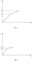
- the controller 21 may control the traveling motor 23 to accelerate to the first speed v1 with the first acceleration and based on the first speed, accelerate to the target self-propelled speed v2 with the second acceleration.
- the first acceleration is greater than the second acceleration.
- the traveling motor 23 is started with a larger starting acceleration, and when the starting speed reaches a certain value, the slope of the speed increase is reduced so that the traveling motor 23 at high speed can accelerate smoothly.
- the controller 21 may control the cutting motor 25 to accelerate to the third speed v3 with the third acceleration and based on the third speed, accelerate to the target cutting speed v4 with the fourth acceleration.
- the third acceleration is greater than the fourth acceleration.
- the cutting motor 25 is started with a larger starting acceleration, and when the starting speed reaches a certain value, the slope of the speed increase is reduced so that the cutting motor 25 at high speed can accelerate smoothly while the safe startup of the cutting motor 25 can be ensured.
- the mower 100 shown in FIG. 1 further includes an IoT module 27.
- the IoT module 27 may be disposed on the main control board 200, or may be disposed on the handle device 11, or may be detachably mounted on the mower 100, or can communicate with at least the main control board 200.
- the mower 100 can communicate with an external terminal 300 through the IoT module 27 and acquire the communication data sent by the external terminal 300.
- the external terminal 300 may be a smartphone, a smartwatch, a tablet computer, a virtual reality (VR)/augmented reality (AR) device, a drone, or the like.
- the smartphone is used as an example for the description in the present application.
- the IoT module 27 may support at least one of wired communication technology and wireless communication technology.
- the IoT module 27 supports at least one of transmission access, network switching, mobile communications, wireless communications, optical communications, satellite communications, support management, and private network communications.
- the IoT module 27 supports at least one of cellular network technology, wireless LAN technology, wireless PAN technology, satellite communication technology, infrared communication technology, optical fiber communication technology, Bluetooth LE technology, LoRa technology, Wi-Fi, and Zigbee.
- the cellular network technology may include mobile communication technologies such as 2G, 3G, 4G, and 5G and standards such as code-division multiple access (CDMA), the Global System for Mobile Communications (GSM), time division-synchronous code division multiple access (TD-SCDMA), wide code division multiple access (WCDMA), and long-term evolution (LTE).
- CDMA code-division multiple access
- GSM Global System for Mobile Communications
- TD-SCDMA time division-synchronous code division multiple access
- WCDMA wide code division multiple access
- LTE long-term evolution
- the wireless LAN technology may include Wi-Fi, Bluetooth, ZigBee, and other technologies and is used for wireless communication within the LAN.
- the wireless PAN technology may include near-field communication (NFC), radio-frequency identification (RFID), and other technologies and is used for short-range wireless communication.
- the satellite communication technology may include satellite phones, satellite televisions (TVs), satellite navigation, and other technologies and is used for long-range wireless communication.
- the infrared communication technology may include infrared remote control, infrared data transmission, and other technologies and is used for short-range wireless communication.
- the optical fiber communication technology may include optical fiber communication, optical fiber sensing, and other technologies and is used for high-speed long-range wireless communication.
- the LoRa technology is an ultra-long-range wireless transmission solution based on spread spectrum technology.
- the user may send at least startup setting data to the IoT module 27 by operating the intelligent terminal 300.
- the controller 21 may communicate with the IoT module 27 to acquire the startup setting data and may adjust at least the self-propelled acceleration and/or the mowing acceleration according to the startup setting data. That is to say, the startup setting data includes at least setting data for the starting acceleration.
- the startup setting data may include data set for the startup time, startup mode, startup power, or the like.
- the user may send the startup setting data to the mower 100 before the mower 100 is started or may send the startup setting data to the mower 100 during a process of starting the mower 100. That is to say, the user may set the starting acceleration according to the usage requirements before the mower 100 travels and/or mows or change the starting acceleration during the process of starting the mower 100. For example, during the process of starting the mower 100, if the user perceives that the starting speed of the traveling motor 23 is relatively small, then the user may increase the self-propelled acceleration through the intelligent terminal; and if the user perceives that the starting speed of the traveling motor 23 is relatively large, then the user may reduce the self-propelled acceleration through the intelligent terminal.
- the control interface for the mower 100 may be displayed in the terminal application, or at least the starting acceleration adjustment interface for different motors may be displayed.
- triangular adjustment buttons for the self-propelled acceleration and the mowing acceleration are provided under the icons of the traveling motor 23 and the cutting motor 25, respectively, and the user may increase or decrease the self-propelled acceleration or the mowing acceleration by touching the adjustment buttons.
- the amplitude of the acceleration adjusted by the adjustment button is fixed. For example, the speed increases by 1 m/s each time.
- a user input box may be directly set in a display interface, and the user may directly input any starting acceleration value that does not exceed the range satisfying the safety regulations of the mower 100.
- the intelligent terminal 300 may use any other display control interface that is easy to understand and operate, and the display control interface is not shown in detail here.
- the controller 21 may adjust the first acceleration of the traveling motor 23 during starting according to the acquired startup setting data for the traveling motor 23 so that the traveling motor 23 can accelerate to the first speed faster; or the controller 21 may adjust the second acceleration of the traveling motor 23 so that the speed increase of the traveling motor 23 at a high-speed startup stage is smoother.
- the controller 21 may adjust the third acceleration of the cutting motor 25 during starting according to the acquired startup setting data for the cutting motor 25 so that the cutting motor 25 can accelerate to the third speed faster; or the controller 21 may adjust the fourth acceleration of the cutting motor 25 so that the speed increase of the cutting motor 25 at a high-speed startup stage is smoother.
- the controller 21 may include at least a data storage unit and a control unit, where the data storage unit may acquire and store the startup setting data, and the control unit is configured to adjust at least the self-propelled acceleration and/or the mowing acceleration according to the startup setting data.
- the data storage unit may store all historical startup setting data or store at least the last used historical startup setting data, and the control unit may set the self-propelled acceleration and/or the mowing acceleration of the currently started mower 100 according to the historical startup setting data. In this manner, the user's usage habits can be well retained, or at least the user's habit of starting the mower 100 can be retained.
- the user may adjust different working parameters of the started mower 100 through the intelligent terminal 300.
- the user may adjust the normal traveling speed of the mower 100, the normal mowing rotational speed, the traveling direction, or the like, not all of which are listed one by one here.
- the user may reset the function of part of the operating member 112 in the mower 100 through the intelligent terminal 300.
- the user may redefine the self-propelled operation trigger 112a as the mowing operation trigger 112b and redefine the mowing operation trigger 112b as the self-propelled operation trigger 112a. That is to say, the user may interchange the positions of the self-propelled operation trigger 112a and the mowing operation trigger 112b according to personal usage habits.
- a trigger switching mechanism (not shown) may be disposed in the mower 100, and the user may directly operate the trigger switching mechanism to interchange the positions of the self-propelled operation trigger 112a and the mowing operation trigger 112b.
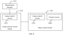
- the mower 100 further includes an illumination assembly 122, and the illumination assembly 122 includes at least an illumination element 1221 and a light switch (not shown) disposed on the handle device 11.
- the illumination element 1221 may be driven by a lamp control circuit 1222, and the lamp control circuit 1222 is disposed on a lamp control circuit board 1223.
- the lamp control circuit board 1223 may be disposed below the illumination element 1221 or near the illumination element 1221. Bus communication or other communication methods such as carrier communication may be used between the lamp control circuit board 1223 and the main control board 200.
- the control circuit 2000 on the main control board 200 can communicate with at least the lamp control circuit 1222.
- the lamp control circuit 1222 is disposed separately on the lamp control circuit board 1223, thereby reducing the heat generated by the main control board 200.
- the lamp control circuit board 1223 may communicate with the main control board 200 through a bus.
- the number of components disposed on the lamp control circuit board 1223 is reduced so that the following is avoided: the lamp control circuit board 1223 disposed near the illumination element 1221 is affected by the heat generated due to the light emission of the illumination element 1221, and the service life of part of the components in the lamp control circuit 1222 is reduced.
Landscapes
- Life Sciences & Earth Sciences (AREA)
- Environmental Sciences (AREA)
- Engineering & Computer Science (AREA)
- Computer Networks & Wireless Communication (AREA)
- Signal Processing (AREA)
- Physics & Mathematics (AREA)
- General Physics & Mathematics (AREA)
- Harvester Elements (AREA)
Abstract
Description
- The present disclosure relates to garden tools, for example, a push working machine and mower.
- In a self-propelled garden tool such as a push mower or a push snow thrower, an operating member is generally disposed on the handle and used for a user to control the operation states of a traveling motor and a working motor of the machine.
- The user can start the mower through the operating member such that the mower travels and/or mows. During the process of starting the mower, the user can control the process of starting the mower and can control at least the starting speed or the change in speed.
- This part provides background information related to the present application, which is not necessarily the existing art.
- The present application aims to solve or at least alleviate part or all of the preceding problems. For this reason, an object of the present application is to provide a mower with variable starting acceleration.
- To achieve the preceding object, the present application adopts the technical solutions below.
- A push working machine includes a body including at least a traveling assembly, a traveling motor driving the traveling assembly, a functional assembly, and a functional motor driving the functional assembly; a handle device connected to the body and including at least an operating member for a user to operate; a controller configured to control at least the working states of the traveling motor and the functional motor; and a power interface for connecting electrical energy capable of supplying power to at least the traveling motor and the functional motor. The controller is configured to, in response to a start signal, be capable of controlling the traveling motor to accelerate to the first speed with the first acceleration and accelerate to the target self-propelled speed with the second acceleration.
- In an example, the second acceleration is less than the first acceleration.
- In an example, the push working machine further includes an Internet of Things (IoT) module configured to be connected to at least the controller and capable of transmitting communication data to the controller.
- In an example, an IoT module is configured to communicate with an external terminal and acquire startup setting data sent by the external terminal.
- In an example, the controller is configured to acquire the startup setting data and adjust at least the first acceleration and/or the second acceleration according to the startup setting data.
- In an example, the IoT module supports at least one of wired communication technology and wireless communication technology.
- In an example, the IoT module supports at least one of transmission access, network switching, mobile communications, wireless communications, optical communications, satellite communications, support management, and private network communications.
- In an example, the IoT module supports at least one of cellular network technology, wireless local area network (LAN) technology, wireless personal area network (PAN) technology, satellite communication technology, infrared communication technology, optical fiber communication technology, Bluetooth Low Energy (Bluetooth LE) technology, long range (LoRa) technology, Wi-Fi, and Zigbee.
- In an example, the controller is configured to acquire the startup setting data and adjust the first acceleration and/or the second acceleration according to the startup setting data.
- In an example, the controller includes a data storage unit configured to store historical startup setting data.
- In an example, the controller further includes a control unit configured to set the first acceleration and/or the second acceleration according to the historical startup setting data.
- A push self-propelled mower includes a body including at least a traveling assembly, a traveling motor driving the traveling assembly, a cutting assembly, and a cutting motor driving the cutting assembly; a handle device connected to the body and including at least an operating member for a user to operate; a controller configured to control at least the working states of the traveling motor and the cutting motor; and a power interface for connecting electrical energy capable of supplying power to at least the traveling motor and the cutting motor. The controller is configured to, in response to a start signal, be capable of controlling the traveling motor to accelerate to the target self-propelled speed with at least two different accelerations.
- In an example, the push mower further includes an IoT module configured to be connected to at least the controller and capable of transmitting communication data to the controller.
- In an example, an IoT module is configured to communicate with an external terminal and acquire startup setting data sent by the external terminal.
- In an example, the controller is configured to acquire the startup setting data and adjust the acceleration according to the startup setting data.
- A push mower includes a body including at least a traveling assembly, a traveling motor driving the traveling assembly, a cutting assembly, and a cutting motor driving the cutting assembly; a handle device connected to the body and including at least an operating member for a user to operate; a controller configured to control at least the working states of the traveling motor and the cutting motor; and a power interface for connecting electrical energy capable of supplying power to at least the traveling motor and the cutting motor. The controller is configured to, in response to a self-propelled start signal, be capable of controlling the traveling motor to accelerate to the target self-propelled speed with the variable self-propelled acceleration; or in response to a mowing start signal, be capable of controlling the cutting motor to accelerate to the target mowing speed with the variable mowing acceleration.
- In an example, the self-propelled acceleration includes at least the first acceleration and the second acceleration, where the first acceleration is greater than the second acceleration; and the mowing acceleration includes at least the third acceleration and the fourth acceleration, where the third acceleration is greater than the fourth acceleration.
- In an example, the push mower further includes an IoT module configured to be connected to at least the controller and capable of transmitting communication data to the controller.
- In an example, the IoT module is configured to communicate with an external terminal and acquire startup setting data sent by the external terminal.
- In an example, the controller is configured to acquire the startup setting data and adjust the self-propelled acceleration and/or the mowing acceleration according to the startup setting data.
- In an example, the controller includes a data storage unit configured to store historical startup setting data.
- In an example, the controller further includes a control unit configured to set the self-propelled acceleration and/or the mowing acceleration according to the historical startup setting data.
- A push mower includes a body including at least a traveling assembly, a traveling motor driving the traveling assembly, a cutting assembly, and a cutting motor driving the cutting assembly; a handle device connected to the body and including at least an operating member for a user to operate; and a control circuit configured to control at least the operation of the traveling motor and/or the cutting motor. The push mower further includes an illumination assembly including an illumination element and a light switch for the user to operate to control the illumination element; and a lamp control circuit configured to control a working state of the illumination element. At least part of the lamp control circuit and the control circuit are not disposed on the same control circuit board.
- In an example, the lamp control circuit is disposed on a lamp control circuit board, and the control circuit is disposed on a main control board.
- In an example, the lamp control circuit board communicates with the main control board through a bus.
- In an example, at least a power component in the lamp control circuit is disposed on the main control board.
- To illustrate technical solutions in examples of the present application more clearly, drawings used in the description of the examples are briefly described below. Apparently, the drawings described below illustrate only part of the examples of the present application, and those of ordinary skill in the art may obtain other drawings based on the drawings described below on the premise that no creative work is done.
-
FIG. 1 is a structural view of a mower according to an example of the present application. -
FIG. 2 is a schematic diagram of a control circuit of the mower inFIG. 1 . -
FIG. 3 is a schematic diagram illustrating a variation curve of speed during a process of starting a self-propelled motor in an example of the present application. -
FIG. 4 is a schematic diagram illustrating a variation curve of speed during a process of starting a cutting motor in an example of the present application. -
FIG. 5 is a schematic view of a mower system in an example of the present application. -
FIG. 6 is a schematic view of an intelligent terminal display interface in an example of the present application. -
FIG. 7 is a schematic diagram illustrating the position of a lamp control circuit on a control board in an example of the present application. -
FIG. 8 is a schematic diagram illustrating the position of a lamp control circuit on a control board in an example of the present application. - Before any example of the present application is explained in detail, it is to be understood that the present application is not limited to the application in the structural details and arrangement of components set forth in the following description or shown in the preceding drawings.
- In the present application, the term "comprising", "including", "having", or any other variant thereof is intended to encompass a non-exclusive inclusion so that a process, method, article, or apparatus that includes a series of elements not only includes those elements but also includes other elements that are not expressly listed or further includes elements that are inherent to such a process, method, article, or apparatus. In the absence of more limitations, an element defined by the statement "including a ..." does not exclude the presence of additional identical elements in a process, method, article, or device including the element.
- In the present application, the term "and/or" is an association relationship describing associated objects and indicates that three relationships may exist. For example, A and/or B may indicate that A exists alone, both A and B exist, and B exists alone. In addition, in the present application, the character "/" generally indicates an "and/or" relationship between associated objects before and after the character "/".
- In the present application, the term "connected", "combined", "coupled", or "mounted" may be directly "connected", "combined", "coupled", or "mounted" and may also be indirectly "connected", "combined", "coupled", or "mounted". For example, the direct connection indicates that two parts or assemblies are connected together without an intermediate piece, and the indirect connection indicates that two parts or assemblies are separately connected to at least one intermediate piece and the two parts or assemblies are connected through the intermediate piece. Furthermore, "connected" and "coupled" are not limited to physical or mechanical connections or couplings and may include electrical connections or couplings.
- In the present application, it is to be understood by those of ordinary skill in the art that a relative term (for example, "about", "approximately", or "basically") used in conjunction with quantities or conditions is inclusive of the stated value and has the meaning indicated by the context. For example, the relative term includes at least the degree of error associated with the measurement of a particular value, the tolerance resulting from manufacturing, assembly, and usage and associated with a particular value, and the like. Such a term is to be construed as disclosing a range defined by the absolute values of two endpoints. The relative term may refer to plus or minus a certain percentage (such as 1%, 5%, 10%, or more) of an indicated value. A value not modified by the relative term should also be disclosed as a particular value with a tolerance. In addition, when expressing a relative angular position relationship (for example, basically parallel or basically perpendicular), "basically" may refer to plus or minus a certain degree (such as 1 degree, 5 degrees, 10 degrees, or more) based on an indicated angle.
- In the present application, it is to be understood by those of ordinary skill in the art that the function implemented by an assembly may be implemented by one assembly, multiple assemblies, one part, or multiple parts. Similarly, the function implemented by a part may be implemented by one part, one assembly, or a combination of multiple parts.
- In the present application, the terms "upper", "lower", "left", "right", "front", "rear", and other orientation words are described by the orientations and position relations shown in the drawings and should not be understood as a limitation to the examples of the present application. In addition, in the context, it is to be understood that when an element is connected "above" or "below" another element, the element not only can be directly connected "above" or "below" another element but also can be indirectly connected "above" or "below" another element through an intermediate element. It is also to be understood that orientation words such as an upper side, a lower side, a left side, a right side, a front side, and a rear side not only represent positive orientations but also may be understood as lateral orientations. For example, the term "below" may refer to "directly below", "on a lower left", "on a lower right", "on a front lower side", "on a rear lower side", and the like.
- In the present application, the terms "controller", "processor", "central processing unit", "central processing unit (CPU)", and "microcontroller unit (MCU)" are interchangeable. Where a unit such as the "controller", the "processor", the "central processing unit", the "CPU", or the "MCU" is used to implement specific functions, these functions may be implemented by a single one of the preceding units or multiple preceding units unless otherwise indicated.
- In the present application, the term "device", "module", or "unit" is used to implement a specific function in the form of hardware or software.
- In the present application, the terms "computing", "judging", "controlling", "determining", "identifying", and the like refer to the operations and processes of a computer system or similar electronic computing device (for example, the controller, the processor, or the like).
- In addition to a mower, a push working machine in the present application may also include a push snow thrower, a push warehouse trailer, a picnic trolley, a power trailer, or another self-propelled electrical device. A push mower that can be operated by a user from the rear side of the push device is used as an example for the description below. A functional assembly in the push working machine may be a cutting assembly. For example, the cutting assembly includes a cutting blade or a cutting deck. A functional motor may be understood as a cutting motor.
- Referring to
FIG. 1 , amower 100 mainly includes a handle device 11, a connectingrod 111, an operatingmember 112, an self-propelledoperation trigger 112a, abody 12, and a travelingassembly 121. Thebody 12 includes the travelingassembly 121 and a power mechanism (not shown in the figure). Optionally, the handle device 11 includes the connectingrod 111 and the operatingmember 112 that can be held. The operatingmember 112 includes at least a grip for the user to hold and the self-propelledoperation trigger 112a, the connectingrod 111 is a hollow long rod structure, and the connectingrod 111 connects the operatingmember 112 to thebody 12. The travelingassembly 121 is mounted onto thebody 12 and can rotate around a rotary shaft so that theentire mower 100 can move on the ground. In this example, the travelingassembly 121 includes travelingwheels 1211 of themower 100 and a power mechanism for driving the travelingwheels 1211 to travel. - In this example, the
mower 100 has a self-propelled control function. The power mechanism can drive the travelingassembly 121 to rotate to drive themower 100 to move on the ground so that the user does not need to manually push themower 100 to move and mow. Specifically, the power mechanism may be a traveling motor that can output a driving force for driving the travelingassembly 121 to rotate. In some examples, the handle device 11 of themower 100 is further integrated with amowing operation trigger 112b. For example, the mowingoperation trigger 112b and the self-propelledoperation trigger 112a of themower 100 are all integrated into the operatingmember 112. In addition, the self-propelledoperation trigger 112a is not limited to a physical switch or a signal switch, and any device that can control the current in a circuit to be on or off is applicable. In fact, the preceding self-propelledoperation trigger 112a and/or the precedingmowing operation trigger 112b are not limited to current control and may also control the self-propelled function to be enabled or disabled by mechanical means. - A
main control board 200 may be disposed on thebody 12 or the handle device 11, and acontrol circuit 2000 on themain control board 200 can control at least the traveling and/or mowing of themower 100. As shown inFIG. 2 , thecontrol circuit 2000 may include at least apower interface 20, acontroller 21, afirst driver circuit 22, a travelingmotor 23, asecond driver circuit 24, and a cuttingmotor 25. - The
power interface 20 may be connected to a direct current (DC) power supply or an alternating current (AC) power supply. Thecontrol circuit 2000 may include a circuit capable of performing power conversion on the connected power supply. For example, thecontrol circuit 2000 may include a rectifier circuit, a filter circuit, or a voltage converter circuit capable of rectifying, filtering, or performing boost conversion, buck conversion, or other conversions on the power cord connected to thepower interface 20. It is to be understood that themower 100 may include two or more power interfaces of the same or different types. For example, themower 100 may include two DC power interfaces connectable to at least two battery packs. In this example, thepower interface 20 is used for connecting abattery pack 300 for a power tool. That is to say, thebattery pack 300 can supply power to themower 100 and can also supply power to multiple power tools of different types. For example, the rated voltage of thebattery pack 300 is greater than or equal to 40 V, greater than or equal to 36 V, or greater than or equal to 50 V. This example does not specifically limit the appearance and structure of thebattery pack 300. - In some examples, the power tool to which the
battery pack 300 can supply power may be a handheld power tool, such as a drill, a hedge trimmer, or a sander. Alternatively, the power tool may be a table tool, such as a table saw or a miter saw. Alternatively, the power tool may be a riding power tool, such as a riding mower, a riding vehicle, or an all-terrain vehicle. Alternatively, the power tool may be a robotic tool, such as a robotic mower or a robotic snow thrower. In some examples, the power tool may be an electric drill, an electric lamp, an electric vehicle, or the like. In some examples, the power tool may be a garden tool, such as the hedge trimmer, a blower, or a chain saw. Alternatively, the power tool may be a decoration tool, such as a screwdriver, a nail gun, a circular saw, or the sander. In some examples, the power tool may be a plant care tool, such as a grass trimmer, the hedge trimmer, or the chain saw. Alternatively, the power tool may be a cleaning tool, such as the blower, a snow thrower, or a washer. Alternatively, the power tool may be a drilling tool, such as the drill, the screwdriver, a wrench, or an electric hammer. Alternatively, the power tool may be a sawing tool, such as a reciprocating saw, a jigsaw, or the circular saw. Alternatively, the power tool may be a table tool, such as the table saw, the miter saw, a metal cutter, or an electric router. Alternatively, the power tool may be a sanding tool, such as an angle grinder or the sander. Alternatively, the power tool may be another tool, such as a lamp or a fan. - The
first driver circuit 22 is connected between thecontroller 21 and the travelingmotor 23 and is used for driving the travelingmotor 23 to operate. In an example, thefirst driver circuit 22 is electrically connected to stator windings of phases of the travelingmotor 23 and is used for transmitting the power supply current to the stator windings to drive the travelingmotor 23 to rotate. As an example, as shown inFIG. 2 , thefirst driver circuit 22 includes multiple switching elements Q1, Q2, Q3, Q4, Q5, and Q6. Gate terminals of the switching elements are electrically connected to thecontroller 21 and are used for receiving control signals from thecontroller 21. Drains or sources of the switching elements are connected to the stator windings of the travelingmotor 23. The switching elements Q1 to Q6 receive the control signals from thecontroller 21 to change respective conduction states, thereby changing the current loaded to the stator windings of the travelingmotor 23 by the power supply. In an example, the switching elements Q1 to Q6 in thefirst driver circuit 22 may be a three-phase bridge driver circuit including six controllable semiconductor power devices (such as field-effect transistors (FETs), bipolar junction transistors (BJTs), and insulated-gate bipolar transistors (IGBTs)) or any other types of solid-state switches (such as the IGBTs and the BJTs). - The
second driver circuit 24 is connected between thecontroller 21 and the cuttingmotor 25 and is used for driving the cuttingmotor 25 to operate. For the circuit structure and drive mode of thesecond driver circuit 24, reference may be made to the circuit structure and drive mode of thefirst driver circuit 22, and the details are not repeated here. - The
controller 21 can detect at least an operating signal generated after the handle device 11 is operated by the user and then control, according to the detected operating signal, the travelingmotor 23 and/or the cuttingmotor 25 to operate. For example, after the user operates the handle device 11 to start the machine, the travelingmotor 23 and/or the cuttingmotor 25 are powered on, and thecontroller 21 detects a thrust signal from the handle device 11 and then controls the travelingmotor 23 to perform moving forward, turning, deceleration, acceleration, or other operations; or thecontroller 21 detects a mowing signal and controls the cuttingmotor 25 to operate so that the cutting blade cuts vegetation. - In an example, the user may start the
mower 100 by operating the handle device 11, which may include, for example, starting the travelingmotor 23 so that themower 100 starts to move, starting the cuttingmotor 25 so that themower 100 starts to mow, or starting the two motors simultaneously so that themower 100 moves while mowing. For example, when the user operates the handle device 11, a start signal may be generated and transmitted to thecontroller 21, and thecontroller 21 can control the motor to start after recognizing the start signal, where the start signal may include a self-propelled start signal and a mowing start signal, and thecontroller 21 can distinguish between different start signals and control respective motors to start. - In the existing art, to quickly start the mower, a larger starting acceleration is generally set so that the traveling
motor 23 or the cuttingmotor 25 can reach the set target speed in a short time. However, if the starting acceleration of the motor is too large, the smoothness of the speed increase of the motor is reduced, and the operating feel of the user is reduced. If the starting acceleration of the motor is set to be smaller, the startup process is slow, and the requirement of the user for quick startup cannot be satisfied. - In the example of the present application, the starting acceleration of the
mower 100 may be controlled, thereby satisfying the requirement of the user for quick startup while ensuring the smoothness of the starting speed. - In an example, in response to the start signal, the
controller 21 can control the travelingmotor 23 to accelerate to the target self-propelled speed with the variable self-propelled acceleration. In an example, the variable self-propelled acceleration may have at least one change process. For example, if the initial value of the self-propelled acceleration is a1, then during a process of starting the travelingmotor 23, the self-propelled acceleration changes once and becomes a2, where a1 is greater than a2, or a1 is less than a2. In other examples, the self-propelled acceleration may have two or more change processes. In some examples, the condition for changing the self-propelled acceleration may be time, a speed threshold, or a combination of the two. For example, thecontroller 21 may control the self-propelled acceleration to change every preset time or control the self-propelled acceleration to change once when the speed of the travelingmotor 23 reaches a preset value. In some examples, the user may operate the handle device 11 to change the self-propelled acceleration. - In an example, the variable mowing acceleration may have at least one change process. For example, if the initial value of the cutting acceleration is a3, then during a process of starting the cutting
motor 25, the mowing acceleration changes once and becomes a4. In other examples, the mowing acceleration may have two or more change processes. In some examples, the condition for changing the mowing acceleration may be time, a speed threshold, or a combination of the two. For example, thecontroller 21 may control the mowing acceleration to change every preset time or control the mowing acceleration to change once when the speed of the cuttingmotor 25 reaches a preset value. In some examples, the user may operate the handle device 11 to change the mowing acceleration. - In this example, referring to the variation curve of the speed of the traveling
motor 23 shown inFIG. 3 , thecontroller 21 may control the travelingmotor 23 to accelerate to the first speed v1 with the first acceleration and based on the first speed, accelerate to the target self-propelled speed v2 with the second acceleration. The first acceleration is greater than the second acceleration. In the early stage of startup, the travelingmotor 23 is started with a larger starting acceleration, and when the starting speed reaches a certain value, the slope of the speed increase is reduced so that the travelingmotor 23 at high speed can accelerate smoothly. Referring to the variation curve of the speed of the cuttingmotor 25 shown inFIG. 4 , thecontroller 21 may control the cuttingmotor 25 to accelerate to the third speed v3 with the third acceleration and based on the third speed, accelerate to the target cutting speed v4 with the fourth acceleration. The third acceleration is greater than the fourth acceleration. In the early stage of startup, the cuttingmotor 25 is started with a larger starting acceleration, and when the starting speed reaches a certain value, the slope of the speed increase is reduced so that the cuttingmotor 25 at high speed can accelerate smoothly while the safe startup of the cuttingmotor 25 can be ensured. - The
mower 100 shown inFIG. 1 further includes anIoT module 27. TheIoT module 27 may be disposed on themain control board 200, or may be disposed on the handle device 11, or may be detachably mounted on themower 100, or can communicate with at least themain control board 200. Referring to amower system 1000 shown inFIG. 5 , themower 100 can communicate with anexternal terminal 300 through theIoT module 27 and acquire the communication data sent by theexternal terminal 300. - In this example, the
external terminal 300 may be a smartphone, a smartwatch, a tablet computer, a virtual reality (VR)/augmented reality (AR) device, a drone, or the like. The smartphone is used as an example for the description in the present application. - The
IoT module 27 may support at least one of wired communication technology and wireless communication technology. In an example, theIoT module 27 supports at least one of transmission access, network switching, mobile communications, wireless communications, optical communications, satellite communications, support management, and private network communications. In an example, theIoT module 27 supports at least one of cellular network technology, wireless LAN technology, wireless PAN technology, satellite communication technology, infrared communication technology, optical fiber communication technology, Bluetooth LE technology, LoRa technology, Wi-Fi, and Zigbee. The cellular network technology may include mobile communication technologies such as 2G, 3G, 4G, and 5G and standards such as code-division multiple access (CDMA), the Global System for Mobile Communications (GSM), time division-synchronous code division multiple access (TD-SCDMA), wide code division multiple access (WCDMA), and long-term evolution (LTE). The wireless LAN technology may include Wi-Fi, Bluetooth, ZigBee, and other technologies and is used for wireless communication within the LAN. The wireless PAN technology may include near-field communication (NFC), radio-frequency identification (RFID), and other technologies and is used for short-range wireless communication. The satellite communication technology may include satellite phones, satellite televisions (TVs), satellite navigation, and other technologies and is used for long-range wireless communication. The infrared communication technology may include infrared remote control, infrared data transmission, and other technologies and is used for short-range wireless communication. The optical fiber communication technology may include optical fiber communication, optical fiber sensing, and other technologies and is used for high-speed long-range wireless communication. The LoRa technology is an ultra-long-range wireless transmission solution based on spread spectrum technology. - The user may send at least startup setting data to the
IoT module 27 by operating theintelligent terminal 300. Thecontroller 21 may communicate with theIoT module 27 to acquire the startup setting data and may adjust at least the self-propelled acceleration and/or the mowing acceleration according to the startup setting data. That is to say, the startup setting data includes at least setting data for the starting acceleration. In other examples, the startup setting data may include data set for the startup time, startup mode, startup power, or the like. - In this example, the user may send the startup setting data to the
mower 100 before themower 100 is started or may send the startup setting data to themower 100 during a process of starting themower 100. That is to say, the user may set the starting acceleration according to the usage requirements before themower 100 travels and/or mows or change the starting acceleration during the process of starting themower 100. For example, during the process of starting themower 100, if the user perceives that the starting speed of the travelingmotor 23 is relatively small, then the user may increase the self-propelled acceleration through the intelligent terminal; and if the user perceives that the starting speed of the travelingmotor 23 is relatively large, then the user may reduce the self-propelled acceleration through the intelligent terminal. - In an example, after the
intelligent terminal 300 establishes a communication connection with themower 100, the control interface for themower 100 may be displayed in the terminal application, or at least the starting acceleration adjustment interface for different motors may be displayed. As shown inFIG. 6 , triangular adjustment buttons for the self-propelled acceleration and the mowing acceleration are provided under the icons of the travelingmotor 23 and the cuttingmotor 25, respectively, and the user may increase or decrease the self-propelled acceleration or the mowing acceleration by touching the adjustment buttons. In an example, the amplitude of the acceleration adjusted by the adjustment button is fixed. For example, the speed increases by 1 m/s each time. In other examples, a user input box may be directly set in a display interface, and the user may directly input any starting acceleration value that does not exceed the range satisfying the safety regulations of themower 100. Theintelligent terminal 300 may use any other display control interface that is easy to understand and operate, and the display control interface is not shown in detail here. - The
controller 21 may adjust the first acceleration of the travelingmotor 23 during starting according to the acquired startup setting data for the travelingmotor 23 so that the travelingmotor 23 can accelerate to the first speed faster; or thecontroller 21 may adjust the second acceleration of the travelingmotor 23 so that the speed increase of the travelingmotor 23 at a high-speed startup stage is smoother. Alternatively, thecontroller 21 may adjust the third acceleration of the cuttingmotor 25 during starting according to the acquired startup setting data for the cuttingmotor 25 so that the cuttingmotor 25 can accelerate to the third speed faster; or thecontroller 21 may adjust the fourth acceleration of the cuttingmotor 25 so that the speed increase of the cuttingmotor 25 at a high-speed startup stage is smoother. - In an example, the
controller 21 may include at least a data storage unit and a control unit, where the data storage unit may acquire and store the startup setting data, and the control unit is configured to adjust at least the self-propelled acceleration and/or the mowing acceleration according to the startup setting data. In this example, the data storage unit may store all historical startup setting data or store at least the last used historical startup setting data, and the control unit may set the self-propelled acceleration and/or the mowing acceleration of the currently startedmower 100 according to the historical startup setting data. In this manner, the user's usage habits can be well retained, or at least the user's habit of starting themower 100 can be retained. - In other examples, the user may adjust different working parameters of the started
mower 100 through theintelligent terminal 300. For example, the user may adjust the normal traveling speed of themower 100, the normal mowing rotational speed, the traveling direction, or the like, not all of which are listed one by one here. - In some examples, the user may reset the function of part of the operating
member 112 in themower 100 through theintelligent terminal 300. For example, through theintelligent terminal 300, the user may redefine the self-propelledoperation trigger 112a as the mowingoperation trigger 112b and redefine themowing operation trigger 112b as the self-propelledoperation trigger 112a. That is to say, the user may interchange the positions of the self-propelledoperation trigger 112a and themowing operation trigger 112b according to personal usage habits. In some examples, a trigger switching mechanism (not shown) may be disposed in themower 100, and the user may directly operate the trigger switching mechanism to interchange the positions of the self-propelledoperation trigger 112a and themowing operation trigger 112b. - With continued reference to
FIG. 1 , themower 100 further includes anillumination assembly 122, and theillumination assembly 122 includes at least anillumination element 1221 and a light switch (not shown) disposed on the handle device 11. By operating the light switch, the user may control theillumination element 1221 to be turned on or off or control the illumination brightness of theillumination element 1221. Referring toFIG. 7 , theillumination element 1221 may be driven by alamp control circuit 1222, and thelamp control circuit 1222 is disposed on a lampcontrol circuit board 1223. The lampcontrol circuit board 1223 may be disposed below theillumination element 1221 or near theillumination element 1221. Bus communication or other communication methods such as carrier communication may be used between the lampcontrol circuit board 1223 and themain control board 200. Thecontrol circuit 2000 on themain control board 200 can communicate with at least thelamp control circuit 1222. In this example, thelamp control circuit 1222 is disposed separately on the lampcontrol circuit board 1223, thereby reducing the heat generated by themain control board 200. - In an example, referring to
FIG. 8 , at least some of the components in thelamp control circuit 1222 are disposed on themain control board 200, other components are disposed on the lampcontrol circuit board 1223, and the lampcontrol circuit board 1223 may communicate with themain control board 200 through a bus. The number of components disposed on the lampcontrol circuit board 1223 is reduced so that the following is avoided: the lampcontrol circuit board 1223 disposed near theillumination element 1221 is affected by the heat generated due to the light emission of theillumination element 1221, and the service life of part of the components in thelamp control circuit 1222 is reduced. - The basic principles, main features, and advantages of the present application are shown and described above. It is to be understood by those skilled in the art that the preceding examples do not limit the present application in any form, and all technical solutions obtained through equivalent substitutions or equivalent transformations fall within the scope of the present application.
Claims (14)
- A push working machine (100), comprising:a body (12) comprising at least a traveling assembly (121), a traveling motor (23) driving the traveling assembly, a functional assembly, and a functional motor (25) driving the functional assembly;a handle device (11) connected to the body and comprising at least an operating member (112) for a user to operate;a controller (21) configured to control at least working states of the traveling motor and the functional motor; anda power interface (20) for connecting electrical energy capable of supplying power to at least the traveling motor and the functional motor;wherein the controller is configured to:
in response to a start signal, be capable of controlling the traveling motor to accelerate to a first speed with a first acceleration and accelerate to a target self-propelled speed with a second acceleration. - The push working machine of claim 1, wherein the second acceleration is less than the first acceleration.
- The push working machine of claim 1, further comprising an Internet of Things (IoT) module (27) configured to be connected to at least the controller and capable of transmitting communication data to the controller.
- The push working machine of claim 3, wherein the IoT module is configured to communicate with an external terminal (300) and acquire startup setting data sent by the external terminal.
- The push working machine of claim 4, wherein the controller is configured to acquire the startup setting data and adjust at least the first acceleration and/or the second acceleration according to the startup setting data.
- The push working machine of claim 3, wherein the loT module supports at least one of wired communication technology or wireless communication technology.
- The push working machine of claim 3, wherein the loT module supports at least one of transmission access, network switching, mobile communications, wireless communications, optical communications, satellite communications, support management, or private network communications.
- The push working machine of claim 3, wherein the IoT module supports at least one of cellular network technology, wireless local area network (LAN) technology, wireless personal area network (PAN) technology, satellite communication technology, infrared communication technology, optical fiber communication technology, Bluetooth Low Energy (Bluetooth LE) technology, long range (LoRa) technology, Wi-Fi, or Zigbee.
- The push working machine of claim 1, wherein the controller comprises a data storage unit configured to store historical startup setting data.
- The push working machine of claim 1, wherein the controller further comprises a control unit configured to set the first acceleration and/or the second acceleration according to the historical startup setting data.
- The push working machine of claim 1, wherein the controller is further configured to:
in response to a functional start signal, be capable of controlling the functional motor to accelerate to a target functional speed with variable acceleration. - The push working machine of claim 1, wherein the condition for switching from the first acceleration to the second acceleration is time, a speed threshold, or a combination of the two.
- The push working machine of claim 1, wherein the controller is configured to control a start acceleration of the traveling motor to have two or more change processes.
- The push working machine of claim 1, wherein the push working machine is a push mower.
Applications Claiming Priority (1)
| Application Number | Priority Date | Filing Date | Title |
|---|---|---|---|
| CN202310924711.7A CN119366333A (en) | 2023-07-25 | 2023-07-25 | Hand-push machines and lawn mowers |
Publications (2)
| Publication Number | Publication Date |
|---|---|
| EP4497313A1 true EP4497313A1 (en) | 2025-01-29 |
| EP4497313B1 EP4497313B1 (en) | 2025-09-10 |
Family
ID=91465345
Family Applications (1)
| Application Number | Title | Priority Date | Filing Date |
|---|---|---|---|
| EP24180652.0A Active EP4497313B1 (en) | 2023-07-25 | 2024-06-07 | Push working machine |
Country Status (3)
| Country | Link |
|---|---|
| US (1) | US20250031613A1 (en) |
| EP (1) | EP4497313B1 (en) |
| CN (1) | CN119366333A (en) |
Families Citing this family (1)
| Publication number | Priority date | Publication date | Assignee | Title |
|---|---|---|---|---|
| CN119366337A (en) * | 2023-07-25 | 2025-01-28 | 南京泉峰科技有限公司 | Hand-push machines and lawn mowers |
Citations (2)
| Publication number | Priority date | Publication date | Assignee | Title |
|---|---|---|---|---|
| US20180263182A1 (en) * | 2014-12-29 | 2018-09-20 | Husqvarna Ab | User identification and customization for outdoor power machines |
| US11464163B2 (en) * | 2019-08-23 | 2022-10-11 | Honda Motor Co., Ltd. | Propulsion control system for a walk-behind self-propelled machine, a lawnmower, and method for controlling a lawnmower |
Family Cites Families (10)
| Publication number | Priority date | Publication date | Assignee | Title |
|---|---|---|---|---|
| JP2775901B2 (en) * | 1989-09-29 | 1998-07-16 | 井関農機株式会社 | Combine |
| JP2004026029A (en) * | 2002-06-26 | 2004-01-29 | Iseki & Co Ltd | Traveling device |
| US9968031B2 (en) * | 2015-07-06 | 2018-05-15 | Honda Motor Co., Ltd. | Adjustable ground speed and acceleration control devices, systems, and methods for walk-behind equipment |
| FR3046023B1 (en) * | 2015-12-23 | 2017-12-22 | Pellenc Sa | ANTICIPATING ELECTRIC MOWER AND METHOD FOR CONTROLLING SUCH MOWER. |
| JP6672128B2 (en) * | 2016-11-25 | 2020-03-25 | 本田技研工業株式会社 | Work machine |
| CN107175848B (en) * | 2017-05-12 | 2018-12-25 | 重庆锦沙沣包装有限公司 | More size packages manufacturing machines |
| WO2019105463A1 (en) * | 2017-11-30 | 2019-06-06 | 南京德朔实业有限公司 | Electric tool system and data processing method |
| CN112740892B (en) * | 2019-10-29 | 2023-08-04 | 南京泉峰科技有限公司 | Riding mower |
| CN113573573B (en) * | 2019-10-29 | 2023-06-13 | 南京泉峰科技有限公司 | riding lawn mower |
| US12635603B2 (en) * | 2023-02-22 | 2026-05-26 | Kawasaki Motors, Ltd. | Lawn mower |
-
2023
- 2023-07-25 CN CN202310924711.7A patent/CN119366333A/en active Pending
-
2024
- 2024-06-07 EP EP24180652.0A patent/EP4497313B1/en active Active
- 2024-06-25 US US18/753,730 patent/US20250031613A1/en active Pending
Patent Citations (2)
| Publication number | Priority date | Publication date | Assignee | Title |
|---|---|---|---|---|
| US20180263182A1 (en) * | 2014-12-29 | 2018-09-20 | Husqvarna Ab | User identification and customization for outdoor power machines |
| US11464163B2 (en) * | 2019-08-23 | 2022-10-11 | Honda Motor Co., Ltd. | Propulsion control system for a walk-behind self-propelled machine, a lawnmower, and method for controlling a lawnmower |
Also Published As
| Publication number | Publication date |
|---|---|
| CN119366333A (en) | 2025-01-28 |
| EP4497313B1 (en) | 2025-09-10 |
| US20250031613A1 (en) | 2025-01-30 |
Similar Documents
| Publication | Publication Date | Title |
|---|---|---|
| US11763658B2 (en) | Communicator, electric working machine, and communication method | |
| US20250031611A1 (en) | Push mower | |
| US20230067184A1 (en) | Portable Power Tool having an Electromotive Direct Drive | |
| US11465268B2 (en) | Power device, electric power tool, and system | |
| US20250031613A1 (en) | Push working machine and mower | |
| US11622500B2 (en) | Power tool and control method for the same | |
| WO2024140217A1 (en) | Power tool, garden tool, and electric drill | |
| CN107926337A (en) | A kind of gardens forest clipping device of adjustable rotary angle | |
| CA2487224A1 (en) | Working machine | |
| CN2506064Y (en) | Electric secateurs | |
| CN217885893U (en) | Electric tool and electric tool system | |
| CN102792858A (en) | Handheld multi-purpose fruit tree intelligent electric pruner | |
| EP4472016A1 (en) | Portable power supply device | |
| CN119171718A (en) | Adapters, power tools and tool systems | |
| US20250360573A1 (en) | Power tool and cutting tool | |
| CN221912361U (en) | Circular Saw | |
| EP4691839A1 (en) | Charging station, wheel-type power tool, and gateway device | |
| EP4393288B1 (en) | WALK-IN POWERED WORK MACHINE | |
| US20260003603A1 (en) | Power tool system and firmware upgrade method | |
| EP4641913A1 (en) | Battery supplied power tool with energy feedback | |
| CN212367905U (en) | Control system for riding type lawn vehicle steering wheel | |
| WO2022218094A1 (en) | Multi-head electric tool | |
| AU2024398148A1 (en) | Charger | |
| CN122033862A (en) | Electric tool | |
| CN122030098A (en) | Multifunctional vehicle, garden work vehicle and riding mower |
Legal Events
| Date | Code | Title | Description |
|---|---|---|---|
| PUAI | Public reference made under article 153(3) epc to a published international application that has entered the european phase |
Free format text: ORIGINAL CODE: 0009012 |
|
| STAA | Information on the status of an ep patent application or granted ep patent |
Free format text: STATUS: THE APPLICATION HAS BEEN PUBLISHED |
|
| AK | Designated contracting states |
Kind code of ref document: A1 Designated state(s): AL AT BE BG CH CY CZ DE DK EE ES FI FR GB GR HR HU IE IS IT LI LT LU LV MC ME MK MT NL NO PL PT RO RS SE SI SK SM TR |
|
| STAA | Information on the status of an ep patent application or granted ep patent |
Free format text: STATUS: REQUEST FOR EXAMINATION WAS MADE |
|
| 17P | Request for examination filed |
Effective date: 20250429 |
|
| GRAP | Despatch of communication of intention to grant a patent |
Free format text: ORIGINAL CODE: EPIDOSNIGR1 |
|
| STAA | Information on the status of an ep patent application or granted ep patent |
Free format text: STATUS: GRANT OF PATENT IS INTENDED |
|
| GRAS | Grant fee paid |
Free format text: ORIGINAL CODE: EPIDOSNIGR3 |
|
| RIC1 | Information provided on ipc code assigned before grant |
Ipc: A01D 34/00 20060101AFI20250630BHEP Ipc: A01D 34/68 20060101ALI20250630BHEP |
|
| GRAA | (expected) grant |
Free format text: ORIGINAL CODE: 0009210 |
|
| STAA | Information on the status of an ep patent application or granted ep patent |
Free format text: STATUS: THE PATENT HAS BEEN GRANTED |
|
| INTG | Intention to grant announced |
Effective date: 20250725 |
|
| AK | Designated contracting states |
Kind code of ref document: B1 Designated state(s): AL AT BE BG CH CY CZ DE DK EE ES FI FR GB GR HR HU IE IS IT LI LT LU LV MC ME MK MT NL NO PL PT RO RS SE SI SK SM TR |
|
| REG | Reference to a national code |
Ref country code: GB Ref legal event code: FG4D |
|
| REG | Reference to a national code |
Ref country code: CH Ref legal event code: EP |
|
| REG | Reference to a national code |
Ref country code: DE Ref legal event code: R096 Ref document number: 602024000629 Country of ref document: DE |
|
| REG | Reference to a national code |
Ref country code: IE Ref legal event code: FG4D |
|
| PG25 | Lapsed in a contracting state [announced via postgrant information from national office to epo] |
Ref country code: NO Free format text: LAPSE BECAUSE OF FAILURE TO SUBMIT A TRANSLATION OF THE DESCRIPTION OR TO PAY THE FEE WITHIN THE PRESCRIBED TIME-LIMIT Effective date: 20251210 |
|
| REG | Reference to a national code |
Ref country code: LT Ref legal event code: MG9D |
|
| PG25 | Lapsed in a contracting state [announced via postgrant information from national office to epo] |
Ref country code: FI Free format text: LAPSE BECAUSE OF FAILURE TO SUBMIT A TRANSLATION OF THE DESCRIPTION OR TO PAY THE FEE WITHIN THE PRESCRIBED TIME-LIMIT Effective date: 20250910 |
|
| REG | Reference to a national code |
Ref country code: NL Ref legal event code: MP Effective date: 20250910 |
|
| PG25 | Lapsed in a contracting state [announced via postgrant information from national office to epo] |
Ref country code: HR Free format text: LAPSE BECAUSE OF FAILURE TO SUBMIT A TRANSLATION OF THE DESCRIPTION OR TO PAY THE FEE WITHIN THE PRESCRIBED TIME-LIMIT Effective date: 20250910 |
|
| PG25 | Lapsed in a contracting state [announced via postgrant information from national office to epo] |
Ref country code: GR Free format text: LAPSE BECAUSE OF FAILURE TO SUBMIT A TRANSLATION OF THE DESCRIPTION OR TO PAY THE FEE WITHIN THE PRESCRIBED TIME-LIMIT Effective date: 20251211 |
|
| PG25 | Lapsed in a contracting state [announced via postgrant information from national office to epo] |
Ref country code: SE Free format text: LAPSE BECAUSE OF FAILURE TO SUBMIT A TRANSLATION OF THE DESCRIPTION OR TO PAY THE FEE WITHIN THE PRESCRIBED TIME-LIMIT Effective date: 20250910 |
|
| PG25 | Lapsed in a contracting state [announced via postgrant information from national office to epo] |
Ref country code: LV Free format text: LAPSE BECAUSE OF FAILURE TO SUBMIT A TRANSLATION OF THE DESCRIPTION OR TO PAY THE FEE WITHIN THE PRESCRIBED TIME-LIMIT Effective date: 20250910 |
|
| PG25 | Lapsed in a contracting state [announced via postgrant information from national office to epo] |
Ref country code: PL Free format text: LAPSE BECAUSE OF FAILURE TO SUBMIT A TRANSLATION OF THE DESCRIPTION OR TO PAY THE FEE WITHIN THE PRESCRIBED TIME-LIMIT Effective date: 20250910 Ref country code: BG Free format text: LAPSE BECAUSE OF FAILURE TO SUBMIT A TRANSLATION OF THE DESCRIPTION OR TO PAY THE FEE WITHIN THE PRESCRIBED TIME-LIMIT Effective date: 20250910 |
|
| PG25 | Lapsed in a contracting state [announced via postgrant information from national office to epo] |
Ref country code: RS Free format text: LAPSE BECAUSE OF FAILURE TO SUBMIT A TRANSLATION OF THE DESCRIPTION OR TO PAY THE FEE WITHIN THE PRESCRIBED TIME-LIMIT Effective date: 20251210 |
|
| PG25 | Lapsed in a contracting state [announced via postgrant information from national office to epo] |
Ref country code: ES Free format text: LAPSE BECAUSE OF FAILURE TO SUBMIT A TRANSLATION OF THE DESCRIPTION OR TO PAY THE FEE WITHIN THE PRESCRIBED TIME-LIMIT Effective date: 20250910 |
|
| REG | Reference to a national code |
Ref country code: AT Ref legal event code: MK05 Ref document number: 1834838 Country of ref document: AT Kind code of ref document: T Effective date: 20250910 |
|
| PG25 | Lapsed in a contracting state [announced via postgrant information from national office to epo] |
Ref country code: NL Free format text: LAPSE BECAUSE OF FAILURE TO SUBMIT A TRANSLATION OF THE DESCRIPTION OR TO PAY THE FEE WITHIN THE PRESCRIBED TIME-LIMIT Effective date: 20250910 |
|
| PG25 | Lapsed in a contracting state [announced via postgrant information from national office to epo] |
Ref country code: SM Free format text: LAPSE BECAUSE OF FAILURE TO SUBMIT A TRANSLATION OF THE DESCRIPTION OR TO PAY THE FEE WITHIN THE PRESCRIBED TIME-LIMIT Effective date: 20250910 |
|
| PG25 | Lapsed in a contracting state [announced via postgrant information from national office to epo] |
Ref country code: AT Free format text: LAPSE BECAUSE OF FAILURE TO SUBMIT A TRANSLATION OF THE DESCRIPTION OR TO PAY THE FEE WITHIN THE PRESCRIBED TIME-LIMIT Effective date: 20250910 |
|
| PG25 | Lapsed in a contracting state [announced via postgrant information from national office to epo] |
Ref country code: IT Free format text: LAPSE BECAUSE OF FAILURE TO SUBMIT A TRANSLATION OF THE DESCRIPTION OR TO PAY THE FEE WITHIN THE PRESCRIBED TIME-LIMIT Effective date: 20250910 |
|
| PG25 | Lapsed in a contracting state [announced via postgrant information from national office to epo] |
Ref country code: IS Free format text: LAPSE BECAUSE OF FAILURE TO SUBMIT A TRANSLATION OF THE DESCRIPTION OR TO PAY THE FEE WITHIN THE PRESCRIBED TIME-LIMIT Effective date: 20260110 |
|
| PG25 | Lapsed in a contracting state [announced via postgrant information from national office to epo] |
Ref country code: CZ Free format text: LAPSE BECAUSE OF FAILURE TO SUBMIT A TRANSLATION OF THE DESCRIPTION OR TO PAY THE FEE WITHIN THE PRESCRIBED TIME-LIMIT Effective date: 20250910 Ref country code: PT Free format text: LAPSE BECAUSE OF FAILURE TO SUBMIT A TRANSLATION OF THE DESCRIPTION OR TO PAY THE FEE WITHIN THE PRESCRIBED TIME-LIMIT Effective date: 20260112 |
|
| PG25 | Lapsed in a contracting state [announced via postgrant information from national office to epo] |
Ref country code: SK Free format text: LAPSE BECAUSE OF FAILURE TO SUBMIT A TRANSLATION OF THE DESCRIPTION OR TO PAY THE FEE WITHIN THE PRESCRIBED TIME-LIMIT Effective date: 20250910 Ref country code: EE Free format text: LAPSE BECAUSE OF FAILURE TO SUBMIT A TRANSLATION OF THE DESCRIPTION OR TO PAY THE FEE WITHIN THE PRESCRIBED TIME-LIMIT Effective date: 20250910 |
|
| REG | Reference to a national code |
Ref country code: DE Ref legal event code: R097 Ref document number: 602024000629 Country of ref document: DE |
|
| PG25 | Lapsed in a contracting state [announced via postgrant information from national office to epo] |
Ref country code: LT Free format text: LAPSE BECAUSE OF FAILURE TO SUBMIT A TRANSLATION OF THE DESCRIPTION OR TO PAY THE FEE WITHIN THE PRESCRIBED TIME-LIMIT Effective date: 20250910 |
|
| PG25 | Lapsed in a contracting state [announced via postgrant information from national office to epo] |
Ref country code: DK Free format text: LAPSE BECAUSE OF FAILURE TO SUBMIT A TRANSLATION OF THE DESCRIPTION OR TO PAY THE FEE WITHIN THE PRESCRIBED TIME-LIMIT Effective date: 20250910 |
|
| PGFP | Annual fee paid to national office [announced via postgrant information from national office to epo] |
Ref country code: DE Payment date: 20260529 Year of fee payment: 3 |
|
| PLBE | No opposition filed within time limit |
Free format text: ORIGINAL CODE: 0009261 |
|
| STAA | Information on the status of an ep patent application or granted ep patent |
Free format text: STATUS: NO OPPOSITION FILED WITHIN TIME LIMIT |
|
| REG | Reference to a national code |
Ref country code: CH Ref legal event code: L10 Free format text: ST27 STATUS EVENT CODE: U-0-0-L10-L00 (AS PROVIDED BY THE NATIONAL OFFICE) Effective date: 20260722 |
|
| PGFP | Annual fee paid to national office [announced via postgrant information from national office to epo] |
Ref country code: FR Payment date: 20260608 Year of fee payment: 3 |