EP4496432A1 - Coil assembly and electromagnetic cooking utensil - Google Patents
Coil assembly and electromagnetic cooking utensil Download PDFInfo
- Publication number
- EP4496432A1 EP4496432A1 EP22945590.2A EP22945590A EP4496432A1 EP 4496432 A1 EP4496432 A1 EP 4496432A1 EP 22945590 A EP22945590 A EP 22945590A EP 4496432 A1 EP4496432 A1 EP 4496432A1
- Authority
- EP
- European Patent Office
- Prior art keywords
- installation
- base
- magnet
- cooking appliance
- electromagnetic cooking
- Prior art date
- Legal status (The legal status is an assumption and is not a legal conclusion. Google has not performed a legal analysis and makes no representation as to the accuracy of the status listed.)
- Pending
Links
Images


Classifications
-
- H—ELECTRICITY
- H05—ELECTRIC TECHNIQUES NOT OTHERWISE PROVIDED FOR
- H05B—ELECTRIC HEATING; ELECTRIC LIGHT SOURCES NOT OTHERWISE PROVIDED FOR; CIRCUIT ARRANGEMENTS FOR ELECTRIC LIGHT SOURCES, IN GENERAL
- H05B6/00—Heating by electric, magnetic or electromagnetic fields
- H05B6/02—Induction heating
- H05B6/10—Induction heating apparatus, other than furnaces, for specific applications
- H05B6/12—Cooking devices
- H05B6/1209—Cooking devices induction cooking plates or the like and devices to be used in combination with them
- H05B6/1245—Cooking devices induction cooking plates or the like and devices to be used in combination with them with special coil arrangements
- H05B6/1254—Cooking devices induction cooking plates or the like and devices to be used in combination with them with special coil arrangements using conductive pieces to direct the induced magnetic field
-
- H—ELECTRICITY
- H05—ELECTRIC TECHNIQUES NOT OTHERWISE PROVIDED FOR
- H05B—ELECTRIC HEATING; ELECTRIC LIGHT SOURCES NOT OTHERWISE PROVIDED FOR; CIRCUIT ARRANGEMENTS FOR ELECTRIC LIGHT SOURCES, IN GENERAL
- H05B6/00—Heating by electric, magnetic or electromagnetic fields
- H05B6/02—Induction heating
- H05B6/10—Induction heating apparatus, other than furnaces, for specific applications
- H05B6/12—Cooking devices
- H05B6/1209—Cooking devices induction cooking plates or the like and devices to be used in combination with them
- H05B6/1245—Cooking devices induction cooking plates or the like and devices to be used in combination with them with special coil arrangements
-
- F—MECHANICAL ENGINEERING; LIGHTING; HEATING; WEAPONS; BLASTING
- F24—HEATING; RANGES; VENTILATING
- F24C—DOMESTIC STOVES OR RANGES ; DETAILS OF DOMESTIC STOVES OR RANGES, OF GENERAL APPLICATION
- F24C7/00—Stoves or ranges heated by electric energy
- F24C7/06—Arrangement or mounting of electric heating elements
- F24C7/062—Arrangement or mounting of electric heating elements on stoves
-
- F—MECHANICAL ENGINEERING; LIGHTING; HEATING; WEAPONS; BLASTING
- F24—HEATING; RANGES; VENTILATING
- F24C—DOMESTIC STOVES OR RANGES ; DETAILS OF DOMESTIC STOVES OR RANGES, OF GENERAL APPLICATION
- F24C7/00—Stoves or ranges heated by electric energy
- F24C7/08—Arrangement or mounting of control or safety devices
-
- H—ELECTRICITY
- H05—ELECTRIC TECHNIQUES NOT OTHERWISE PROVIDED FOR
- H05B—ELECTRIC HEATING; ELECTRIC LIGHT SOURCES NOT OTHERWISE PROVIDED FOR; CIRCUIT ARRANGEMENTS FOR ELECTRIC LIGHT SOURCES, IN GENERAL
- H05B6/00—Heating by electric, magnetic or electromagnetic fields
- H05B6/02—Induction heating
- H05B6/06—Control, e.g. of temperature, of power
- H05B6/062—Control, e.g. of temperature, of power for cooking plates or the like
- H05B6/065—Control, e.g. of temperature, of power for cooking plates or the like using coordinated control of multiple induction coils
-
- H—ELECTRICITY
- H05—ELECTRIC TECHNIQUES NOT OTHERWISE PROVIDED FOR
- H05B—ELECTRIC HEATING; ELECTRIC LIGHT SOURCES NOT OTHERWISE PROVIDED FOR; CIRCUIT ARRANGEMENTS FOR ELECTRIC LIGHT SOURCES, IN GENERAL
- H05B6/00—Heating by electric, magnetic or electromagnetic fields
- H05B6/02—Induction heating
- H05B6/10—Induction heating apparatus, other than furnaces, for specific applications
- H05B6/12—Cooking devices
- H05B6/1209—Cooking devices induction cooking plates or the like and devices to be used in combination with them
- H05B6/1236—Cooking devices induction cooking plates or the like and devices to be used in combination with them adapted to induce current in a coil to supply power to a device and electrical heating devices powered in this way
-
- H—ELECTRICITY
- H05—ELECTRIC TECHNIQUES NOT OTHERWISE PROVIDED FOR
- H05B—ELECTRIC HEATING; ELECTRIC LIGHT SOURCES NOT OTHERWISE PROVIDED FOR; CIRCUIT ARRANGEMENTS FOR ELECTRIC LIGHT SOURCES, IN GENERAL
- H05B6/00—Heating by electric, magnetic or electromagnetic fields
- H05B6/02—Induction heating
- H05B6/10—Induction heating apparatus, other than furnaces, for specific applications
- H05B6/12—Cooking devices
- H05B6/1209—Cooking devices induction cooking plates or the like and devices to be used in combination with them
- H05B6/1245—Cooking devices induction cooking plates or the like and devices to be used in combination with them with special coil arrangements
- H05B6/1272—Cooking devices induction cooking plates or the like and devices to be used in combination with them with special coil arrangements with more than one coil or coil segment per heating zone
-
- H—ELECTRICITY
- H05—ELECTRIC TECHNIQUES NOT OTHERWISE PROVIDED FOR
- H05B—ELECTRIC HEATING; ELECTRIC LIGHT SOURCES NOT OTHERWISE PROVIDED FOR; CIRCUIT ARRANGEMENTS FOR ELECTRIC LIGHT SOURCES, IN GENERAL
- H05B6/00—Heating by electric, magnetic or electromagnetic fields
- H05B6/02—Induction heating
- H05B6/36—Coil arrangements
-
- H—ELECTRICITY
- H05—ELECTRIC TECHNIQUES NOT OTHERWISE PROVIDED FOR
- H05B—ELECTRIC HEATING; ELECTRIC LIGHT SOURCES NOT OTHERWISE PROVIDED FOR; CIRCUIT ARRANGEMENTS FOR ELECTRIC LIGHT SOURCES, IN GENERAL
- H05B6/00—Heating by electric, magnetic or electromagnetic fields
- H05B6/02—Induction heating
- H05B6/36—Coil arrangements
- H05B6/365—Coil arrangements using supplementary conductive or ferromagnetic pieces
-
- H—ELECTRICITY
- H05—ELECTRIC TECHNIQUES NOT OTHERWISE PROVIDED FOR
- H05B—ELECTRIC HEATING; ELECTRIC LIGHT SOURCES NOT OTHERWISE PROVIDED FOR; CIRCUIT ARRANGEMENTS FOR ELECTRIC LIGHT SOURCES, IN GENERAL
- H05B6/00—Heating by electric, magnetic or electromagnetic fields
- H05B6/02—Induction heating
- H05B6/36—Coil arrangements
- H05B6/44—Coil arrangements having more than one coil or coil segment
-
- H—ELECTRICITY
- H05—ELECTRIC TECHNIQUES NOT OTHERWISE PROVIDED FOR
- H05B—ELECTRIC HEATING; ELECTRIC LIGHT SOURCES NOT OTHERWISE PROVIDED FOR; CIRCUIT ARRANGEMENTS FOR ELECTRIC LIGHT SOURCES, IN GENERAL
- H05B2206/00—Aspects relating to heating by electric, magnetic, or electromagnetic fields covered by group H05B6/00
- H05B2206/02—Induction heating
- H05B2206/022—Special supports for the induction coils
-
- H—ELECTRICITY
- H05—ELECTRIC TECHNIQUES NOT OTHERWISE PROVIDED FOR
- H05B—ELECTRIC HEATING; ELECTRIC LIGHT SOURCES NOT OTHERWISE PROVIDED FOR; CIRCUIT ARRANGEMENTS FOR ELECTRIC LIGHT SOURCES, IN GENERAL
- H05B2213/00—Aspects relating both to resistive heating and to induction heating, covered by H05B3/00 and H05B6/00
- H05B2213/06—Cook-top or cookware capable of communicating with each other
-
- Y—GENERAL TAGGING OF NEW TECHNOLOGICAL DEVELOPMENTS; GENERAL TAGGING OF CROSS-SECTIONAL TECHNOLOGIES SPANNING OVER SEVERAL SECTIONS OF THE IPC; TECHNICAL SUBJECTS COVERED BY FORMER USPC CROSS-REFERENCE ART COLLECTIONS [XRACs] AND DIGESTS
- Y02—TECHNOLOGIES OR APPLICATIONS FOR MITIGATION OR ADAPTATION AGAINST CLIMATE CHANGE
- Y02B—CLIMATE CHANGE MITIGATION TECHNOLOGIES RELATED TO BUILDINGS, e.g. HOUSING, HOUSE APPLIANCES OR RELATED END-USER APPLICATIONS
- Y02B40/00—Technologies aiming at improving the efficiency of home appliances, e.g. induction cooking or efficient technologies for refrigerators, freezers or dish washers
Definitions
- the present application relates to the technical field of cooking appliances, in particular to a coil assembly and an electromagnetic cooking appliance.
- electromagnetic heating methods are almost universally popular.
- the electromagnetic heating position is almost always fixed to one or several positions.
- the magnets and coil winding in the traditional electromagnetic heating coil plate need to be installed in combination.
- the structure is complex and is not suitable for induction cookers installed in full-area heating.
- the main purpose of the present application is to propose a coil assembly and an electromagnetic cooking appliance, aiming to provide an electromagnetic heating coil plate structure suitable for installation in a full-area heating induction cooker.
- a coil assembly comprising:
- the present application also proposes an electromagnetic cooking appliance, comprising:
- the coil winding, the installation bracket, and the magnet are stacked in sequence along a direction from the panel to the installation base.
- the magnet is clamped and fixed at a corresponding installation station.
- the installation base is provided with a convex portion to form the installation station
- the magnet is provided with a first through hole, and the convex portion passes through the first through hole and clamps.
- the installation bracket is further equipped with a fastener on the installation side where the magnet is installed; the installation base is provided with a buckle portion, and the fastener passes through the first through hole of the magnet and is buckled on the buckle portion.
- the installation base is provided with a buckle groove, and the buckle groove forms a corresponding buckle portion.
- the buckle groove is an elongated groove; and the fastener is arranged in a long shape.
- the installation base is provided with a first rib on a side close to the magnet and around a periphery of the buckle groove to form the convex portion.
- the installation bracket is provided with a second through hole, and the fastener is hollow; and the second through hole is communicated with a cavity of the fastener to form a wire passage.
- the installation bracket is provided with a second rib on one of the installation sides where the coil winding is installed and on a periphery of the second through hole, and the second rib is arranged in a semi-encircling manner to form a wire groove communicating with the second through hole.
- the installation base comprises:
- each of the installation bars is movable along a direction from the base to the panel, and at least one elastic resisting member is installed between the installation bar and the base.
- each of the installation bars is provided with at least one sliding portion on a side close to the base;
- the base is provided with at least one chute corresponding to the sliding portion, and the sliding portion is movably provided in a corresponding chute to guide a movement of a corresponding installation bar.
- a groove is provided on the installation base to form the installation station; and the magnet is clamped and embedded through the groove.
- the installation base comprises:
- the coil assembly is configured to be installed in an electromagnetic cooking appliance.
- the electromagnetic cooking appliance has multiple installation stations, and each installation station can be installed with one of the coil assemblies.
- Each coil assembly forms a heating unit located in the electromagnetic cooking appliance; the coil winding is installed on one of the installation sides of the installation bracket to be provided close to the panel of the electromagnetic cooking appliance when the installation bracket is installed on the corresponding installation station, so as to heat the pot located on the panel.
- the magnet Since the magnet is provided on the other installation side of the installation bracket, when the installation bracket is installed at the corresponding installation station, the magnet is independently installed at the installation station, thereby exerting a magnetization effect on the corresponding coil winding to improve the heating efficiency of the pot; compared with the related art in which the coil winding and the magnet are combined and installed in the electromagnetic heating coil plate, and another fixed bracket needs to be installed between the coil winding and the magnet to separate the magnet and the coil winding, the present application makes the magnet and the installation bracket independent of each other, and the magnet can be installed directly at the corresponding installation station.
- the specific installation forms and installation positions are diverse, and the magnet installation method is simple; there is no need to install the magnet on the installation bracket, and the assembly structure of the coil assembly is simple.
- reference sign name reference sign name 100 electromagnetic cooking appliance 4a first rib 1 shell 5 first through hole 101 installation base 6 fastener 10a base 7 buckle portion 101a installation bottom plate 7a buckle groove 102a shell base 8 second through hole 10b installation bar 9 second rib 102 panel 10 wire groove 2 magnet 11 elastic resisting member 3 coil assembly 12 sliding portion 301 coil winding 13 groove 302 installation bracket 14 third through hole 303 heat insulation plate 15 cooling fan 304 temperature measuring member 16 circuit integrated main board 4 convex portion 17 display control panel
- the directional indication is only configured to explain the relationship between the components in a certain posture. If the specific posture changes, the directional indication will also change accordingly.
- electromagnetic heating methods are almost universally popular.
- the electromagnetic heating position is almost always fixed to one or several positions.
- the magnet and coil winding in the traditional electromagnetic heating coil plate need to be installed in combination.
- the structure is complex and is not suitable for induction cookers installed in full-area heating.
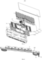
- FIGS. 1 to 6 illustrate an embodiment of the present application.
- the coil assembly 3 includes a installation bracket 302, a coil winding 301 and a magnet 2.
- the installation bracket 302 includes two opposite installation sides; the coil winding 301 is installed on one of the installation sides; the magnet 2 is provided on the other of the installation sides, and the magnet 2 is configured to be installed on the electromagnetic cooking appliance 100.
- the coil assembly 3 is configured to be installed in the electromagnetic cooking appliance 100; the electromagnetic cooking appliance 100 has multiple installation stations, and each installation station can be installed with one coil assembly 3.
- Each coil assembly 3 forms a heating unit located in the electromagnetic cooking appliance 100; the coil winding 301 is installed on one of the installation sides of the installation bracket 302, so that when the installation bracket 302 is installed on the corresponding installation station, it is set close to the panel 102 of the electromagnetic cooking appliance 100 to heat the pot on the panel 102.
- the magnet 2 Since the magnet 2 is provided on the other installation side of the installation bracket 302, when the installation bracket 302 is installed on the corresponding installation station, the magnet 2 is independently installed on the installation station, thereby exerting a magnetization effect on the corresponding coil winding 301 to improve the heating efficiency of the pot.
- the present application makes the magnet 2 and the installation bracket 302 independent with each other.
- the magnet 2 can be directly installed at the corresponding installation station, and the specific installation forms and installation positions are diversified.
- the installation method of the magnet 2 is simple, and there is no need for the installation bracket 302 to install the magnet 2 anymore, and the assembly structure of the coil assembly 3 is simple.
- the electromagnetic cooking appliance 100 to which the coil assembly 3 is applied is provided with a plurality of installation stations, and the coil assembly 3 is installed corresponding to each installation station. That is, a plurality of the coil assemblies 3 are densely distributed at the inside of the panel 102, so that the entire area of the panel 102 can be placed with pots and pans for heating; and the larger the size of the coil assembly 3, the greater the heating blind area between the two adjacent coil assemblies 3. This may affect the heating effect of the electromagnetic cooking appliance 100 on the pot.
- the outer diameter of the coil assembly 3 is less than or equal to 80 mm.
- the electromagnetic cooking appliance 100 includes a shell 1 and a plurality of coil assemblies 3.
- the shell 1 includes a installation base 101 and a panel 102 covering the installation base 101.
- the installation base 101 is provided with a plurality of installation stations. On each of the installation stations, the coil winding 301, the installation bracket 302, and the magnet 2 are stacked in sequence along the direction from the panel 102 to the installation base 101.
- the specific structure of the coil assembly 3 refers to the above-mentioned embodiments. Since the electromagnetic cooking appliance 100 adopts all the technical solutions of all the above-mentioned embodiments, it also has the beneficial effects brought by the technical solutions of the above-mentioned embodiments, which will not be discussed here.
- the coil assembly 3 includes the installation bracket 302 and the coil winding 301.
- the coil winding 301 is installed on the installation bracket 302, so that when the installation bracket 302 is installed on the corresponding installation station, it is arranged close to the panel 102 to heat the pot on the panel 102.
- the magnet 2 is installed independently and is provided on the side of the coil winding 301 close to the installation base 101, thereby exerting a magnetization effect on the corresponding coil winding 301 to improve the heating efficiency of the pot; compared with the related art, in which the coil winding and the magnet are combined and installed in the electromagnetic heating coil plate, and another fixed bracket needs to be installed between the coil winding and the magnet to separate the magnet and the coil winding, the present application makes the magnet 2 and the installation bracket 302 independent of each other.
- the magnet 2 can be directly installed on the corresponding installation station, and the specific installation forms and installation positions are diverse.
- the installation method of the magnet 2 is simple. There is no need to install the magnet 2 on the installation bracket 302.
- the assembly structure of the coil assembly 3 is simple.
- the electromagnetic cooking appliance 100 can be an induction cooker; in addition, when each installation bracket 302 is installed at the corresponding installation station, the coil winding 301, the installation bracket 302 and the magnet 2 are stacked in sequence. That is, correspondingly, the installation bracket 302 is located between the magnet 2 and the coil winding 301.
- the magnet 2 and the coil winding 301 are spaced apart to prevent the installation distance between the magnet 2 and the coil winding 301 from being too close, causing the coil winding 301 to be subjected to discharge breakdown with the influence of the magnet 2 when alternating current is passed through it during operation.
- the magnet 2 is independently installed on the installation station, in order to avoid that, after the magnet 2 is installed on the installation station, the position relationship between the magnet2 and the corresponding coil assembly 3 will be offset during the use of the electromagnetic cooking appliance 100 so as to affect the magnetization effect of the corresponding coil winding 301; specifically, at each installation station, the magnet 2 is clamped and fixed on the corresponding installation station.
- the magnet 2 By arranging the magnet 2 to be clamped and installed on the corresponding installation station, compared with the conventional method of fixing the magnet 2 by gluing in the related art, the magnet 2 is abutted and fixed rigidly on the installation station, which can limit the relative offset between the magnet 2 and the coil winding 301 in multiple directions; in addition, the magnet 2 can also be clamped at the installation station through adhesive way to bond with the contact plane to achieve better fixation.
- the installation base 101 is provided with a convex portion 4 to form the installation station;
- the magnet 2 is provided with a first through hole 5, and the first through hole 5 is configured for the convex portion 4 to insert and clamp in place.
- the installation base 101 is provided with a groove 13 to form the installation station; correspondingly, the groove 13 is configured for the magnet 2 to be clamped and embedded.
- the groove 13 is configured for the corresponding magnet 2 to be embedded, and the groove wall part abuts the outer periphery of the magnet 2, so that the circumferential side of the magnet 2 is restricted to achieve the effect of limiting the position of the magnet 2.
- the magnet 2 and the coil assembly 3 are installed at an installation station; at least part of the projection of the coil winding 301 located at the coil assembly 3, in the direction from the panel 102 to the installation base 101, can fall on the corresponding magnet 2 installed on the same installation station.
- the magnet 2 has a magnetization effect on the corresponding coil winding 301, making the magnetic flux lines of the coil winding 301 more concentrated, further improving the heating efficiency, and reducing the electromagnetic field radiated to the installation base 101.
- the side of the installation bracket 302 close to the magnet 2 is installed with a fastener 6, and the installation base 101 is provided with a buckle portion 7.
- the fastener 6 passes through the first through hole 5 of the magnet 2 and is fastened on the buckle portion 7.
- the fixed installation of the coil assembly 3 is achieved by arranging the fastener 6 to be fastened and installed on the installation base 101; since the magnet 2 is sandwiched between the installation bracket 302 and the installation base 101, in order to facilitate that when the installation bracket 302 is installed on the installation station, its fastener 6 can pass through the magnet 2 and be fastened on the installation station, thus, the fastener 6 is provided to directly pass through the first through hole 5 on the magnet 2.
- the first through hole 5 can also be configured for the fastener 6 to insert through to improve its functional diversification and improve the compactness of the installation of the overall device; and the form of the buckle portion 7 provided on the installation station is not limited; a buckle groove may be provided at the position corresponding to the fastener 6 for the fastener 6 to pass through and fasten; or a buckle portion may be provided, when the fastener 6 is fastened to the buckle portion 7, the buckling end of the fastener 6 is correspondingly buckled on the outer periphery of the buckle portion.
- the number of the fasteners 6 is not limited and can be one or more. If the fastener 6 is one, the fastener 6 can be installed in the middle of the installation bracket 302, so that when installing the installation bracket 302, its stability is improved; if there are multiple fasteners 6, multiple fasteners 6 can be arranged surrounding the installation bracket 302, so that when installing the installation bracket 302, its stability is improved; in this embodiment, one fastener 6 is provided and is located in the middle of the installation bracket 302. Compared with the solution in which multiple fasteners 6 are provided, there is only one attachment point between the installation bracket 302 and the installation base 101, which makes disassembly more convenient while ensuring that the installation bracket 302 and the installation base 101 are firmly fixed.
- the installation base 101 is provided with a buckle groove 7a, and the buckle groove 7a forms the corresponding buckle portion 7.
- the fastener 6 on the installation bracket 302 can be directly buckled into the corresponding buckle groove 7a. That is, the coil assembly 3 and the installation bar 10b are installed in a rigid snap connection manner to improve the reliability of the connection between the two.
- the buckle groove 7a is configured as an elongated groove; correspondingly, the fastener 6 is configured as an elongated shape.
- the installation base 101 is provided with a first rib 4a on the side close to the magnet 2 and around the periphery of the buckle groove 7a to form the convex portion 4.
- the first rib 4a protrudes from the buckle groove 7a in the direction from the installation base 101 to the panel 102, so that it can be embedded into the first through hole 5 of the magnet 2 when the magnet 2 is installed on the installation base 101; and the surrounding first ribs 4a will not block the opening of the buckle groove 7a, so that the fastener 6 can be smoothly embedded into the buckle groove 7a.
- the coil winding 301 is a multi-turn coil wound sequentially from the inside to the outside, it has an inner lead on the inside and an outer lead on the outside.
- the installation bracket 302 is provided with a second through hole 8, and the fastener 6 is hollow; the second through hole 8 is connected with the cavity of the fastener 6 to form a wire passage.
- the second through hole 8 opened through the installation bracket 302 corresponds to the inner position of the coil winding 301, that is, the inner lead of the coil winding 301 can be introduced into the wire passage from the open position of one end of the second through hole 8, and passes through the cavity of the fastener 6 to the outside of the installation bracket 302 through the wire passage, thereby facilitating the wiring installation of the coil winding 301.
- the installation bracket 302 is provided with a second rib 9 on an installation side where the coil winding 301 is installed and on the periphery of the second through hole 8.
- the second rib 9 is arranged in a semi-encircling manner to form a wire groove 10 communicating with the second through hole 8. Since the second through hole 8 is provided inside the coil winding 301, correspondingly, the second rib 9 is also provided inside the coil winding 301.
- the second rib 9 is in the form of semi-encircling arrangement to form a wire passage 10.
- the inner lead of the coil winding 301 can be introduced from the wire passage 10 into the wire passage, and the wire passage 10 limits the inner lead of the coil winding 301.
- the installation bracket 302 is provided with an installation slot on one of the installation sides where the coil winding 301 is installed, and the coil winding 301 is correspondingly installed in the installation slot, so that the coil winding 301 can be protected.
- the coil assembly 3 also includes a heat insulation plate 303.
- the heat insulation plate 303 is installed on a side of the coil winding 301 away from the installation bracket 302 to prevent the heat on the panel 102 from diffusing to the coil winding 301 when the pot is placed on the panel 102 for heating; the heat insulation plate 303 and the coil winding 301 can interact with each other for bonding in one piece when not installed on the installation bracket 302 to facilitate assembly to the installation bracket 302, and the arrangement form of the heat insulation plate 303 is not limited.
- the heat insulation plate 303 is configured as a mica sheet.
- the coil assembly 3 also includes a temperature measuring member 304, which can be installed on the heat insulation plate 303 or on the installation bracket 302.
- the temperature measuring member 304 is provided to protrude from the the coil winding 301.
- the temperature measuring member 304 can measure the temperature of the overlapping area of the panel 102 and the corresponding coil assembly 3 to monitor the temperature of the panel 102 and the pot in real time during cooking; specifically, in this embodiment, the temperature measuring member 304 is installed on the installation bracket 302 and close to its middle position; correspondingly, a third through hole 14 can be provided in the middle position of the heat insulation plate 303, and the third through hole 14 is connected to the wire passage.
- the temperature measuring member 304 is installed on the installation bracket 302, its lead wire can extend from the third through hole 14 into the wire passage and extend out of the installation bracket 302, so as to facilitate the wiring connection of the leads of the temperature measuring member
- the installation base 101 includes a base 10a and a plurality of installation bars 10b.
- the plurality of installation bars 10b are spaced apart in the base 10a.
- Each installation bar 10b is provided with a plurality of the buckle grooves 7a.
- each installation bar 10b is provided with a plurality of installation stations for installing the magnet 2 and the coil assembly 3.
- Each coil assembly 3 and the installation bar 10b can be independently disassembled and assembled, and each of the installation bars 10b and the base 10a can also be independently disassembled and assembled, thereby facilitating the installation, disassembly and maintenance of the components in the electromagnetic cooking appliance 100.
- the base 10a forms the outer shell frame of the electromagnetic cooking appliance 100.
- the base 10a is semi-encircling to form an installation cavity with an open end.
- the base 10a includes an installation bottom plate 101a and a shell base 102a.
- the shell base 102a mainly functions to enclose and form an installation cavity and protect the components of the electromagnetic cooking appliance 100.
- the installation bottom plate 101a is placed at the bottom of the shell base 102a and is mainly configured for the internal parts of the electromagnetic cooking appliance 100 to be installed. That is, in this embodiment, the installation bottom plate 101a is configured for mounting a plurality of the installation bars 10b; the electromagnetic cooking appliance 100 also includes a cooling fan 15, a circuit integrated motherboard 16 and a display control panel 17.
- the cooling fan 15, the circuit integrated motherboard 16 and the display control panel 17 are all installed on the installation bottom plate 101a, and are located in the installation space formed by the plurality of the installation bars 10b and the installation bottom plate 101a in an interval manner.
- a plurality of the coil assemblies 3 and the corresponding magnets 2 being directly installed on the installation bottom plate 101a
- when a plurality of the installation bars 10b are installed inside the installation base 101 it is spaced from the installation base 101 along the direction from the installation base 101 to the panel 102, and the installation space formed by being spaced apart from the installation bottom plate 101a is larger, thereby making it easier to install components such as the cooling fan 15 in the base 10a.
- the installation bar 10b is arranged in a long shape, so that the two ends of the installation bar 10b can be closer to the two opposite side walls of the base 10a on the side wall; a plurality of the installation bars 10b are arranged at intervals to fully utilize the installation cavity area of the base 10a.
- the magnet 2 is clamped on the installation bar 10b through the convex portion 4, and the convex portion 4 can be provided on the side of the installation bar 10b close to the panel 102 or the side close to the installation bottom plate 101a.
- the magnet 2 is installed on the side of the installation bar 10b close to the panel 102, so that the separation of the magnet 2 is further restricted when the installation bracket 302 is inserted into the buckle groove 7a through the fastener 6.
- each installation bar 10b in order to improve the heating efficiency of the coil winding 301 for the pot placed on the panel 102, each installation bar 10b can be movable along the direction from the base 10a to the panel 102, and at least one elastic resisting member 11 is installed between installation bar 10b and the bases 10a. Among them, at least one elastic resisting member 11 is provided between each installation bar 10b and the base 10a. The elastic resisting member 11 elastically expands and contracts along the direction from the panel 102 to the base 10a, and can resist the corresponding installation bar 10b approaching the panel 102, so that the plurality of coil assemblies 3 located on the installation bar 10b are simultaneously abutted against the inside of the panel 102 to achieve better cooking and heating effect.
- the electromagnetic heating coil plate used in the related art which needs to be independently installed with elastic elements to abut against the corresponding inside of the cooking panel 102
- this embodiment only a plurality of the coil assemblies 3 need to be fixedly installed on the installation bar 10b, and the elastic resisting member 11 is installed between the installation bar 10b and the base 10a, which reduces the required number of the elastic resisting members 11 when installing multiple coil assemblies 3, and the installation operation is simpler;
- the form of the elastic resisting member 11 is not limited, and can be a straight spring, a tower spring, etc.
- each installation bar 10b is elongated, correspondingly, the number of elastic resisting members 11 is at least two, and they are spaced apart along the length direction of the corresponding installation bar 10b.
- two elastic resisting members 11 are installed corresponding to the lower end of the installation bar 10b and spaced along its length direction.
- the two elastic resisting members 11 are symmetrically arranged along the center line in the length direction thereof to balance the force of both ends of the installation bar 10b.
- the two elastic resisting members are respectively close to both ends of the installation bars 10b in the length direction.
- the reserved space between the two elastic resisting members 11 is larger, thereby facilitating the arrangement and installation of the cooling fan 15 and other components.
- the installation bar 10b can be movable along the direction from the base 10a to the panel 102, in order to avoid displacement in other directions during its movable stroke, at least one sliding portion 12 is provided on one side of each installation bar 10b close to the bottom plate; the base 10a is provided with at least one chute corresponding to the sliding portion 12, and the sliding portion 12 is movably installed in the corresponding chute to guide the corresponding installation bar 10b to move.
- the sliding portion 12 embedded in the chute the sliding portion 12 and the chute both extend and open in the direction from the base 10a to the panel 102.
- the chute restricts the sliding direction of the sliding portion 12, so that the sliding portion 12 can only move along the direction from the bottom to the mouth of the chute, and the movement direction of the installation bar 10b provided with the sliding portion 12 correspondingly is limited; there is no limit to the number of the sliding portions 12 installed on the side of each installation bar 10b close to the base 10a.
- two of the limiting portions are installed at intervals along the width direction of the installation bar 10b and are provided close to the end of the installation bar 10b. Without affecting the installation of other components between installation bar 10b and the base 10a, the relative rotation between the installation bar 10b and the base 10a can also be restricted to improve the stability of its installation.
- the installation base 101 includes a base 10a and a plurality of installation bars 10b, and the plurality of the installation bars 10b are arranged at intervals in the base 10a.
- Each installation bar 10b is provided with a plurality of grooves 13 on one side close to the base 10a.
- multiple installation bars 10b are provided at intervals on the base 10a, and the magnet 2 and the coil assembly 3 can be independently installed on the installation bars 10b, so as to facilitate installation, disassembly and maintenance of components in the electromagnetic heating unit; in addition, since the coil assembly 3 is installed on the side of the installation bar 10b close to the panel 102, and the magnet 2 is installed on one side of the installation bar 10b close to the base 10a, so on the premise of ensuring that the magnet 2 exerts a magnetization effect on the coil winding 301, the disassembly and installation of the two do not interfere with each other, so as to facilitate disassembly and assembly.
- the coil assembly 3 described in this embodiment has the same structure as the coil assembly 3 in the solution in which the convex portion 4 is provided on the installation station to engage the magnet 2 as described above.
- the structure of the installation bar 10b is also the same as the structure of the installation bar 10b described in the above embodiment.
- the elastic resisting member 11 can be provided between the installation bracket 302 and the installation bar 10b, or between the installation bar 10b and the base 10a.
- the elastic resisting member 11 is provided between the installation bracket 302 and the installation bar 10b, correspondingly, the installation bar 10b can be fixedly installed on the base 10a.
- the magnet 2 can also be provided as the installation bar 10b.
- the buckle groove 7a is provided corresponding to each of the installation stations on the magnet 2 for installation of the coil assembly 3.
Landscapes
- Physics & Mathematics (AREA)
- Electromagnetism (AREA)
- Engineering & Computer Science (AREA)
- Chemical & Material Sciences (AREA)
- Combustion & Propulsion (AREA)
- Mechanical Engineering (AREA)
- General Engineering & Computer Science (AREA)
- Induction Heating Cooking Devices (AREA)
- General Induction Heating (AREA)
- Electric Stoves And Ranges (AREA)
Abstract
includes two installation sides arranged opposite to each other. The coil winding is installed on
5 one of the installation sides. The magnet is arranged on the other of the installation sides, and
the magnet is configured to be installed on the electromagnetic cooking appliance.
Description
- The present application claims priority to
Chinese Patent Applications No. 202210660523.3, filed on June 10, 2022 - The present application relates to the technical field of cooking appliances, in particular to a coil assembly and an electromagnetic cooking appliance.
- In home appliances, electromagnetic heating methods are almost universally popular. Especially for multi-head stoves, induction cookers, etc. that use electromagnetic heating, the electromagnetic heating position is almost always fixed to one or several positions. There are no heating coils in the rest of the heating panel, and can only perform local heating, and it needs to be aligned with the heating position when used. If the position is off, it will affect the cooking effect. Therefore, multiple heating points need to be set up for full-area heating. However, the magnets and coil winding in the traditional electromagnetic heating coil plate need to be installed in combination. The structure is complex and is not suitable for induction cookers installed in full-area heating.
- The main purpose of the present application is to propose a coil assembly and an electromagnetic cooking appliance, aiming to provide an electromagnetic heating coil plate structure suitable for installation in a full-area heating induction cooker.
- In order to achieve the above purpose, the present application proposes a coil assembly, comprising:
- an installation bracket comprising two installation sides arranged oppositely;
- a coil winding installed on one of the installation sides; and
- a magnet provided on the other of the installation sides and being installed on an electromagnetic cooking appliance.
- The present application also proposes an electromagnetic cooking appliance, comprising:
- a shell comprising an installation base and a panel covering the installation base; a plurality of installation stations are provided on the installation base; and
- a plurality of coil assemblies installed corresponding to the plurality of installation stations; the coil assemblies comprise the coil assembly;
- At each of the installation stations, the coil winding, the installation bracket, and the magnet are stacked in sequence along a direction from the panel to the installation base.
- In an embodiment, at each of the installation stations, the magnet is clamped and fixed at a corresponding installation station.
- In an embodiment, the installation base is provided with a convex portion to form the installation station; and
- the magnet is provided with a first through hole, and the convex portion passes through the first through hole and clamps.
- In an embodiment, the installation bracket is further equipped with a fastener on the installation side where the magnet is installed; the installation base is provided with a buckle portion, and the fastener passes through the first through hole of the magnet and is buckled on the buckle portion.
- In an embodiment, the installation base is provided with a buckle groove, and the buckle groove forms a corresponding buckle portion.
- In an embodiment, the buckle groove is an elongated groove; and
the fastener is arranged in a long shape. - In an embodiment, the installation base is provided with a first rib on a side close to the magnet and around a periphery of the buckle groove to form the convex portion.
- In an embodiment, the installation bracket is provided with a second through hole, and the fastener is hollow; and
the second through hole is communicated with a cavity of the fastener to form a wire passage. - In an embodiment, the installation bracket is provided with a second rib on one of the installation sides where the coil winding is installed and on a periphery of the second through hole, and the second rib is arranged in a semi-encircling manner to form a wire groove communicating with the second through hole.
- In an embodiment, the installation base comprises:
- a base; and
- a plurality of installation bars arranged at intervals in the base; each of installation bars is provided with a plurality of buckle grooves.
- In an embodiment, each of the installation bars is movable along a direction from the base to the panel, and at least one elastic resisting member is installed between the installation bar and the base.
- In an embodiment, each of the installation bars is provided with at least one sliding portion on a side close to the base; and
- the base is provided with at least one chute corresponding to the sliding portion, and the sliding portion is movably provided in a corresponding chute to guide a movement of a corresponding installation bar.
- In an embodiment, a groove is provided on the installation base to form the installation station; and
the magnet is clamped and embedded through the groove. - In an embodiment, the installation base comprises:
- base; and
- a plurality of installation bars arranged at intervals in the base; each of the installation bars is provided with a plurality of grooves on a side close to the base.
- In the technical solution of the present application, the coil assembly is configured to be installed in an electromagnetic cooking appliance. The electromagnetic cooking appliance has multiple installation stations, and each installation station can be installed with one of the coil assemblies. Each coil assembly forms a heating unit located in the electromagnetic cooking appliance; the coil winding is installed on one of the installation sides of the installation bracket to be provided close to the panel of the electromagnetic cooking appliance when the installation bracket is installed on the corresponding installation station, so as to heat the pot located on the panel. Since the magnet is provided on the other installation side of the installation bracket, when the installation bracket is installed at the corresponding installation station, the magnet is independently installed at the installation station, thereby exerting a magnetization effect on the corresponding coil winding to improve the heating efficiency of the pot; compared with the related art in which the coil winding and the magnet are combined and installed in the electromagnetic heating coil plate, and another fixed bracket needs to be installed between the coil winding and the magnet to separate the magnet and the coil winding, the present application makes the magnet and the installation bracket independent of each other, and the magnet can be installed directly at the corresponding installation station. The specific installation forms and installation positions are diverse, and the magnet installation method is simple; there is no need to install the magnet on the installation bracket, and the assembly structure of the coil assembly is simple.
- In order to more clearly illustrate the technical solutions in the embodiments of the present application or the related art, the following will briefly introduce the drawings that need to be used in the description of the embodiments or the related art. Obviously, the accompanying drawings in the following description are only some embodiments of the present application, and those skilled in the art can also obtain other drawings according to the structures shown in these drawings without creative effort.
-
FIG. 1 is a three-dimensional exploded schematic diagram of an electromagnetic cooking appliance according to an embodiment of the present application. -
FIG. 2 is a schematic diagram of an assembly structure of a coil assembly and an installation bar inFIG. 1 . -
FIG. 3 is a three-dimensional exploded structural diagram of the assembly of the coil assembly and the installation bar inFIG. 2 . -
FIG. 4 is a schematic diagram of the exploded structure of the coil assembly inFIG. 2 . -
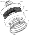
FIG. 5 is a schematic diagram of the assembly structure of the coil assembly and the installation bar inFIG. 1 according to another embodiment. -
FIG. 6 is a schematic diagram of the exploded structure of the coil assembly inFIG. 5 . -
reference sign name reference sign name 100 electromagnetic cooking appliance 4a first rib 1 shell 5 first through hole 101 installation base 6 fastener 10a base 7 buckle portion 101a installation bottom plate 7a buckle groove 102a shell base 8 second through hole 10b installation bar 9 second rib 102 panel 10 wire groove 2 magnet 11 elastic resisting member 3 coil assembly 12 sliding portion 301 coil winding 13 groove 302 installation bracket 14 third through hole 303 heat insulation plate 15 cooling fan 304 temperature measuring member 16 circuit integrated main board 4 convex portion 17 display control panel - The realization, functional features and advantages of the present application will be further described in conjunction with the embodiments and with reference to the accompanying drawings.
- The following will clearly and completely describe the technical solutions in the embodiments of the present application with reference to the accompanying drawings in the embodiments of the present application. Obviously, the described embodiments are only part of the embodiments of the present application, not all of them. Based on the embodiments in the present application, all other embodiments obtained by those skilled in the art without creative efforts fall within the protection scope of the present application.
- It should be noted that if there is a directional indication (such as up, down, left, right, front, back...) in the embodiment of the present application, the directional indication is only configured to explain the relationship between the components in a certain posture. If the specific posture changes, the directional indication will also change accordingly.
- In addition, if there are descriptions involving "first", "second", etc. in the embodiments of the present application, the descriptions of "first", "second", etc. are only for descriptive purposes, and cannot be understood as indicating or implying their relative importance or implicitly indicating the number of indicated technical features. Thus, the features defined as "first" and "second" may explicitly or implicitly include at least one of these features. In addition, if "and/or" appears throughout the text, its meaning includes three parallel plans, taking "A and/or B" as an example, including plan A, or plan B, or A and B is a solution that is satisfied at the same time. In addition, the technical solutions of the various embodiments can be combined with each other, but it must be based on the realization of those skilled in the art. When the combination of technical solutions is contradictory or cannot be realized, it should be considered that the combination of technical solutions does not exist, nor within the protection scope required by the present application.
- In home appliances, electromagnetic heating methods are almost universally popular. Especially for multi-head stoves, induction cookers, etc. that use electromagnetic heating, the electromagnetic heating position is almost always fixed to one or several positions. There are no heating coils in the rest of the heating panel, and can only perform local heating, and it needs to be aligned with the heating position when used. If the position is off, it will affect the cooking effect. Therefore, multiple heating points need to be set up for full-area heating. However, the magnet and coil winding in the traditional electromagnetic heating coil plate need to be installed in combination. The structure is complex and is not suitable for induction cookers installed in full-area heating.
- In view of this, the present application proposes a coil assembly, and
FIGS. 1 to 6 illustrate an embodiment of the present application. - Referring to
FIGS. 1 to 3 , thecoil assembly 3 includes ainstallation bracket 302, a coil winding 301 and amagnet 2. Theinstallation bracket 302 includes two opposite installation sides; the coil winding 301 is installed on one of the installation sides; themagnet 2 is provided on the other of the installation sides, and themagnet 2 is configured to be installed on theelectromagnetic cooking appliance 100. - In the technical solution of the present application, the
coil assembly 3 is configured to be installed in theelectromagnetic cooking appliance 100; theelectromagnetic cooking appliance 100 has multiple installation stations, and each installation station can be installed with onecoil assembly 3. Eachcoil assembly 3 forms a heating unit located in theelectromagnetic cooking appliance 100; the coil winding 301 is installed on one of the installation sides of theinstallation bracket 302, so that when theinstallation bracket 302 is installed on the corresponding installation station, it is set close to thepanel 102 of theelectromagnetic cooking appliance 100 to heat the pot on thepanel 102. Since themagnet 2 is provided on the other installation side of theinstallation bracket 302, when theinstallation bracket 302 is installed on the corresponding installation station, themagnet 2 is independently installed on the installation station, thereby exerting a magnetization effect on the corresponding coil winding 301 to improve the heating efficiency of the pot. Compared with the related art, which combines coil winding and magnets in an electromagnetic heating coil plate and requires an additional fixed bracket between the coil winding and magnets to separate the magnets and coil winding, the present application makes themagnet 2 and theinstallation bracket 302 independent with each other. Themagnet 2 can be directly installed at the corresponding installation station, and the specific installation forms and installation positions are diversified. The installation method of themagnet 2 is simple, and there is no need for theinstallation bracket 302 to install themagnet 2 anymore, and the assembly structure of thecoil assembly 3 is simple. - Furthermore, since the
electromagnetic cooking appliance 100 to which thecoil assembly 3 is applied is provided with a plurality of installation stations, and thecoil assembly 3 is installed corresponding to each installation station. That is, a plurality of thecoil assemblies 3 are densely distributed at the inside of thepanel 102, so that the entire area of thepanel 102 can be placed with pots and pans for heating; and the larger the size of thecoil assembly 3, the greater the heating blind area between the twoadjacent coil assemblies 3. This may affect the heating effect of theelectromagnetic cooking appliance 100 on the pot. In an embodiment, the outer diameter of thecoil assembly 3 is less than or equal to 80 mm. - Please referring to
FIGS 1 to 3 again, the present application also proposes anelectromagnetic cooking appliance 100. Theelectromagnetic cooking appliance 100 includes ashell 1 and a plurality ofcoil assemblies 3. Theshell 1 includes ainstallation base 101 and apanel 102 covering theinstallation base 101. Theinstallation base 101 is provided with a plurality of installation stations. On each of the installation stations, the coil winding 301, theinstallation bracket 302, and themagnet 2 are stacked in sequence along the direction from thepanel 102 to theinstallation base 101. The specific structure of thecoil assembly 3 refers to the above-mentioned embodiments. Since theelectromagnetic cooking appliance 100 adopts all the technical solutions of all the above-mentioned embodiments, it also has the beneficial effects brought by the technical solutions of the above-mentioned embodiments, which will not be discussed here. - That is, a plurality of installation stations are provided on the
installation base 101, and thecoil assembly 3 is installed corresponding to each installation station to form a heating unit located in theelectromagnetic cooking appliance 100. Thecoil assembly 3 includes theinstallation bracket 302 and the coil winding 301. The coil winding 301 is installed on theinstallation bracket 302, so that when theinstallation bracket 302 is installed on the corresponding installation station, it is arranged close to thepanel 102 to heat the pot on thepanel 102. At each installation station, themagnet 2 is installed independently and is provided on the side of the coil winding 301 close to theinstallation base 101, thereby exerting a magnetization effect on the corresponding coil winding 301 to improve the heating efficiency of the pot; compared with the related art, in which the coil winding and the magnet are combined and installed in the electromagnetic heating coil plate, and another fixed bracket needs to be installed between the coil winding and the magnet to separate the magnet and the coil winding, the present application makes themagnet 2 and theinstallation bracket 302 independent of each other. Themagnet 2 can be directly installed on the corresponding installation station, and the specific installation forms and installation positions are diverse. The installation method of themagnet 2 is simple. There is no need to install themagnet 2 on theinstallation bracket 302. The assembly structure of thecoil assembly 3 is simple. - The specific type of the
electromagnetic cooking appliance 100 is not limited. In this embodiment, theelectromagnetic cooking appliance 100 can be an induction cooker; in addition, when eachinstallation bracket 302 is installed at the corresponding installation station, the coil winding 301, theinstallation bracket 302 and themagnet 2 are stacked in sequence. That is, correspondingly, theinstallation bracket 302 is located between themagnet 2 and the coil winding 301. Themagnet 2 and the coil winding 301 are spaced apart to prevent the installation distance between themagnet 2 and the coil winding 301 from being too close, causing the coil winding 301 to be subjected to discharge breakdown with the influence of themagnet 2 when alternating current is passed through it during operation. - Furthermore, since the
magnet 2 is independently installed on the installation station, in order to avoid that, after themagnet 2 is installed on the installation station, the position relationship between the magnet2 and the correspondingcoil assembly 3 will be offset during the use of theelectromagnetic cooking appliance 100 so as to affect the magnetization effect of the corresponding coil winding 301; specifically, at each installation station, themagnet 2 is clamped and fixed on the corresponding installation station. By arranging themagnet 2 to be clamped and installed on the corresponding installation station, compared with the conventional method of fixing themagnet 2 by gluing in the related art, themagnet 2 is abutted and fixed rigidly on the installation station, which can limit the relative offset between themagnet 2 and the coil winding 301 in multiple directions; in addition, themagnet 2 can also be clamped at the installation station through adhesive way to bond with the contact plane to achieve better fixation. - In an embodiment, the
installation base 101 is provided with aconvex portion 4 to form the installation station; themagnet 2 is provided with a first through hole 5, and the first through hole 5 is configured for theconvex portion 4 to insert and clamp in place. By providing theconvex portion 4 at each installation station, when theconvex portion 4 is embedded in the corresponding first through hole 5, its outer peripheral portion is abutted against the hole wall of the first through hole 5 in order to limit and fix themagnet 2. - In another embodiment, the
installation base 101 is provided with agroove 13 to form the installation station; correspondingly, thegroove 13 is configured for themagnet 2 to be clamped and embedded. By providing agroove 13 on each installation station, thegroove 13 is configured for thecorresponding magnet 2 to be embedded, and the groove wall part abuts the outer periphery of themagnet 2, so that the circumferential side of themagnet 2 is restricted to achieve the effect of limiting the position of themagnet 2. - It should be noted that, as in the two embodiments described above, whether the
convex portion 4 or thegroove 13 is provided on the installation station to limit and fix themagnet 2, there is no restriction on the arrangement form and quantity of themagnet 2. For example, themagnet 2 and thecoil assembly 3 are installed at an installation station; at least part of the projection of the coil winding 301 located at thecoil assembly 3, in the direction from thepanel 102 to theinstallation base 101, can fall on thecorresponding magnet 2 installed on the same installation station. Themagnet 2 has a magnetization effect on the corresponding coil winding 301, making the magnetic flux lines of the coil winding 301 more concentrated, further improving the heating efficiency, and reducing the electromagnetic field radiated to theinstallation base 101. - Please referring to
FIGS. 3 and 4 , in the above embodiment, on the basis of the first through hole 5 being opened on themagnet 2, further, the side of theinstallation bracket 302 close to themagnet 2 is installed with afastener 6, and theinstallation base 101 is provided with abuckle portion 7. Thefastener 6 passes through the first through hole 5 of themagnet 2 and is fastened on thebuckle portion 7. The fixed installation of thecoil assembly 3 is achieved by arranging thefastener 6 to be fastened and installed on theinstallation base 101; since themagnet 2 is sandwiched between theinstallation bracket 302 and theinstallation base 101, in order to facilitate that when theinstallation bracket 302 is installed on the installation station, itsfastener 6 can pass through themagnet 2 and be fastened on the installation station, thus, thefastener 6 is provided to directly pass through the first through hole 5 on themagnet 2. On the premise of allowing the correspondingconvex portion 4 to be embedded, the first through hole 5 can also be configured for thefastener 6 to insert through to improve its functional diversification and improve the compactness of the installation of the overall device; and the form of thebuckle portion 7 provided on the installation station is not limited; a buckle groove may be provided at the position corresponding to thefastener 6 for thefastener 6 to pass through and fasten; or a buckle portion may be provided, when thefastener 6 is fastened to thebuckle portion 7, the buckling end of thefastener 6 is correspondingly buckled on the outer periphery of the buckle portion. - The number of the
fasteners 6 is not limited and can be one or more. If thefastener 6 is one, thefastener 6 can be installed in the middle of theinstallation bracket 302, so that when installing theinstallation bracket 302, its stability is improved; if there aremultiple fasteners 6,multiple fasteners 6 can be arranged surrounding theinstallation bracket 302, so that when installing theinstallation bracket 302, its stability is improved; in this embodiment, onefastener 6 is provided and is located in the middle of theinstallation bracket 302. Compared with the solution in whichmultiple fasteners 6 are provided, there is only one attachment point between theinstallation bracket 302 and theinstallation base 101, which makes disassembly more convenient while ensuring that theinstallation bracket 302 and theinstallation base 101 are firmly fixed. - In this embodiment, the
installation base 101 is provided with abuckle groove 7a, and thebuckle groove 7a forms thecorresponding buckle portion 7. When installing thecoil assembly 3 on the installation station, thefastener 6 on theinstallation bracket 302 can be directly buckled into thecorresponding buckle groove 7a. That is, thecoil assembly 3 and theinstallation bar 10b are installed in a rigid snap connection manner to improve the reliability of the connection between the two. - In an embodiment, the
buckle groove 7a is configured as an elongated groove; correspondingly, thefastener 6 is configured as an elongated shape. By arranging thebuckle groove 7a and thefastener 6 to be elongated, when thecoil assembly 3 is installed on the installation station, the rotation between thefastener 6 and thebuckle groove 7a is prevented, so as to prevent thecoil assembly 3 from rotating when installed on the installation station and improve the stability of its connection. - In an embodiment, since the first through hole 5 of the
magnet 2 needs to be clamped by theconvex portion 4 and can be penetrated by thefastener 6, in order to prevent the insertion of thefastener 6 from being affected when theconvex portion 4 is clamped in the first through hole 5, specifically, theinstallation base 101 is provided with afirst rib 4a on the side close to themagnet 2 and around the periphery of thebuckle groove 7a to form theconvex portion 4. By providing thefirst rib 4a around the periphery of thebuckle groove 7a, thefirst rib 4a protrudes from thebuckle groove 7a in the direction from theinstallation base 101 to thepanel 102, so that it can be embedded into the first through hole 5 of themagnet 2 when themagnet 2 is installed on theinstallation base 101; and the surroundingfirst ribs 4a will not block the opening of thebuckle groove 7a, so that thefastener 6 can be smoothly embedded into thebuckle groove 7a. - In addition, since the coil winding 301 is a multi-turn coil wound sequentially from the inside to the outside, it has an inner lead on the inside and an outer lead on the outside. When the coil winding 301 is installed on the
installation bracket 302, it is difficult for the inner leads located inside theinstallation bracket 302 to be routed out of theinstallation bracket 302 and connected to the circuit integratedmain board 16. Therefore, theinstallation bracket 302 is provided with a second throughhole 8, and thefastener 6 is hollow; the second throughhole 8 is connected with the cavity of thefastener 6 to form a wire passage. The second throughhole 8 opened through theinstallation bracket 302 corresponds to the inner position of the coil winding 301, that is, the inner lead of the coil winding 301 can be introduced into the wire passage from the open position of one end of the second throughhole 8, and passes through the cavity of thefastener 6 to the outside of theinstallation bracket 302 through the wire passage, thereby facilitating the wiring installation of the coil winding 301. - In an embodiment, the
installation bracket 302 is provided with a second rib 9 on an installation side where the coil winding 301 is installed and on the periphery of the second throughhole 8. The second rib 9 is arranged in a semi-encircling manner to form awire groove 10 communicating with the second throughhole 8. Since the second throughhole 8 is provided inside the coil winding 301, correspondingly, the second rib 9 is also provided inside the coil winding 301. The second rib 9 is in the form of semi-encircling arrangement to form awire passage 10. The inner lead of the coil winding 301 can be introduced from thewire passage 10 into the wire passage, and thewire passage 10 limits the inner lead of the coil winding 301. - In an embodiment, the
installation bracket 302 is provided with an installation slot on one of the installation sides where the coil winding 301 is installed, and the coil winding 301 is correspondingly installed in the installation slot, so that the coil winding 301 can be protected. - In addition, the
coil assembly 3 also includes aheat insulation plate 303. Theheat insulation plate 303 is installed on a side of the coil winding 301 away from theinstallation bracket 302 to prevent the heat on thepanel 102 from diffusing to the coil winding 301 when the pot is placed on thepanel 102 for heating; theheat insulation plate 303 and the coil winding 301 can interact with each other for bonding in one piece when not installed on theinstallation bracket 302 to facilitate assembly to theinstallation bracket 302, and the arrangement form of theheat insulation plate 303 is not limited. In this embodiment, theheat insulation plate 303 is configured as a mica sheet. - In an embodiment, the
coil assembly 3 also includes atemperature measuring member 304, which can be installed on theheat insulation plate 303 or on theinstallation bracket 302. Thetemperature measuring member 304 is provided to protrude from the the coil winding 301. When the correspondingcoil assembly 3 is installed in theelectromagnetic cooking appliance 100 and thetemperature measuring member 304 is close to the inside of thepanel 102, thetemperature measuring member 304 can measure the temperature of the overlapping area of thepanel 102 and the correspondingcoil assembly 3 to monitor the temperature of thepanel 102 and the pot in real time during cooking; specifically, in this embodiment, thetemperature measuring member 304 is installed on theinstallation bracket 302 and close to its middle position; correspondingly, a third throughhole 14 can be provided in the middle position of theheat insulation plate 303, and the third throughhole 14 is connected to the wire passage. When thetemperature measuring member 304 is installed on theinstallation bracket 302, its lead wire can extend from the third throughhole 14 into the wire passage and extend out of theinstallation bracket 302, so as to facilitate the wiring connection of the leads of thetemperature measuring member 304. - Please referring to
FIG. 1 , theinstallation base 101 includes abase 10a and a plurality ofinstallation bars 10b. The plurality of installation bars 10b are spaced apart in thebase 10a. Eachinstallation bar 10b is provided with a plurality of thebuckle grooves 7a. By arranging a plurality of installation bars 10b and installing them in thebase 10a at intervals, and providing a plurality ofbuckle grooves 7a on eachinstallation bar 10b, correspondingly, eachinstallation bar 10b is provided with a plurality of installation stations for installing themagnet 2 and thecoil assembly 3. Eachcoil assembly 3 and theinstallation bar 10b can be independently disassembled and assembled, and each of the installation bars 10b and thebase 10a can also be independently disassembled and assembled, thereby facilitating the installation, disassembly and maintenance of the components in theelectromagnetic cooking appliance 100. - The
base 10a forms the outer shell frame of theelectromagnetic cooking appliance 100. Thebase 10a is semi-encircling to form an installation cavity with an open end. Thebase 10a includes aninstallation bottom plate 101a and ashell base 102a. Theshell base 102a mainly functions to enclose and form an installation cavity and protect the components of theelectromagnetic cooking appliance 100. Theinstallation bottom plate 101a is placed at the bottom of theshell base 102a and is mainly configured for the internal parts of theelectromagnetic cooking appliance 100 to be installed. That is, in this embodiment, theinstallation bottom plate 101a is configured for mounting a plurality of the installation bars 10b; theelectromagnetic cooking appliance 100 also includes a coolingfan 15, a circuit integratedmotherboard 16 and adisplay control panel 17. The coolingfan 15, the circuit integratedmotherboard 16 and thedisplay control panel 17 are all installed on theinstallation bottom plate 101a, and are located in the installation space formed by the plurality of the installation bars 10b and theinstallation bottom plate 101a in an interval manner. Compared with a plurality of thecoil assemblies 3 and thecorresponding magnets 2 being directly installed on theinstallation bottom plate 101a, when a plurality of the installation bars 10b are installed inside theinstallation base 101, it is spaced from theinstallation base 101 along the direction from theinstallation base 101 to thepanel 102, and the installation space formed by being spaced apart from theinstallation bottom plate 101a is larger, thereby making it easier to install components such as the coolingfan 15 in thebase 10a. - In addition, since most induction cooker frames are arranged in a rectangular form, thereby forming a rectangular installation cavity with an open top; the
installation bar 10b is arranged in a long shape, so that the two ends of theinstallation bar 10b can be closer to the two opposite side walls of thebase 10a on the side wall; a plurality of the installation bars 10b are arranged at intervals to fully utilize the installation cavity area of thebase 10a. - The
magnet 2 is clamped on theinstallation bar 10b through theconvex portion 4, and theconvex portion 4 can be provided on the side of theinstallation bar 10b close to thepanel 102 or the side close to theinstallation bottom plate 101a. In order to ensure the reliability of the installation of themagnet 2, themagnet 2 is installed on the side of theinstallation bar 10b close to thepanel 102, so that the separation of themagnet 2 is further restricted when theinstallation bracket 302 is inserted into thebuckle groove 7a through thefastener 6. - In an embodiment, in order to improve the heating efficiency of the coil winding 301 for the pot placed on the
panel 102, eachinstallation bar 10b can be movable along the direction from thebase 10a to thepanel 102, and at least one elastic resistingmember 11 is installed betweeninstallation bar 10b and thebases 10a. Among them, at least one elastic resistingmember 11 is provided between eachinstallation bar 10b and thebase 10a. The elastic resistingmember 11 elastically expands and contracts along the direction from thepanel 102 to thebase 10a, and can resist thecorresponding installation bar 10b approaching thepanel 102, so that the plurality ofcoil assemblies 3 located on theinstallation bar 10b are simultaneously abutted against the inside of thepanel 102 to achieve better cooking and heating effect. Compared with the electromagnetic heating coil plate used in the related art, which needs to be independently installed with elastic elements to abut against the corresponding inside of thecooking panel 102, in this embodiment, only a plurality of thecoil assemblies 3 need to be fixedly installed on theinstallation bar 10b, and the elastic resistingmember 11 is installed between theinstallation bar 10b and thebase 10a, which reduces the required number of the elastic resistingmembers 11 when installingmultiple coil assemblies 3, and the installation operation is simpler; the form of the elastic resistingmember 11 is not limited, and can be a straight spring, a tower spring, etc. - Since each
installation bar 10b is elongated, correspondingly, the number of elastic resistingmembers 11 is at least two, and they are spaced apart along the length direction of thecorresponding installation bar 10b. By setting theinstallation bar 10b to be elongated, two elastic resistingmembers 11 are installed corresponding to the lower end of theinstallation bar 10b and spaced along its length direction. By providing support for two ends of theinstallation bar 10b, a stable support effect can be achieved for theinstallation bar 10b; in an embodiment, the two elastic resistingmembers 11 are symmetrically arranged along the center line in the length direction thereof to balance the force of both ends of theinstallation bar 10b. - In an embodiment, since the installation space formed by the intervals between the plurality of installation bars 10b and the
base 10a requires the installation of components such as the coolingfan 15, specifically, in this embodiment, in eachinstallation bar 10b, the two elastic resisting members are respectively close to both ends of the installation bars 10b in the length direction. By making the distance between the two elastic resistingmembers 11 as far as possible on the side of theinstallation bar 10b close to thebase 10a, the reserved space between the two elastic resistingmembers 11 is larger, thereby facilitating the arrangement and installation of the coolingfan 15 and other components. - In an embodiment, since the
installation bar 10b can be movable along the direction from thebase 10a to thepanel 102, in order to avoid displacement in other directions during its movable stroke, at least one slidingportion 12 is provided on one side of eachinstallation bar 10b close to the bottom plate; thebase 10a is provided with at least one chute corresponding to the slidingportion 12, and the slidingportion 12 is movably installed in the corresponding chute to guide thecorresponding installation bar 10b to move. By providing the slidingportion 12 embedded in the chute, the slidingportion 12 and the chute both extend and open in the direction from thebase 10a to thepanel 102. When the elastic resisting member is abutted against theinstallation bar 10b close to thepanel 102, the chute restricts the sliding direction of the slidingportion 12, so that the slidingportion 12 can only move along the direction from the bottom to the mouth of the chute, and the movement direction of theinstallation bar 10b provided with the slidingportion 12 correspondingly is limited; there is no limit to the number of the slidingportions 12 installed on the side of eachinstallation bar 10b close to thebase 10a. In this embodiment, two of the limiting portions are installed at intervals along the width direction of theinstallation bar 10b and are provided close to the end of theinstallation bar 10b. Without affecting the installation of other components betweeninstallation bar 10b and thebase 10a, the relative rotation between theinstallation bar 10b and thebase 10a can also be restricted to improve the stability of its installation. - Please referring to
FIGS. 1 ,4 and5 . In another embodiment described above, based on the solution that themagnet 2 is embedded in thegroove 13 for position-limiting installation, theinstallation base 101 includes abase 10a and a plurality ofinstallation bars 10b, and the plurality of the installation bars 10b are arranged at intervals in thebase 10a. Eachinstallation bar 10b is provided with a plurality ofgrooves 13 on one side close to thebase 10a. That is, in this embodiment,multiple installation bars 10b are provided at intervals on thebase 10a, and themagnet 2 and thecoil assembly 3 can be independently installed on the installation bars 10b, so as to facilitate installation, disassembly and maintenance of components in the electromagnetic heating unit; in addition, since thecoil assembly 3 is installed on the side of theinstallation bar 10b close to thepanel 102, and themagnet 2 is installed on one side of theinstallation bar 10b close to thebase 10a, so on the premise of ensuring that themagnet 2 exerts a magnetization effect on the coil winding 301, the disassembly and installation of the two do not interfere with each other, so as to facilitate disassembly and assembly. - Among them, the
coil assembly 3 described in this embodiment has the same structure as thecoil assembly 3 in the solution in which theconvex portion 4 is provided on the installation station to engage themagnet 2 as described above. The structure of theinstallation bar 10b is also the same as the structure of theinstallation bar 10b described in the above embodiment. When the elastic resistingmember 11 is provided on theinstallation bar 10b to abut thecoil assembly 3 to be close to thepanel 102, the elastic resistingmember 11 can be provided between theinstallation bracket 302 and theinstallation bar 10b, or between theinstallation bar 10b and thebase 10a. In this embodiment, the elastic resistingmember 11 is provided between theinstallation bracket 302 and theinstallation bar 10b, correspondingly, theinstallation bar 10b can be fixedly installed on thebase 10a. - It can be understood that when the elastic resisting
member 11 is provided between theinstallation bracket 302 and theinstallation bar 10b, one end thereof is connected fixedly to theinstallation bracket 302 through a buckle provided on theinstallation bracket 302 so as to facilitate easy assembly and installation. - In addition, since the coil winding 301, the
installation bracket 302 and themagnet 2 are stacked and installed on theinstallation base 101 in sequence, thus, themagnet 2 can also be provided as theinstallation bar 10b. Thebuckle groove 7a is provided corresponding to each of the installation stations on themagnet 2 for installation of thecoil assembly 3. - The above are only some embodiments of the present application, and do not limit the patent scope of the present application. Under the inventive concept of the present application, the equivalent structural transformations made by using the description of the present application and the contents of the accompanying drawings, or directly/indirectly used in other relevant technical fields, are all included in the protection scope of the present application.
Claims (15)
- A coil assembly, characterized by comprising:an installation bracket comprising two installation sides arranged oppositely;a coil winding installed on one of the installation sides; anda magnet provided on the other of the installation sides and being installed on an electromagnetic cooking appliance.
- An electromagnetic cooking appliance, characterized by comprising:a shell comprising an installation base and a panel covering the installation base, wherein a plurality of installation stations are provided on the installation base; anda plurality of coil assemblies installed corresponding to the plurality of installation stations, wherein the coil assemblies comprise a coil assembly according to claim 1;wherein, at each of the installation stations, a coil winding, an installation bracket, and a magnet are stacked in sequence along a direction from the panel to the installation base.
- The electromagnetic cooking appliance according to claim 2, wherein at each of the installation stations, the magnet is clamped and fixed at a corresponding installation station.
- The electromagnetic cooking appliance according to claim 3, wherein the installation base is provided with a convex portion to form the installation station; and
the magnet is provided with a first through hole, and the convex portion passes through the first through hole and clamps. - The electromagnetic cooking appliance according to claim 4, wherein the installation bracket is further equipped with a fastener on an installation side where the magnet is installed; the installation base is provided with a buckle portion, and the fastener passes through the first through hole of the magnet and is buckled on the buckle portion.
- The electromagnetic cooking appliance according to claim 5, wherein the installation base is provided with a buckle groove, and the buckle groove forms a corresponding buckle portion.
- The electromagnetic cooking appliance according to claim 6, wherein the buckle groove is an elongated groove; and
the fastener is arranged in a long shape. - The electromagnetic cooking appliance according to claim 6, wherein the installation base is provided with a first rib on a side close to the magnet and around a periphery of the buckle groove to form the convex portion.
- The electromagnetic cooking appliance according to claim 6, wherein the installation bracket is provided with a second through hole, and the fastener is hollow; and
the second through hole is communicated with a cavity of the fastener to form a wire passage. - The electromagnetic cooking appliance according to claim 9, wherein the installation bracket is provided with a second rib on one of the installation sides where the coil winding is installed and on a periphery of the second through hole, and the second rib is arranged in a semi-encircling manner to form a wire groove communicating with the second through hole.
- The electromagnetic cooking appliance according to claim 6, wherein the installation base comprises:a base; anda plurality of installation bars arranged at intervals in the base, wherein each of the installation bars is provided with a plurality of buckle grooves.
- The electromagnetic cooking appliance according to claim 11, wherein each of the installation bars is movable along a direction from the base to the panel, and at least one elastic resisting member is installed between the installation bar and the base.
- The electromagnetic cooking appliance according to claim 12, wherein each of the installation bars is provided with at least one sliding portion on a side close to the base; and
the base is provided with at least one chute corresponding to the sliding portion, and the sliding portion is movably provided in a corresponding chute to guide a movement of a corresponding installation bar. - The electromagnetic cooking appliance according to claim 3, wherein a groove is provided on the installation base to form the installation station; and
the magnet is clamped and embedded though the groove . - The electromagnetic cooking appliance according to claim 14, wherein the installation base comprises:a base; anda plurality of installation bars arranged at intervals in the base, wherein each of the installation bars is provided with a plurality of grooves on a side close to the base.
Applications Claiming Priority (2)
| Application Number | Priority Date | Filing Date | Title |
|---|---|---|---|
| CN202210660523.3A CN117255440A (en) | 2022-06-10 | 2022-06-10 | Coil assembly and electromagnetic cooking appliance |
| PCT/CN2022/134995 WO2023236462A1 (en) | 2022-06-10 | 2022-11-29 | Coil assembly and electromagnetic cooking utensil |
Publications (2)
| Publication Number | Publication Date |
|---|---|
| EP4496432A1 true EP4496432A1 (en) | 2025-01-22 |
| EP4496432A4 EP4496432A4 (en) | 2025-07-09 |
Family
ID=89117491
Family Applications (1)
| Application Number | Title | Priority Date | Filing Date |
|---|---|---|---|
| EP22945590.2A Pending EP4496432A4 (en) | 2022-06-10 | 2022-11-29 | COIL ARRANGEMENT AND ELECTROMAGNETIC COOKING APPLIANCE |
Country Status (6)
| Country | Link |
|---|---|
| US (1) | US20260020117A1 (en) |
| EP (1) | EP4496432A4 (en) |
| JP (1) | JP2025533705A (en) |
| KR (1) | KR20240163144A (en) |
| CN (1) | CN117255440A (en) |
| WO (1) | WO2023236462A1 (en) |
Family Cites Families (9)
| Publication number | Priority date | Publication date | Assignee | Title |
|---|---|---|---|---|
| FR2867653B1 (en) * | 2004-03-12 | 2008-08-08 | Brandt Ind | INDUCTION COIL INDUCTION COIL INDUCTION COIL ASSEMBLY MODULE AND COOKING AREA COMPRISING THE SAME |
| JP5295346B2 (en) * | 2011-12-16 | 2013-09-18 | 三菱電機株式会社 | Induction heating cooker |
| CN202818668U (en) * | 2012-08-28 | 2013-03-20 | 美的集团股份有限公司 | Electromagnetic heating apparatus |
| ES2574845B1 (en) * | 2014-12-22 | 2017-04-11 | Bsh Electrodomésticos España, S.A. | Cooking field device and procedure with a cooking field device |
| EP3094159B1 (en) * | 2015-05-14 | 2018-03-28 | Whirlpool Corporation | Induction cooking hob |
| EP3544374B1 (en) * | 2018-03-23 | 2020-09-23 | Whirlpool Corporation | Induction cooktop with improved magnetic flux concentrating foil |
| KR102060146B1 (en) * | 2018-03-27 | 2019-12-27 | 엘지전자 주식회사 | Induction heating device having improved working coil fixing structure |
| CN209882147U (en) * | 2018-10-31 | 2019-12-31 | 浙江绍兴苏泊尔生活电器有限公司 | Coil panel and electromagnetic cooking appliance |
| KR102665228B1 (en) * | 2019-05-07 | 2024-05-09 | 엘지전자 주식회사 | Induction heating device having improved assemblability and cooling performance |
-
2022
- 2022-06-10 CN CN202210660523.3A patent/CN117255440A/en active Pending
- 2022-11-29 US US18/871,282 patent/US20260020117A1/en active Pending
- 2022-11-29 KR KR1020247034941A patent/KR20240163144A/en active Pending
- 2022-11-29 EP EP22945590.2A patent/EP4496432A4/en active Pending
- 2022-11-29 JP JP2024561676A patent/JP2025533705A/en active Pending
- 2022-11-29 WO PCT/CN2022/134995 patent/WO2023236462A1/en not_active Ceased
Also Published As
| Publication number | Publication date |
|---|---|
| KR20240163144A (en) | 2024-11-18 |
| CN117255440A (en) | 2023-12-19 |
| EP4496432A4 (en) | 2025-07-09 |
| JP2025533705A (en) | 2025-10-09 |
| WO2023236462A1 (en) | 2023-12-14 |
| US20260020117A1 (en) | 2026-01-15 |
Similar Documents
| Publication | Publication Date | Title |
|---|---|---|
| US11405989B2 (en) | Temperature sensor compression features for induction cooktop assembly | |
| CN110300472B (en) | induction cooker | |
| CN110300471B (en) | Induction cooking appliance | |
| US20260020117A1 (en) | Coil assembly and electromagnetic cooking appliance | |
| CN106642233B (en) | Electromagnetic stove | |
| CN219958885U (en) | Moving spring assembly of relay, contact system and electromagnetic relay | |
| CN214043544U (en) | Miniature relay capable of simplifying assembly | |
| JP2025533705A5 (en) | ||
| CN212209364U (en) | Magnetic circuit mechanism of electromagnetic relay | |
| CN108036414B (en) | Display device and air conditioner | |
| CN219809171U (en) | Magnetic heat radiation fan | |
| CN219163141U (en) | Combined card comb framework | |
| CN224124362U (en) | An integrated intelligent control device | |
| CN208655524U (en) | A kind of insulated terminal structure for relay | |
| CN222801554U (en) | A transformer with enhanced stability | |
| CN223665279U (en) | A combined high-frequency transformer | |
| CN219958809U (en) | Electromagnetic systems and switchgear | |
| CN221349222U (en) | Electromagnetic oven for dining table | |
| CN218826879U (en) | Thermomagnetic measuring switch | |
| CN223452215U (en) | Servo driver and servo system | |
| CN222320114U (en) | Relay device | |
| CN222883357U (en) | A transformer for improving wiring strength | |
| CN220692349U (en) | Card support device for mounting LED display screen receiving card | |
| CN219740653U (en) | Magnetism isolating sheet, coil panel assembly and induction cooker | |
| CN218941372U (en) | Magnetic stripe mounting structure, coil panel and electromagnetism stove |
Legal Events
| Date | Code | Title | Description |
|---|---|---|---|
| STAA | Information on the status of an ep patent application or granted ep patent |
Free format text: STATUS: THE INTERNATIONAL PUBLICATION HAS BEEN MADE |
|
| PUAI | Public reference made under article 153(3) epc to a published international application that has entered the european phase |
Free format text: ORIGINAL CODE: 0009012 |
|
| STAA | Information on the status of an ep patent application or granted ep patent |
Free format text: STATUS: REQUEST FOR EXAMINATION WAS MADE |
|
| 17P | Request for examination filed |
Effective date: 20241017 |
|
| AK | Designated contracting states |
Kind code of ref document: A1 Designated state(s): AL AT BE BG CH CY CZ DE DK EE ES FI FR GB GR HR HU IE IS IT LI LT LU LV MC ME MK MT NL NO PL PT RO RS SE SI SK SM TR |
|
| REG | Reference to a national code |
Ref country code: DE Ref legal event code: R079 Free format text: PREVIOUS MAIN CLASS: H05B0006360000 Ipc: H05B0006120000 |
|
| A4 | Supplementary search report drawn up and despatched |
Effective date: 20250611 |
|
| RIC1 | Information provided on ipc code assigned before grant |
Ipc: H05B 6/12 20060101AFI20250604BHEP |
|
| DAV | Request for validation of the european patent (deleted) | ||
| DAX | Request for extension of the european patent (deleted) |