EP4496305A1 - Sensor device and operating method thereof - Google Patents
Sensor device and operating method thereof Download PDFInfo
- Publication number
- EP4496305A1 EP4496305A1 EP23213642.4A EP23213642A EP4496305A1 EP 4496305 A1 EP4496305 A1 EP 4496305A1 EP 23213642 A EP23213642 A EP 23213642A EP 4496305 A1 EP4496305 A1 EP 4496305A1
- Authority
- EP
- European Patent Office
- Prior art keywords
- sensor device
- mode
- event
- operating method
- detection
- Prior art date
- Legal status (The legal status is an assumption and is not a legal conclusion. Google has not performed a legal analysis and makes no representation as to the accuracy of the status listed.)
- Pending
Links
Images



Classifications
-
- H—ELECTRICITY
- H04—ELECTRIC COMMUNICATION TECHNIQUE
- H04N—PICTORIAL COMMUNICATION, e.g. TELEVISION
- H04N23/00—Cameras or camera modules comprising electronic image sensors; Control thereof
- H04N23/60—Control of cameras or camera modules
- H04N23/667—Camera operation mode switching, e.g. between still and video, sport and normal or high- and low-resolution modes
-
- H—ELECTRICITY
- H04—ELECTRIC COMMUNICATION TECHNIQUE
- H04N—PICTORIAL COMMUNICATION, e.g. TELEVISION
- H04N7/00—Television systems
- H04N7/18—Closed-circuit television [CCTV] systems, i.e. systems in which the video signal is not broadcast
-
- F—MECHANICAL ENGINEERING; LIGHTING; HEATING; WEAPONS; BLASTING
- F41—WEAPONS
- F41C—SMALLARMS, e.g. PISTOLS, RIFLES; ACCESSORIES THEREFOR
- F41C33/00—Means for wearing or carrying smallarms
- F41C33/02—Holsters, i.e. cases for pistols having means for being carried or worn, e.g. at the belt or under the arm
- F41C33/029—Holsters, i.e. cases for pistols having means for being carried or worn, e.g. at the belt or under the arm combined with electronic devices, e.g. GPS
-
- G—PHYSICS
- G06—COMPUTING OR CALCULATING; COUNTING
- G06F—ELECTRIC DIGITAL DATA PROCESSING
- G06F1/00—Details not covered by groups G06F3/00 - G06F13/00 and G06F21/00
- G06F1/26—Power supply means, e.g. regulation thereof
- G06F1/32—Means for saving power
- G06F1/3203—Power management, i.e. event-based initiation of a power-saving mode
- G06F1/3206—Monitoring of events, devices or parameters that trigger a change in power modality
- G06F1/3231—Monitoring the presence, absence or movement of users
-
- G—PHYSICS
- G06—COMPUTING OR CALCULATING; COUNTING
- G06F—ELECTRIC DIGITAL DATA PROCESSING
- G06F1/00—Details not covered by groups G06F3/00 - G06F13/00 and G06F21/00
- G06F1/26—Power supply means, e.g. regulation thereof
- G06F1/32—Means for saving power
- G06F1/3203—Power management, i.e. event-based initiation of a power-saving mode
- G06F1/3234—Power saving characterised by the action undertaken
- G06F1/325—Power saving in peripheral device
- G06F1/3265—Power saving in display device
-
- G—PHYSICS
- G09—EDUCATION; CRYPTOGRAPHY; DISPLAY; ADVERTISING; SEALS
- G09G—ARRANGEMENTS OR CIRCUITS FOR CONTROL OF INDICATING DEVICES USING STATIC MEANS TO PRESENT VARIABLE INFORMATION
- G09G3/00—Control arrangements or circuits, of interest only in connection with visual indicators other than cathode-ray tubes
- G09G3/20—Control arrangements or circuits, of interest only in connection with visual indicators other than cathode-ray tubes for presentation of an assembly of a number of characters, e.g. a page, by composing the assembly by combination of individual elements arranged in a matrix no fixed position being assigned to or needed to be assigned to the individual characters or partial characters
- G09G3/34—Control arrangements or circuits, of interest only in connection with visual indicators other than cathode-ray tubes for presentation of an assembly of a number of characters, e.g. a page, by composing the assembly by combination of individual elements arranged in a matrix no fixed position being assigned to or needed to be assigned to the individual characters or partial characters by control of light from an independent source
- G09G3/3406—Control of illumination source
-
- G—PHYSICS
- G11—INFORMATION STORAGE
- G11B—INFORMATION STORAGE BASED ON RELATIVE MOVEMENT BETWEEN RECORD CARRIER AND TRANSDUCER
- G11B19/00—Driving, starting, stopping record carriers not specifically of filamentary or web form, or of supports therefor; Control thereof; Control of operating function ; Driving both disc and head
- G11B19/02—Control of operating function, e.g. switching from recording to reproducing
- G11B19/022—Control panels
-
- G—PHYSICS
- G11—INFORMATION STORAGE
- G11B—INFORMATION STORAGE BASED ON RELATIVE MOVEMENT BETWEEN RECORD CARRIER AND TRANSDUCER
- G11B19/00—Driving, starting, stopping record carriers not specifically of filamentary or web form, or of supports therefor; Control thereof; Control of operating function ; Driving both disc and head
- G11B19/02—Control of operating function, e.g. switching from recording to reproducing
- G11B19/027—Remotely controlled
-
- H—ELECTRICITY
- H04—ELECTRIC COMMUNICATION TECHNIQUE
- H04N—PICTORIAL COMMUNICATION, e.g. TELEVISION
- H04N1/00—Scanning, transmission or reproduction of documents or the like, e.g. facsimile transmission; Details thereof
- H04N1/32—Circuits or arrangements for control or supervision between transmitter and receiver or between image input and image output device, e.g. between a still-image camera and its memory or between a still-image camera and a printer device
- H04N1/32101—Display, printing, storage or transmission of additional information, e.g. ID code, date and time or title
- H04N1/32106—Display, printing, storage or transmission of additional information, e.g. ID code, date and time or title separate from the image data, e.g. in a different computer file
- H04N1/32117—Display, printing, storage or transmission of additional information, e.g. ID code, date and time or title separate from the image data, e.g. in a different computer file in a separate transmission or protocol signal prior to or subsequent to the image data transmission, e.g. in digital identification signal [DIS], in non standard setup [NSS] or in non standard field [NSF]
-
- H—ELECTRICITY
- H04—ELECTRIC COMMUNICATION TECHNIQUE
- H04N—PICTORIAL COMMUNICATION, e.g. TELEVISION
- H04N21/00—Selective content distribution, e.g. interactive television or video on demand [VOD]
- H04N21/40—Client devices specifically adapted for the reception of or interaction with content, e.g. set-top-box [STB]; Operations thereof
- H04N21/41—Structure of client; Structure of client peripherals
- H04N21/422—Input-only peripherals, i.e. input devices connected to specially adapted client devices, e.g. global positioning system [GPS]
- H04N21/42201—Input-only peripherals, i.e. input devices connected to specially adapted client devices, e.g. global positioning system [GPS] biosensors, e.g. heat sensor for presence detection, EEG sensors or any limb activity sensors worn by the user
-
- H—ELECTRICITY
- H04—ELECTRIC COMMUNICATION TECHNIQUE
- H04N—PICTORIAL COMMUNICATION, e.g. TELEVISION
- H04N21/00—Selective content distribution, e.g. interactive television or video on demand [VOD]
- H04N21/40—Client devices specifically adapted for the reception of or interaction with content, e.g. set-top-box [STB]; Operations thereof
- H04N21/43—Processing of content or additional data, e.g. demultiplexing additional data from a digital video stream; Elementary client operations, e.g. monitoring of home network or synchronising decoder's clock; Client middleware
- H04N21/442—Monitoring of processes or resources, e.g. detecting the failure of a recording device, monitoring the downstream bandwidth, the number of times a movie has been viewed, the storage space available from the internal hard disk
- H04N21/44213—Monitoring of end-user related data
- H04N21/44218—Detecting physical presence or behaviour of the user, e.g. using sensors to detect if the user is leaving the room or changes his face expression during a TV programme
-
- H—ELECTRICITY
- H04—ELECTRIC COMMUNICATION TECHNIQUE
- H04N—PICTORIAL COMMUNICATION, e.g. TELEVISION
- H04N21/00—Selective content distribution, e.g. interactive television or video on demand [VOD]
- H04N21/40—Client devices specifically adapted for the reception of or interaction with content, e.g. set-top-box [STB]; Operations thereof
- H04N21/43—Processing of content or additional data, e.g. demultiplexing additional data from a digital video stream; Elementary client operations, e.g. monitoring of home network or synchronising decoder's clock; Client middleware
- H04N21/443—OS processes, e.g. booting an STB, implementing a Java virtual machine in an STB or power management in an STB
- H04N21/4436—Power management, e.g. shutting down unused components of the receiver
-
- H—ELECTRICITY
- H04—ELECTRIC COMMUNICATION TECHNIQUE
- H04N—PICTORIAL COMMUNICATION, e.g. TELEVISION
- H04N23/00—Cameras or camera modules comprising electronic image sensors; Control thereof
- H04N23/60—Control of cameras or camera modules
- H04N23/62—Control of parameters via user interfaces
-
- H—ELECTRICITY
- H04—ELECTRIC COMMUNICATION TECHNIQUE
- H04N—PICTORIAL COMMUNICATION, e.g. TELEVISION
- H04N23/00—Cameras or camera modules comprising electronic image sensors; Control thereof
- H04N23/60—Control of cameras or camera modules
- H04N23/63—Control of cameras or camera modules by using electronic viewfinders
-
- H—ELECTRICITY
- H04—ELECTRIC COMMUNICATION TECHNIQUE
- H04N—PICTORIAL COMMUNICATION, e.g. TELEVISION
- H04N23/00—Cameras or camera modules comprising electronic image sensors; Control thereof
- H04N23/60—Control of cameras or camera modules
- H04N23/65—Control of camera operation in relation to power supply
- H04N23/651—Control of camera operation in relation to power supply for reducing power consumption by affecting camera operations, e.g. sleep mode, hibernation mode or power off of selective parts of the camera
-
- H—ELECTRICITY
- H04—ELECTRIC COMMUNICATION TECHNIQUE
- H04N—PICTORIAL COMMUNICATION, e.g. TELEVISION
- H04N23/00—Cameras or camera modules comprising electronic image sensors; Control thereof
- H04N23/60—Control of cameras or camera modules
- H04N23/66—Remote control of cameras or camera parts, e.g. by remote control devices
-
- H—ELECTRICITY
- H04—ELECTRIC COMMUNICATION TECHNIQUE
- H04N—PICTORIAL COMMUNICATION, e.g. TELEVISION
- H04N23/00—Cameras or camera modules comprising electronic image sensors; Control thereof
- H04N23/60—Control of cameras or camera modules
- H04N23/66—Remote control of cameras or camera parts, e.g. by remote control devices
- H04N23/661—Transmitting camera control signals through networks, e.g. control via the Internet
-
- H—ELECTRICITY
- H04—ELECTRIC COMMUNICATION TECHNIQUE
- H04N—PICTORIAL COMMUNICATION, e.g. TELEVISION
- H04N23/00—Cameras or camera modules comprising electronic image sensors; Control thereof
- H04N23/90—Arrangement of cameras or camera modules, e.g. multiple cameras in TV studios or sports stadiums
-
- H—ELECTRICITY
- H04—ELECTRIC COMMUNICATION TECHNIQUE
- H04N—PICTORIAL COMMUNICATION, e.g. TELEVISION
- H04N5/00—Details of television systems
- H04N5/76—Television signal recording
- H04N5/765—Interface circuits between an apparatus for recording and another apparatus
- H04N5/77—Interface circuits between an apparatus for recording and another apparatus between a recording apparatus and a television camera
-
- H—ELECTRICITY
- H04—ELECTRIC COMMUNICATION TECHNIQUE
- H04N—PICTORIAL COMMUNICATION, e.g. TELEVISION
- H04N7/00—Television systems
- H04N7/18—Closed-circuit television [CCTV] systems, i.e. systems in which the video signal is not broadcast
- H04N7/183—Closed-circuit television [CCTV] systems, i.e. systems in which the video signal is not broadcast for receiving images from a single remote source
- H04N7/185—Closed-circuit television [CCTV] systems, i.e. systems in which the video signal is not broadcast for receiving images from a single remote source from a mobile camera, e.g. for remote control
-
- H—ELECTRICITY
- H04—ELECTRIC COMMUNICATION TECHNIQUE
- H04N—PICTORIAL COMMUNICATION, e.g. TELEVISION
- H04N7/00—Television systems
- H04N7/18—Closed-circuit television [CCTV] systems, i.e. systems in which the video signal is not broadcast
- H04N7/188—Capturing isolated or intermittent images triggered by the occurrence of a predetermined event, e.g. an object reaching a predetermined position
-
- G—PHYSICS
- G03—PHOTOGRAPHY; CINEMATOGRAPHY; ANALOGOUS TECHNIQUES USING WAVES OTHER THAN OPTICAL WAVES; ELECTROGRAPHY; HOLOGRAPHY
- G03B—APPARATUS OR ARRANGEMENTS FOR TAKING PHOTOGRAPHS OR FOR PROJECTING OR VIEWING THEM; APPARATUS OR ARRANGEMENTS EMPLOYING ANALOGOUS TECHNIQUES USING WAVES OTHER THAN OPTICAL WAVES; ACCESSORIES THEREFOR
- G03B29/00—Combinations of cameras, projectors or photographic printing apparatus with non-photographic non-optical apparatus, e.g. clocks or weapons; Cameras having the shape of other objects
-
- G—PHYSICS
- G09—EDUCATION; CRYPTOGRAPHY; DISPLAY; ADVERTISING; SEALS
- G09G—ARRANGEMENTS OR CIRCUITS FOR CONTROL OF INDICATING DEVICES USING STATIC MEANS TO PRESENT VARIABLE INFORMATION
- G09G2320/00—Control of display operating conditions
- G09G2320/06—Adjustment of display parameters
- G09G2320/0613—The adjustment depending on the type of the information to be displayed
- G09G2320/062—Adjustment of illumination source parameters
-
- G—PHYSICS
- G09—EDUCATION; CRYPTOGRAPHY; DISPLAY; ADVERTISING; SEALS
- G09G—ARRANGEMENTS OR CIRCUITS FOR CONTROL OF INDICATING DEVICES USING STATIC MEANS TO PRESENT VARIABLE INFORMATION
- G09G2320/00—Control of display operating conditions
- G09G2320/06—Adjustment of display parameters
- G09G2320/0626—Adjustment of display parameters for control of overall brightness
-
- G—PHYSICS
- G09—EDUCATION; CRYPTOGRAPHY; DISPLAY; ADVERTISING; SEALS
- G09G—ARRANGEMENTS OR CIRCUITS FOR CONTROL OF INDICATING DEVICES USING STATIC MEANS TO PRESENT VARIABLE INFORMATION
- G09G2330/00—Aspects of power supply; Aspects of display protection and defect management
- G09G2330/02—Details of power systems and of start or stop of display operation
- G09G2330/021—Power management, e.g. power saving
- G09G2330/022—Power management, e.g. power saving in absence of operation, e.g. no data being entered during a predetermined time
-
- G—PHYSICS
- G09—EDUCATION; CRYPTOGRAPHY; DISPLAY; ADVERTISING; SEALS
- G09G—ARRANGEMENTS OR CIRCUITS FOR CONTROL OF INDICATING DEVICES USING STATIC MEANS TO PRESENT VARIABLE INFORMATION
- G09G2360/00—Aspects of the architecture of display systems
- G09G2360/14—Detecting light within display terminals, e.g. using a single or a plurality of photosensors
- G09G2360/144—Detecting light within display terminals, e.g. using a single or a plurality of photosensors the light being ambient light
-
- H—ELECTRICITY
- H04—ELECTRIC COMMUNICATION TECHNIQUE
- H04N—PICTORIAL COMMUNICATION, e.g. TELEVISION
- H04N2101/00—Still video cameras
-
- H—ELECTRICITY
- H04—ELECTRIC COMMUNICATION TECHNIQUE
- H04N—PICTORIAL COMMUNICATION, e.g. TELEVISION
- H04N2201/00—Indexing scheme relating to scanning, transmission or reproduction of documents or the like, and to details thereof
- H04N2201/32—Circuits or arrangements for control or supervision between transmitter and receiver or between image input and image output device, e.g. between a still-image camera and its memory or between a still-image camera and a printer device
- H04N2201/3201—Display, printing, storage or transmission of additional information, e.g. ID code, date and time or title
- H04N2201/3202—Display, printing, storage or transmission of additional information, e.g. ID code, date and time or title of communication or activity log or report
Definitions
- the present invention relates to a sensor technology, and more particularly to a sensor device that performs a process for automatically switching operating modes in order to trigger a specific application and an operating method thereof.
- security guards, soldiers, or police officers who are required to carry guns or any weapon often wear body cameras at the same time.
- the body camera can be used to completely record images/videos of the person using the gun or any weapon. These images can be used to resolve future disputes associated with use of the gun.
- these images can also be uploaded to a control center that supports the services of the security guards, the soldiers, or the police officers, so that assistance can be quickly provided in the case of emergencies.
- the person wearing the body camera needs to manipulate the body camera himself to record videos.
- the person since the person may forget to activate the body camera for recording videos in dangerous situations, or fail to record key images in time, the function of the body camera is limited.
- the present invention provides a sensor device and an operating method thereof that are capable of triggering a sensor for a specific application in time.
- the sensor device includes a microcontroller that is used to control operation of the sensor device.
- the microcontroller controls a sensor module of the sensor device to sense a specific event.
- the sensor device is activated to firstly enter a configuration mode after a power is turned on. After a timeout period, the sensor device enters a detection mode, allowing the sensor device to be on standby for detecting if any event occurs. Under the detection mode, a trigger signal is generated when the sensor device detects the event. In the meantime, the sensor device enters a broadcast mode for broadcasting the trigger signal. After another timeout period, the sensor device enters the detection mode again, and is on standby for detecting if the event is restored to a default state.
- the sensor device when the sensor device is under the configuration mode, the sensor device connects with a configuration device via a communication protocol.
- the configuration device is used to set operating parameters of the sensor device or to retrieve information of operating states and recorded events from the sensor device.
- the sensor device when the sensor device is under the broadcast mode, the sensor device broadcasts the trigger signal via a near-end communication protocol, and a recording function of one or more audiovisual devices is activated after receiving the trigger signal.
- the sensor device detects that the event is restored to the default state under the detection mode, the sensor device is reset and on standby for detecting if the event occurs.
- the sensor device can enter a detection-off mode if a button of the sensor device is pushed. If the event is detected to be restored to the default state, the sensor device is automatically switched from the detection-off mode to the detection mode.
- the sensor device when the sensor device is under the detection mode or the detection-off mode, the sensor device will enter a power-saving mode.
- the sensor device can be disposed on a holster for detecting whether or not a firearm is pulled out from the holster. If the sensor device detects that the firearm is pulled out from holster, the event occurs, and the trigger signal that includes information of the event and a timestamp of the event is formed. The trigger signal is broadcasted when the sensor device is under the broadcast mode.
- the sensor device when the sensor device is under the broadcast mode and exceeds the timeout period, the sensor device will be switched to the detection mode.
- the sensor device detects that the firearm is placed in the holster and the event is restored to the default state under the detection mode, the sensor device is reset and on standby for detecting if the event occurs.
- the present invention relates to a sensor device and an operating method.
- the sensor device is a sensor consisting of induction coils.
- the sensor device applies an electromagnetic induction principle (i.e., movement of a nearby metal object will induce change in inductance), so that the sensor device can sense change in position of a nearby metal object.
- Fig. 1 is a schematic diagram illustrating a sensor device and cooperatively connected peripheral devices according to one embodiment of the present invention.
- a sensor device 100 is mounted on a holster 110.
- One of the objectives of the sensor device 100 is to detect whether or not a firearm 120 is pulled out of the holster 110.
- the sensor device 100 is mounted on a surface of the holster 110, and is able to sense a presence of the firearm 120.
- the firearm 120 can be equipped with a sensor accessory 130.
- the sensor accessory 130 is preferably a metal object. The position of the sensor accessory 130 attached to the firearm 120 should correspond to the position of the sensor device 100 on the holster 110.
- the movement of the firearm 120 (being pulled out of or placed in the holster 110) will drive the sensor accessory 130 to move, thereby allowing the sensor device 100 to sense change in inductance. Therefore, a control circuit of the sensor device 100 can determine if the firearm 120 is pulled out of or placed in the holster 110 according to the change in inductance.
- the sensor device 100 applies the electromagnetic induction principle to detect a status of the firearm 120.
- the sensor accessory 130 can be adapted to a non-metallic firearm, or can be used when the position corresponding to the position of the sensor device 100 on the holster 110 is non-metallic. It should be noted that it is unnecessary to use the sensor accessory 130 if the body of the firearm 120 is metallic. When the metallic firearm 120 is pulled out of or placed in the holster 110, the sensor device 100 can sense the change in inductance.
- Fig. 1 schematically shows a person (e.g., a police officer on duty) who carries the firearm 120 and an audiovisual device 150 at the same time.
- a special event occurs when the sensor device 100 determines that the firearm 120 is pulled out of the holster 110, and a control circuit of the sensor device 100 generates a signal to activate operation of the audiovisual device 150.
- a recording function of the audiovisual device 150 is activated, so as to start capturing images through a camera lens 151.
- the audiovisual device 150 is activated to record a live video of the police officer who uses the firearm 120.
- the audiovisual device 150 also provides a control interface 153, so that a user may manipulate functions of the audiovisual device 150 (e.g., to start recording a live video or to stop recording).
- Fig. 2 shows a schematic diagram illustrating the sensor device and the cooperatively connected peripheral devices according to another embodiment of the present invention.
- a person shown in the diagram wears the audiovisual device 150.
- the sensor device 100 is disposed on the holster 110 that includes the firearm 120.
- the sensor device 100 is used to sense change in position of the firearm 120.
- the sensor device 100 operates according to the above embodiments.
- the event detected by the sensor device is formed.
- a trigger signal that includes information of the event and a timestamp of the event is formed.
- the trigger signal is broadcasted through a near-end communication protocol when the sensor device 100 is under the broadcast mode. After being broadcasted, the trigger signal is received by one or more audiovisual devices 150. Then, the audiovisual device 150 is triggered to operate.
- An in-car audiovisual system 210 in a vehicle 200 can also be triggered by the trigger signal to operate.
- Image data related to the event can be transmitted to a control center 220 by the audiovisual device 150. The control center 220 then makes a record of the event.
- the sensor device 100 disposed on the holster 110 senses that the firearm 120 is pulled out of the holster 110 at a time when, for example, a police officer is on duty and needs to use the firearm 120 in a specific event.
- a trigger signal is generated and broadcasted to a nearby device, thereby triggering the audiovisual device 150 to start recording.
- the in-car audiovisual system 210 can also be triggered to start operating upon receiving the trigger signal.
- the in-car audiovisual system 210 can trigger the audiovisual device worn by a nearby person to start operating, or download a video recorded by the nearby audiovisual device.
- the video can be transmitted to the control center 220 via a communication capability of the audiovisual device 150 or the in-car audiovisual system 210.
- Fig. 3 is a schematic diagram illustrating circuit components of the sensor device according to one embodiment of the present invention.
- a sensor device 300 shown in the diagram mainly includes a microcontroller 301 and a sensor module that is electrically connected with the microcontroller 301.
- the sensor module is composed of one or more induction coils that are configured to sense an event.
- the sensor module implements a proximity sensor or a differential inductance sensor.
- the sensor module applies the electromagnetic induction principle to sense a specific event. As mentioned above, the sensor module is able to sense if the firearm is pulled out of or placed in the holster via a corresponding sensor accessory.
- the microcontroller 301 is used to control operation of the sensor device 300, and operating modes of the sensor device will be switched automatically according to the operating method.
- the sensor device 300 includes a communication unit 305 that is used to issue broadcast signals or connect with an external device such as a configuration device 31.
- the communication unit 305 can be implemented by a BLUETOOTH ® low energy (BLE) component.
- the sensor device 300 includes a sensor element 307 consisting of induction coils.
- the sensor element 307 is used to sense changes of a nearby sensor accessory (e.g., a metal accessory).
- the sensor device 300 has a control interface 303.
- the control interface 303 can be a button or a touch interface that allows the user to manipulate the sensor device 300. For example, the user can manually switch the operating modes of the sensor device, turn on the power, or shut down the device via the control interface 303.
- the sensor device 300 includes a power management unit 308 that is used to manage power supply to the sensor device 300.
- the microcontroller 301 controls the sensor device 300 to be operated under a configuration mode 311, a broadcast mode 313, a detection mode 315, and a detection-off mode 317.
- the sensor device 300 can detect movement of an object to be detected 33 under the detection mode 315.
- the sensor device 300 can connect with the external configuration device 31 via a communication protocol under the configuration mode 311, so that the configuration device 31 can be used to set operating parameters of the sensor device 300, or to retrieve operating states of the sensor device 300 and the recorded events for external monitoring.
- the sensor device 300 detects a specific event, the sensor device 300 is switched to the broadcast mode 313 for broadcasting signals, so that an audiovisual device 35 is activated to operate.
- the configuration device 31 can be used to set up groups via a user interface. For example, multiple ones of the audiovisual devices 35 can be grouped and assigned with a group ID. If any of the firearms in the same group is detected to be pulled out of the holster, the audiovisual devices 35 with the same group ID can be activated to start recording at the same time upon receiving the same broadcast signals.
- the sensor device can be powered and activated by a battery.
- the sensor device uses a measurement circuit to measure electric quantity of the battery.
- the microcontroller of the sensor device can trigger lights of the sensor device to flash or change colors according to the electric quantity of the battery.
- the sensor device enters the configuration mode (step S401), and connects with the configuration device.
- the configuration device is used to set the operating parameters of the sensor device and to retrieve operating records of the sensor device.
- a timer of the sensor device continues to operate.
- the microcontroller relies on the timer to determine if a timeout threshold (e.g., 30 seconds) is reached.
- step S403 if the microcontroller determines that the timeout threshold is not yet exceeded, the sensor device can still be under the configuration mode.
- the microcontroller determines that the timeout threshold is exceeded, the sensor device enters the detection mode (step S405) for detecting if any event occurs (step S407).
- the event indicates that the firearm is pulled out of the holster. If there is no event to be detected, step S407 is repeated for detecting if any event occurs. If the event is detected, the microcontroller generates a trigger signal (step S409), and the sensor device enters the broadcast mode (step S411) for broadcasting the trigger signal (step S413).
- the sensor device When the sensor device is under the broadcast mode, the sensor device also activates the timer for determining if the broadcast mode exceeds a timeout period (step S415). If the timeout period is not yet exceeded, the sensor device remains under the broadcast mode, such as in step S413. If the microcontroller determines that the timeout period is exceeded, the sensor device enters the detection mode (step S417). In the meantime, the sensor device is on standby for detecting if the event is restored to a default state (step S419). That is, the sensor device detects if the firearm is placed in the holster according to change in inductance. If the event is not yet restored to the default state, the sensor device continues to determine if the event is restored to the default state. If the sensor device detects that the event has been restored to the default state (i.e., the firearm is placed in the holster according to the above-mentioned embodiment), the sensor device is reset to be operated under the detection mode (step S421).
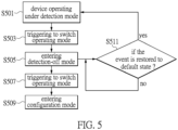
- Fig. 5 is a flowchart illustrating the operating method of the sensor device according to another embodiment of the present invention.
- the sensor device begins to operate under the detection mode (step S501). At this time, the user can switch the operating modes of the sensor device by a button or a touch interface (step S503).
- the sensor device currently enters a detection-off mode (step S505), which allows the sensor device to enter a power-saving mode until being switched to a next operating mode (step S507).
- the sensor device enters the configuration mode (step S509), in which the user is allowed to set the operating parameters of the sensor device by the configuration device, or to retrieve information of the operating states of the sensor device and the recorded events.
- step S505 when the sensor device enters the detection-off mode, the sensor device can operate with a basic power supply for detecting if the event of the firearm being pulled out of the holster is restored to the default state (step S511). That is, whether or not the firearm is placed back to the holster. If the event is not restored to the default state, the microcontroller repeats step S511 for determining if the event is restored to the default state. If the event is determined to be restored to the default state, the process returns to step S501 for switching the detection-off mode to the detection mode, and the sensor device may operate under the detection mode.
- the default state indicates that the firearm is placed back to the holster.
- the sensor device can be automatically switched from the detection-off mode to the detection mode.
- the user can enable the sensor device to return to the default state by pushing the button or touching the touch interface. Once the user pushes the button, the sensor device can be switched from the detection-off mode to the configuration mode, and then back to the detection mode.
- Fig. 6 is a flowchart illustrating operation between a sensor device 63, an audiovisual device 61, and a configuration device 62.
- the sensor device 63 can operate under a configuration mode 631, a broadcast mode 633, a detection mode 635, or a detection-off mode 637.
- the sensor device 63 When the sensor device 63 enters the broadcast mode 633, the sensor device 63 starts to broadcast a trigger signal that is generated when the event is detected (step S611).
- the audiovisual device 61 can be activated to start the recording function for capturing images upon receiving the trigger signal (step S613).
- the sensor device 63 When the sensor device 63 enters the broadcast mode 633, the sensor device 63 starts a timeout determination. Once the broadcast mode 633 of the sensor device 63 is determined to exceed a timeout period, the sensor device 63 is switched to the detection mode 635 (step S615). Under the detection mode 635, the sensor device 63 detects that the event is restored to the default state (step S617). For example, the firearm is detected to be placed in the holster. It should be noted that, when the event is detected to be restored to the default state, the microcontroller can reset the sensor device to the detection mode, and the sensor device is on standby for detecting if the event occurs.
- the user can push the button to enable the sensor device 63 to enter the detection-off mode 637 (step S619).
- the sensor device 63 can enter the power-saving mode when the sensor device 63 is under the detection mode 635 or the detection-off mode 637.
- the sensor device 63 can then enter the configuration mode 631 once the button is pushed again.
- the sensor device 63 can continue to detect the event with a minimum power supply.
- the sensor device 63 detects the event under the detection-off mode 637 (step S621), e.g., the firearm is pulled out of the holster, and then the sensor device 63 enters the broadcast mode 633 (step S623).
- the trigger signal is generated again, and can be broadcasted (step S625).
- the recording function of the audiovisual device 61 can be activated when the trigger signal is received (step S627). Afterwards, the above process is repeated.
- the sensor device can be configured to operate under multiple operating modes.
- the sensor device When the sensor device is applied to an application of detecting a firearm and activating operation of an audiovisual device, the sensor device provides a solution for automatic operations based on an event of the firearm being pulled out or not pulled out of a holster.
- the battery-powered sensor device can temporarily enter a power-saving mode by switching to any of the operating modes, provide information of electric quantity through lights, and allow a user to set operating parameters of the sensor device.
Landscapes
- Engineering & Computer Science (AREA)
- Multimedia (AREA)
- Signal Processing (AREA)
- Theoretical Computer Science (AREA)
- General Engineering & Computer Science (AREA)
- Physics & Mathematics (AREA)
- General Physics & Mathematics (AREA)
- Health & Medical Sciences (AREA)
- General Health & Medical Sciences (AREA)
- Radar, Positioning & Navigation (AREA)
- Remote Sensing (AREA)
- Computer Networks & Wireless Communication (AREA)
- Social Psychology (AREA)
- Computer Hardware Design (AREA)
- Automation & Control Theory (AREA)
- Human Computer Interaction (AREA)
- Databases & Information Systems (AREA)
- Software Systems (AREA)
- Biophysics (AREA)
- Analytical Chemistry (AREA)
- Neurosurgery (AREA)
- Chemical & Material Sciences (AREA)
- Life Sciences & Earth Sciences (AREA)
- Biomedical Technology (AREA)
- Liquid Crystal Display Device Control (AREA)
- Fittings On The Vehicle Exterior For Carrying Loads, And Devices For Holding Or Mounting Articles (AREA)
- User Interface Of Digital Computer (AREA)
- Television Signal Processing For Recording (AREA)
- Devices For Indicating Variable Information By Combining Individual Elements (AREA)
- Photometry And Measurement Of Optical Pulse Characteristics (AREA)
- Electronic Switches (AREA)
Abstract
A sensor device (300) and an operating method thereof are provided. The sensor device (300) includes a microcontroller (301) and a sensor module. The microcontroller (301) performs the operating method. Firstly, the sensor device (300) enters a configuration mode after being activated. The sensor device (300) enters a detection mode after a timeout period. The sensor device (300) is on standby for detecting if any event occurs under the detection mode. When any event is detected, a trigger signal is generated, and the sensor device (300) enters a broadcast mode to broadcast the trigger signal. After another timeout period, the sensor device (300) enters the detection mode again, and is on standby for detecting if the event is restored to a default state. When the event is restored to the default state, the sensor device (300) is reset for detecting if the event occurs.
Description
- The present invention relates to a sensor technology, and more particularly to a sensor device that performs a process for automatically switching operating modes in order to trigger a specific application and an operating method thereof.
- Currently, security guards, soldiers, or police officers who are required to carry guns or any weapon often wear body cameras at the same time. The body camera can be used to completely record images/videos of the person using the gun or any weapon. These images can be used to resolve future disputes associated with use of the gun. In one further application, these images can also be uploaded to a control center that supports the services of the security guards, the soldiers, or the police officers, so that assistance can be quickly provided in the case of emergencies.
- In the conventional technology, the person wearing the body camera needs to manipulate the body camera himself to record videos. However, since the person may forget to activate the body camera for recording videos in dangerous situations, or fail to record key images in time, the function of the body camera is limited.
- In response to the above-referenced technical inadequacies, the present invention provides a sensor device and an operating method thereof that are capable of triggering a sensor for a specific application in time. The sensor device includes a microcontroller that is used to control operation of the sensor device. For example, the microcontroller controls a sensor module of the sensor device to sense a specific event.
- In the operating method that is performed by the microcontroller of the sensor device, the sensor device is activated to firstly enter a configuration mode after a power is turned on. After a timeout period, the sensor device enters a detection mode, allowing the sensor device to be on standby for detecting if any event occurs. Under the detection mode, a trigger signal is generated when the sensor device detects the event. In the meantime, the sensor device enters a broadcast mode for broadcasting the trigger signal. After another timeout period, the sensor device enters the detection mode again, and is on standby for detecting if the event is restored to a default state.
- Further, when the sensor device is under the configuration mode, the sensor device connects with a configuration device via a communication protocol. The configuration device is used to set operating parameters of the sensor device or to retrieve information of operating states and recorded events from the sensor device.
- Further, when the sensor device is under the broadcast mode, the sensor device broadcasts the trigger signal via a near-end communication protocol, and a recording function of one or more audiovisual devices is activated after receiving the trigger signal.
- Further, when the sensor device detects that the event is restored to the default state under the detection mode, the sensor device is reset and on standby for detecting if the event occurs.
- Further, when the sensor device is under the detection mode, the sensor device can enter a detection-off mode if a button of the sensor device is pushed. If the event is detected to be restored to the default state, the sensor device is automatically switched from the detection-off mode to the detection mode.
- Moreover, when the sensor device is under the detection mode or the detection-off mode, the sensor device will enter a power-saving mode.
- In one embodiment of the present invention, the sensor device can be disposed on a holster for detecting whether or not a firearm is pulled out from the holster. If the sensor device detects that the firearm is pulled out from holster, the event occurs, and the trigger signal that includes information of the event and a timestamp of the event is formed. The trigger signal is broadcasted when the sensor device is under the broadcast mode.
- Further, when the sensor device is under the broadcast mode and exceeds the timeout period, the sensor device will be switched to the detection mode. When the sensor device detects that the firearm is placed in the holster and the event is restored to the default state under the detection mode, the sensor device is reset and on standby for detecting if the event occurs.
- These and other aspects of the present invention will become apparent from the following description of the embodiment taken in conjunction with the following drawings and their captions, although variations and modifications therein may be affected without departing from the spirit and scope of the novel concepts of the invention.
- The described embodiments may be better understood by reference to the following description and the accompanying drawings, in which:
-
Fig. 1 is a schematic diagram illustrating a sensor device and cooperative peripheral devices connected thereto according to one embodiment of the present invention; -
Fig. 2 is a schematic diagram illustrating the sensor device and the cooperative peripheral devices according to another embodiment of the present invention; -
Fig. 3 is a schematic diagram illustrating circuit components of the sensor device according to one embodiment of the present invention; -
Fig. 4 is a flowchart illustrating an operating method of the sensor device according to one embodiment of the present invention; -
Fig. 5 is a flowchart illustrating the operating method of the sensor device according to another embodiment of the present invention; and -
Fig. 6 is a flowchart illustrating operation between the sensor device, an audiovisual device, and a configuration device according to one embodiment of the present invention. - The present disclosure is more particularly described in the following examples that are intended as illustrative only since numerous modifications and variations therein will be apparent to those skilled in the art. Like numbers in the drawings indicate like components throughout the views. As used in the description herein and throughout the claims that follow, unless the context clearly dictates otherwise, the meaning of "a," "an" and "the" includes plural reference, and the meaning of "in" includes "in" and "on." Titles or subtitles can be used herein for the convenience of a reader, which shall have no influence on the scope of the present disclosure.
- The terms used herein generally have their ordinary meanings in the art. In the case of conflict, the present document, including any definitions given herein, will prevail. The same thing can be expressed in more than one way. Alternative language and synonyms can be used for any term(s) discussed herein, and no special significance is to be placed upon whether a term is elaborated or discussed herein. A recital of one or more synonyms does not exclude the use of other synonyms. The use of examples anywhere in this specification including examples of any terms is illustrative only, and in no way limits the scope and meaning of the present disclosure or of any exemplified term. Likewise, the present disclosure is not limited to various embodiments given herein. Numbering terms such as "first," "second" or "third" can be used to describe various components, signals or the like, which are for distinguishing one component/signal from another one only, and are not intended to, nor should be construed to impose any substantive limitations on the components, signals or the like.
- The present invention relates to a sensor device and an operating method. The sensor device is a sensor consisting of induction coils. The sensor device applies an electromagnetic induction principle (i.e., movement of a nearby metal object will induce change in inductance), so that the sensor device can sense change in position of a nearby metal object.
- Reference is made to
Fig. 1 , which is a schematic diagram illustrating a sensor device and cooperatively connected peripheral devices according to one embodiment of the present invention. - In the diagram, a
sensor device 100 is mounted on aholster 110. One of the objectives of thesensor device 100 is to detect whether or not afirearm 120 is pulled out of theholster 110. In an operating method of thesensor device 100, thesensor device 100 is mounted on a surface of theholster 110, and is able to sense a presence of thefirearm 120. According to one embodiment of the present invention, thefirearm 120 can be equipped with asensor accessory 130. Thesensor accessory 130 is preferably a metal object. The position of thesensor accessory 130 attached to thefirearm 120 should correspond to the position of thesensor device 100 on theholster 110. The movement of the firearm 120 (being pulled out of or placed in the holster 110) will drive thesensor accessory 130 to move, thereby allowing thesensor device 100 to sense change in inductance. Therefore, a control circuit of thesensor device 100 can determine if thefirearm 120 is pulled out of or placed in theholster 110 according to the change in inductance. It should be noted that thesensor device 100 applies the electromagnetic induction principle to detect a status of thefirearm 120. Thesensor accessory 130 can be adapted to a non-metallic firearm, or can be used when the position corresponding to the position of thesensor device 100 on theholster 110 is non-metallic. It should be noted that it is unnecessary to use thesensor accessory 130 if the body of thefirearm 120 is metallic. When themetallic firearm 120 is pulled out of or placed in theholster 110, thesensor device 100 can sense the change in inductance. -
Fig. 1 schematically shows a person (e.g., a police officer on duty) who carries thefirearm 120 and anaudiovisual device 150 at the same time. In the present embodiment, a special event occurs when thesensor device 100 determines that thefirearm 120 is pulled out of theholster 110, and a control circuit of thesensor device 100 generates a signal to activate operation of theaudiovisual device 150. For example, a recording function of theaudiovisual device 150 is activated, so as to start capturing images through acamera lens 151. Theaudiovisual device 150 is activated to record a live video of the police officer who uses thefirearm 120. Theaudiovisual device 150 also provides acontrol interface 153, so that a user may manipulate functions of the audiovisual device 150 (e.g., to start recording a live video or to stop recording). -
Fig. 2 shows a schematic diagram illustrating the sensor device and the cooperatively connected peripheral devices according to another embodiment of the present invention. A person shown in the diagram wears theaudiovisual device 150. Thesensor device 100 is disposed on theholster 110 that includes thefirearm 120. Thesensor device 100 is used to sense change in position of thefirearm 120. - The
sensor device 100 operates according to the above embodiments. When thesensor device 100 disposed on theholster 110 detects that thefirearm 120 is pulled out of theholster 110, the event detected by the sensor device is formed. A trigger signal that includes information of the event and a timestamp of the event is formed. The trigger signal is broadcasted through a near-end communication protocol when thesensor device 100 is under the broadcast mode. After being broadcasted, the trigger signal is received by one or moreaudiovisual devices 150. Then, theaudiovisual device 150 is triggered to operate. An in-caraudiovisual system 210 in avehicle 200 can also be triggered by the trigger signal to operate. Image data related to the event can be transmitted to acontrol center 220 by theaudiovisual device 150. Thecontrol center 220 then makes a record of the event. - In one embodiment of the present invention, the
sensor device 100 disposed on theholster 110 senses that thefirearm 120 is pulled out of theholster 110 at a time when, for example, a police officer is on duty and needs to use thefirearm 120 in a specific event. In the meantime, a trigger signal is generated and broadcasted to a nearby device, thereby triggering theaudiovisual device 150 to start recording. The in-caraudiovisual system 210 can also be triggered to start operating upon receiving the trigger signal. Further, the in-caraudiovisual system 210 can trigger the audiovisual device worn by a nearby person to start operating, or download a video recorded by the nearby audiovisual device. In addition, the video can be transmitted to thecontrol center 220 via a communication capability of theaudiovisual device 150 or the in-caraudiovisual system 210. -
Fig. 3 is a schematic diagram illustrating circuit components of the sensor device according to one embodiment of the present invention. - A
sensor device 300 shown in the diagram mainly includes amicrocontroller 301 and a sensor module that is electrically connected with themicrocontroller 301. The sensor module is composed of one or more induction coils that are configured to sense an event. The sensor module implements a proximity sensor or a differential inductance sensor. The sensor module applies the electromagnetic induction principle to sense a specific event. As mentioned above, the sensor module is able to sense if the firearm is pulled out of or placed in the holster via a corresponding sensor accessory. - The
microcontroller 301 is used to control operation of thesensor device 300, and operating modes of the sensor device will be switched automatically according to the operating method. Thesensor device 300 includes acommunication unit 305 that is used to issue broadcast signals or connect with an external device such as a configuration device 31. Thecommunication unit 305 can be implemented by a BLUETOOTH® low energy (BLE) component. Thesensor device 300 includes asensor element 307 consisting of induction coils. Thesensor element 307 is used to sense changes of a nearby sensor accessory (e.g., a metal accessory). Thesensor device 300 has acontrol interface 303. Thecontrol interface 303 can be a button or a touch interface that allows the user to manipulate thesensor device 300. For example, the user can manually switch the operating modes of the sensor device, turn on the power, or shut down the device via thecontrol interface 303. Thesensor device 300 includes apower management unit 308 that is used to manage power supply to thesensor device 300. - According to one embodiment of the operating method of the
sensor device 300, themicrocontroller 301 controls thesensor device 300 to be operated under aconfiguration mode 311, abroadcast mode 313, adetection mode 315, and a detection-off mode 317. Thesensor device 300 can detect movement of an object to be detected 33 under thedetection mode 315. Thesensor device 300 can connect with the external configuration device 31 via a communication protocol under theconfiguration mode 311, so that the configuration device 31 can be used to set operating parameters of thesensor device 300, or to retrieve operating states of thesensor device 300 and the recorded events for external monitoring. When thesensor device 300 detects a specific event, thesensor device 300 is switched to thebroadcast mode 313 for broadcasting signals, so that anaudiovisual device 35 is activated to operate. In one embodiment, the configuration device 31 can be used to set up groups via a user interface. For example, multiple ones of theaudiovisual devices 35 can be grouped and assigned with a group ID. If any of the firearms in the same group is detected to be pulled out of the holster, theaudiovisual devices 35 with the same group ID can be activated to start recording at the same time upon receiving the same broadcast signals. - Reference is made to
Fig. 4 , which is a flowchart illustrating the operating method of the sensor device according to one embodiment of the present invention. Firstly, the sensor device can be powered and activated by a battery. In one embodiment, the sensor device uses a measurement circuit to measure electric quantity of the battery. After the sensor device is activated, the microcontroller of the sensor device can trigger lights of the sensor device to flash or change colors according to the electric quantity of the battery. - In the meantime, the sensor device enters the configuration mode (step S401), and connects with the configuration device. The configuration device is used to set the operating parameters of the sensor device and to retrieve operating records of the sensor device. Under the configuration mode, a timer of the sensor device continues to operate. The microcontroller relies on the timer to determine if a timeout threshold (e.g., 30 seconds) is reached. In step S403, if the microcontroller determines that the timeout threshold is not yet exceeded, the sensor device can still be under the configuration mode. Conversely, if the microcontroller determines that the timeout threshold is exceeded, the sensor device enters the detection mode (step S405) for detecting if any event occurs (step S407).
- According to one embodiment of the present invention, when the sensor device is used for firearm detection, the event indicates that the firearm is pulled out of the holster. If there is no event to be detected, step S407 is repeated for detecting if any event occurs. If the event is detected, the microcontroller generates a trigger signal (step S409), and the sensor device enters the broadcast mode (step S411) for broadcasting the trigger signal (step S413).
- When the sensor device is under the broadcast mode, the sensor device also activates the timer for determining if the broadcast mode exceeds a timeout period (step S415). If the timeout period is not yet exceeded, the sensor device remains under the broadcast mode, such as in step S413. If the microcontroller determines that the timeout period is exceeded, the sensor device enters the detection mode (step S417). In the meantime, the sensor device is on standby for detecting if the event is restored to a default state (step S419). That is, the sensor device detects if the firearm is placed in the holster according to change in inductance. If the event is not yet restored to the default state, the sensor device continues to determine if the event is restored to the default state. If the sensor device detects that the event has been restored to the default state (i.e., the firearm is placed in the holster according to the above-mentioned embodiment), the sensor device is reset to be operated under the detection mode (step S421).
- Reference is made to
Fig. 5 , which is a flowchart illustrating the operating method of the sensor device according to another embodiment of the present invention. - In the present flowchart, the sensor device begins to operate under the detection mode (step S501). At this time, the user can switch the operating modes of the sensor device by a button or a touch interface (step S503). The sensor device currently enters a detection-off mode (step S505), which allows the sensor device to enter a power-saving mode until being switched to a next operating mode (step S507). In the meantime, the sensor device enters the configuration mode (step S509), in which the user is allowed to set the operating parameters of the sensor device by the configuration device, or to retrieve information of the operating states of the sensor device and the recorded events.
- It should be noted that the user can enable the sensor device to enter the detection-off mode by pushing the button or touching the touch interface. The detection-off mode does not mean not detecting whether the firearm is in the holster or is pulled out of the holster, but not activating the recording function even if a specific event is detected. For example, the detection-off mode mainly defines a period of time during which the user may clean the firearm, maintain the firearm, or store the firearm in a firearm cabinet. During this period, the sensor device will not activate the recording function when the firearm is pulled out of the holster.
- Furthermore, in step S505, when the sensor device enters the detection-off mode, the sensor device can operate with a basic power supply for detecting if the event of the firearm being pulled out of the holster is restored to the default state (step S511). That is, whether or not the firearm is placed back to the holster. If the event is not restored to the default state, the microcontroller repeats step S511 for determining if the event is restored to the default state. If the event is determined to be restored to the default state, the process returns to step S501 for switching the detection-off mode to the detection mode, and the sensor device may operate under the detection mode.
- In an exemplary example where the sensor device detects if the firearm is pulled out of the holster, the default state indicates that the firearm is placed back to the holster. For example, when maintenance of the firearm is completed or the firearm is taken out from the firearm cabinet, the sensor device can be automatically switched from the detection-off mode to the detection mode. Alternatively, when the firearm is placed back to the holster, the user can enable the sensor device to return to the default state by pushing the button or touching the touch interface. Once the user pushes the button, the sensor device can be switched from the detection-off mode to the configuration mode, and then back to the detection mode.
- Reference is made to
Fig. 6 , which is a flowchart illustrating operation between asensor device 63, anaudiovisual device 61, and aconfiguration device 62. Thesensor device 63 can operate under aconfiguration mode 631, abroadcast mode 633, adetection mode 635, or a detection-off mode 637. - The
sensor device 63 firstly enters theconfiguration mode 631 when thesensor device 63 is activated. Theconfiguration device 62 sets operating parameters of thesensor device 63, or retrieves data of the sensor device 63 (step S601). In the meantime, thesensor device 63 determines if theconfiguration mode 631 exceeds a timeout period. If the timeout period is exceeded, thesensor device 63 enters the detection mode 635 (step S603). - Under the
detection mode 635, thesensor device 63 can be switched to one of the various operating modes by pushing a button or detecting any event. Firstly, when the button of thesensor device 63 is pushed, thesensor device 63 enters the detection-off mode 637 (step S605). Secondly, when thesensor device 63 is under thedetection mode 635, thesensor device 63 can be switched to theconfiguration mode 631 if the button is pushed (step S607). Thirdly, when thesensor device 63 is under thedetection mode 635 and detects that an event (such as the firearm being pulled out of the holster) occurs, thesensor device 63 enters the broadcast mode 633 (step S609). - When the
sensor device 63 enters thebroadcast mode 633, thesensor device 63 starts to broadcast a trigger signal that is generated when the event is detected (step S611). Theaudiovisual device 61 can be activated to start the recording function for capturing images upon receiving the trigger signal (step S613). - When the
sensor device 63 enters thebroadcast mode 633, thesensor device 63 starts a timeout determination. Once thebroadcast mode 633 of thesensor device 63 is determined to exceed a timeout period, thesensor device 63 is switched to the detection mode 635 (step S615). Under thedetection mode 635, thesensor device 63 detects that the event is restored to the default state (step S617). For example, the firearm is detected to be placed in the holster. It should be noted that, when the event is detected to be restored to the default state, the microcontroller can reset the sensor device to the detection mode, and the sensor device is on standby for detecting if the event occurs. - In the meantime, the user can push the button to enable the
sensor device 63 to enter the detection-off mode 637 (step S619). According to one of the embodiments of the present invention, thesensor device 63 can enter the power-saving mode when thesensor device 63 is under thedetection mode 635 or the detection-off mode 637. Thesensor device 63 can then enter theconfiguration mode 631 once the button is pushed again. Furthermore, under the detection-off mode 637, thesensor device 63 can continue to detect the event with a minimum power supply. - In the present example, the
sensor device 63 detects the event under the detection-off mode 637 (step S621), e.g., the firearm is pulled out of the holster, and then thesensor device 63 enters the broadcast mode 633 (step S623). The trigger signal is generated again, and can be broadcasted (step S625). The recording function of theaudiovisual device 61 can be activated when the trigger signal is received (step S627). Afterwards, the above process is repeated. - In conclusion, according to the above embodiments of the sensor device and the operating method provided by the present invention, the sensor device can be configured to operate under multiple operating modes. When the sensor device is applied to an application of detecting a firearm and activating operation of an audiovisual device, the sensor device provides a solution for automatic operations based on an event of the firearm being pulled out or not pulled out of a holster. Furthermore, the battery-powered sensor device can temporarily enter a power-saving mode by switching to any of the operating modes, provide information of electric quantity through lights, and allow a user to set operating parameters of the sensor device.
- The foregoing description of the exemplary embodiments of the invention has been presented only for the purposes of illustration and description and is not intended to be exhaustive or to limit the invention to the precise forms disclosed. Many modifications and variations are possible in light of the above teaching.
- The embodiments were chosen and described in order to explain the principles of the invention and their practical application so as to enable others skilled in the art to utilize the invention and various embodiments and with various modifications as are suited to the particular use contemplated. Alternative embodiments will become apparent to those skilled in the art to which the present invention pertains without departing from its spirit and scope.
Claims (15)
- An operating method of a sensor device (300), characterized in that the operating method comprises:entering the sensor device (300) into a configuration mode after the sensor device (300) is activated;entering the sensor device (300) into a detection mode after a timeout period, wherein the sensor device (300) is on standby for detecting whether or not an event occurs while in the detection mode;forming a trigger signal when the sensor device (300) detects the event while in the detection mode, and entering the sensor device into a broadcast mode for broadcasting the trigger signal; andentering the sensor device (300) into the detection mode after another timeout period, wherein the sensor device (300) is on standby for detecting whether or not the event is restored to a default state while in the detection mode.
- The operating method according to claim 1, wherein the configuration mode is provided for a configuration device (31) to set operating parameters of the sensor device (300) or to retrieve information of operating states of the sensor device (300) and recorded events.
- The operating method according to claim 1, wherein:when the sensor device (300) detects that the event is restored to the default state while in the detection mode, the operating method comprises resetting the sensor device (300), andonce reset, the sensor device (300) is on standby for detecting whether or not the event occurs.
- The operating method according to claim 1, wherein, when a button of the sensor device (300) is pushed while in the detection mode, the operating method comprises:entering the sensor device (300) into a detection-off mode; andafter the button is pushed again, entering the sensor device (300) into the configuration mode.
- The operating method according to claim 4, wherein, when the sensor device (300) is in the detection-off mode, the operating method comprises switching the sensor device (300) to the detection mode in response to the event being restored to the default state.
- The operating method according to claim 1, wherein:the sensor device (300) is powered and activated by a battery; andafter the sensor device (300) is activated, the operating method comprises triggering lights of the sensor device (300) to flash according to an electric quantity of the battery.
- The operating method according to any of claim 1 to claim 6, wherein:the sensor device (300) is disposed on a holster (110) and used for detecting whether or not a firearm is pulled out of the holster (110);forming the trigger signal comprises forming the trigger signal in response to detecting that the firearm is pulled out of the holster (110), which is the event,the trigger signal comprises information of the event and a timestamp of the event; andthe operating method comprises broadcasting the trigger signal when the sensor device (300) is in the broadcast mode.
- The operating method according to claim 7, comprising:
activating a recording function of one or more audiovisual devices (35) upon receiving the trigger signal broadcast from the sensor device (300) while the sensor device is in the broadcast mode. - The operating method according to claim 7, comprising:switching the sensor device (300) from the broadcast mode to the detection mode when the timeout period is exceeded; andwhen the sensor device (300) detects that the firearm is placed in the holster (110) and the event is restored to the default state while in the detection mode, resetting the sensor device (300), wherein the sensor device (300) is on standby for detecting whether or not the event occurs.
- A sensor device (300), characterized in that the sensor device comprises:a microcontroller (301); anda sensor module electrically connected with the microcontroller (301), wherein the sensor module is used to sense an event;wherein the microcontroller (301) performs an operating method of the sensor device (300), and the operating method comprises:entering the sensor device (300) into a configuration mode after the sensor device (300) is activated;entering the sensor device (300) into enter a detection mode after a timeout period, wherein the sensor device (300) is on standby for detecting whether or not the event occurs while in the detection mode;forming a trigger signal when the sensor device (300) detects the event while in the detection mode, and entering the sensor device (300) into a broadcast mode for broadcasting the trigger signal; andentering the sensor device (300) into the detection mode after another timeout period, wherein the sensor device (300) is on standby for detecting whether or not the event is restored to a default state while in the detection mode.
- The sensor device (300) according to claim 10, wherein:when the sensor device (300) is in the configuration mode, the sensor device (300) connects with a configuration device (31) via a communication protocol, andthe configuration device (31) is used to set operating parameters of the sensor device (300) or to retrieve information of operating states of the sensor device (300) and recorded events.
- The sensor device (300) according to claim 10, wherein:the sensor device (300) broadcasts the trigger signal through a near-end communication protocol while in the broadcast mode, anda recording function of one or more audiovisual devices (35) is activated upon receiving the trigger signal.
- The sensor device (300) according to claim 10, wherein:when the sensor device (300) detects that the event is restored to the default state while in the detection mode, the operating method comprises resetting the sensor device (300), and once reset, the sensor device (300) is on standby for detecting whether or not the event occurs;the operating method comprises switching the sensor device (300) to a detection-off mode by pushing a button of the sensor device (300);in response to the event being restored to the default state, the operating method comprises switching the sensor device (300) from the detection-off mode to the detection mode; andwhen the sensor device (300) is in the detection mode or in the detection-off mode, the operating method comprises entering the sensor device (300) into a power-saving mode.
- The sensor device (300) according to any of claim 10 to claim 13, wherein:the sensor device (300) is disposed on a holster (110) and used for detecting whether or not a firearm is pulled out of the holster (110);in response to detecting that the firearm is pulled out of the holster (110), the event occurs, and the trigger signal that comprises information of the event and a timestamp of the event is formed; andthe trigger signal is broadcasted when the sensor device (300) is in the broadcast mode.
- The sensor device (300) according to claim 14, wherein:the sensor device (300) is switched from the broadcast mode to the detection mode after the timeout period; andwhen the sensor device (300) detects that the firearm is placed in the holster (110) and the event is restored to the default state while in the detection mode, the operating method comprises resetting the sensor device (300) , and once reset the sensor device (300) is on standby for detecting whether or not the event occurs.
Applications Claiming Priority (1)
| Application Number | Priority Date | Filing Date | Title |
|---|---|---|---|
| US202363527509P | 2023-07-18 | 2023-07-18 |
Publications (1)
| Publication Number | Publication Date |
|---|---|
| EP4496305A1 true EP4496305A1 (en) | 2025-01-22 |
Family
ID=89029590
Family Applications (3)
| Application Number | Title | Priority Date | Filing Date |
|---|---|---|---|
| EP23213192.0A Pending EP4494945A1 (en) | 2023-07-18 | 2023-11-30 | Scalable in-vehicle video system and signal control apparatus |
| EP23213642.4A Pending EP4496305A1 (en) | 2023-07-18 | 2023-12-01 | Sensor device and operating method thereof |
| EP24153118.5A Pending EP4495739A1 (en) | 2023-07-18 | 2024-01-22 | Adaptive display backlight control system and method for controlling the backlight |
Family Applications Before (1)
| Application Number | Title | Priority Date | Filing Date |
|---|---|---|---|
| EP23213192.0A Pending EP4494945A1 (en) | 2023-07-18 | 2023-11-30 | Scalable in-vehicle video system and signal control apparatus |
Family Applications After (1)
| Application Number | Title | Priority Date | Filing Date |
|---|---|---|---|
| EP24153118.5A Pending EP4495739A1 (en) | 2023-07-18 | 2024-01-22 | Adaptive display backlight control system and method for controlling the backlight |
Country Status (4)
| Country | Link |
|---|---|
| US (4) | US12587740B2 (en) |
| EP (3) | EP4494945A1 (en) |
| AU (3) | AU2023270306A1 (en) |
| TW (2) | TWI867768B (en) |
Families Citing this family (1)
| Publication number | Priority date | Publication date | Assignee | Title |
|---|---|---|---|---|
| US12587699B2 (en) * | 2024-01-24 | 2026-03-24 | Nissan North America, Inc. | Synchronizing playback of multimedia between in-vehicle and mobile devices |
Citations (6)
| Publication number | Priority date | Publication date | Assignee | Title |
|---|---|---|---|---|
| US20160165192A1 (en) * | 2014-12-08 | 2016-06-09 | Amirbahman Saatchi | Methods, systems, and apparatuses for capturing and archiving firearm event telemetry and environmental conditions |
| US20170054951A1 (en) * | 2015-08-21 | 2017-02-23 | Roy L. Weekly | Safety system including a weapon holster and body-worn camera system |
| US20170059274A1 (en) * | 2015-08-25 | 2017-03-02 | Taser International, Inc. | Systems and Methods for Cooperation Among Weapons, Holsters, and Recorders |
| US20180274876A1 (en) * | 2013-04-01 | 2018-09-27 | Yardarm Technologies, Inc. | Telematics sensors and camera activation in connection with firearm activity |
| US20190197354A1 (en) * | 2017-12-22 | 2019-06-27 | Motorola Solutions, Inc | Method, device, and system for adaptive training of machine learning models via detected in-field contextual sensor events and associated located and retrieved digital audio and/or video imaging |
| US20230101332A1 (en) * | 2021-09-30 | 2023-03-30 | Getac Corporation | Automated camera activation |
Family Cites Families (37)
| Publication number | Priority date | Publication date | Assignee | Title |
|---|---|---|---|---|
| JP3882522B2 (en) | 2001-03-29 | 2007-02-21 | セイコーエプソン株式会社 | Mobile device with camera |
| GB2400667B (en) | 2003-04-15 | 2006-05-31 | Hewlett Packard Development Co | Attention detection |
| US7728316B2 (en) * | 2005-09-30 | 2010-06-01 | Apple Inc. | Integrated proximity sensor and light sensor |
| US7633076B2 (en) * | 2005-09-30 | 2009-12-15 | Apple Inc. | Automated response to and sensing of user activity in portable devices |
| US7714265B2 (en) * | 2005-09-30 | 2010-05-11 | Apple Inc. | Integrated proximity sensor and light sensor |
| TWM310381U (en) | 2006-08-14 | 2007-04-21 | Rung-Yuan Wang | Firearms control system |
| US20080061991A1 (en) | 2006-09-11 | 2008-03-13 | Randall Lee Urban | System and method for remote Audio/Video capture of weapon use |
| TWI397898B (en) * | 2008-04-22 | 2013-06-01 | Htc Corp | Portable electronic apparatus and backlight control method thereof |
| RU2493613C2 (en) * | 2008-08-22 | 2013-09-20 | Сони Корпорейшн | Image display device and driving method |
| US20100079508A1 (en) | 2008-09-30 | 2010-04-01 | Andrew Hodge | Electronic devices with gaze detection capabilities |
| US10282563B2 (en) | 2009-02-06 | 2019-05-07 | Tobii Ab | Video-based privacy supporting system |
| JP5299866B2 (en) | 2009-05-19 | 2013-09-25 | 日立コンシューマエレクトロニクス株式会社 | Video display device |
| RU2012140472A (en) | 2010-02-24 | 2014-03-27 | Шарп Кабусики Кайся | LIGHT-RADIATING DEVICE FOR DISPLAYING AN IMAGE AND DEVICE FOR DISPLAYING AN IMAGE |
| US20120169594A1 (en) * | 2010-12-30 | 2012-07-05 | Motorola-Mobility, Inc. | Electronic device and method for backlight control |
| TWI421624B (en) * | 2011-04-01 | 2014-01-01 | Ind Tech Res Inst | Adaptive surrounding view monitoring apparatus and method thereof |
| US9058703B2 (en) * | 2012-03-14 | 2015-06-16 | Flextronics Ap, Llc | Shared navigational information between vehicles |
| CN102842291B (en) * | 2012-09-04 | 2015-09-02 | 济南微晶电子技术有限公司 | A kind of back light adjusting system based on obverse face detection and method |
| CN104133548A (en) * | 2013-05-03 | 2014-11-05 | 中国移动通信集团公司 | Method and device for determining viewpoint area and controlling screen luminance |
| US10619961B2 (en) | 2013-07-01 | 2020-04-14 | Karl F. Milde, Jr. | Apparatus and method for assisting law enforcement in managing crisis situations |
| BR112017014261A2 (en) | 2014-12-29 | 2018-03-06 | PogoTec, Inc. | firearm and holster, head protector and method for wireless power transfer |
| US9613587B2 (en) | 2015-01-20 | 2017-04-04 | Snaptrack, Inc. | Apparatus and method for adaptive image rendering based on ambient light levels |
| TWM509359U (en) | 2015-03-20 | 2015-09-21 | hong-yi Zhang | Photographing guns with wired charging capability and gun sleeve |
| JP6193912B2 (en) * | 2015-04-24 | 2017-09-06 | 株式会社パイ・アール | Drive recorder |
| TWM518656U (en) * | 2015-12-07 | 2016-03-11 | Dynamas Technology Corp | Car interior audio-video monitoring system |
| CN105677042A (en) * | 2016-02-24 | 2016-06-15 | 广东欧珀移动通信有限公司 | Control method and device for display mode of terminal |
| US11280582B2 (en) | 2016-11-30 | 2022-03-22 | James Clinton Estes, III | Pistol activity recording device |
| KR102790278B1 (en) * | 2016-12-22 | 2025-04-03 | 삼성전자주식회사 | Apparatus and method for Display |
| US10324525B2 (en) * | 2016-12-31 | 2019-06-18 | Intel Corporation | Context aware selective backlighting techniques |
| US20210172716A1 (en) | 2017-02-06 | 2021-06-10 | Check 6 Tactical & Training, LLC | Gun video camera system |
| US11385022B2 (en) * | 2017-02-14 | 2022-07-12 | Axon Enterprise, Inc. | Mounting systems and methods for positioning a detector on a weapon holster |
| WO2019022717A1 (en) * | 2017-07-25 | 2019-01-31 | Hewlett-Packard Development Company, L.P. | Determining user presence based on sensed distance |
| CN108646907A (en) | 2018-04-18 | 2018-10-12 | Oppo广东移动通信有限公司 | Backlight brightness adjusting method and related product |
| JP2022534338A (en) * | 2019-03-27 | 2022-07-29 | インテル コーポレイション | Smart display panel device and related method |
| WO2021258394A1 (en) | 2020-06-26 | 2021-12-30 | Intel Corporation | Systems, methods, and apparatus for display panel human presence detection |
| CN112683108B (en) | 2020-12-29 | 2024-02-27 | 卢祺 | Weapon supervision method and device, storage medium and electronic device |
| US20230209156A1 (en) * | 2021-12-27 | 2023-06-29 | Digital Barriers Services, Ltd. | Methods and Systems for Managing Body-Worn Video Recording Devices |
| CN115695695A (en) | 2022-10-31 | 2023-02-03 | 深圳泰美威视科技有限公司 | Firearms Recording Device and Law Enforcement Recording System |
-
2023
- 2023-09-28 TW TW112137220A patent/TWI867768B/en active
- 2023-10-02 TW TW112137609A patent/TWI866509B/en active
- 2023-11-23 AU AU2023270306A patent/AU2023270306A1/en not_active Abandoned
- 2023-11-24 US US18/518,679 patent/US12587740B2/en active Active
- 2023-11-29 US US18/522,608 patent/US20250030942A1/en active Pending
- 2023-11-30 AU AU2023274162A patent/AU2023274162A1/en not_active Abandoned
- 2023-11-30 EP EP23213192.0A patent/EP4494945A1/en active Pending
- 2023-12-01 EP EP23213642.4A patent/EP4496305A1/en active Pending
- 2023-12-01 US US18/526,145 patent/US12347395B2/en active Active
-
2024
- 2024-01-22 EP EP24153118.5A patent/EP4495739A1/en active Pending
-
2025
- 2025-06-02 US US19/225,136 patent/US20250294248A1/en active Pending
- 2025-08-15 AU AU2025217384A patent/AU2025217384A1/en active Pending
Patent Citations (6)
| Publication number | Priority date | Publication date | Assignee | Title |
|---|---|---|---|---|
| US20180274876A1 (en) * | 2013-04-01 | 2018-09-27 | Yardarm Technologies, Inc. | Telematics sensors and camera activation in connection with firearm activity |
| US20160165192A1 (en) * | 2014-12-08 | 2016-06-09 | Amirbahman Saatchi | Methods, systems, and apparatuses for capturing and archiving firearm event telemetry and environmental conditions |
| US20170054951A1 (en) * | 2015-08-21 | 2017-02-23 | Roy L. Weekly | Safety system including a weapon holster and body-worn camera system |
| US20170059274A1 (en) * | 2015-08-25 | 2017-03-02 | Taser International, Inc. | Systems and Methods for Cooperation Among Weapons, Holsters, and Recorders |
| US20190197354A1 (en) * | 2017-12-22 | 2019-06-27 | Motorola Solutions, Inc | Method, device, and system for adaptive training of machine learning models via detected in-field contextual sensor events and associated located and retrieved digital audio and/or video imaging |
| US20230101332A1 (en) * | 2021-09-30 | 2023-03-30 | Getac Corporation | Automated camera activation |
Also Published As
| Publication number | Publication date |
|---|---|
| US20250294248A1 (en) | 2025-09-18 |
| TWI866509B (en) | 2024-12-11 |
| TW202505896A (en) | 2025-02-01 |
| US20250027748A1 (en) | 2025-01-23 |
| US20250029568A1 (en) | 2025-01-23 |
| AU2023274162A1 (en) | 2025-02-06 |
| EP4494945A1 (en) | 2025-01-22 |
| EP4495739A1 (en) | 2025-01-22 |
| TWI867768B (en) | 2024-12-21 |
| TW202505274A (en) | 2025-02-01 |
| US20250030942A1 (en) | 2025-01-23 |
| AU2025217384A1 (en) | 2025-09-04 |
| US12587740B2 (en) | 2026-03-24 |
| US12347395B2 (en) | 2025-07-01 |
| AU2023270306A1 (en) | 2025-02-06 |
Similar Documents
| Publication | Publication Date | Title |
|---|---|---|
| US11750032B2 (en) | Gun-mounted recording device | |
| KR100573936B1 (en) | Image sensing apparatus, image processing apparatus, and control method therefor | |
| US5412425A (en) | Electronic still camera with power conservation facility | |
| US8756850B2 (en) | Firearm with interface modules for firearms | |
| EP0585033A1 (en) | Automatic surveillance camera equipment and alarm system | |
| WO2018071901A1 (en) | Gun-mounted recording device with auto on | |
| US12587740B2 (en) | Sensor device and operating method thereof | |
| US20170268842A1 (en) | Firearm-safety-sensing camera-light-laser system and method | |
| US5313305A (en) | Video camera having viewfinder and a power saving function feature | |
| KR102067905B1 (en) | Automatic photographing system of usage of firearms | |
| EP2958315B1 (en) | Camera device and method for controlling a camera device | |
| KR101037328B1 (en) | Imaging Device and Control Method | |
| US7187858B2 (en) | Camera and method for operating a camera based upon available power in a supply | |
| US20160142684A1 (en) | Camera apparatus and method | |
| TWI882450B (en) | Sensor device, holster sensing system, and video-recording system | |
| JP2006201957A (en) | Electronic equipment | |
| KR101078813B1 (en) | Flash-type security camera and method | |
| EP4496224A1 (en) | Sensor device | |
| EP4496225B1 (en) | Sensor device, holster sensing system, and video-recording system | |
| JP2005072808A (en) | Digital still camera | |
| KR100571876B1 (en) | Security system using computer camera | |
| JP2023088590A (en) | Display control device, display control method, program, storage medium | |
| JP2001290188A (en) | Camera mistaking prevention device | |
| KR102429360B1 (en) | Camera using primary cells | |
| JPH07203257A (en) | Video image recording device |
Legal Events
| Date | Code | Title | Description |
|---|---|---|---|
| PUAI | Public reference made under article 153(3) epc to a published international application that has entered the european phase |
Free format text: ORIGINAL CODE: 0009012 |
|
| STAA | Information on the status of an ep patent application or granted ep patent |
Free format text: STATUS: THE APPLICATION HAS BEEN PUBLISHED |
|
| AK | Designated contracting states |
Kind code of ref document: A1 Designated state(s): AL AT BE BG CH CY CZ DE DK EE ES FI FR GB GR HR HU IE IS IT LI LT LU LV MC ME MK MT NL NO PL PT RO RS SE SI SK SM TR |
|
| STAA | Information on the status of an ep patent application or granted ep patent |
Free format text: STATUS: REQUEST FOR EXAMINATION WAS MADE |
|
| 17P | Request for examination filed |
Effective date: 20250702 |