EP4496281A1 - Network delay in-band telemetry method and apparatus, electronic device, and storage medium - Google Patents
Network delay in-band telemetry method and apparatus, electronic device, and storage medium Download PDFInfo
- Publication number
- EP4496281A1 EP4496281A1 EP24785963.0A EP24785963A EP4496281A1 EP 4496281 A1 EP4496281 A1 EP 4496281A1 EP 24785963 A EP24785963 A EP 24785963A EP 4496281 A1 EP4496281 A1 EP 4496281A1
- Authority
- EP
- European Patent Office
- Prior art keywords
- network
- probe
- wide
- probe device
- packet
- Prior art date
- Legal status (The legal status is an assumption and is not a legal conclusion. Google has not performed a legal analysis and makes no representation as to the accuracy of the status listed.)
- Pending
Links
Images



Classifications
-
- H—ELECTRICITY
- H04—ELECTRIC COMMUNICATION TECHNIQUE
- H04L—TRANSMISSION OF DIGITAL INFORMATION, e.g. TELEGRAPHIC COMMUNICATION
- H04L43/00—Arrangements for monitoring or testing data switching networks
- H04L43/08—Monitoring or testing based on specific metrics, e.g. QoS, energy consumption or environmental parameters
- H04L43/0852—Delays
-
- H—ELECTRICITY
- H04—ELECTRIC COMMUNICATION TECHNIQUE
- H04L—TRANSMISSION OF DIGITAL INFORMATION, e.g. TELEGRAPHIC COMMUNICATION
- H04L41/00—Arrangements for maintenance, administration or management of data switching networks, e.g. of packet switching networks
- H04L41/08—Configuration management of networks or network elements
- H04L41/0803—Configuration setting
- H04L41/0806—Configuration setting for initial configuration or provisioning, e.g. plug-and-play
-
- H—ELECTRICITY
- H04—ELECTRIC COMMUNICATION TECHNIQUE
- H04L—TRANSMISSION OF DIGITAL INFORMATION, e.g. TELEGRAPHIC COMMUNICATION
- H04L41/00—Arrangements for maintenance, administration or management of data switching networks, e.g. of packet switching networks
- H04L41/08—Configuration management of networks or network elements
- H04L41/0803—Configuration setting
- H04L41/0813—Configuration setting characterised by the conditions triggering a change of settings
- H04L41/082—Configuration setting characterised by the conditions triggering a change of settings the condition being updates or upgrades of network functionality
-
- H—ELECTRICITY
- H04—ELECTRIC COMMUNICATION TECHNIQUE
- H04L—TRANSMISSION OF DIGITAL INFORMATION, e.g. TELEGRAPHIC COMMUNICATION
- H04L41/00—Arrangements for maintenance, administration or management of data switching networks, e.g. of packet switching networks
- H04L41/12—Discovery or management of network topologies
-
- H—ELECTRICITY
- H04—ELECTRIC COMMUNICATION TECHNIQUE
- H04L—TRANSMISSION OF DIGITAL INFORMATION, e.g. TELEGRAPHIC COMMUNICATION
- H04L41/00—Arrangements for maintenance, administration or management of data switching networks, e.g. of packet switching networks
- H04L41/14—Network analysis or design
- H04L41/145—Network analysis or design involving simulating, designing, planning or modelling of a network
-
- H—ELECTRICITY
- H04—ELECTRIC COMMUNICATION TECHNIQUE
- H04L—TRANSMISSION OF DIGITAL INFORMATION, e.g. TELEGRAPHIC COMMUNICATION
- H04L41/00—Arrangements for maintenance, administration or management of data switching networks, e.g. of packet switching networks
- H04L41/22—Arrangements for maintenance, administration or management of data switching networks, e.g. of packet switching networks comprising specially adapted graphical user interfaces [GUI]
-
- H—ELECTRICITY
- H04—ELECTRIC COMMUNICATION TECHNIQUE
- H04L—TRANSMISSION OF DIGITAL INFORMATION, e.g. TELEGRAPHIC COMMUNICATION
- H04L43/00—Arrangements for monitoring or testing data switching networks
- H04L43/12—Network monitoring probes
-
- H—ELECTRICITY
- H04—ELECTRIC COMMUNICATION TECHNIQUE
- H04L—TRANSMISSION OF DIGITAL INFORMATION, e.g. TELEGRAPHIC COMMUNICATION
- H04L45/00—Routing or path finding of packets in data switching networks
- H04L45/02—Topology update or discovery
-
- Y—GENERAL TAGGING OF NEW TECHNOLOGICAL DEVELOPMENTS; GENERAL TAGGING OF CROSS-SECTIONAL TECHNOLOGIES SPANNING OVER SEVERAL SECTIONS OF THE IPC; TECHNICAL SUBJECTS COVERED BY FORMER USPC CROSS-REFERENCE ART COLLECTIONS [XRACs] AND DIGESTS
- Y02—TECHNOLOGIES OR APPLICATIONS FOR MITIGATION OR ADAPTATION AGAINST CLIMATE CHANGE
- Y02D—CLIMATE CHANGE MITIGATION TECHNOLOGIES IN INFORMATION AND COMMUNICATION TECHNOLOGIES [ICT], I.E. INFORMATION AND COMMUNICATION TECHNOLOGIES AIMING AT THE REDUCTION OF THEIR OWN ENERGY USE
- Y02D30/00—Reducing energy consumption in communication networks
-
- Y—GENERAL TAGGING OF NEW TECHNOLOGICAL DEVELOPMENTS; GENERAL TAGGING OF CROSS-SECTIONAL TECHNOLOGIES SPANNING OVER SEVERAL SECTIONS OF THE IPC; TECHNICAL SUBJECTS COVERED BY FORMER USPC CROSS-REFERENCE ART COLLECTIONS [XRACs] AND DIGESTS
- Y02—TECHNOLOGIES OR APPLICATIONS FOR MITIGATION OR ADAPTATION AGAINST CLIMATE CHANGE
- Y02D—CLIMATE CHANGE MITIGATION TECHNOLOGIES IN INFORMATION AND COMMUNICATION TECHNOLOGIES [ICT], I.E. INFORMATION AND COMMUNICATION TECHNOLOGIES AIMING AT THE REDUCTION OF THEIR OWN ENERGY USE
- Y02D30/00—Reducing energy consumption in communication networks
- Y02D30/70—Reducing energy consumption in communication networks in wireless communication networks
Definitions
- Embodiments of the present invention relate to the field of network delay measurement, and in particular to a network delay in-band telemetry method and apparatus, an electronic device and a storage medium.
- SDN Software Defined Networking
- PDP Programmable Data Plane
- SDN architecture separates a control plane and a data plane that are tightly coupled to network devices in conventional networks, and elevates the control plane to a network controller.
- a switch device in the network only retains the data plane, and the control plane sends a flow table rule to a data plane switch by means of an Openflow protocol to complete the control of the data plane.
- the PDP technology provides data plane programmability for the users, and a programmable switch allows processing network data packets by means of programming during the data packet transmission.
- the SDN architecture overcomes the rigidification caused by the tight coupling of conventional network control and forwarding, and provides a global view and centralized management of the networks by means of centralized control, whereas the PDP technology frees up hardware devices of the data plane, provides a protocol-independent forwarding system, and releases powerful processing capabilities on the data plane.
- the combination of the SDN architecture and the PDP technology provides more flexibility for large-scale network status telemetry technology.
- In-band Network Telemetry (INT) technology makes full use of the SDN technology and the PDP technology.
- the data packet carries corresponding network device parameters at each hop of the forwarding path, the parameters carried by the data packet are extracted at a receiving terminal, and network status information on the forwarding path is calculated and submitted to a network controller.
- the network delay which is one of the most important indicators in network status information, requires accurate INT measurement. How to deploy the INT to accomplish the accurate measurement of the global network delay is an urgent problem to be solved.
- embodiments of the present invention provide a network delay in-band telemetry method and apparatus, an electronic device and a storage medium.
- an embodiment of the present invention provides a network delay in-band telemetry method, which includes the following operations.
- Network-wide topology information is acquired by means of a link layer discovery protocol.
- a network-wide topology view is created.
- a mathematical model is built for a network-wide delay measurement problem based on the network-wide topology view.
- the mathematical model is simplified based on a minimum vertex cover algorithm, and a minimum vertex cover set of the network-wide topology view is estimated based on the simplified mathematical model.
- a set of detection paths satisfying a preset condition is constructed based on the minimum vertex cover set, and a set of probe devices is deployed based on the minimum vertex cover set.
- a respective probe host is mounted on each probe device in the set of probe devices, and a probe packet is sent along a detection path, which starts from the probe device, in the set of detection paths.
- All network forwarding devices are controlled to add multiple information fields to the probe packet during a process of sending and/or forwarding the probe packet.
- Network-wide link delay information is updated based on the link delay information of the each probe device.
- the method further includes the following operations.
- a network-wide topology is modeled as a network-wide topology view.
- Network switch devices and terminals are vertices in the view, and network links are undirected edges in the view.
- the mathematical model for the network-wide delay measurement problem is built based on all of the paths, and the timeliness and overhead for detecting all of the paths.
- the method further includes the following operations.
- Association degrees of edges incident to each vertex are calculated based on the network-wide topology view, and edges incident to vertices with association degrees greater than a preset threshold are selected based on the minimum vertex cover algorithm for coverage.
- association degrees of uncovered edges incident to each vertex are recalculated.
- the operation that the edges incident to the vertices with association degrees greater than the preset threshold are selected based on the minimum vertex cover algorithm for coverage is repeated until all edges in the graph are covered.
- the minimum vertex cover set of the network-wide topology view are obtained.
- the method further includes the following operations.
- the probe host sends the probe packet along the detection path, which starts from the probe device, in the minimum vertex cover set by means of source routing.
- a respective probe packet destined for each probe device is acquired and the probe packet is forwarded to a detection terminal suspended from the probe device.
- the method further includes the following operations.
- a difference between an arrival time of a probe packet marked at a first probe device of a certain hop and an arrival time of a probe packet marked at a second probe device of a previous hop is taken as a link delay between the first probe device and the second probe device.
- a difference between the arrival time of the probe packet marked at the first probe device of the certain hop and a sending time of the probe packet marked at the second probe device of the previous hop is taken as a propagation delay of a link between the first probe device and the second probe device.
- the method further includes the following operations.
- Link delay information reported by each probe device is regularly acquired, and the network-wide link delay information is updated based on the reported link delay information.
- the method further includes the following operations.
- the multiple information fields are added to the probe packet by means of a programmable switch.
- the multiple information fields at least include a packet arrival time, a receiving port, a packet sending time, a sending port, and an own device number.
- an embodiment of the present invention provides a network delay in-band telemetry apparatus.
- the network delay in-band telemetry apparatus includes a building portion, a simplifying portion, a deployment portion, a detection portion, an adding portion, an acquisition portion and an update module.
- the building portion is configured to acquire network-wide topology information by means of a link layer discovery protocol, create a network-wide topology view, and build a mathematical model for a network-wide delay measurement problem based on the network-wide topology view.
- the simplifying portion is configured to simplify the mathematical model based on a minimum vertex cover algorithm, and estimate a minimum vertex cover set of the network-wide topology view based on the simplified mathematical model.
- the deployment portion is configured to construct a set of detection paths satisfying a preset condition based on the minimum vertex cover set, and deploy a set of probe devices based on the minimum vertex cover set.
- the detection portion is configured to mount a respective probe host on each probe device in the set of probe devices, and send a probe packet along a detection path, which starts from the probe device, in the set of detection paths.
- the adding portion is configured to control all network forwarding devices to add multiple information fields to the probe packet during a process of sending and/or forwarding the probe packet.
- the acquisition portion is configured to, when a respective probe packet received by each probe device and destined for the probe device itself is acquired, extract multiple information fields in the probe packet, and calculate link delay information on a probe packet path based on the multiple information fields.
- the update portion is configured to update network-wide link delay information based on the link delay information of the each probe device.
- an embodiment of the present invention provides an electronic device which includes a processor and a memory.
- the processor is configured to execute a network delay in-band telemetry program stored in the memory to implement the network delay in-band telemetry method described above in the first aspect.
- an embodiment of the present invention provides a storage medium having stored thereon one or more programs executable by one or more processors for implementing the network delay in-band telemetry method described above in the first aspect.
- a network delay in-band telemetry solution includes: acquiring network-wide topology information by means of a link layer discovery protocol, creating a network-wide topology view, and building, based on the network-wide topology view, a mathematical model for a network-wide delay measurement problem; simplifying the mathematical model based on a minimum vertex cover algorithm, and estimating a minimum vertex cover set of the network-wide topology view based on the simplified mathematical model; constructing, based on the minimum vertex cover set, a set of detection paths satisfying a preset condition, and deploying a set of probe devices based on the minimum vertex cover set; mounting a respective probe host on each probe device in the set of probe devices, and sending a probe packet along a detection path, which starts from the probe device, in the set of detection paths; controlling all network forwarding devices to add multiple information fields to the probe packet during a process of sending and/or forwarding the probe packet; when a respective probe packet received by each probe device and destined for the probe device itself
- the minimum vertex cover algorithm is used to optimize the deployment position of measurement terminals in the network and reconstruct the set of detection paths in the network, thereby planning a network measurement scheme for in-band telemetry and enhancing the real-time performance and accuracy of the network delay measurement.
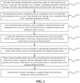
- FIG. 1 is a flowchart of a network delay in-band telemetry method according to an embodiment of the present invention. As shown in FIG. 1 , the method specifically includes the following operations.
- network-wide topology information is acquired by means of a link layer discovery protocol.
- a network-wide topology view is created.
- a mathematical model is built for a network-wide delay measurement problem based on the network-wide topology view.
- a network-wide link delay in-band telemetry simulation system is constructed based on an Open Network Operating System (ONOS) controller and a Mini Network Emulation (Mininet) simulation software platform, and a telemetry main program is deployed on a minimum vertex cover set by means of mounting a probe host.
- ONOS Open Network Operating System
- Mininet Mini Network Emulation
- a network-wide topology is modeled as a simple undirected connected graph.
- Network switch devices and terminals are vertices in the graph, and network links are undirected edges in the graph.
- Devices in the network that perform the network delay detection using probe packets are defined as probe devices.
- probe devices In in-band telemetry, it is necessary to select a portion of the devices as the probe devices, which correspond to a portion of vertices in the network.
- an edge in the network and its corresponding network link are mentioned, and when a device in the network and its corresponding node are mentioned, they would not be further distinguished from each other.
- In-band network telemetry is used to perform detection in the network.
- a forwarding path through which a probe packet passes is defined as a detection path.
- a number of edges of the detection path is defined as the length of the detection path. According to the definition of the detection path, both the starting vertices and the ending vertices of the detection path are probe devices.
- T i represents the time consumed to perform the in-band telemetry on the path path j in S by using the in-band network telemetry.
- the selection of S must ensure that the length of the detection path is not too large, so that T max is within a reasonable range to ensure the real-time performance and accuracy of the in-band telemetry.
- the overhead of the in-band telemetry is measured.
- the additional overhead required for the in-band telemetry is mainly divided into two parts: deployment overhead of the probe devices and additional overhead caused by repeated link measurements.
- deployment overhead of the probe devices is c
- S ⁇ path i
- i 1,2,..., l ⁇
- Cost deploy c ⁇ V 0
- Cost redundant ⁇ ⁇ d ⁇ E
- the mathematical model is simplified based on a minimum vertex cover algorithm, and a minimum vertex cover set of the network-wide topology view is estimated based on the simplified mathematical model.
- a minimum vertex cover algorithm based on the association degree may be used. Edges incident to vertices with high association degrees are preferentially selected for coverage, and a minimum vertex cover set V " of the network topology G ( V , E ) is estimated by means of multiple rounds of iterative addition.
- the above-mentioned network-wide delay in-band telemetry problem for modeling is a multi-objective combination optimization problem, in which three objectives mutually restrict each other. It is difficult to directly obtain an optimal solution to the above-mentioned combination optimization problem. Moreover, since the measurement of some indicators is affected by the subjective utility of the network managers in actual situations, obtaining the absolute optimal solution itself is not very meaningful. Therefore, in the embodiments of the present invention, the importance of the three objectives is comprehensively weighed up to make trade-offs among the objectives, and a satisfactory solution of the problem is obtained within a range in which each indicator can be tolerated.
- the time consumed by the in-band telemetry is directly related to the accuracy and availability of the measurement results, the time T max consumed by detecting the network-wide link delay once is the most important indicator, which needs to be ensured first.
- the key to ensure T max is to ensure that the maximum length of the detection path is relatively small.
- the overhead caused by the repeated link measurement is small. Therefore, it is necessary to optimize the deployment overhead of the probe devices, that is, optimizing the number of the deployed probe devices, while ensuring that the link repetition rate is within a reasonable range.
- the above-mentioned problem is transformed into solving a minimum point cover problem, and an optimal set of detection paths S is constructed.
- V" ⁇ V is a point cover of the graph G ( V , E)
- V" is a minimum point cover of the graph G ( V,E ) .
- the minimum vertex cover problem is one of Karp's famous 21 NP-complete problems.
- the algorithms that can ensure the efficiency of solving the minimum subversion problem are all heuristic algorithms. Next, some terms and symbols are explained before a heuristic algorithm of the present invention is described.
- E G ( V' ) represents a set of edges in the graph G associated with the vertices in V'.
- the heuristic algorithm based on association degree in an embodiment of the present invention is described.
- the minimum point cover algorithm based on association degree in each iteration, edges incident to vertices with a high association degree are preferentially selected for coverage, and it is ensured that no neighboring points in the same iteration are added to the point cover set.
- FIG. 2 A flowchart of a heuristic algorithm for finding a minimum vertex cover set is shown in FIG. 2 .
- a set of detection paths satisfying a preset condition is constructed based on the minimum vertex cover set, and a set of probe devices is deployed based on the minimum vertex cover set.
- V " is a minimum point cover set of the network G ( V , E ).
- An algorithm for constructing a detection path in S is as follows:
- FIG. 3 An algorithm flowchart for constructing a set S of detection paths according to the minimum vertex cover set is shown in FIG. 3 .
- the minimum nature of the minimum vertex cover set ensures the optimization of the number of deployed probe devices, thus reducing the deployment overhead Cost deploy of the probe devices.
- a respective probe host is mounted on each probe device in the set of probe devices, and a probe packet is sent along a detection path, which starts from the probe device, in the set of detection paths.
- the probe host is mounted on a network device in the probe device set. Each detection host is mounted to a respective probe device v ⁇ V .
- the probe packet is sent along a detection path starting from v in S by means of source routing.
- v k is also a probe device, and a probe packet generated by the detection host mounted to v is forwarded along the path v ⁇ v 1 ⁇ ... ⁇ v k -1 ⁇ v k by means of the source routing.
- Each probe device v provides a default route to forward all probe packets destined for v to a detection terminal suspended from v .
- all network forwarding devices are controlled to add multiple information fields to the probe packet during a process of sending and/or forwarding the probe packet.
- all network forwarding devices add information fields such as a packet arrival time, a receiving port, a packet sending time, a sending port, and a device number of the network forwarding devices themselves to the probe packet by means of a programmable switch.
- Any one probe device receives a probe packet destined for itself, extracts the information fields in the probe packet, and calculates a link delay of the probe packet path. Specifically, it is assumed that the arrival time of the probe packet marked at a certain hop v i is t i , the arrival time of the probe packet marked at a previous hop v i- 1 is t i -1 , and the sending time is t i ⁇ 1 ′ .
- the probe host reports the collected link delay information to a controller.
- network-wide link delay information is updated based on the link delay information of the each probe device.
- the controller acquires link delay reports regularly submitted by the probe devices, and updates and summarizes global network link delay information.
- the entire processing flow of the network-wide link delay in-band telemetry includes: acquiring network-wide topology information and building a problem model; simplifying the problem model and calculating a maximum vertex coverage V " ; constructing a set of detection paths S according to V " and generating a measurement policy; sending, by a probe device, a probe packet along a detection path; adding, by the forwarding device on each hop, measurement information to a probe packet header; receiving, by the probe device, the probe packet, calculating a packet path link delay and reporting the same to a controller; and collecting and summarizing delay reports by the controller, and completing measurements.
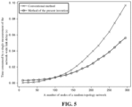
- FIG. 5 is a diagram of a relationship between a scale of a random topology graph and time required for network-wide link delay measurement. As the total number of random topology vertices increases, the time consumed by the method in the embodiment of the present invention to perform a single measurement of the network-wide link delay gradually increases. When the network scale further increases, the method of the embodiments of the present invention for performing a single measurement of the network-wide link delay is superior in time to the conventional methods for performing the measurements link-by-link using round-trip delay. As the network topology scale further increases, the advantages of the method in the embodiment of the present invention become more obvious.
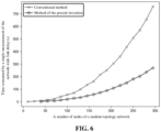
- FIG. 6 is a diagram of a relationship between a scale of a random topology graph and a network-wide link delay measurement overhead. Since the link repetition coverage rate of the method in the embodiment of the present invention is ⁇ ⁇ 1, and the link repetition coverage rate of conventional methods is equal to 1, the traffic overhead of the method of the embodiments of the present invention is always better than that of the conventional methods. In addition, the method of the embodiments of the present invention interacts less with the control plane, so that additional overhead of frequent interaction between the data plane and the control plane is less.
- the network-wide link delay can be quickly and accurately measured, the single network-wide link delay measurement is performed more quickly than the conventional methods, and the required traffic overhead is less than that of the conventional methods.
- a network delay in-band telemetry solution includes: acquiring network-wide topology information by means of a link layer discovery protocol, creating a network-wide topology view, and building, based on the network-wide topology view, a mathematical model for a network-wide delay measurement problem; simplifying the mathematical model based on a minimum vertex cover algorithm, and estimating a minimum vertex cover set of the network-wide topology view based on the simplified mathematical model; constructing, based on the minimum vertex cover set, a set of detection paths satisfying a preset condition, and deploying a set of probe devices based on the minimum vertex cover set; mounting a respective probe host on each probe device in the set of probe devices, and sending a probe packet along a detection path, which starts from the probe device, in the set of detection paths; controlling all network forwarding devices to add multiple information fields to the probe packet during a process of sending and/or forwarding the probe packet; when a respective probe packet received by each probe device and destined for the probe device itself
- the minimum vertex cover algorithm is used to optimize the deployment position of measurement terminals in the network and reconstruct the set of detection paths in the network, thereby planning a network measurement scheme for in-band telemetry and enhancing the real-time performance and accuracy of the network delay measurement.
- FIG. 7 is a structural diagram of a network delay in-band telemetry apparatus according to an embodiment of the present invention.
- the apparatus includes a building portion 701, a simplifying portion 702, a deployment portion 703, a detection portion 704, an adding portion 705, an acquisition portion 706 and an update module 707.
- the building portion 701 is configured to acquire network-wide topology information by means of a link layer discovery protocol, create a network-wide topology view, and build a mathematical model for a network-wide delay measurement problem based on the network-wide topology view.
- the simplifying portion 702 is configured to simplify the mathematical model based on a minimum vertex cover algorithm, and estimate a minimum vertex cover set of the network-wide topology view based on the simplified mathematical model.
- the deployment portion 703 is configured to construct a set of detection paths satisfying a preset condition based on the minimum vertex cover set, and deploy a set of probe devices based on the minimum vertex cover set.
- the detection portion 704 is configured to mount a respective probe host on each probe device in the set of probe devices, and send a probe packet along a detection path, which starts from the probe device, in the set of detection paths.
- the adding portion 705 is configured to control all network forwarding devices to add multiple information fields to the probe packet during a process of sending and/or forwarding the probe packet.
- the acquisition portion 706 is configured to, when a respective probe packet received by each probe device and destined for the probe device itself is acquired, extract multiple information fields in the probe packet, and calculate link delay information on a probe packet path based on the multiple information fields.
- the update portion 707 is configured to update network-wide link delay information based on the link delay information of the each probe device.
- the network delay in-band telemetry apparatus provided in the embodiments of the present invention is configured to perform the network delay in-band telemetry method provided in the foregoing embodiments.
- the implementation manner and principle thereof are the same as those in the foregoing embodiments. For details, reference can be made to relevant descriptions of the foregoing method embodiments, and would not be described herein again.
- the building portion 701 is further configured to: model a network-wide topology as a network-wide topology view, network switch devices and terminals being vertices in the view, and network links being undirected edges in the view; based on the network-wide topology view, detect all paths by using an in-band network telemetry method, and acquire timeliness and overhead for detecting all of the paths; and build the mathematical model for the network-wide delay measurement problem based on all of the paths, and the timeliness and overhead for detecting all of the paths.
- the simplifying portion 702 is further configured to: calculate association degrees of edges incident to each vertex based on the network-wide topology view, and select edges incident to vertices with association degrees greater than a preset threshold for coverage based on the minimum vertex cover algorithm; and recalculate the association degrees of uncovered edges incident to each vertex, repeat the operation of selecting the edges incident to the vertices with the association degrees greater than the preset threshold for coverage based on the minimum vertex cover algorithm until all edges in the graph are covered, and obtaining the minimum vertex cover set of the network-wide topology view.
- the detection portion 704 is further configured to: send, by the probe host by means of source routing, the probe packet along the detection path, which starts from the probe device, in the minimum vertex cover set; and acquire a respective probe packet destined for each probe device and forwarding same to a respective detection terminal suspended from each probe device.
- the acquisition portion 706 is further configured to: take a difference between an arrival time of a probe packet marked at a first probe device of a certain hop and an arrival time of a probe packet marked at a second probe device of a previous hop as a link delay between the first probe device and the second probe device; and take a difference between the arrival time of the probe packet marked at the first probe device of the certain hop and a sending time of the probe packet marked at the second probe device of the previous hop as a propagation delay of a link between the first probe device and the second probe device.
- the update portion 707 is further configured to: regularly acquire link delay information reported by each probe device, and update the network-wide link delay information based on the reported link delay information.
- the acquisition portion 706 is further configured to: add the multiple information fields to the probe packet by means of a programmable switch.
- the multiple information fields at least include a packet arrival time, a receiving port, a packet sending time, a sending port, and an own device number.
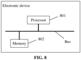
- FIG. 8 shows an electronic device according to an embodiment of the present invention.
- the electronic device includes a processor 801 and a memory 802.
- the processor 801 and the memory 802 may be connected by means of a bus or in another manner.
- the connection by means of a bus is used as an example.
- the processor 801 may be a Central Processing Unit (CPU).
- the processor 801 may also be another general-purpose processor, a Digital Signal Processor (DSP), an Application-Specific Integrated Circuit (ASIC), a Field-Programmable Gate Array (FPGA) or another programmable logic device, a discrete gate or transistor logic device, a discrete hardware component or another chip, or a combination of the above types of chips.
- DSP Digital Signal Processor
- ASIC Application-Specific Integrated Circuit
- FPGA Field-Programmable Gate Array
- the memory 802 is a non-transitory computer-readable storage medium, which may be used to store a non-transitory software program, a non-transitory computer-executable program and module, such as program instructions/modules corresponding to the methods provided in the embodiments of the present invention.
- the processor 801 executes various functional applications of the processor and data processing by running the non-transitory software program, instructions and modules stored in the memory 802. That is, the processor 801 implements the methods in the above method embodiments.
- the memory 802 may include a stored program area and a stored data area.
- the stored program area may store an operating system and an application program required for at least one function.
- the stored data area may store data created by the processor 801 and the like.
- the memory 802 may include a high-speed random access memory and may also include a non-transitory memory, such as at least one magnetic disk storage device, a flash memory device or other non-transitory solid-state memory devices.
- the memory 802 may optionally include a memory arranged remotely from the processor 801, and such a remote memory may be connected to the processor 801 by means of a network. Examples of the above network may include, but are not limited to, the Internet, an intranet, a local area network, a mobile communication network and combinations thereof.
- One or more modules are stored in the memory 802, and when executed by the processor 801, the modules perform the methods in the foregoing method embodiments.
- the program may be stored in a computer-readable storage medium.
- the storage medium may be a magnetic disk, an optical disk, a read-only memory (ROM), a random access memory (RAM), a flash memory, a hard disk drive (HDD), a solid-state drive (SSD) or the like.
- the storage medium may also include a combination of the above types of memories.
- the present invention provides a network delay in-band telemetry method and apparatus, an electronic device, and a storage medium.
- the method includes: acquiring network-wide topology information by means of a link layer discovery protocol, creating a network-wide topology view, and building, based on the network-wide topology view, a mathematical model for a network-wide delay measurement problem; simplifying the mathematical model based on a minimum vertex cover algorithm, and estimating a minimum vertex cover set of the network-wide topology view based on the simplified mathematical model; constructing, based on the minimum vertex cover set, a set of detection paths satisfying a preset condition, and deploying a set of probe devices based on the minimum vertex cover set; mounting a respective probe host on each probe device in the set of probe devices, and sending a probe packet along a detection path, which starts from the probe device, in the set of detection paths; controlling all network forwarding devices to add multiple information fields to the probe packet during a process of sending and/or forwarding the probe packet; when a respective
- the minimum vertex cover algorithm is used to optimize the deployment position of measurement terminals in the network and reconstruct the set of detection paths in the network, thereby planning a network measurement scheme for in-band telemetry and enhancing the real-time performance and accuracy of the network delay measurement.
Landscapes
- Engineering & Computer Science (AREA)
- Computer Networks & Wireless Communication (AREA)
- Signal Processing (AREA)
- Environmental & Geological Engineering (AREA)
- Human Computer Interaction (AREA)
- Data Exchanges In Wide-Area Networks (AREA)
Abstract
Description
- The present application is based on and claims priority to the
Chinese Patent Application NO. 202310500422.4, filed on May 6, 2023 - Embodiments of the present invention relate to the field of network delay measurement, and in particular to a network delay in-band telemetry method and apparatus, an electronic device and a storage medium.
- With the rapid development of Internet, a number of Internet users around the world continues increasing. With the rapid increase of the users and the increasing demand from the users, data traffic of the Internet is growing rapidly. The enormous volume, complicated devices and diverse protocols have made the Internet bloated and huge. The control logic and data plane of the conventional Internet are tightly coupled under distributed architecture, which has brought huge challenges to network development and management personnel of the Internet, making network transmission and network configuration optimization more difficult. Network transmission management is closely related to the prompt sensing and accurate measurement of network status. With the increase in traffic and the complexity of the network structure configuration, due to the distributed architecture of conventional Internet networks and the tight coupling of conventional switch hardware and control logic, it becomes increasingly difficult to acquire network status using conventional network measurement methods. Therefore, it is of great significance to develop an efficient and accurate network telemetry technology.
- In recent years, Software Defined Networking (SDN) and Programmable Data Plane (PDP) technology have developed rapidly and become new technical supports for the network telemetry technology. SDN architecture separates a control plane and a data plane that are tightly coupled to network devices in conventional networks, and elevates the control plane to a network controller. A switch device in the network only retains the data plane, and the control plane sends a flow table rule to a data plane switch by means of an Openflow protocol to complete the control of the data plane. The PDP technology provides data plane programmability for the users, and a programmable switch allows processing network data packets by means of programming during the data packet transmission. The SDN architecture overcomes the rigidification caused by the tight coupling of conventional network control and forwarding, and provides a global view and centralized management of the networks by means of centralized control, whereas the PDP technology frees up hardware devices of the data plane, provides a protocol-independent forwarding system, and releases powerful processing capabilities on the data plane. The combination of the SDN architecture and the PDP technology provides more flexibility for large-scale network status telemetry technology.
- In-band Network Telemetry (INT) technology makes full use of the SDN technology and the PDP technology. In the forwarding process of the data packet, the data packet carries corresponding network device parameters at each hop of the forwarding path, the parameters carried by the data packet are extracted at a receiving terminal, and network status information on the forwarding path is calculated and submitted to a network controller. The network delay, which is one of the most important indicators in network status information, requires accurate INT measurement. How to deploy the INT to accomplish the accurate measurement of the global network delay is an urgent problem to be solved.
- In view of this, in order to solve the above technical problems or some of the technical problems, embodiments of the present invention provide a network delay in-band telemetry method and apparatus, an electronic device and a storage medium.
- In a first aspect, an embodiment of the present invention provides a network delay in-band telemetry method, which includes the following operations.
- Network-wide topology information is acquired by means of a link layer discovery protocol. A network-wide topology view is created. A mathematical model is built for a network-wide delay measurement problem based on the network-wide topology view.
- The mathematical model is simplified based on a minimum vertex cover algorithm, and a minimum vertex cover set of the network-wide topology view is estimated based on the simplified mathematical model.
- A set of detection paths satisfying a preset condition is constructed based on the minimum vertex cover set, and a set of probe devices is deployed based on the minimum vertex cover set.
- A respective probe host is mounted on each probe device in the set of probe devices, and a probe packet is sent along a detection path, which starts from the probe device, in the set of detection paths.
- All network forwarding devices are controlled to add multiple information fields to the probe packet during a process of sending and/or forwarding the probe packet.
- When a respective probe packet received by each probe device and destined for the probe device itself is acquired, multiple information fields in the probe packet are acquired, and link delay information on a probe packet path is calculated based on the multiple information fields.
- Network-wide link delay information is updated based on the link delay information of the each probe device.
- In a possible implementation, the method further includes the following operations.
- A network-wide topology is modeled as a network-wide topology view. Network switch devices and terminals are vertices in the view, and network links are undirected edges in the view.
- Based on the network-wide topology view, all paths are detected by using an in-band network telemetry method, and timeliness and overhead for detecting all of the paths are acquired.
- The mathematical model for the network-wide delay measurement problem is built based on all of the paths, and the timeliness and overhead for detecting all of the paths.
- In a possible implementation, the method further includes the following operations.
- Association degrees of edges incident to each vertex are calculated based on the network-wide topology view, and edges incident to vertices with association degrees greater than a preset threshold are selected based on the minimum vertex cover algorithm for coverage.
- The association degrees of uncovered edges incident to each vertex are recalculated. The operation that the edges incident to the vertices with association degrees greater than the preset threshold are selected based on the minimum vertex cover algorithm for coverage is repeated until all edges in the graph are covered. The minimum vertex cover set of the network-wide topology view are obtained.
- In a possible implementation, the method further includes the following operations.
- The probe host sends the probe packet along the detection path, which starts from the probe device, in the minimum vertex cover set by means of source routing.
- A respective probe packet destined for each probe device is acquired and the probe packet is forwarded to a detection terminal suspended from the probe device.
- In a possible implementation, the method further includes the following operations.
- A difference between an arrival time of a probe packet marked at a first probe device of a certain hop and an arrival time of a probe packet marked at a second probe device of a previous hop is taken as a link delay between the first probe device and the second probe device.
- A difference between the arrival time of the probe packet marked at the first probe device of the certain hop and a sending time of the probe packet marked at the second probe device of the previous hop is taken as a propagation delay of a link between the first probe device and the second probe device.
- In a possible implementation, the method further includes the following operations.
- Link delay information reported by each probe device is regularly acquired, and the network-wide link delay information is updated based on the reported link delay information.
- In a possible implementation, the method further includes the following operations.
- The multiple information fields are added to the probe packet by means of a programmable switch. The multiple information fields at least include a packet arrival time, a receiving port, a packet sending time, a sending port, and an own device number.
- In a second aspect, an embodiment of the present invention provides a network delay in-band telemetry apparatus. The network delay in-band telemetry apparatus includes a building portion, a simplifying portion, a deployment portion, a detection portion, an adding portion, an acquisition portion and an update module.
- The building portion is configured to acquire network-wide topology information by means of a link layer discovery protocol, create a network-wide topology view, and build a mathematical model for a network-wide delay measurement problem based on the network-wide topology view.
- The simplifying portion is configured to simplify the mathematical model based on a minimum vertex cover algorithm, and estimate a minimum vertex cover set of the network-wide topology view based on the simplified mathematical model.
- The deployment portion is configured to construct a set of detection paths satisfying a preset condition based on the minimum vertex cover set, and deploy a set of probe devices based on the minimum vertex cover set.
- The detection portion is configured to mount a respective probe host on each probe device in the set of probe devices, and send a probe packet along a detection path, which starts from the probe device, in the set of detection paths.
- The adding portion is configured to control all network forwarding devices to add multiple information fields to the probe packet during a process of sending and/or forwarding the probe packet.
- The acquisition portion is configured to, when a respective probe packet received by each probe device and destined for the probe device itself is acquired, extract multiple information fields in the probe packet, and calculate link delay information on a probe packet path based on the multiple information fields.
- The update portion is configured to update network-wide link delay information based on the link delay information of the each probe device.
- In a third aspect, an embodiment of the present invention provides an electronic device which includes a processor and a memory. The processor is configured to execute a network delay in-band telemetry program stored in the memory to implement the network delay in-band telemetry method described above in the first aspect.
- In a fourth aspect, an embodiment of the present invention provides a storage medium having stored thereon one or more programs executable by one or more processors for implementing the network delay in-band telemetry method described above in the first aspect.
- A network delay in-band telemetry solution provided in embodiments of the present invention includes: acquiring network-wide topology information by means of a link layer discovery protocol, creating a network-wide topology view, and building, based on the network-wide topology view, a mathematical model for a network-wide delay measurement problem; simplifying the mathematical model based on a minimum vertex cover algorithm, and estimating a minimum vertex cover set of the network-wide topology view based on the simplified mathematical model; constructing, based on the minimum vertex cover set, a set of detection paths satisfying a preset condition, and deploying a set of probe devices based on the minimum vertex cover set; mounting a respective probe host on each probe device in the set of probe devices, and sending a probe packet along a detection path, which starts from the probe device, in the set of detection paths; controlling all network forwarding devices to add multiple information fields to the probe packet during a process of sending and/or forwarding the probe packet; when a respective probe packet received by each probe device and destined for the probe device itself is acquired, extracting multiple information fields in the probe packet, and calculating link delay information on a probe packet path based on the multiple information fields; and updating network-wide link delay information based on the link delay information of the each probe device. In the present solution, the minimum vertex cover algorithm is used to optimize the deployment position of measurement terminals in the network and reconstruct the set of detection paths in the network, thereby planning a network measurement scheme for in-band telemetry and enhancing the real-time performance and accuracy of the network delay measurement.
-
-
FIG. 1 is a flowchart of a network delay in-band telemetry method according to an embodiment of the present invention. -
FIG. 2 is a flowchart of a heuristic algorithm for finding a minimum vertex cover set according to an embodiment of the present invention. -
FIG. 3 is an algorithm flowchart for constructing a set of detection paths according to an embodiment of the present invention. -
FIG. 4 is a flowchart of a network-wide link delay measurement process according to an embodiment of the present invention. -
FIG. 5 is a diagram of a relationship between a scale of a random topology graph and time required for network-wide link delay measurement according to an embodiment of the present invention. -
FIG. 6 is a diagram of a relationship between a scale of a random topology graph and network-wide link delay measurement overhead according to an embodiment of the present invention. -
FIG. 7 is a structural diagram of a network delay in-band telemetry apparatus according to an embodiment of the present invention. -
FIG. 8 is a structural diagram of an electronic device according to an embodiment of the present invention. - In order to make the objectives, technical solutions and advantages of the embodiments of the present invention clearer, the technical solutions in the embodiments of the present invention would be clearly and completely described below with reference to the accompanying drawings in the embodiments of the present invention. Obviously, the described embodiments are some of the embodiments of the present invention, rather than all of the embodiments. All other embodiments obtained by those skilled in the art based on the embodiments of the present invention without creative efforts fall within the scope of protection of the present invention.
- To facilitate understanding of the embodiments of the present invention, specific embodiments would be further illustrated and described below with reference to the accompanying drawings, which do not constitute a limitation on the embodiments of the present invention.
-
FIG. 1 is a flowchart of a network delay in-band telemetry method according to an embodiment of the present invention. As shown inFIG. 1 , the method specifically includes the following operations. - At S11, network-wide topology information is acquired by means of a link layer discovery protocol. A network-wide topology view is created. A mathematical model is built for a network-wide delay measurement problem based on the network-wide topology view.
- In the embodiment of the present invention, a network-wide link delay in-band telemetry simulation system is constructed based on an Open Network Operating System (ONOS) controller and a Mini Network Emulation (Mininet) simulation software platform, and a telemetry main program is deployed on a minimum vertex cover set by means of mounting a probe host.
- Specifically, a network-wide topology is modeled as a simple undirected connected graph. Network switch devices and terminals are vertices in the graph, and network links are undirected edges in the graph. Devices in the network that perform the network delay detection using probe packets are defined as probe devices. In in-band telemetry, it is necessary to select a portion of the devices as the probe devices, which correspond to a portion of vertices in the network. Furthermore, when an edge in the network and its corresponding network link are mentioned, and when a device in the network and its corresponding node are mentioned, they would not be further distinguished from each other.
- The network is modeled as a simple undirected graph G(V, E), where V ={v 1, v 2, ..., vn } is a set of vertices in the graph, and E = {e 1, e 2,...,em } is a set of edges of the graph. In-band network telemetry is used to perform detection in the network. A forwarding path through which a probe packet passes is defined as a detection path. A detection path may be represented as a path path = {v 0, e 0, v 1, e 1, ..., v k-1, e k-1, vk } in a network graph model, herein two endpoints of ei are vi and v i+1, respectively, and i ∈ {0,1,2,..., k -1} . A number of edges of the detection path is defined as the length of the detection path. According to the definition of the detection path, both the starting vertices and the ending vertices of the detection path are probe devices. Some symbols and terms would be introduced below, and a network-wide delay in-band telemetry problem is modeled.
- For an edge ei in a network, if ei ∈ path, it is said that the detection path path covers ei . ei being covered by path means that the detection of path would obtain the relevant parameters of ei . To measure the delay of each link in the entire network, it is necessary to find a set of detection paths S = {pathi | i = 1,2,...,l} in the network so that each edge in the network is covered by a detection path in S. That is, ∀ei ∈ E, ∃pathj ∈ S , so that pathj covers ei .
- Firstly, the timeliness of in-band telemetry is measured. Taking that the propagation delay of edge eα is τα, and that the queuing and processing delay at node vα is κα , since probe traffic is tiny, the sending delay is ignored, and the time required to perform delay detection on the path pathi ={v 0, e 0, ..., v k-1, e k-1, vk } once by using the in-band network telemetry is:

where τα, κα > 0. Hence, there is a significant negative correlation between the real-time performance of the in-band telemetry and the length of the detection path. - For the selection of S ={pathi |i = 1,2,...,l}, the detection on all detection paths is performed in parallel, and the time required for detecting the network-wide link delay once is:

where Ti represents the time consumed to perform the in-band telemetry on the path pathj in S by using the in-band network telemetry. The selection of S must ensure that the length of the detection path is not too large, so that T max is within a reasonable range to ensure the real-time performance and accuracy of the in-band telemetry. - Secondly, the overhead of the in-band telemetry is measured. The additional overhead required for the in-band telemetry is mainly divided into two parts: deployment overhead of the probe devices and additional overhead caused by repeated link measurements. Assuming that the average deployment overhead of the probe devices is c , S = {pathi | i = 1,2,...,l} is selected, and V 0 is taken as a set of probe devices that need to be deployed, that is:

- Then, the total overhead of deploying the probe devices is proportional to the total number of the deployed probe devices:

- Taking the average overhead of transmitting a single probe packet on an edge as d, and taking m 0 as the sum of path lengths in S, that is:

- Then, the link repetition rate is:

- Then, the total overhead of the repeated link detection is:

- In actual situations, since the probe traffic is tiny and d is usually relatively small, when the link repetition rate λ is not very large, the overhead caused by the repeated link measurements is often smaller than the deployment overhead of the probe devices.
- In summary, the network-wide delay in-band telemetry problem can be described abstractly as: finding a set of detection paths S = {pathi | i = 1, 2, ...,l}, so that for ∀ei ∈E , ∃pathj e S, pathj would cover ei , and the following indicators are minimized:



- At S12, the mathematical model is simplified based on a minimum vertex cover algorithm, and a minimum vertex cover set of the network-wide topology view is estimated based on the simplified mathematical model.
- In order to simplify the mathematical model of the network-wide delay in-band telemetry problem, a minimum vertex cover algorithm based on the association degree may be used. Edges incident to vertices with high association degrees are preferentially selected for coverage, and a minimum vertex cover set V" of the network topology G(V , E) is estimated by means of multiple rounds of iterative addition.
- Specifically, the above-mentioned network-wide delay in-band telemetry problem for modeling is a multi-objective combination optimization problem, in which three objectives mutually restrict each other. It is difficult to directly obtain an optimal solution to the above-mentioned combination optimization problem. Moreover, since the measurement of some indicators is affected by the subjective utility of the network managers in actual situations, obtaining the absolute optimal solution itself is not very meaningful. Therefore, in the embodiments of the present invention, the importance of the three objectives is comprehensively weighed up to make trade-offs among the objectives, and a satisfactory solution of the problem is obtained within a range in which each indicator can be tolerated.
- Since the time consumed by the in-band telemetry is directly related to the accuracy and availability of the measurement results, the time T max consumed by detecting the network-wide link delay once is the most important indicator, which needs to be ensured first. The key to ensure T max is to ensure that the maximum length of the detection path is relatively small. Secondly, due to the tiny probe traffic in actual situations, when the repetition rate of link coverage is not very large, the overhead caused by the repeated link measurement is small. Therefore, it is necessary to optimize the deployment overhead of the probe devices, that is, optimizing the number of the deployed probe devices, while ensuring that the link repetition rate is within a reasonable range. In summary, in the embodiments of the present invention, the above-mentioned problem is transformed into solving a minimum point cover problem, and an optimal set of detection paths S is constructed.
- For a vertex v and an edge e in an undirected graph G(V , E), if e is associated with v, it is said that the edge e is covered by the vertex v . For a vertex set V' ⊆ V, if for ∀e ∈ E, ∃v ∈ V', the edge e is covered by the vertex v, it is said that V' is a point cover of the graph G(V , E) . If V" ⊆ V is a point cover of the graph G(V , E), and for any one point cover V" ⊆ V of G(V , E), there is |V"|≤|V'|, V" is a minimum point cover of the graph G(V,E). For general graphs, there is no efficient algorithm that can obtain an optimal solution to the minimum point cover problem. In fact, the minimum vertex cover problem is one of Karp's famous 21 NP-complete problems. Currently, the algorithms that can ensure the efficiency of solving the minimum subversion problem are all heuristic algorithms. Next, some terms and symbols are explained before a heuristic algorithm of the present invention is described.
- For an undirected graph G(V , E), E(G) represents a set of edges of the graph G, that is, E(G) == E. V(G) represents a set of vertices of the graph G, that is, V(G) == V . Taking V' ⊆V as a set of points in the graph G, EG (V') represents a set of edges in the graph G associated with the vertices in V'. G - V' represents a graph obtained after removing vertices in V' and edges in EG (V') from the graph G , that is, G-V'=(V-V',E-EG (V')). Assuming that path = {v 0 e 0 v 1...v k-1 e k-1 vk } is a path in the graph G, G - path represents a graph obtained by removing the edges in path from the graph G, that is, G - path == (V , E -E(path)).
- For an edge e = (v 0, v 1) in the undirected graph G(V , E), if v 0 ≠v 1, it is said that vertex v 0 is adjacent to vertex v 1. For vertex v ∈ V, a set of points adjacent to v in V is referred to as a domain of vertex v in the graph G, recorded as NG (v), that is:

- For vertex v ∈ V in the undirected graph G(V , E), the association degree of v is defined as the sum of the degrees of all points adjacent to v, plus the degree of v itself, and the association degree of v is recorded as D(v), then

- Further, the heuristic algorithm based on association degree in an embodiment of the present invention is described. In the minimum point cover algorithm based on association degree, in each iteration, edges incident to vertices with a high association degree are preferentially selected for coverage, and it is ensured that no neighboring points in the same iteration are added to the point cover set. At the end of each iteration, the covered edges are removed from the graph and the association degree is recalculated for the next iteration until all edges in the graph are covered, and a vertex cover set is outputted. Steps of the minimum point cover algorithm based on association degree are as follows:
- 1) Initializing the graph G' = G, V" = ∅, and a vertex access flag: initializing the graph G' =G , initializing the vertex cover set V" = ∅ , and initializing the access flag visited(w) = false, ∀w ∈ V(G') for each vertex.
- 2) If E(G') == ∅, the algorithm ends, and the vertex cover set V" is outputted.
- 3) Otherwise, recalculating the association degree D(w), ∀w ∈ V(G') of vertices in G'.
- 4) Deleting vertices with the association degrees of 0 from the graph G', that is, G' = G' - {w ∈ V(G')| D(w) == 0} .
- 5) Selecting an unaccessed vertex v with the greatest association degree in G', and accessing v : V" = {v} ∪V" . Selecting v ∈ V(G') , visited(v) == false, s.t.

- 6) Accessing the domain of v : For ∀w ∈ NG' (v), setting visited(w)= true .
- 7) Delete the vertex v from G': G' = G' - {v}.
- 8) Does an unaccessed vertex exist in G' ?
If {w ∈ V(G') | visited(w) == false} ≠ ∅, go to 4). - 9) Resetting access flags for all nodes in G': visited(w) = false, ∀w ∈ V(G'). Go to 2).
- A flowchart of a heuristic algorithm for finding a minimum vertex cover set is shown in
FIG. 2 . - At S13, a set of detection paths satisfying a preset condition is constructed based on the minimum vertex cover set, and a set of probe devices is deployed based on the minimum vertex cover set.
- According to the minimum vertex cover set V" of the network topology G(V, E), an optimal set of detection paths S is constructed. It has been found that V" is a minimum point cover set of the network G(V , E). An algorithm for constructing a detection path in S is as follows:
- 1) Initializing a graph G' = G, and initializing S = ∅.
- 2) If E(G') == ∅, the algorithm ends.
- 3) Otherwise, arbitrarily taking an edge e 0=(v 0, v1) in E(G') , where v0 ∈ V" .
Taking ∀e 0 ∈ E(G'), according to the definition of the minimum vertex cover set, a certain endpoint of e 0 is v 0 ∈ V", and the other endpoint of e 0 is recorded as v 1. - 4) If v 1 ∈ V", taking path = v 0 e 0 v 1, and go to 7).
- 5) Otherwise, if deg(v¡) = 1, taking path = v 0 e 0 v 1 e 0 v 0, and go to 7).
- 6) Otherwise, arbitrarily taking an edge e 1=(v1, v2) connected to v 1, where v1 ≠ v2, and taking path = v 0 e 0 v 1 e 1 v 2 .
Arbitrarily taking an edge e 1(e 1 ≠ e 0) connected to v 1, and according to the definition of the minimum vertex cover set, e 1 is covered by a certain vertex v 2 in V". Since v 1 ∉ V", v 2 ≠ v 1. Taking path = v 0 e 0 v 1 e 1 v 2. - 7) Taking S = S ∪ {path} and G' = G' - path, and go to 2).
- In summary, an algorithm flowchart for constructing a set S of detection paths according to the minimum vertex cover set is shown in
FIG. 3 . - Excellent properties of the optimal set S of the detection paths as constructed above would be described below. First of all, for any detection path path ∈ S , length(path) ≤ 2. Therefore, the maximum path length in S is ≤ 2, the time T max consumed by detecting the network-wide link delay once is small, and the measurement accuracy is high. Secondly, the link repetition rate of the detection path path is λpath ≤ 1, and there is no link overlap for different detection paths, so that the global link repetition rate is λ <_ 1. Since the probe traffic is tiny, d is usually small, the additional overhead Costredundant ≤ d×|E| of repeated link detection is small. Finally, since the set V 0 of probe devices that need to be deployed is exactly the minimum vertex cover set V", on the premise of first ensuring that the objective T max is optimized and maintaining a small link repetition rate, the minimum nature of the minimum vertex cover set ensures the optimization of the number of deployed probe devices, thus reducing the deployment overhead Costdeploy of the probe devices.
- At S14, a respective probe host is mounted on each probe device in the set of probe devices, and a probe packet is sent along a detection path, which starts from the probe device, in the set of detection paths.
- The probe host is mounted on a network device in the probe device set. Each detection host is mounted to a respective probe device v ∈ V . The probe packet is sent along a detection path starting from v in S by means of source routing. For each detection path path = v e 0...v k-1 e k-1 vk in S, as defined by the detection path, vk is also a probe device, and a probe packet generated by the detection host mounted to v is forwarded along the path v →v 1 →... →v k-1 →vk by means of the source routing. Each probe device v provides a default route to forward all probe packets destined for v to a detection terminal suspended from v.
- At S15, all network forwarding devices are controlled to add multiple information fields to the probe packet during a process of sending and/or forwarding the probe packet.
- In an embodiment of the present invention, during the process of sending and/or forwarding the probe packet, all network forwarding devices add information fields such as a packet arrival time, a receiving port, a packet sending time, a sending port, and a device number of the network forwarding devices themselves to the probe packet by means of a programmable switch.
- At S16, when a respective probe packet received by each probe device and destined for the probe device itself is acquired, multiple information fields in the probe packet are acquired, and link delay information on a probe packet path is calculated based on the multiple information fields.
- Any one probe device receives a probe packet destined for itself, extracts the information fields in the probe packet, and calculates a link delay of the probe packet path. Specifically, it is assumed that the arrival time of the probe packet marked at a certain hop vi is ti , the arrival time of the probe packet marked at a previous hop v i-1 is t i-1, and the sending time is


- At
S 17, network-wide link delay information is updated based on the link delay information of the each probe device. - The controller acquires link delay reports regularly submitted by the probe devices, and updates and summarizes global network link delay information.
- To summarize all of the above steps, the entire processing flow of network-wide link delay in-band telemetry is shown in
FIG. 4 . The entire processing flow of the network-wide link delay in-band telemetry includes: acquiring network-wide topology information and building a problem model; simplifying the problem model and calculating a maximum vertex coverage V" ; constructing a set of detection paths S according to V" and generating a measurement policy; sending, by a probe device, a probe packet along a detection path; adding, by the forwarding device on each hop, measurement information to a probe packet header; receiving, by the probe device, the probe packet, calculating a packet path link delay and reporting the same to a controller; and collecting and summarizing delay reports by the controller, and completing measurements. -
FIG. 5 is a diagram of a relationship between a scale of a random topology graph and time required for network-wide link delay measurement. As the total number of random topology vertices increases, the time consumed by the method in the embodiment of the present invention to perform a single measurement of the network-wide link delay gradually increases. When the network scale further increases, the method of the embodiments of the present invention for performing a single measurement of the network-wide link delay is superior in time to the conventional methods for performing the measurements link-by-link using round-trip delay. As the network topology scale further increases, the advantages of the method in the embodiment of the present invention become more obvious. -
FIG. 6 is a diagram of a relationship between a scale of a random topology graph and a network-wide link delay measurement overhead. Since the link repetition coverage rate of the method in the embodiment of the present invention is λ ≤ 1, and the link repetition coverage rate of conventional methods is equal to 1, the traffic overhead of the method of the embodiments of the present invention is always better than that of the conventional methods. In addition, the method of the embodiments of the present invention interacts less with the control plane, so that additional overhead of frequent interaction between the data plane and the control plane is less. - By comparing the relationship between the measurement delay and the measurement overhead, according to the embodiments of the present invention, the network-wide link delay can be quickly and accurately measured, the single network-wide link delay measurement is performed more quickly than the conventional methods, and the required traffic overhead is less than that of the conventional methods.
- A network delay in-band telemetry solution provided in embodiments of the present invention includes: acquiring network-wide topology information by means of a link layer discovery protocol, creating a network-wide topology view, and building, based on the network-wide topology view, a mathematical model for a network-wide delay measurement problem; simplifying the mathematical model based on a minimum vertex cover algorithm, and estimating a minimum vertex cover set of the network-wide topology view based on the simplified mathematical model; constructing, based on the minimum vertex cover set, a set of detection paths satisfying a preset condition, and deploying a set of probe devices based on the minimum vertex cover set; mounting a respective probe host on each probe device in the set of probe devices, and sending a probe packet along a detection path, which starts from the probe device, in the set of detection paths; controlling all network forwarding devices to add multiple information fields to the probe packet during a process of sending and/or forwarding the probe packet; when a respective probe packet received by each probe device and destined for the probe device itself is acquired, extracting multiple information fields in the probe packet, and calculating link delay information on a probe packet path based on the multiple information fields; and updating network-wide link delay information based on the link delay information of the each probe device. In the present solution, the minimum vertex cover algorithm is used to optimize the deployment position of measurement terminals in the network and reconstruct the set of detection paths in the network, thereby planning a network measurement scheme for in-band telemetry and enhancing the real-time performance and accuracy of the network delay measurement.
-
FIG. 7 is a structural diagram of a network delay in-band telemetry apparatus according to an embodiment of the present invention. As shown inFIG. 7 , the apparatus includes abuilding portion 701, a simplifyingportion 702, adeployment portion 703, adetection portion 704, an addingportion 705, anacquisition portion 706 and anupdate module 707. - The
building portion 701 is configured to acquire network-wide topology information by means of a link layer discovery protocol, create a network-wide topology view, and build a mathematical model for a network-wide delay measurement problem based on the network-wide topology view. For a detailed description, reference is made to related descriptions corresponding to the foregoing method embodiments, and details are not described herein again. - The simplifying
portion 702 is configured to simplify the mathematical model based on a minimum vertex cover algorithm, and estimate a minimum vertex cover set of the network-wide topology view based on the simplified mathematical model. For a detailed description, reference is made to related descriptions corresponding to the foregoing method embodiments, and details are not described herein again. - The
deployment portion 703 is configured to construct a set of detection paths satisfying a preset condition based on the minimum vertex cover set, and deploy a set of probe devices based on the minimum vertex cover set. For a detailed description, reference is made to related descriptions corresponding to the foregoing method embodiments, and details are not described herein again. - The
detection portion 704 is configured to mount a respective probe host on each probe device in the set of probe devices, and send a probe packet along a detection path, which starts from the probe device, in the set of detection paths. For a detailed description, reference is made to related descriptions corresponding to the foregoing method embodiments, and details are not described herein again. - The adding
portion 705 is configured to control all network forwarding devices to add multiple information fields to the probe packet during a process of sending and/or forwarding the probe packet. For a detailed description, reference is made to related descriptions corresponding to the foregoing method embodiments, and details are not described herein again. - The
acquisition portion 706 is configured to, when a respective probe packet received by each probe device and destined for the probe device itself is acquired, extract multiple information fields in the probe packet, and calculate link delay information on a probe packet path based on the multiple information fields. For a detailed description, reference is made to related descriptions corresponding to the foregoing method embodiments, and details are not described herein again. - The
update portion 707 is configured to update network-wide link delay information based on the link delay information of the each probe device. For a detailed description, reference is made to related descriptions corresponding to the foregoing method embodiments, and details are not described herein again. - The network delay in-band telemetry apparatus provided in the embodiments of the present invention is configured to perform the network delay in-band telemetry method provided in the foregoing embodiments. The implementation manner and principle thereof are the same as those in the foregoing embodiments. For details, reference can be made to relevant descriptions of the foregoing method embodiments, and would not be described herein again.
- In some embodiments, the
building portion 701 is further configured to: model a network-wide topology as a network-wide topology view, network switch devices and terminals being vertices in the view, and network links being undirected edges in the view; based on the network-wide topology view, detect all paths by using an in-band network telemetry method, and acquire timeliness and overhead for detecting all of the paths; and build the mathematical model for the network-wide delay measurement problem based on all of the paths, and the timeliness and overhead for detecting all of the paths. - In some embodiments, the simplifying
portion 702 is further configured to: calculate association degrees of edges incident to each vertex based on the network-wide topology view, and select edges incident to vertices with association degrees greater than a preset threshold for coverage based on the minimum vertex cover algorithm; and recalculate the association degrees of uncovered edges incident to each vertex, repeat the operation of selecting the edges incident to the vertices with the association degrees greater than the preset threshold for coverage based on the minimum vertex cover algorithm until all edges in the graph are covered, and obtaining the minimum vertex cover set of the network-wide topology view. - In some embodiments, the
detection portion 704 is further configured to: send, by the probe host by means of source routing, the probe packet along the detection path, which starts from the probe device, in the minimum vertex cover set; and acquire a respective probe packet destined for each probe device and forwarding same to a respective detection terminal suspended from each probe device. - In some embodiments, the
acquisition portion 706 is further configured to: take a difference between an arrival time of a probe packet marked at a first probe device of a certain hop and an arrival time of a probe packet marked at a second probe device of a previous hop as a link delay between the first probe device and the second probe device; and take a difference between the arrival time of the probe packet marked at the first probe device of the certain hop and a sending time of the probe packet marked at the second probe device of the previous hop as a propagation delay of a link between the first probe device and the second probe device. - In some embodiments, the
update portion 707 is further configured to: regularly acquire link delay information reported by each probe device, and update the network-wide link delay information based on the reported link delay information. - In some embodiments, the
acquisition portion 706 is further configured to: add the multiple information fields to the probe packet by means of a programmable switch. The multiple information fields at least include a packet arrival time, a receiving port, a packet sending time, a sending port, and an own device number. -
FIG. 8 shows an electronic device according to an embodiment of the present invention. As shown inFIG. 8 , the electronic device includes aprocessor 801 and amemory 802. Theprocessor 801 and thememory 802 may be connected by means of a bus or in another manner. InFIG. 8 , the connection by means of a bus is used as an example. - The
processor 801 may be a Central Processing Unit (CPU). Theprocessor 801 may also be another general-purpose processor, a Digital Signal Processor (DSP), an Application-Specific Integrated Circuit (ASIC), a Field-Programmable Gate Array (FPGA) or another programmable logic device, a discrete gate or transistor logic device, a discrete hardware component or another chip, or a combination of the above types of chips. - The
memory 802 is a non-transitory computer-readable storage medium, which may be used to store a non-transitory software program, a non-transitory computer-executable program and module, such as program instructions/modules corresponding to the methods provided in the embodiments of the present invention. Theprocessor 801 executes various functional applications of the processor and data processing by running the non-transitory software program, instructions and modules stored in thememory 802. That is, theprocessor 801 implements the methods in the above method embodiments. - The
memory 802 may include a stored program area and a stored data area. The stored program area may store an operating system and an application program required for at least one function. The stored data area may store data created by theprocessor 801 and the like. In addition, thememory 802 may include a high-speed random access memory and may also include a non-transitory memory, such as at least one magnetic disk storage device, a flash memory device or other non-transitory solid-state memory devices. In some embodiments, thememory 802 may optionally include a memory arranged remotely from theprocessor 801, and such a remote memory may be connected to theprocessor 801 by means of a network. Examples of the above network may include, but are not limited to, the Internet, an intranet, a local area network, a mobile communication network and combinations thereof. - One or more modules are stored in the
memory 802, and when executed by theprocessor 801, the modules perform the methods in the foregoing method embodiments. - The specific details of the above electronic device may be understood with reference to the corresponding related descriptions and effects in the foregoing method embodiments, and are not described herein again.
- Those skilled in the art can understand that all or part of the processes in the methods of the foregoing embodiments may be completed by means of hardware related to instructions by using a computer program. The program may be stored in a computer-readable storage medium. When the program is executed, the processes of the foregoing method embodiments may be included in the program. The storage medium may be a magnetic disk, an optical disk, a read-only memory (ROM), a random access memory (RAM), a flash memory, a hard disk drive (HDD), a solid-state drive (SSD) or the like. The storage medium may also include a combination of the above types of memories.
- Although the embodiments of the present invention have been described with reference to the accompanying drawings, those skilled in the art can make various modifications and variations without departing from the spirit and scope of the present invention, and such modifications and variations all fall within the scope defined by the appended claims.
- The present invention provides a network delay in-band telemetry method and apparatus, an electronic device, and a storage medium. The method includes: acquiring network-wide topology information by means of a link layer discovery protocol, creating a network-wide topology view, and building, based on the network-wide topology view, a mathematical model for a network-wide delay measurement problem; simplifying the mathematical model based on a minimum vertex cover algorithm, and estimating a minimum vertex cover set of the network-wide topology view based on the simplified mathematical model; constructing, based on the minimum vertex cover set, a set of detection paths satisfying a preset condition, and deploying a set of probe devices based on the minimum vertex cover set; mounting a respective probe host on each probe device in the set of probe devices, and sending a probe packet along a detection path, which starts from the probe device, in the set of detection paths; controlling all network forwarding devices to add multiple information fields to the probe packet during a process of sending and/or forwarding the probe packet; when a respective probe packet received by each probe device and destined for the probe device itself is acquired, extracting multiple information fields in the probe packet, and calculating link delay information on a probe packet path based on the multiple information fields; and updating network-wide link delay information based on the link delay information of the each probe device. In the present invention, the minimum vertex cover algorithm is used to optimize the deployment position of measurement terminals in the network and reconstruct the set of detection paths in the network, thereby planning a network measurement scheme for in-band telemetry and enhancing the real-time performance and accuracy of the network delay measurement.
Claims (16)
- A network delay in-band telemetry method, comprising:acquiring network-wide topology information by means of a link layer discovery protocol, creating a network-wide topology view, and building, based on the network-wide topology view, a mathematical model for a network-wide delay measurement problem;simplifying the mathematical model based on a minimum vertex cover algorithm, and estimating a minimum vertex cover set of the network-wide topology view based on the simplified mathematical model;constructing, based on the minimum vertex cover set, a set of detection paths satisfying a preset condition, and deploying a set of probe devices based on the minimum vertex cover set;mounting a respective probe host on each probe device in the set of probe devices, and sending a probe packet along a detection path, which starts from the probe device, in the set of detection paths;controlling all network forwarding devices to add a plurality of information fields to the probe packet during a process of sending and/or forwarding the probe packet;when a respective probe packet received by each probe device and destined for the probe device itself is acquired, extracting a plurality of information fields in the probe packet, and calculating link delay information on a probe packet path based on the plurality of information fields; andupdating network-wide link delay information based on the link delay information of the each probe device.
- The method according to claim 1, wherein the acquiring network-wide topology information by means of a link layer discovery protocol, creating a network-wide topology view, and building, based on the network-wide topology view, a mathematical model for a network-wide delay measurement problem comprises:modeling a network-wide topology as a network-wide topology view, network switch devices and terminals being vertices in the view, and network links being undirected edges in the view;based on the network-wide topology view, detecting all paths by using an in-band network telemetry method, and acquiring timeliness and overhead for detecting all of the paths; andbuilding the mathematical model for the network-wide delay measurement problem based on all of the paths, and the timeliness and overhead for detecting all of the paths.
- The method according to claim 1, wherein the simplifying the mathematical model based on a minimum vertex cover algorithm, and estimating a minimum vertex cover set of the network-wide topology view based on the simplified mathematical model comprises:calculating association degrees of edges incident to each vertex based on the network-wide topology view, and selecting, based on the minimum vertex cover algorithm, edges incident to vertices with association degrees greater than a preset threshold for coverage; andrecalculating the association degrees of uncovered edges incident to each vertex, repeating the operation of the selecting, based on the minimum vertex cover algorithm, edges incident to vertices with association degrees greater than a preset threshold for coverage until all edges in the graph are covered, and obtaining the minimum vertex cover set of the network-wide topology view.
- The method according to claim 3, wherein the mounting a respective probe host on each probe device in the set of probe devices, and sending a probe packet along a detection path, which starts from the probe device, in the set of detection paths comprises:sending, by the probe host by means of source routing, the probe packet along the detection path, which starts from the probe device, in the minimum vertex cover set; andacquiring a respective probe packet destined for each probe device and forwarding same to a detection terminal suspended from the probe device.
- The method according to claim 4, wherein the when a respective probe packet received by each probe device and destined for the probe device itself is acquired, extracting a plurality of information fields in the probe packet, and calculating link delay information on a probe packet path based on the plurality of information fields comprises:taking a difference between an arrival time of a probe packet marked at a first probe device of a certain hop and an arrival time of a probe packet marked at a second probe device of a previous hop as a link delay between the first probe device and the second probe device; andtaking a difference between the arrival time of the probe packet marked at the first probe device of the certain hop and a sending time of the probe packet marked at the second probe device of the previous hop as a propagation delay of a link between the first probe device and the second probe device.
- The method according to claim 5, wherein the updating network-wide link delay information based on the link delay information of the each probe device comprises:
regularly acquiring link delay information reported by each probe device, and updating the network-wide link delay information based on the reported link delay information. - The method according to claim 5, further comprising:
adding the plurality of information fields to the probe packet by means of a programmable switch, wherein the plurality of information fields at least comprise a packet arrival time, a receiving port, a packet sending time, a sending port, and an own device number. - A network delay in-band telemetry apparatus, comprising:a building portion configured to acquire network-wide topology information by means of a link layer discovery protocol, create a network-wide topology view, and build a mathematical model for a network-wide delay measurement problem based on the network-wide topology view;a simplifying portion configured to simplify the mathematical model based on a minimum vertex cover algorithm, and estimate a minimum vertex cover set of the network-wide topology view based on the simplified mathematical model;a deployment portion configured to construct a set of detection paths satisfying a preset condition based on the minimum vertex cover set, and deploy a set of probe devices based on the minimum vertex cover set;a detection portion configured to mount a respective probe host on each probe device in the set of probe devices, and send a probe packet along a detection path, which starts from the probe device, in the set of detection paths;an adding portion configured to control all network forwarding devices to add a plurality of information fields to the probe packet during a process of sending and/or forwarding the probe packet;an acquisition portion configured to, when a respective probe packet received by each probe device and destined for the probe device itself is acquired, extract a plurality of information fields in the probe packet, and calculate link delay information on a probe packet path based on the plurality of information fields; andan update portion configured to update network-wide link delay information based on the link delay information of the each probe device.
- The apparatus according to claim 8, wherein the building portion is further configured to: model a network-wide topology as a network-wide topology view, network switch devices and terminals being vertices in the view, and network links being undirected edges in the view;based on the network-wide topology view, detect all paths by using an in-band network telemetry method, and acquire timeliness and overhead for detecting all of the paths; andbuild the mathematical model for the network-wide delay measurement problem based on all of the paths, and the timeliness and overhead for detecting all of the paths.
- The apparatus according to claim 8, wherein the simplifying portion is further configured to: calculate association degrees of edges incident to each vertex based on the network-wide topology view, and select edges incident to vertices with association degrees greater than a preset threshold for coverage based on the minimum vertex cover algorithm; and
recalculate the association degrees of uncovered edges incident to each vertex, repeat the operation of selecting the edges incident to the vertices with the association degrees greater than the preset threshold for coverage based on the minimum vertex cover algorithm until all edges in the graph are covered, and obtaining the minimum vertex cover set of the network-wide topology view. - The apparatus according to claim 10, wherein the detection portion is further configured to: send, by the probe host by means of source routing, the probe packet along the detection path, which starts from the probe device, in the minimum vertex cover set; and
acquire a respective probe packet destined for each probe device and forwarding same to a detection terminal suspended from the probe device. - The apparatus according to claim 11, wherein the acquisition portion is further configured to: take a difference between an arrival time of a probe packet marked at a first probe device of a certain hop and an arrival time of a probe packet marked at a second probe device of a previous hop as a link delay between the first probe device and the second probe device; and
take a difference between the arrival time of the probe packet marked at the first probe device of the certain hop and a sending time of the probe packet marked at the second probe device of the previous hop as a propagation delay of a link between the first probe device and the second probe device. - The apparatus according to claim 12, wherein the update portion is further configured to: regularly acquire link delay information reported by each probe device, and update the network-wide link delay information based on the reported link delay information.
- The apparatus according to claim 12, wherein the acquisition portion is further configured to: add the plurality of information fields to the probe packet by means of a programmable switch, wherein the plurality of information fields at least comprise a packet arrival time, a receiving port, a packet sending time, a sending port, and an own device number.
- An electronic device, comprising: a processor and a memory, wherein the processor is configured to execute a network delay in-band telemetry program stored in the memory to implement the network delay in-band telemetry method according to any one of claims 1 to 7.
- A storage medium, having stored thereon one or more programs executable by one or more processors for implementing the network delay in-band telemetry method according to any one of claims 1 to 7.
Applications Claiming Priority (2)
| Application Number | Priority Date | Filing Date | Title |
|---|---|---|---|
| CN202310500422.4A CN116232956B (en) | 2023-05-06 | 2023-05-06 | Network time delay in-band telemetry method, device, electronic equipment and storage medium |
| PCT/CN2024/090674 WO2024230564A1 (en) | 2023-05-06 | 2024-04-29 | Network delay in-band telemetry method and apparatus, electronic device, and storage medium |
Publications (2)
| Publication Number | Publication Date |
|---|---|
| EP4496281A1 true EP4496281A1 (en) | 2025-01-22 |
| EP4496281A4 EP4496281A4 (en) | 2025-07-30 |
Family
ID=86569816
Family Applications (1)
| Application Number | Title | Priority Date | Filing Date |
|---|---|---|---|
| EP24785963.0A Pending EP4496281A4 (en) | 2023-05-06 | 2024-04-29 | NETWORK DELAY IN-BAND TELEMETRY METHOD AND APPARATUS, ELECTRONIC DEVICE, AND STORAGE MEDIUM |
Country Status (3)
| Country | Link |
|---|---|
| EP (1) | EP4496281A4 (en) |
| CN (1) | CN116232956B (en) |
| WO (1) | WO2024230564A1 (en) |
Families Citing this family (3)
| Publication number | Priority date | Publication date | Assignee | Title |
|---|---|---|---|---|
| CN116232956B (en) * | 2023-05-06 | 2023-07-18 | 国网智能电网研究院有限公司 | Network time delay in-band telemetry method, device, electronic equipment and storage medium |
| CN119520340B (en) * | 2024-11-01 | 2025-11-11 | 北京邮电大学 | Telemetry path determining method, device, equipment and medium based on telemetry time |
| CN119815216A (en) * | 2024-12-18 | 2025-04-11 | 中国电信股份有限公司技术创新中心 | Fault diagnosis method, device, equipment and medium for passive optical network system |
Family Cites Families (15)
| Publication number | Priority date | Publication date | Assignee | Title |
|---|---|---|---|---|
| US7472314B2 (en) * | 2003-09-26 | 2008-12-30 | Alcatel - Lucent Usa Inc. | System and method for monitoring link delays and faults in an IP network |
| US8111618B2 (en) * | 2006-01-27 | 2012-02-07 | Alcatel Lucent | End-to-end service quality using source-routed probes |
| US8031628B2 (en) * | 2008-11-11 | 2011-10-04 | Nec Laboratories America, Inc. | Optimal probing for unicast network delay tomography |
| CN105187273A (en) * | 2015-08-26 | 2015-12-23 | 国网智能电网研究院 | Probe deployment method and device for power communication private network service monitoring |
| CN105490834B (en) * | 2015-11-19 | 2018-06-26 | 云南电力调度控制中心 | A kind of probe deployment method based on vertex covering and weak vertex cover |
| CN106100925B (en) * | 2016-08-22 | 2019-12-27 | 西安电子科技大学 | Link fault diagnosis method based on time delay |
| CN107317707B (en) * | 2017-06-27 | 2020-07-17 | 中国人民解放军国防科学技术大学 | SDN network topology management method based on point coverage set |
| CN108923979B (en) * | 2018-07-11 | 2021-04-23 | 重庆邮电大学 | Software-defined network virtual network mapping method |
| CN109041071A (en) * | 2018-07-27 | 2018-12-18 | 北京国电通网络技术有限公司 | A kind of electric power wireless private network probe deployment method and apparatus |
| CN109347741B (en) * | 2018-08-01 | 2021-02-26 | 北京邮电大学 | Method and device for optimal traversal of the entire network path based on in-band network telemetry |
| CN114257486B (en) * | 2020-11-29 | 2024-06-04 | 赣南师范大学 | Implementation method of network performance management measurement probe for Internet of things |
| US12113773B2 (en) * | 2021-06-07 | 2024-10-08 | VMware LLC | Dynamic path selection of VPN endpoint |
| CN113612636B (en) * | 2021-07-28 | 2022-08-05 | 北京邮电大学 | Software defined network topology discovery method and system |
| CN114844812B (en) * | 2022-04-28 | 2024-01-30 | 东南大学 | Low-delay low-overhead path deployment method for active network remote sensing |
| CN116232956B (en) * | 2023-05-06 | 2023-07-18 | 国网智能电网研究院有限公司 | Network time delay in-band telemetry method, device, electronic equipment and storage medium |
-
2023
- 2023-05-06 CN CN202310500422.4A patent/CN116232956B/en active Active
-
2024
- 2024-04-29 WO PCT/CN2024/090674 patent/WO2024230564A1/en not_active Ceased
- 2024-04-29 EP EP24785963.0A patent/EP4496281A4/en active Pending
Also Published As
| Publication number | Publication date |
|---|---|
| CN116232956B (en) | 2023-07-18 |
| CN116232956A (en) | 2023-06-06 |
| EP4496281A4 (en) | 2025-07-30 |
| WO2024230564A1 (en) | 2024-11-14 |
Similar Documents
| Publication | Publication Date | Title |
|---|---|---|
| US8867402B2 (en) | Apparatus and method for generating topology tree | |
| US9026674B1 (en) | System and method for accurately displaying communications traffic information | |
| EP3138248B1 (en) | Distributed predictive routing using delay predictability measurements | |
| CN116232956B (en) | Network time delay in-band telemetry method, device, electronic equipment and storage medium | |
| US9385933B2 (en) | Remote probing for remote quality of service monitoring | |
| CN108234312B (en) | Flow scheduling method, PCE (path computation element) and SDN (software defined network) system | |
| WO2018049649A1 (en) | Network performance measurement method and device | |
| CN113347059A (en) | In-band network telemetering optimal detection path planning method based on fixed probe position | |
| US9197495B1 (en) | Determining locations of network failures | |
| US20090003238A1 (en) | Node Merging Process for Network Topology Representation | |
| US9210038B1 (en) | Determining locations of network failures | |
| US10630533B2 (en) | Distributed network query using walker agents | |
| CN115022230B (en) | A communication path planning method and device | |
| CN105490834A (en) | Probe deployment method based on vertex cover and weak vertex cover | |
| CN113810225A (en) | In-band network telemetry detection path planning method and system for SDN (software defined network) | |
| CN115473798B (en) | End-to-end service fault detection method, device, electronic device and storage medium | |
| CN113727379A (en) | Network visualization processing method and device, computer equipment and storage medium | |
| CN106604348A (en) | Wireless ad hoc network routing method and device | |
| CN110557292A (en) | Method, device and device for obtaining topology map based on distributed routing IoT network | |
| US20130215939A1 (en) | Method, apparatus and system for setting a size of an event correlation time window | |
| CN113890831A (en) | A method, device and storage medium for simulating network equipment | |
| Zhang et al. | INT-balance: In-band network-wide telemetry with balanced monitoring path planning | |
| CN115842717A (en) | Service fault positioning method and related equipment | |
| Goto et al. | Dynamic optimization of multicast active probing path to locate lossy links for OpenFlow networks | |
| CN119520340B (en) | Telemetry path determining method, device, equipment and medium based on telemetry time |
Legal Events
| Date | Code | Title | Description |
|---|---|---|---|
| STAA | Information on the status of an ep patent application or granted ep patent |
Free format text: STATUS: UNKNOWN |
|
| STAA | Information on the status of an ep patent application or granted ep patent |
Free format text: STATUS: THE INTERNATIONAL PUBLICATION HAS BEEN MADE |
|
| PUAI | Public reference made under article 153(3) epc to a published international application that has entered the european phase |
Free format text: ORIGINAL CODE: 0009012 |
|
| STAA | Information on the status of an ep patent application or granted ep patent |
Free format text: STATUS: REQUEST FOR EXAMINATION WAS MADE |
|
| 17P | Request for examination filed |
Effective date: 20241014 |
|
| AK | Designated contracting states |
Kind code of ref document: A1 Designated state(s): AL AT BE BG CH CY CZ DE DK EE ES FI FR GB GR HR HU IE IS IT LI LT LU LV MC ME MK MT NL NO PL PT RO RS SE SI SK SM TR |
|
| A4 | Supplementary search report drawn up and despatched |
Effective date: 20250701 |
|
| RIC1 | Information provided on ipc code assigned before grant |
Ipc: H04L 43/0852 20220101AFI20250625BHEP Ipc: H04L 45/02 20220101ALI20250625BHEP |
|
| GRAP | Despatch of communication of intention to grant a patent |
Free format text: ORIGINAL CODE: EPIDOSNIGR1 |
|
| STAA | Information on the status of an ep patent application or granted ep patent |
Free format text: STATUS: GRANT OF PATENT IS INTENDED |