EP4496215A1 - Expandable solar cell paddle - Google Patents
Expandable solar cell paddle Download PDFInfo
- Publication number
- EP4496215A1 EP4496215A1 EP22932132.8A EP22932132A EP4496215A1 EP 4496215 A1 EP4496215 A1 EP 4496215A1 EP 22932132 A EP22932132 A EP 22932132A EP 4496215 A1 EP4496215 A1 EP 4496215A1
- Authority
- EP
- European Patent Office
- Prior art keywords
- frame body
- body unit
- film
- solar array
- deployable
- Prior art date
- Legal status (The legal status is an assumption and is not a legal conclusion. Google has not performed a legal analysis and makes no representation as to the accuracy of the status listed.)
- Pending
Links
Images







Classifications
-
- H—ELECTRICITY
- H02—GENERATION; CONVERSION OR DISTRIBUTION OF ELECTRIC POWER
- H02S—GENERATION OF ELECTRIC POWER BY CONVERSION OF INFRARED RADIATION, VISIBLE LIGHT OR ULTRAVIOLET LIGHT, e.g. USING PHOTOVOLTAIC [PV] MODULES
- H02S30/00—Structural details of PV modules other than those related to light conversion
- H02S30/20—Collapsible or foldable PV modules
-
- B—PERFORMING OPERATIONS; TRANSPORTING
- B64—AIRCRAFT; AVIATION; COSMONAUTICS
- B64G—COSMONAUTICS; VEHICLES OR EQUIPMENT THEREFOR
- B64G1/00—Cosmonautic vehicles
- B64G1/22—Parts of, or equipment specially adapted for fitting in or to, cosmonautic vehicles
- B64G1/42—Arrangements or adaptations of power supply systems
- B64G1/44—Arrangements or adaptations of power supply systems using radiation, e.g. deployable solar arrays
- B64G1/443—Photovoltaic cell arrays
-
- H—ELECTRICITY
- H02—GENERATION; CONVERSION OR DISTRIBUTION OF ELECTRIC POWER
- H02S—GENERATION OF ELECTRIC POWER BY CONVERSION OF INFRARED RADIATION, VISIBLE LIGHT OR ULTRAVIOLET LIGHT, e.g. USING PHOTOVOLTAIC [PV] MODULES
- H02S30/00—Structural details of PV modules other than those related to light conversion
- H02S30/10—Frame structures
-
- Y—GENERAL TAGGING OF NEW TECHNOLOGICAL DEVELOPMENTS; GENERAL TAGGING OF CROSS-SECTIONAL TECHNOLOGIES SPANNING OVER SEVERAL SECTIONS OF THE IPC; TECHNICAL SUBJECTS COVERED BY FORMER USPC CROSS-REFERENCE ART COLLECTIONS [XRACs] AND DIGESTS
- Y02—TECHNOLOGIES OR APPLICATIONS FOR MITIGATION OR ADAPTATION AGAINST CLIMATE CHANGE
- Y02E—REDUCTION OF GREENHOUSE GAS [GHG] EMISSIONS, RELATED TO ENERGY GENERATION, TRANSMISSION OR DISTRIBUTION
- Y02E10/00—Energy generation through renewable energy sources
- Y02E10/50—Photovoltaic [PV] energy
Definitions
- the present disclosure relates to deployable solar arrays.
- a long, flexible sheet with solar cells mounted thereon is stowed by being rolled around a mandrel of a rolling mechanism installed on a satellite body structure.
- the solar cell sheet is rolled out and deployed by a flexible storable tubular extendible member or mast made of carbon fiber sheet.
- Deployment power is provided by the elastic energy of the storable tubular extendible member or mast or by an actuator mounted at the root.
- the rollout type is suited for larger sizes, as it can cover ultra-large classes (classes with a power generation of 25 kW or more).
- Flexible sheets or thin plates with solar cells mounted thereon are connected to each other in a strip form and stowed like a folding screen. Some are deployed by springs mounted on deployment shafts and others are deployed by a storable tubular extendible member or a mast like the rollout type. To increase the size, rigidity during deployment poses a challenge. Thus, almost all of the large-sized flat pack types that presently exist in the world have storable tubular extendible members or masts. As the flat pack type does not require a mandrel for rolling up a sheet, it can be small in height during stowage and in volume during stowage.
- a configuration that requires no storable tubular extendible member or mast is advantageous in scalability and hence in cost and mass productivity.
- it is disadvantageous for ultra-large classes, such as those covered by the rollout type, in terms of cost and mass.
- Non-Patent Literature 1 Bao Hoang; Steve White; Brian Spence; Steven Kiefer, "Commercialization of Deployable Space Systems' roll-out solar array (ROSA) technology for Space Systems Loral (SSL) solar arrays" Aerospace Conference, 30 June 2016 .
- Patent Literature 1 is a publication on a large-sized, flat pack type solar array.
- the large-sized, flat pack type solar array of Patent Literature 1 uses storable tubular extendible member actuator extension.
- Patent Literature 2 is a patent publication of a storable tubular extendible member -free, small-sized, rollout type solar array.
- Non-Patent Literature 1 is a paper on a large-sized, rollout type solar array.
- the large-sized, rollout type solar array according to the paper is of a self-extension storable tubular extendible member type.
- a storable tubular extendible member is required in order to increase the size of a solar array (Patent Literature 1, Non-Patent Literature 1). Since a mechanism to develop the storable tubular extendible member, whether an actuator or self-development, is complicated, a storable tubular extendible member is poor in scalability and has challenges in mass productivity and cost. Storable tubular extendible member-less configurations are limited to small-sized solar arrays because they cannot ensure rigidity during deployment (Patent Literature 2).
- Patent Literature 1 When a rolling mandrel is employed, the mandrel poses limitations on the height and volume during stowage, thus having a challenge of stowage ratio (Patent Literature 1, Non-Patent Literature 1).
- An object of the present disclosure is to provide a solar array of flat pack type that does not require a storable tubular extendible member and a mast, allows for larger sizes, has good stowability, and is simple in structure and suited for mass production.
- a deployable solar array according to the present disclosure includes a plurality of frame body units.
- Each frame body unit of the plurality of frame body units includes
- a solar array of flat pack type that does not require a storable tubular extendible member and a mast, allows for larger sizes, has good stowability, and is simple in structure and suited for mass production can be provided.
- a deployable solar array 1 in Embodiment 1 will be described with reference to Figs. 1 to 14 .
- FIG. 1 a basic configuration of the deployable solar array 1 is described.
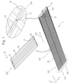
- Fig. 1 shows a perspective view of the deployable solar array 1 when deployed.
- Fig. 2 shows how the deployable solar array 1 is folded.
- the deployable solar array 1 of Fig. 1 converts sunlight energy into electric power and supplies the converted electric power to a satellite or a space system.
- the deployable solar array 1 includes multiple frame body units 10. As shown in Fig. 1 , the multiple frame body units 10 align in a linear form upon deployment. Fig. 1 indicates X, Y, and Z coordinates. For drawings with the coordinates indicated therein, the coordinates correspond to each other.
- the deployable solar array 1 of Fig. 1 is formed of two rows: a first row 101 and a second row 102, in which the multiple frame body units 10 are arrayed in a straight line direction 103.
- the X, Y, and Z coordinates are such that when the deployable solar array 1 is deployed, an X-Y plane is a plane that is formed by multiple light receiving surfaces, which are discussed later, and Y-axis direction is the straight line direction 103.
- Z axis is one of the normal directions to the X-Y plane.
- the first row 101 is formed of 23 frame body units 10.
- the second row 102 is also formed of 23 frame body units 10.
- the deployable solar array 1 is formed of two rows: the first row 101 and the second row 102, the deployable solar array 1 may be formed of one row or be formed of three or more rows.
- the first row 101 and the second row 102 are each formed of 23 frame body units 10 in the illustrated example, the number of frame body units 10 that form a row is not limited.
- the two frame body units 10 that neighbor each other in the straight line direction 103 during deployment may be called one frame body unit 10 and the other frame body unit 10, respectively.
- Fig. 1 shows an enlarged view of an area 501 of the deployable solar array 1 and an enlarged view of an area 502.
- the enlarged view of the area 501 illustrates hinge coupling of one frame body unit 10 and the other frame body unit 10.
- the enlarged view of the area 502 shows a frame body unit 10 with multiple solar cells 40 arranged thereon.
- one frame body unit 10 is coupled by a hinge 50 to the other frame body unit 10 that neighbors it during deployment.
- one frame body unit 10 overlies the other frame body unit 10 so as to cover the other frame body unit 10 by turning around the hinge 50.
- the multiple frame body units 10 can be stowed in layers by the one frame body unit 10 covering the other frame body unit 10.
- the deployable solar array 1 is folded such that the positions of the hinges 50 alternate between a peak and a valley across the multiple frame body units 10, until the frame body units 10 are stacked in layers.
- the orientation of the peak is in the Z-axis direction and the orientation of the valley is in the opposite direction of the Z-axis direction.
- each frame body unit 10 of the multiple frame body units 10 includes a frame body 20 and a film 30.
- Fig. 3 is a diagram schematically showing a structure of the frame body 20.
- the frame body 20 defines a frame shape.
- the frame body 20 is made of a beam having a simple cross-sectional shape in the interest of mass productivity.
- metal or carbon fiber can be used as material.
- the frame body 20 is structured in a polygonal shape, for example, by combining multiple beams by mechanical fastening or bonding.
- the frame body 20 shown in Fig. 3 is formed in a rectangular frame shape from multiple beams having L-shaped cross sections.
- the L-shaped cross section is an example and the shape of the cross section is not limited.
- Fig. 3 indicates an A-A section and a B-B section.
- the frame shape of the frame body 20 forms an opening 21.
- Fig. 4 shows the film 30 attached to the frame body 20.
- the solar cell 40 is not illustrated.
- Fig. 4 shows a C1-C1 section, a C2-C2 section, and the film 30 in deployed position.
- the C1-C1 section and the C2-C2 section correspond to the A-A section and the B-B section in Fig. 3 .
- the film 30 is formed of polymeric material.
- the film 30 is shown in broken line. In the drawings described below, the film 30 may be shown in broken line.
- the film 30 is attached to the frame body 20.
- the film 30 appears as a mounting surface 31 in the opening 21 that is formed by the frame shape defined by the frame body 20.
- multiple solar cells 40 are mounted on the mounting surface 31 of the film 30.
- the multiple solar cells 40 are mounted on the mounting surface 31 of the film 30. As depicted in Fig. 1 , the multiple solar cells 40 disposed on the film 30 of a frame body unit 10 form an electric circuit 43. Each one of the multiple trapezoid shapes depicted in the frame body unit 10 in Fig. 1 is a solar cell 40.
- the electric circuit 43 outputs solar-generated electric power from an output line 44. The output line 44 will be discussed later.
- the entire light receiving surfaces 42 face one another, which has the effect below. Note that since the direction from the mounting surface 31 toward the backside 32 of the mounting surface 31 represents the downward direction 34, the downward direction 34 and the opposite direction, discussed later, are reverse for the second and fourth frame body units 10 from the top in Fig. 6 , for example, with respect to the lowermost frame body unit 10 in Fig. 6 .
- the light receiving surface 41 of the solar cell 40 is covered with cover glass in order to protect it against radiation degradation in a space environment.
- the cover glass covering the light receiving surface 41 is subject to a mechanical damage risk associated with a contact with other components in a vibration environment during launch of a rocket.
- the mounting surface 31 of the film 30 is located below the frame body 20 in the downward direction 34, which is the direction from the mounting surface 31 toward the backside 32 of the mounting surface 31, the intervals between the opposing entire light receiving surfaces 42 is allowed to be large to a certain degree.
- contact between the entire light receiving surfaces 42 and damage to the entire light receiving surfaces 42 can be prevented by ensuring a spatial distance between the entire light receiving surfaces 42 without a component or material to directly protect the light receiving surfaces.
- a thermal deformation absorption structure 60 for attaching the film 30 to the frame body 20 is described.
- Fig. 7 shows the frame body unit 10, where the solar cells 40 are not illustrated.
- Fig. 8 shows three types in the E-E section that are included in the thermal deformation absorption structure 60.
- the deployable solar array 1 includes the thermal deformation absorption structure 60 to relieve thermal deformation of the film 30 with respect to the frame body 20 as a structure for attaching the film 30 and the frame body 20.
- the thermal deformation absorption structure 60 is a structure that attaches the film 30 to the frame body 20 for the entire periphery of the frame body 20.
- Fig. 8 shows that one of the three types, type 1 to type 3, is used in the E-E section.
- the E-E section is a cross section employed for illustration, and the three types, type 1 to type 3, are disposed at multiple points throughout the periphery of the frame body 20.
- the thermal deformation absorption structure 60 includes a hook-and-loop fastener structure 61 of type 1.
- the hook-and-loop fastener structure 61 attaches the film 30 to the frame body 20 by sticking a film hook-and-loop fastener 70b, which is a hook-and-loop fastener attached to the film 30, to a frame body hook-and-loop fastener 70a, which is a hook-and-loop fastener attached to the frame body 20.
- Type 1 in Fig. 8 shows the hook-and-loop fastener structure 61.
- the thermal deformation absorption structure 60 mainly uses the hook-and-loop fastener structure 61, and uses the mechanical fastening approach shown in Fig. 8 as types 2 and 3 together as an aid in attachment. Both type 2 and type 3 may be used with type 1 or either one of them may be used with type 1.
- Types 2 and 3 are structured such that a stem 23 of a shaft 22, which has the stem 23 and is attached to the frame body 20, passes through a through hole 33 formed in the film 30.
- Type 2 is structured such that the stem 23 of a pin 26 as the shaft 22, which has the stem 23 and is attached to the frame body 20, passes through the through hole 33 formed in the film 30.
- Type 3 is configured to use a set of a screw 27 and a nut 28 or a rivet.
- Type 3 in Fig. 8 shows a set of the screw 27 and the nut 28.
- the structure is such that the stem 23 of the screw 27 as the shaft 22, which has the stem 23 and is attached to the frame body 20, passes through the through hole 33 formed in the film 30, as shown in Fig. 8 .
- the screw 27 is attached to the frame body 20 with the nut 28.
- a rivet is used as type 3
- the structure is such that the stem of the rivet as the shaft, which has the stem and is attached to the frame body, passes through the through hole 33 formed in the film 30, in a similar manner to the screw 27.
- the set of the screw 27 and the nut 28 may be employed, a rivet may be employed, or both the set of the screw 27 and the nut 28 and a rivet may be employed.
- Type 2 is loose attachment that allows the film 30 to move in an axis direction 29 in which the stem 23 extends.
- type 3 is tight attachment that prevents the film 30 from moving in the axis direction 29.
- the means of attaching the film 30 to the frame body 20 is the thermal deformation absorption structure 60.
- the thermal deformation absorption structure 60 mainly uses the hook-and-loop fastener structure 61 shown as type 1, and uses mechanical fastening that employs the pin 26 shown as type 2, and the set of the screw 27 and the nut or a rivet shown as type 3 in combination as an aid. Any of combined use of type 1 and type 2, combined use of type 1 and type 3, and combined use of type 1, type 2, and type 3 is possible.
- the hook-and-loop fastener structure 61 of type 1 as the primary means of fixation has flexibility in attachment of the frame body 20 and the film 30.
- the hook-and-loop fastener structure 61 can relieve thermal deformation of the film 30 with respect to the frame body 20 which is caused by linear expansion difference between components in a heat cycle environment in space.
- the thermal deformation absorption structure 60 uses mechanical fastening, such as type 2 and type 3, in combination, it is configured to allow relative movement of the film 30 to the frame body 20 in response to thermal deformation.
- the configuration described above can eliminate the necessity for a tension adjustment mechanism, which is essential for the conventional flexible types.
- the frame body unit 10 is thus simple in structure, so that lower cost and mass productivity can be ensured.
- Fig. 9 shows the D-D section of Fig. 5 .
- the frame body 20 has the projection 24.
- the projection 24 of the frame body 20 of one frame body unit 10 nips and fixes the film 30 of the one frame body unit 10 and the film 30 of the other frame body unit 10 with the projection 24 of the frame body 20 of the other frame body unit 10.
- the frame body units 10 are denoted as frame body units #1, #2, #3, #4 from the top in order.
- the frame bodies 20 of the frame body units #1, #2, #3, #4 are denoted as frame bodies #1, #2, #3, #4, respectively.
- the frame body #2 and the frame body #3 and the frame body #3 and the frame body #4.
- their entire light receiving surfaces 42 face each other.
- the frame body #2 has the projection 24 at an end in the stacking direction
- the frame body #3 has the projection 24 at an end in the stacking direction on the side facing the frame body #2.
- the film 30 of the frame body unit #2 and the film 30 of the frame body unit #3 are nipped and fixed by the projection 24 of the frame body #2 and the projection 24 of the frame body #3.
- the films on which the backsides of the entire light receiving surfaces 42 are positioned face each other.
- the projection 24 of the frame body #3 is positioned between the frame body #3 and the film 30, and the projection 24 of the frame body #4 is positioned between the frame body #4 and the film 30.
- the film 30 of the frame body unit #3 and the film 30 of the frame body unit #4 are nipped and fixed by the projection 24 of the frame body #3 and the projection 24 of the frame body #4.
- the deployable solar array 1 When the deployable solar array 1 is deployed, it is configured to loosely fix the frame bodies and films in order to relieve thermal deformation due to heat cycle, as described in Fig. 8 . Furthermore, when the deployable solar array 1 is stowed, that is, when it is launched on a rocket, the films are rigidly fixed to the frame bodies 20, which serve as structures, by way of the projections 24 provided on the frame bodies 20.
- the film 30 thus can withstand a launch vibration environment. Accordingly, for the film 30, a simple structure that can withstand vibration during a launch and a simple structure that can withstand the heat cycle during deployment described in Fig. 8 can be achieved.
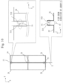
- Fig. 10 shows a mechanical contact 25.
- One frame body unit 10 and the other frame body unit 10 have the mechanical contact 25 that transmits a load to each other during deployment.
- Fig. 10 shows the mechanical contact 25 that transmits a load between the neighboring frame bodies 20 to each other during deployment.
- Fig. 10 shows the four frame body units 10 in an area 505 of Fig. 1 .
- the solar cells 40 are not illustrated.
- the mechanical contact 25 is formed of a member 25A disposed on one frame body 20 and a member 25B disposed on the other frame body 20. Thanks to the mechanical contact 25, the deployed shape of the deployable solar array 1 is maintained only by the rigidity of the frame body 20.
- the hinge 50 and the mechanical contact 25 are also configured to be able to receive moment load by ensuring a spatial distance in X-Y plan view.
- each unit is not formed of a rigid body that has sufficient rigidity to constitute the entire solar array by itself.
- each unit is made of a film alone or a thin plate.
- a support structure such as a mast or a storable tubular extendible member is essential for ensuring the rigidity during deployment.
- a support structure has disadvantages such as poor design scalability, unsuitability for mass production, and high cost and bulkiness due to the complexity of the support structure and a deployment mechanism for the support structure.
- the configuration provided with the mechanical contact 25 eliminates the necessity for a support structure and its deployment mechanism.
- each frame body 20 is responsible for rigidity and a load path between the frame bodies 20 is created by the mechanical contacts 25, thus ensuring the rigidity of the entire deployable solar array 1. So, the deployable solar array 1 that is inexpensive, space saving, and advantageous for mass productivity can be achieved.
- Fig. 11 shows the output lines 44 for drawing electric power from the frame body units 10.
- the multiple solar cells 40 form the electric circuit 43.
- Each frame body unit 10 includes the output line 44 connected to the electric circuit 43.
- each frame body unit 10 When multiple frame body units 10 are deployed, the output line 44 of each frame body unit 10 is positioned along the side surfaces of the multiple frame body units 10 in the same direction 506, which is one direction in the linear form.
- the output line 44 connected to each electric circuit 43 formed by multiple solar cells 40 is drawn from a side of the frame body 20 and routed along the side surfaces of the frame bodies 20.
- the output line 44 out of the frame body 20 is routed toward the root of the deployable solar array 1, that is, in the same direction 506, without passing through a connector or a terminal.
- the three frame body units 10 in Fig. 11 are denoted as frame body units #1, #2, #3 from the left.
- the output lines 44 of the frame body units #1, #2, #3 are denoted as output lines #1, #2, #3, respectively.
- the output line #1 runs along the side surface of the frame body unit #1, output lines #1, #2 run along the side surface of the frame body unit #2, and output lines #1, #2, #3 run along the side surface of the frame body unit #3. Finally, output lines #1, #2, #3, ..., #N run along the side surface of a frame body unit #N. That is, if output lines are stacked on top of each other in the thickness direction, it would be infeasible with a flat pack that has a small thickness of the frame body 20.
- the deployable solar array 1 is configured such that a bundle of output lines is placed flat and the width of the bundle of output lines increases as it is closer to the root.
- the multiple output lines 44 running in the same direction 506 reach a satellite or a space system.
- a configuration for transmitting electric power to a satellite or a space system is conventionally structured such that connectors mounted on individual panels are connected.
- the configuration of the output line 44 shown in Fig. 11 does not require wire coupling between frame body units 10 and does not require a connector for each frame body unit 10.
- the number of components can be decreased, the reliability of performance can be ensured, and cost can be reduced.
- necessity for circuit design and wiring design according to the required power of the solar array is eliminated.
- the deployable solar array 1 allows flexible design of the deployable solar array 1 according to the required power by adjusting the number of frame body units 10 in relation to the required power.
- the deployable solar array 1 can have a structure that is scalable in terms of design for the required power, and the work period and cost can be reduced.
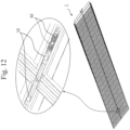
- Fig. 12 shows an elastic body 80, which is disposed independently from the hinge 50, which forms a rotation shaft, and produces deployment power for the deployable solar array 1.
- the deployable solar array 1 has the elastic body 80 which stores elastic energy for deploying one frame body unit 10 relative to the other frame body unit 10 during stowage, between the one frame body unit 10 and the other frame body unit 10.
- Fig. 12 shows a coil spring as an example of the elastic body 80.
- the elastic body 80 stores elastic energy for causing a deployment motion from the stowed position to the deployed position upon transition from the deployed position to the stowed position shown in Fig. 2 .
- the elastic body 80 simplifies the structure of the deployment mechanism created by the hinge 50 and the elastic body 80. Thus, cost reduction can be achieved. Furthermore, since the deployment mechanism can be created by a simple structure, that is, the combination of the hinge 50 and the elastic body 80, the mass productivity of the deployable solar array 1 can be ensured. Also, depending on the size of the solar array, separate design has been needed. In terms of this, the deployable solar array 1 can accommodate the sizing of deployment torque by adjusting the number of elastic bodies 80 that are disposed between one frame body unit 10 and the other frame body unit 10. This can provide a structure that is scalable for the solar array size. Hence, separate designs, like those for conventional solar array units, are no longer necessary, and the work period and cost can be reduced.
- Figs. 13 and 14 illustrate a deployment delay mechanism 90.
- Fig. 13 shows an F-F section in which the deployment delay mechanism 90 appears.
- Fig. 14 shows deployment by the deployment delay mechanism 90.
- the deployable solar array 1 includes the deployment delay mechanism 90 that, for a start frame body unit 10 as the frame body unit #1 that is located at one end of the layers during stowage, through to an end frame body unit #E located at the other end of the layers during stowage, causes a deployment motion to begin from the start frame body unit #1 toward the end frame body unit #E sequentially.
- the deployment delay mechanism 90 delayed deployment motion by the deployment delay mechanism 90 is described.
- the deployment delay mechanism 90 is created by multiple hinges 50, multiple elastic bodies 80, multiple cams, and multiple rollers.
- the frame body units 10 are denoted like frame body unit #1.
- Fig. 14 multiple frame body units 10 from the frame body unit #1 to the frame body unit #E are folded in layers.
- the multiple frame body units 10 from the frame body unit #1 to the frame body unit #E are folded in layers in a stacking direction 507.
- the deployable solar array 1 has the deployment delay mechanism 90.
- the deployment delay mechanism 90 is created by multiple hinges 50, multiple elastic bodies 80, multiple cams, and multiple rollers in their entities.
- a conventional solar array typically contains a synchronization mechanism for synchronizing the overall motion. So, it needs adjustment during assembly and requires separate designs for different solar array sizes.
- the deployment delay mechanism 90 does not require such separate designs or adjustment after assembly. Thus, a structure that is scalable for the solar array size can be achieved and the work period and cost can be reduced.
Landscapes
- Engineering & Computer Science (AREA)
- Remote Sensing (AREA)
- Aviation & Aerospace Engineering (AREA)
- Life Sciences & Earth Sciences (AREA)
- Sustainable Development (AREA)
- Photovoltaic Devices (AREA)
- Physics & Mathematics (AREA)
- Astronomy & Astrophysics (AREA)
- General Physics & Mathematics (AREA)
Abstract
Description
- The present disclosure relates to deployable solar arrays.
- For solar array as reduce power generation for artificial satellites or space systems, features such as low cost, mass productivity, stowability are required.
- Conventional rigid type solar arrays are limited in attaining these features.
- Accordingly, companies are expanding their developments and applications of various flexible types for achieving high stowability with the intention of carrying multiple satellites on a rocket, which is directly linked to cost.
- While approaches to flexible type solar arrays can be subdivided to different types, they can be generally classified into rollout type and flat pack type. Each has the features shown below.
- A long, flexible sheet with solar cells mounted thereon is stowed by being rolled around a mandrel of a rolling mechanism installed on a satellite body structure.
- The solar cell sheet is rolled out and deployed by a flexible storable tubular extendible member or mast made of carbon fiber sheet.
- Rigidity during deployment is ensured by the storable tubular extendible member or mast.
- Deployment power is provided by the elastic energy of the storable tubular extendible member or mast or by an actuator mounted at the root.
- Since the light receiving surfaces of the cells do not face each other due to the sheet rolling configuration, measures against interference between cells are easy compared to the flat pack type. The rollout type is suited for larger sizes, as it can cover ultra-large classes (classes with a power generation of 25 kW or more).
- The larger the size, the smaller the proportion of the cost and mass of a deployment mechanism and a support mechanism relative to power scale; thus, there are advantages in cost and mass.
- On the other hand, it is poor in scalability because a mandrel for rolling up the solar cell sheet is essential and it poses limitations on the height during stowage and the volume during stowage and also the deployment mechanism is relatively complicated.
- Flexible sheets or thin plates with solar cells mounted thereon are connected to each other in a strip form and stowed like a folding screen. Some are deployed by springs mounted on deployment shafts and others are deployed by a storable tubular extendible member or a mast like the rollout type. To increase the size, rigidity during deployment poses a challenge. Thus, almost all of the large-sized flat pack types that presently exist in the world have storable tubular extendible members or masts. As the flat pack type does not require a mandrel for rolling up a sheet, it can be small in height during stowage and in volume during stowage.
- A configuration that requires no storable tubular extendible member or mast is advantageous in scalability and hence in cost and mass productivity. On the other hand, it is disadvantageous for ultra-large classes, such as those covered by the rollout type, in terms of cost and mass.
-
- Patent Literature 1:
US 2018/0309008 - Patent Literature 2:
US 10189582 - Non-Patent Literature 1:: Bao Hoang; Steve White; Brian Spence; Steven Kiefer, "Commercialization of Deployable Space Systems' roll-out solar array (ROSA) technology for Space Systems Loral (SSL) solar arrays" Aerospace Conference, 30 June 2016.
-
Patent Literature 1 is a publication on a large-sized, flat pack type solar array. The large-sized, flat pack type solar array ofPatent Literature 1 uses storable tubular extendible member actuator extension. -
Patent Literature 2 is a patent publication of a storable tubular extendible member -free, small-sized, rollout type solar array. - Non-Patent Literature 1 is a paper on a large-sized, rollout type solar array.
- The large-sized, rollout type solar array according to the paper is of a self-extension storable tubular extendible member type.
- As mentioned above, a storable tubular extendible member is required in order to increase the size of a solar array (
Patent Literature 1, Non-Patent Literature 1). Since a mechanism to develop the storable tubular extendible member, whether an actuator or self-development, is complicated, a storable tubular extendible member is poor in scalability and has challenges in mass productivity and cost. Storable tubular extendible member-less configurations are limited to small-sized solar arrays because they cannot ensure rigidity during deployment (Patent Literature 2). - When a rolling mandrel is employed, the mandrel poses limitations on the height and volume during stowage, thus having a challenge of stowage ratio (
Patent Literature 1, Non-Patent Literature 1). - An object of the present disclosure is to provide a solar array of flat pack type that does not require a storable tubular extendible member and a mast, allows for larger sizes, has good stowability, and is simple in structure and suited for mass production.
- A deployable solar array according to the present disclosure includes a plurality of frame body units.
- Each frame body unit of the plurality of frame body units includes
- a frame body defining a frame shape, and
- a film that is attached to the frame body and appears as a mounting surface in an opening that is formed by the frame shape defined by the frame body, with a plurality of solar cells mounted on the mounting surface.
- According to the present disclosure, a solar array of flat pack type that does not require a storable tubular extendible member and a mast, allows for larger sizes, has good stowability, and is simple in structure and suited for mass production can be provided.
-
-
Fig. 1 is a diagram ofEmbodiment 1, showing a perspective view of a deployablesolar array 1 when deployed. -
Fig. 2 is a diagram ofEmbodiment 1, showing how the deployablesolar array 1 is folded. -
Fig. 3 is a diagram ofEmbodiment 1, schematically showing a structure of aframe body 20. -
Fig. 4 is a diagram ofEmbodiment 1, showing afilm 30 attached to theframe body 20. -
Fig. 5 is a diagram ofEmbodiment 1, showing the deployablesolar array 1 when stowed. -
Fig. 6 is a diagram ofEmbodiment 1, showing a D-D section inFig. 5 . -
Fig. 7 is a diagram ofEmbodiment 1, showing aframe body unit 10, wheresolar cells 40 are not illustrated. -
Fig. 8 is a diagram ofEmbodiment 1, showing three types of thermaldeformation absorption structures 60 in an E-E section. -
Fig. 9 is a diagram ofEmbodiment 1, showing aprojection 24 in the D-D section. -
Fig. 10 is a diagram ofEmbodiment 1, showing amechanical contact 25. -
Fig. 11 is a diagram ofEmbodiment 1, showingoutput lines 44 for drawing electric power fromframe body units 10. -
Fig. 12 is a diagram ofEmbodiment 1, showing anelastic body 80 that produces deployment power for the deployablesolar array 1. -
Fig. 13 is a diagram ofEmbodiment 1, showing an F-F section in which a deployment delay mechanism 90 appears. -
Fig. 14 is a diagram ofEmbodiment 1, showing deployment of the deployablesolar array 1 by the deployment delay mechanism 90. - In the description of an embodiment and the drawings, the same elements and corresponding elements are given the same reference characters. Description on elements with the same reference characters are omitted or simplified as appropriate.
- A deployable
solar array 1 inEmbodiment 1 will be described with reference toFigs. 1 to 14 . - Referring to
Figs. 1 and2 , a basic configuration of the deployablesolar array 1 is described. -
Fig. 1 shows a perspective view of the deployablesolar array 1 when deployed.Fig. 2 shows how the deployablesolar array 1 is folded. The deployablesolar array 1 ofFig. 1 converts sunlight energy into electric power and supplies the converted electric power to a satellite or a space system. - The deployable
solar array 1 includes multipleframe body units 10. As shown inFig. 1 , the multipleframe body units 10 align in a linear form upon deployment.Fig. 1 indicates X, Y, and Z coordinates. For drawings with the coordinates indicated therein, the coordinates correspond to each other. The deployablesolar array 1 ofFig. 1 is formed of two rows: afirst row 101 and asecond row 102, in which the multipleframe body units 10 are arrayed in astraight line direction 103. The X, Y, and Z coordinates are such that when the deployablesolar array 1 is deployed, an X-Y plane is a plane that is formed by multiple light receiving surfaces, which are discussed later, and Y-axis direction is thestraight line direction 103. Z axis is one of the normal directions to the X-Y plane. - The
first row 101 is formed of 23frame body units 10. Thesecond row 102 is also formed of 23frame body units 10. Although the deployablesolar array 1 is formed of two rows: thefirst row 101 and thesecond row 102, the deployablesolar array 1 may be formed of one row or be formed of three or more rows. Although thefirst row 101 and thesecond row 102 are each formed of 23frame body units 10 in the illustrated example, the number offrame body units 10 that form a row is not limited. - The two
frame body units 10 that neighbor each other in thestraight line direction 103 during deployment may be called oneframe body unit 10 and the otherframe body unit 10, respectively.Fig. 1 shows an enlarged view of anarea 501 of the deployablesolar array 1 and an enlarged view of anarea 502. The enlarged view of thearea 501 illustrates hinge coupling of oneframe body unit 10 and the otherframe body unit 10. The enlarged view of thearea 502 shows aframe body unit 10 with multiplesolar cells 40 arranged thereon. As shown in the enlarged view of thearea 501, in thefirst row 101, oneframe body unit 10 is coupled by ahinge 50 to the otherframe body unit 10 that neighbors it during deployment. - This applies to the
second row 102 as well. - As shown in
Fig. 2 , oneframe body unit 10 overlies the otherframe body unit 10 so as to cover the otherframe body unit 10 by turning around thehinge 50. The multipleframe body units 10 can be stowed in layers by the oneframe body unit 10 covering the otherframe body unit 10. The deployablesolar array 1 is folded such that the positions of thehinges 50 alternate between a peak and a valley across the multipleframe body units 10, until theframe body units 10 are stacked in layers. Here, the orientation of the peak is in the Z-axis direction and the orientation of the valley is in the opposite direction of the Z-axis direction. - The
frame body unit 10 is now described. As shown inFig. 1 , eachframe body unit 10 of the multipleframe body units 10 includes aframe body 20 and afilm 30. -
Fig. 3 is a diagram schematically showing a structure of theframe body 20. Theframe body 20 defines a frame shape. Theframe body 20 is made of a beam having a simple cross-sectional shape in the interest of mass productivity. For the beam, metal or carbon fiber can be used as material. Theframe body 20 is structured in a polygonal shape, for example, by combining multiple beams by mechanical fastening or bonding. Theframe body 20 shown inFig. 3 is formed in a rectangular frame shape from multiple beams having L-shaped cross sections. The L-shaped cross section is an example and the shape of the cross section is not limited.Fig. 3 indicates an A-A section and a B-B section. The frame shape of theframe body 20 forms anopening 21. -
Fig. 4 shows thefilm 30 attached to theframe body 20. InFig. 4 , thesolar cell 40 is not illustrated.Fig. 4 shows a C1-C1 section, a C2-C2 section, and thefilm 30 in deployed position. The C1-C1 section and the C2-C2 section correspond to the A-A section and the B-B section inFig. 3 . Thefilm 30 is formed of polymeric material. InFig. 4 , thefilm 30 is shown in broken line. In the drawings described below, thefilm 30 may be shown in broken line. Thefilm 30 is attached to theframe body 20. Thefilm 30 appears as a mountingsurface 31 in theopening 21 that is formed by the frame shape defined by theframe body 20. As shown inFig. 1 , multiplesolar cells 40 are mounted on the mountingsurface 31 of thefilm 30. - The multiple
solar cells 40 are mounted on the mountingsurface 31 of thefilm 30. As depicted inFig. 1 , the multiplesolar cells 40 disposed on thefilm 30 of aframe body unit 10 form anelectric circuit 43. Each one of the multiple trapezoid shapes depicted in theframe body unit 10 inFig. 1 is asolar cell 40. Theelectric circuit 43 outputs solar-generated electric power from anoutput line 44. Theoutput line 44 will be discussed later. -
- Involving a long work period and high cost because of the multiple manufacturing steps of a rigid panel.
- Not suited for mass production because solar cells need to be mounted for each panel basis and cannot be manufactured continuously.
- Having a limitation in reducing the thickness in order to ensure rigidity strength.
- The thickness of a rigid panel is a bottleneck with a solar array of rigid panel type, due to the necessity to reduce the panel size per panel for space saving in mounting on a satellite or a space system. Because of the thickness of a rigid panel, if the light receiving area is sought, it would lead to a too large stowage height in the stacking direction of the panels when panels are folded and stowed like a folding screen.
-
- The structure described above achieves characteristics that are advantageous for low cost, space saving, and mass productivity, compared to the widely used conventional rigid panel type.
- With the structure of the deployable
solar array 1, theframe body 20 can be structured by combining mass-produceable beams made of metal or carbon fiber and having the same simple cross-sectional shape by mechanical fastening. Thus, the rigidity of the beams is easy to ensure and the thickness of theframe body unit 10 equivalent to one panel can be reduced. That is to say, the thickness of theframe body 20 can be reduced. - In the deployable
solar array 1, multiplesolar cells 40 are mounted on thefilm 30. This configuration allows for continuous manufacture compared to the rigid panel type, for which productivity is separated for each panel. - As a result, low cost and mass productivity can be ensured.
-
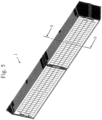
Fig. 5 shows the deployablesolar array 1 when stowed.Fig. 6 shows a D-D section inFig. 5 . - Referring to the lowermost
frame body unit 10 inFig. 6 , the mountingsurface 31 of thefilm 30 is located below theframe body 20 in adownward direction 34, which is the direction from the mountingsurface 31 toward abackside 32 of the mountingsurface 31. Eachsolar cell 40 of the multiplesolar cells 40 has a backside of alight receiving surface 41 thereof attached to the mountingsurface 31. As shown inFig. 6 , taking the second oneframe body unit 10 from the top and the third otherframe body unit 10 from the top as an example, their entirelight receiving surfaces 42 formed by the light receiving surfaces 41 of thesolar cells 40 face each other during stowage. This configuration allows the multiplesolar cells 40 to be arranged on the side of thedownward direction 34, like the lowermostframe body unit 10 inFig. 6 . Thus, when stowed as inFig. 6 , the entirelight receiving surfaces 42 face one another, which has the effect below. Note that since the direction from the mountingsurface 31 toward thebackside 32 of the mountingsurface 31 represents thedownward direction 34, thedownward direction 34 and the opposite direction, discussed later, are reverse for the second and fourthframe body units 10 from the top inFig. 6 , for example, with respect to the lowermostframe body unit 10 inFig. 6 . - The
light receiving surface 41 of thesolar cell 40 is covered with cover glass in order to protect it against radiation degradation in a space environment. Thus, the cover glass covering thelight receiving surface 41 is subject to a mechanical damage risk associated with a contact with other components in a vibration environment during launch of a rocket. However, since the mountingsurface 31 of thefilm 30 is located below theframe body 20 in thedownward direction 34, which is the direction from the mountingsurface 31 toward thebackside 32 of the mountingsurface 31, the intervals between the opposing entire light receiving surfaces 42 is allowed to be large to a certain degree. Thus, contact between the entirelight receiving surfaces 42 and damage to the entirelight receiving surfaces 42 can be prevented by ensuring a spatial distance between the entirelight receiving surfaces 42 without a component or material to directly protect the light receiving surfaces. Hence, there are advantages in terms of cost and mass productivity. - Furthermore, in
Fig. 6 , when the deployablesolar array 1 is stowed, a light receivingsurface interval 45 between the entirelight receiving surfaces 42 is sized to be twice or more the thickness of theframe body 20. Here, the thickness of theframe body 20 refers to amaximal width 36 in thedownward direction 34 and anopposite direction 35 of thedownward direction 34, when described for the lowermostframe body unit 10 inFig. 6 . As shown inFig. 6 , the reverse sides of the light receiving surfaces 41 of thesolar cells 40 can be placed back to back with theirrespective films 30 in between, and the interval between the entirelight receiving surfaces 42 can be secured such that it is twice or more the thickness of theframe body 20. This can maintain the intervals between the entirelight receiving surfaces 42 of the neighboringframe body units 10 when the deployablesolar array 1 is stowed. Also in terms of this, a similar effect to that of the above-described configuration, "the mountingsurface 31 of thefilm 30 is located below theframe body 20 in thedownward direction 34", is provided. - Referring to
Figs. 7 and8 , a thermaldeformation absorption structure 60 for attaching thefilm 30 to theframe body 20 is described. -
Fig. 7 shows theframe body unit 10, where thesolar cells 40 are not illustrated. -
Fig. 8 shows three types in the E-E section that are included in the thermaldeformation absorption structure 60. As shown inFig. 7 , the deployablesolar array 1 includes the thermaldeformation absorption structure 60 to relieve thermal deformation of thefilm 30 with respect to theframe body 20 as a structure for attaching thefilm 30 and theframe body 20. The thermaldeformation absorption structure 60 is a structure that attaches thefilm 30 to theframe body 20 for the entire periphery of theframe body 20.Fig. 8 shows that one of the three types,type 1 to type 3, is used in the E-E section. The E-E section is a cross section employed for illustration, and the three types,type 1 to type 3, are disposed at multiple points throughout the periphery of theframe body 20. The thermaldeformation absorption structure 60 includes a hook-and-loop fastener structure 61 oftype 1. The hook-and-loop fastener structure 61 attaches thefilm 30 to theframe body 20 by sticking a film hook-and-loop fastener 70b, which is a hook-and-loop fastener attached to thefilm 30, to a frame body hook-and-loop fastener 70a, which is a hook-and-loop fastener attached to theframe body 20. -
Type 1 inFig. 8 shows the hook-and-loop fastener structure 61. The thermaldeformation absorption structure 60 mainly uses the hook-and-loop fastener structure 61, and uses the mechanical fastening approach shown inFig. 8 astypes type 2 andtype 3 may be used withtype 1 or either one of them may be used withtype 1.Types stem 23 of a shaft 22, which has thestem 23 and is attached to theframe body 20, passes through a throughhole 33 formed in thefilm 30.Type 2 is structured such that thestem 23 of a pin 26 as the shaft 22, which has thestem 23 and is attached to theframe body 20, passes through the throughhole 33 formed in thefilm 30. -
Type 3 is configured to use a set of a screw 27 and anut 28 or a rivet.Type 3 inFig. 8 shows a set of the screw 27 and thenut 28. When the set of the screw 27 and thenut 28 is used astype 3, the structure is such that thestem 23 of the screw 27 as the shaft 22, which has thestem 23 and is attached to theframe body 20, passes through the throughhole 33 formed in thefilm 30, as shown inFig. 8 . The screw 27 is attached to theframe body 20 with thenut 28. When a rivet is used astype 3, the structure is such that the stem of the rivet as the shaft, which has the stem and is attached to the frame body, passes through the throughhole 33 formed in thefilm 30, in a similar manner to the screw 27. For the mechanical fastening astype 3, the set of the screw 27 and thenut 28 may be employed, a rivet may be employed, or both the set of the screw 27 and thenut 28 and a rivet may be employed. -
Type 2 is loose attachment that allows thefilm 30 to move in anaxis direction 29 in which thestem 23 extends. In contrast,type 3 is tight attachment that prevents thefilm 30 from moving in theaxis direction 29. - As described above, the means of attaching the
film 30 to theframe body 20 is the thermaldeformation absorption structure 60. The thermaldeformation absorption structure 60 mainly uses the hook-and-loop fastener structure 61 shown astype 1, and uses mechanical fastening that employs the pin 26 shown astype 2, and the set of the screw 27 and the nut or a rivet shown astype 3 in combination as an aid. Any of combined use oftype 1 andtype 2, combined use oftype 1 andtype 3, and combined use oftype 1,type 2, andtype 3 is possible. - The hook-and-loop fastener structure 61 of
type 1 as the primary means of fixation has flexibility in attachment of theframe body 20 and thefilm 30. The hook-and-loop fastener structure 61 can relieve thermal deformation of thefilm 30 with respect to theframe body 20 which is caused by linear expansion difference between components in a heat cycle environment in space. Although the thermaldeformation absorption structure 60 uses mechanical fastening, such astype 2 andtype 3, in combination, it is configured to allow relative movement of thefilm 30 to theframe body 20 in response to thermal deformation. - The configuration described above can eliminate the necessity for a tension adjustment mechanism, which is essential for the conventional flexible types. The
frame body unit 10 is thus simple in structure, so that lower cost and mass productivity can be ensured. - Referring to
Fig. 9 , a configuration for nipping and fixing thefilm 30 with aprojection 24 provided on theframe body 20 when the deployablesolar array 1 is stowed is described.Fig. 9 shows the D-D section ofFig. 5 . - As shown in
Fig. 9 , theframe body 20 has theprojection 24. With the multipleframe body units 10 being stowed in layers, theprojection 24 of theframe body 20 of oneframe body unit 10 nips and fixes thefilm 30 of the oneframe body unit 10 and thefilm 30 of the otherframe body unit 10 with theprojection 24 of theframe body 20 of the otherframe body unit 10. - This is described in more detail below. In
Fig. 9 , theframe body units 10 are denoted as framebody units # 1, #2, #3, #4 from the top in order. Theframe bodies 20 of the framebody units # 1, #2, #3, #4 are denoted asframe bodies # 1, #2, #3, #4, respectively. Consider theframe body # 2 and theframe body # 3, and theframe body # 3 and theframe body # 4. For theframe body # 2 and theframe body # 3, their entirelight receiving surfaces 42 face each other. In anarea 503, theframe body # 2 has theprojection 24 at an end in the stacking direction, while theframe body # 3 has theprojection 24 at an end in the stacking direction on the side facing theframe body # 2. - The
film 30 of the framebody unit # 2 and thefilm 30 of the framebody unit # 3 are nipped and fixed by theprojection 24 of theframe body # 2 and theprojection 24 of theframe body # 3. For theframe body # 3 and theframe body # 4, the films on which the backsides of the entirelight receiving surfaces 42 are positioned face each other. - In an
area 504, theprojection 24 of theframe body # 3 is positioned between theframe body # 3 and thefilm 30, and theprojection 24 of theframe body # 4 is positioned between theframe body # 4 and thefilm 30. Thefilm 30 of the framebody unit # 3 and thefilm 30 of the framebody unit # 4 are nipped and fixed by theprojection 24 of theframe body # 3 and theprojection 24 of theframe body # 4. - When the deployable
solar array 1 is deployed, it is configured to loosely fix the frame bodies and films in order to relieve thermal deformation due to heat cycle, as described inFig. 8 . Furthermore, when the deployablesolar array 1 is stowed, that is, when it is launched on a rocket, the films are rigidly fixed to theframe bodies 20, which serve as structures, by way of theprojections 24 provided on theframe bodies 20. - The
film 30 thus can withstand a launch vibration environment. Accordingly, for thefilm 30, a simple structure that can withstand vibration during a launch and a simple structure that can withstand the heat cycle during deployment described inFig. 8 can be achieved. -
Fig. 10 shows amechanical contact 25. Oneframe body unit 10 and the otherframe body unit 10 have themechanical contact 25 that transmits a load to each other during deployment. - This is described in more detail below. As shown in
Fig. 10 , themechanical contact 25 that transmits a load between the neighboringframe bodies 20 to each other during deployment is provided.Fig. 10 shows the fourframe body units 10 in anarea 505 ofFig. 1 . InFig. 10 , thesolar cells 40 are not illustrated. Themechanical contact 25 is formed of amember 25A disposed on oneframe body 20 and amember 25B disposed on theother frame body 20. Thanks to themechanical contact 25, the deployed shape of the deployablesolar array 1 is maintained only by the rigidity of theframe body 20. Thehinge 50 and themechanical contact 25 are also configured to be able to receive moment load by ensuring a spatial distance in X-Y plan view. - With a conventional flexible type solar array, each unit is not formed of a rigid body that has sufficient rigidity to constitute the entire solar array by itself. For example, each unit is made of a film alone or a thin plate. Thus, a support structure such as a mast or a storable tubular extendible member is essential for ensuring the rigidity during deployment. A support structure has disadvantages such as poor design scalability, unsuitability for mass production, and high cost and bulkiness due to the complexity of the support structure and a deployment mechanism for the support structure. However, the configuration provided with the
mechanical contact 25 eliminates the necessity for a support structure and its deployment mechanism. Essentially, eachframe body 20 is responsible for rigidity and a load path between theframe bodies 20 is created by themechanical contacts 25, thus ensuring the rigidity of the entire deployablesolar array 1. So, the deployablesolar array 1 that is inexpensive, space saving, and advantageous for mass productivity can be achieved. -
Fig. 11 shows theoutput lines 44 for drawing electric power from theframe body units 10. The multiplesolar cells 40 form theelectric circuit 43. Eachframe body unit 10 includes theoutput line 44 connected to theelectric circuit 43. - When multiple
frame body units 10 are deployed, theoutput line 44 of eachframe body unit 10 is positioned along the side surfaces of the multipleframe body units 10 in thesame direction 506, which is one direction in the linear form. - This is described in more detail below. As shown in
Fig. 11 , theoutput line 44 connected to eachelectric circuit 43 formed by multiplesolar cells 40 is drawn from a side of theframe body 20 and routed along the side surfaces of theframe bodies 20. Theoutput line 44 out of theframe body 20 is routed toward the root of the deployablesolar array 1, that is, in thesame direction 506, without passing through a connector or a terminal. The threeframe body units 10 inFig. 11 are denoted as framebody units # 1, #2, #3 from the left. The output lines 44 of the framebody units # 1, #2, #3 are denoted asoutput lines # 1, #2, #3, respectively. Theoutput line # 1 runs along the side surface of the framebody unit # 1,output lines # 1, #2 run along the side surface of the framebody unit # 2, andoutput lines # 1, #2, #3 run along the side surface of the framebody unit # 3. Finally,output lines # 1, #2, #3, ..., #N run along the side surface of a frame body unit #N. That is, if output lines are stacked on top of each other in the thickness direction, it would be infeasible with a flat pack that has a small thickness of theframe body 20. Thus, the deployablesolar array 1 is configured such that a bundle of output lines is placed flat and the width of the bundle of output lines increases as it is closer to the root. Themultiple output lines 44 running in thesame direction 506 reach a satellite or a space system. - A configuration for transmitting electric power to a satellite or a space system is conventionally structured such that connectors mounted on individual panels are connected. Hence, as the size of the solar array increases in relation to the required power, the number of components increases and also a separate wiring design is required according to the size. By contrast, the configuration of the
output line 44 shown inFig. 11 does not require wire coupling betweenframe body units 10 and does not require a connector for eachframe body unit 10. Thus, the number of components can be decreased, the reliability of performance can be ensured, and cost can be reduced. Also, by directly drawing theoutput lines 44 from the frame body units toward a satellite or a space system, necessity for circuit design and wiring design according to the required power of the solar array is eliminated. - That is, the deployable
solar array 1 allows flexible design of the deployablesolar array 1 according to the required power by adjusting the number offrame body units 10 in relation to the required power. - Thus, the deployable
solar array 1 can have a structure that is scalable in terms of design for the required power, and the work period and cost can be reduced. -
Fig. 12 shows anelastic body 80, which is disposed independently from thehinge 50, which forms a rotation shaft, and produces deployment power for the deployablesolar array 1. The deployablesolar array 1 has theelastic body 80 which stores elastic energy for deploying oneframe body unit 10 relative to the otherframe body unit 10 during stowage, between the oneframe body unit 10 and the otherframe body unit 10.Fig. 12 shows a coil spring as an example of theelastic body 80. Theelastic body 80 stores elastic energy for causing a deployment motion from the stowed position to the deployed position upon transition from the deployed position to the stowed position shown inFig. 2 . - The
elastic body 80 simplifies the structure of the deployment mechanism created by thehinge 50 and theelastic body 80. Thus, cost reduction can be achieved. Furthermore, since the deployment mechanism can be created by a simple structure, that is, the combination of thehinge 50 and theelastic body 80, the mass productivity of the deployablesolar array 1 can be ensured. Also, depending on the size of the solar array, separate design has been needed. In terms of this, the deployablesolar array 1 can accommodate the sizing of deployment torque by adjusting the number ofelastic bodies 80 that are disposed between oneframe body unit 10 and the otherframe body unit 10. This can provide a structure that is scalable for the solar array size. Hence, separate designs, like those for conventional solar array units, are no longer necessary, and the work period and cost can be reduced. -
Figs. 13 and14 illustrate a deployment delay mechanism 90. -
Fig. 13 shows an F-F section in which the deployment delay mechanism 90 appears.Fig. 14 shows deployment by the deployment delay mechanism 90. - As shown in
Fig. 14 , the deployablesolar array 1 includes the deployment delay mechanism 90 that, for a startframe body unit 10 as the framebody unit # 1 that is located at one end of the layers during stowage, through to an end frame body unit #E located at the other end of the layers during stowage, causes a deployment motion to begin from the start framebody unit # 1 toward the end frame body unit #E sequentially. Referring toFig. 14 , delayed deployment motion by the deployment delay mechanism 90 is described. - The deployment delay mechanism 90 is created by
multiple hinges 50, multipleelastic bodies 80, multiple cams, and multiple rollers. Theframe body units 10 are denoted like framebody unit # 1. InFig. 14 , multipleframe body units 10 from the framebody unit # 1 to the frame body unit #E are folded in layers. The multipleframe body units 10 from the framebody unit # 1 to the frame body unit #E are folded in layers in a stackingdirection 507. - (1) In
state 1, the framebody unit # 1 tends to rotate around thehinge 50 and open due to theelastic body 80 disposed between itself and the framebody unit # 2. However, the framebody unit # 1 does not open because the framebody unit # 1 is held down by apressing force 508 in the stackingdirection 507. Under this condition, the framebody unit # 2 and the subsequent frame body units do not open. - (2) The
pressing force 508 is removed. The framebody unit # 1 starts to open with the elastic force of theelastic body 80. The framebody unit # 2 tends to open with the elastic force of the oppositeelastic body 80. However, acam 201 and aroller 301 are engaged with each other and acam 202 and aroller 302 are also engaged with each other. When the framebody unit # 2 pushes against the framebody unit # 1, this force is received by thecam 201 and theroller 301, so that the framebody unit # 1 does not move upward. The framebody unit # 1 continues to rotate. - (3) In
state 2, the rotation of the framebody unit # 1 disengages thecam 201 and theroller 301, and thecam 201 and theroller 301 cannot receive the force with which the framebody unit # 2 pushes against the framebody unit # 1. Thus, the framebody unit # 2 starts rotation with the elastic force of the oppositeelastic body 80. The state transitions fromstate 2 tostate 3. AlthoughFig. 14 shows the deployment delay mechanism 90 on the left side in a layer-folded state, the same deployment delay mechanism 90 is disposed on the right side as well. Accordingly, theframe body units 10 will sequentially deploy: the framebody unit # 1 opens, then the framebody unit # 2 opens, then the framebody unit # 3 opens, and so on. - As shown in
Fig. 14 , the deployablesolar array 1 has the deployment delay mechanism 90. The deployment delay mechanism 90 is created bymultiple hinges 50, multipleelastic bodies 80, multiple cams, and multiple rollers in their entities. A conventional solar array typically contains a synchronization mechanism for synchronizing the overall motion. So, it needs adjustment during assembly and requires separate designs for different solar array sizes. The deployment delay mechanism 90 does not require such separate designs or adjustment after assembly. Thus, a structure that is scalable for the solar array size can be achieved and the work period and cost can be reduced. - 1: deployable solar array; 10: frame body unit; 20: frame body; 21: opening; 22: shaft; 23: stem; 24: projection; 25: mechanical contact; 26: pin; 27: screw; 28: nut; 29: axis direction; 30: film; 31: mounting surface; 32: backside; 33: through hole; 34: downward direction; 35: opposite direction; 40: solar cell; 41: light receiving surface; 42: entire light receiving surface; 43: electric circuit; 44: output line; 45: light receiving surface interval; 50: hinge; 60: thermal deformation absorption structure; 61: hook-and-loop fastener structure; 70a: frame body hook-and-loop fastener; 70b: film hook-and-loop fastener; 80: elastic body; 90: deployment delay mechanism; 101: first row; 102: second row; 103: straight line direction; 201, 202: cam; 301, 302: roller; 501, 502, 503, 504, 505: area; 506: same direction; 507: stacking direction; 508: pressing force
Claims (10)
- A deployable solar array comprising:a plurality of frame body units, whereineach frame body unit of the plurality of frame body units includesa frame body defining a frame shape, anda film that is attached to the frame body and appears as a mounting surface in an opening that is formed by the frame shape defined by the frame body, with a plurality of solar cells mounted on the mounting surface.
- The deployable solar array according to claim 1, whereinthe frame body units align in a linear form upon deployment,one frame body unit is coupled by a hinge to another frame body unit that neighbors the one frame body unit during deployment,the one frame body unit overlies the other frame body unit so as to cover the other frame body unit by turning around the hinge, andthe plurality of frame body units can be stowed in layers by the one frame body unit covering the other frame body unit.
- The deployable solar array according to claim 2, whereinthe mounting surface of the film is located below the frame body in a downward direction, the downward direction being a direction from the mounting surface toward a backside of the mounting surface,each solar cell of the plurality of solar cells has a backside of a light receiving surface thereof attached to the mounting surface, andfor the one frame body unit and the other frame body unit, their respective entire light receiving surfaces face each other during stowage, the entire light receiving surfaces each being formed by the light receiving surfaces of the solar cells.
- The deployable solar array according to claim 2 or 3, comprising:
a thermal deformation absorption structure to relieve thermal deformation of the film with respect to the frame body as a structure for attaching the film and the frame body. - The deployable solar array according to claim 4, wherein
the thermal deformation absorption structure includes a hook-and-loop fastener structure to attach the film to the frame body by sticking a film hook-and-loop fastener to a frame body hook-and-loop fastener, the film hook-and-loop fastener being a hook-and-loop fastener attached to the film, and the frame body hook-and-loop fastener being a hook-and-loop fastener attached to the frame body. - The deployable solar array according to any one of claims 2 to 5, whereinthe frame body has a projection, andwith the plurality of frame body units being stowed in layers, the projection of the frame body of the one frame body unit nips and fixes the film of the one frame body unit and the film of the other frame body unit with the projection of the frame body of the other frame body unit.
- The deployable solar array according to any one of claims 2 to 6, wherein
the one frame body unit and the other frame body unit have a mechanical contact that transmits a load to each other during deployment. - The deployable solar array according to any one of claims 2 to 7, whereinthe plurality of solar cells form an electric circuit, andeach of the frame body units further includes an output line connected to the electric circuit, andwhen the plurality of frame body units are deployed, the output line of each frame body unit is positioned along side surfaces of the plurality of frame body units in the same direction, the same direction being one direction in the linear form.
- The deployable solar array according to any one of claims 2 to 8, further comprising:
an elastic body that stores elastic energy for deploying the one frame body unit relative to the other frame body unit during stowage, between the one frame body unit and the other frame body unit. - The deployable solar array according to any one of claims 2 to 9, further comprising:
a deployment delay mechanism to, for a start frame body unit as the frame body unit that is located at one end of the layers during stowage, through to an end frame body unit located at another end of the layers during stowage, cause a deployment motion to begin from the start frame body unit toward the end frame body unit sequentially.
Applications Claiming Priority (1)
| Application Number | Priority Date | Filing Date | Title |
|---|---|---|---|
| PCT/JP2022/012396 WO2023175858A1 (en) | 2022-03-17 | 2022-03-17 | Expandable solar cell paddle |
Publications (2)
| Publication Number | Publication Date |
|---|---|
| EP4496215A1 true EP4496215A1 (en) | 2025-01-22 |
| EP4496215A4 EP4496215A4 (en) | 2025-04-16 |
Family
ID=88022582
Family Applications (1)
| Application Number | Title | Priority Date | Filing Date |
|---|---|---|---|
| EP22932132.8A Pending EP4496215A4 (en) | 2022-03-17 | 2022-03-17 | EXPANDABLE SOLAR CELL PANEL |
Country Status (4)
| Country | Link |
|---|---|
| US (1) | US20260116585A1 (en) |
| EP (1) | EP4496215A4 (en) |
| JP (1) | JP7710602B2 (en) |
| WO (1) | WO2023175858A1 (en) |
Family Cites Families (17)
| Publication number | Priority date | Publication date | Assignee | Title |
|---|---|---|---|---|
| JPS60148800A (en) * | 1984-01-17 | 1985-08-06 | 日本電気株式会社 | Despun solar cell device for spin stabilizing satellite |
| JPH03109998U (en) * | 1990-02-26 | 1991-11-12 | ||
| JPH0714659U (en) * | 1993-07-30 | 1995-03-10 | 京セラ株式会社 | Solar cell device |
| JP2001048099A (en) * | 1999-05-28 | 2001-02-20 | Toshiba Corp | Deployment structure |
| JP2001088800A (en) * | 1999-09-24 | 2001-04-03 | Toshiba Corp | Solar paddle |
| JP4550527B2 (en) * | 2004-08-31 | 2010-09-22 | 積水樹脂株式会社 | Foldable solar cell device and emergency power supply system |
| JP5172453B2 (en) * | 2008-04-25 | 2013-03-27 | シャープ株式会社 | Solar cell blanket and solar cell paddle using the same |
| JP5721608B2 (en) * | 2010-11-29 | 2015-05-20 | 株式会社エーアンドエーマテリアル | Solar power plant |
| US9120583B1 (en) * | 2012-03-01 | 2015-09-01 | Deployable Space Systems, Inc. | Space solar array architecture for ultra-high power applications |
| US9156568B1 (en) | 2012-04-16 | 2015-10-13 | Deployable Space Systems, Inc. | Elastically deployable panel structure solar arrays |
| JP2012158333A (en) * | 2012-05-14 | 2012-08-23 | Sharp Corp | Solar cell blanket and solar cell paddle using the same |
| JP6399391B2 (en) * | 2014-09-12 | 2018-10-03 | 日本電気株式会社 | S-shaped solar panel |
| WO2018195512A1 (en) | 2017-04-21 | 2018-10-25 | Lockheed Martin Corporation | Multi-mission modular array |
| WO2019230019A1 (en) * | 2018-05-31 | 2019-12-05 | 三菱電機株式会社 | Solar power generation paddle, method for producing same, and space structure |
| US11496089B2 (en) * | 2020-04-13 | 2022-11-08 | The Boeing Company | Stacked solar array |
| US12003210B2 (en) * | 2020-04-13 | 2024-06-04 | The Boeing Company | Solar array attachment |
| CN112537464B (en) * | 2020-12-03 | 2022-07-29 | 上海空间电源研究所 | A flexible solar cell wing |
-
2022
- 2022-03-17 EP EP22932132.8A patent/EP4496215A4/en active Pending
- 2022-03-17 WO PCT/JP2022/012396 patent/WO2023175858A1/en not_active Ceased
- 2022-03-17 US US18/846,290 patent/US20260116585A1/en active Pending
- 2022-03-17 JP JP2024507366A patent/JP7710602B2/en active Active
Also Published As
| Publication number | Publication date |
|---|---|
| JPWO2023175858A1 (en) | 2023-09-21 |
| WO2023175858A1 (en) | 2023-09-21 |
| EP4496215A4 (en) | 2025-04-16 |
| JP7710602B2 (en) | 2025-07-18 |
| US20260116585A1 (en) | 2026-04-30 |
Similar Documents
| Publication | Publication Date | Title |
|---|---|---|
| US6423895B1 (en) | Solar array for satellite vehicles | |
| US10340843B2 (en) | Solar panel with flexible optical elements | |
| US6660927B2 (en) | Solar panel with corrugated thin film solar cells | |
| US8636253B1 (en) | Rollable and accordian foldable refractive concentrator space solar array panel | |
| US6147294A (en) | D-wing deployable solar array | |
| US10715078B2 (en) | Compact, self-deploying structures and methods for deploying foldable, structural origami arrays of photovoltaic modules, solar sails, and antenna structures | |
| US20190263540A1 (en) | Deployable sheet material systems and methods | |
| US10189582B1 (en) | Elastically deployable panel structure solar array | |
| US9676501B1 (en) | Space solar array architecture for ultra-high power applications | |
| US7301095B2 (en) | Solar cell array | |
| US5720452A (en) | Solar panel parallel mounting configuration | |
| EP1807870B1 (en) | Solar concentrator | |
| US20030196298A1 (en) | Shape memory metal latch hinge deployment method | |
| US20170320600A1 (en) | Solar Panel and Flexible Radiator for a Spacecraft | |
| US20020195177A1 (en) | Conductive shape memory metal deployment latch hinge deployment method | |
| US10992253B2 (en) | Compactable power generation arrays | |
| CN111891388B (en) | Compact satellite configuration suitable for multi-band detection load | |
| WO1996021250A1 (en) | Stowable and deployable solar energy concentrator with fresnel lenses | |
| US20230049753A1 (en) | Retractable z-fold flexible blanket solar array | |
| JPWO2018116490A1 (en) | Deployable radiator | |
| EP4024606A1 (en) | Deployable assembly for antennas | |
| EP4496215A1 (en) | Expandable solar cell paddle | |
| US11912440B2 (en) | Partially flexible solar array structure | |
| JP2000280997A (en) | 2D deployment structure | |
| US20020157326A1 (en) | Panel assembly for space applications, arranged to enable synchronizing the deployment of the panels |
Legal Events
| Date | Code | Title | Description |
|---|---|---|---|
| STAA | Information on the status of an ep patent application or granted ep patent |
Free format text: STATUS: THE INTERNATIONAL PUBLICATION HAS BEEN MADE |
|
| PUAI | Public reference made under article 153(3) epc to a published international application that has entered the european phase |
Free format text: ORIGINAL CODE: 0009012 |
|
| STAA | Information on the status of an ep patent application or granted ep patent |
Free format text: STATUS: REQUEST FOR EXAMINATION WAS MADE |
|
| 17P | Request for examination filed |
Effective date: 20240911 |
|
| AK | Designated contracting states |
Kind code of ref document: A1 Designated state(s): AL AT BE BG CH CY CZ DE DK EE ES FI FR GB GR HR HU IE IS IT LI LT LU LV MC MK MT NL NO PL PT RO RS SE SI SK SM TR |
|
| A4 | Supplementary search report drawn up and despatched |
Effective date: 20250319 |
|
| RIC1 | Information provided on ipc code assigned before grant |
Ipc: B64G 1/44 20060101ALI20250313BHEP Ipc: H02S 30/20 20140101AFI20250313BHEP |
|
| DAV | Request for validation of the european patent (deleted) | ||
| DAX | Request for extension of the european patent (deleted) |