EP4496189A1 - Electric traction motor for a vehicle - Google Patents
Electric traction motor for a vehicle Download PDFInfo
- Publication number
- EP4496189A1 EP4496189A1 EP23306236.3A EP23306236A EP4496189A1 EP 4496189 A1 EP4496189 A1 EP 4496189A1 EP 23306236 A EP23306236 A EP 23306236A EP 4496189 A1 EP4496189 A1 EP 4496189A1
- Authority
- EP
- European Patent Office
- Prior art keywords
- motor
- aperture
- rotor
- electric traction
- stator
- Prior art date
- Legal status (The legal status is an assumption and is not a legal conclusion. Google has not performed a legal analysis and makes no representation as to the accuracy of the status listed.)
- Pending
Links
- 238000009423 ventilation Methods 0.000 claims abstract description 28
- 230000004907 flux Effects 0.000 claims abstract description 7
- 239000000428 dust Substances 0.000 description 6
- 238000004140 cleaning Methods 0.000 description 5
- 238000007689 inspection Methods 0.000 description 4
- 238000001816 cooling Methods 0.000 description 2
- 238000003475 lamination Methods 0.000 description 2
- 238000004804 winding Methods 0.000 description 2
- RYGMFSIKBFXOCR-UHFFFAOYSA-N Copper Chemical compound [Cu] RYGMFSIKBFXOCR-UHFFFAOYSA-N 0.000 description 1
- 241000555745 Sciuridae Species 0.000 description 1
- 230000000712 assembly Effects 0.000 description 1
- 238000000429 assembly Methods 0.000 description 1
- 238000007664 blowing Methods 0.000 description 1
- 230000000295 complement effect Effects 0.000 description 1
- 229910052802 copper Inorganic materials 0.000 description 1
- 239000010949 copper Substances 0.000 description 1
- 238000012423 maintenance Methods 0.000 description 1
- 239000002184 metal Substances 0.000 description 1
- 229910052751 metal Inorganic materials 0.000 description 1
- 238000000034 method Methods 0.000 description 1
- 230000001360 synchronised effect Effects 0.000 description 1
Images
Classifications
-
- H—ELECTRICITY
- H02—GENERATION; CONVERSION OR DISTRIBUTION OF ELECTRIC POWER
- H02K—DYNAMO-ELECTRIC MACHINES
- H02K1/00—Details of the magnetic circuit
- H02K1/06—Details of the magnetic circuit characterised by the shape, form or construction
- H02K1/22—Rotating parts of the magnetic circuit
- H02K1/32—Rotating parts of the magnetic circuit with channels or ducts for flow of cooling medium
-
- B—PERFORMING OPERATIONS; TRANSPORTING
- B61—RAILWAYS
- B61C—LOCOMOTIVES; MOTOR RAILCARS
- B61C3/00—Electric locomotives or railcars
-
- H—ELECTRICITY
- H02—GENERATION; CONVERSION OR DISTRIBUTION OF ELECTRIC POWER
- H02K—DYNAMO-ELECTRIC MACHINES
- H02K15/00—Processes or apparatus specially adapted for manufacturing, assembling, maintaining or repairing of dynamo-electric machines
- H02K15/50—Disassembling, repairing or modifying dynamo-electric machines
-
- H—ELECTRICITY
- H02—GENERATION; CONVERSION OR DISTRIBUTION OF ELECTRIC POWER
- H02K—DYNAMO-ELECTRIC MACHINES
- H02K5/00—Casings; Enclosures; Supports
- H02K5/04—Casings or enclosures characterised by the shape, form or construction thereof
- H02K5/20—Casings or enclosures characterised by the shape, form or construction thereof with channels or ducts for flow of cooling medium
- H02K5/207—Casings or enclosures characterised by the shape, form or construction thereof with channels or ducts for flow of cooling medium with openings in the casing specially adapted for ambient air
-
- H—ELECTRICITY
- H02—GENERATION; CONVERSION OR DISTRIBUTION OF ELECTRIC POWER
- H02K—DYNAMO-ELECTRIC MACHINES
- H02K9/00—Arrangements for cooling or ventilating
- H02K9/02—Arrangements for cooling or ventilating by ambient air flowing through the machine
- H02K9/04—Arrangements for cooling or ventilating by ambient air flowing through the machine having means for generating a flow of cooling medium
- H02K9/06—Arrangements for cooling or ventilating by ambient air flowing through the machine having means for generating a flow of cooling medium with fans or impellers driven by the machine shaft
-
- H—ELECTRICITY
- H02—GENERATION; CONVERSION OR DISTRIBUTION OF ELECTRIC POWER
- H02K—DYNAMO-ELECTRIC MACHINES
- H02K2213/00—Specific aspects, not otherwise provided for and not covered by codes H02K2201/00 - H02K2211/00
- H02K2213/09—Machines characterised by the presence of elements which are subject to variation, e.g. adjustable bearings, reconfigurable windings, variable pitch ventilators
Definitions
- the present invention relates to an electric traction motor, comprising : a motor shaft extending along a main axis ; a rotor extending around the motor shaft and fixed to said motor shaft, the rotor including at least one ventilation channel extending substantially parallel to the main axis ; a stator coupled to the rotor, the stator defining a cylindrical inner space, extending along the main axis and enclosing the rotor ; a motor frame fixed to the stator and enclosing the rotor and stator, the motor shaft being able to rotate relative to the motor frame around the main axis ; and air vents opening on the motor frame and allowing passage for an air flux through the at least one ventilation channel of the rotor.
- open motors used in the railway industry are cooled by an air flow generated through the ventilation channels of the rotor.
- Such a motor is for example disclosed in document WO2008/022108 .
- Said air flow may bring pollution, such as dirt and/or dust, pollution which can accumulate in the ventilation channels, lowering the cooling efficiency.
- the inspection and/or cleaning of the ventilation channels may need a dismounting of the motor from the vehicle bogie or car bodyshell, and/or even a disassembling of the motor itself.
- the present invention aims to provide a motor allowing the inspection and cleaning of the ventilation channels with limited mounting/dismounting operations.
- the invention relates to a motor of the aforementioned type, also comprising a first aperture formed in the motor frame, the first aperture being included in the cylindrical inner space defined by the stator.
- the motor may include one or more of the following features, considered alone or in any technically possible combination:
- the invention also relates to a vehicle comprising a body and an electric traction motor as described above, assembled to said body.
- the main axis of the motor shaft is disposed horizontally and wherein the second aperture is disposed at a bottom end of the motor frame.
- Figure 1 shows an electric traction motor 10 according to an embodiment of the invention.
- the motor 10 is an asynchronous motor.
- the motor is a synchronous motor.
- the motor 10 is a traction motor of a railway vehicle. More preferably, the motor 10 is assembled to a body 11 of the railway vehicle, in particular to a bogie.
- the motor 10 comprises : a motor shaft 12 ; a rotor 14, a stator 16 and a motor frame 18.
- the motor shaft 12 extends along a main axis 20.
- the main axis 20 extends horizontally.
- the rotor 14 extends around the motor shaft 12 and is fixed to said motor shaft 12.
- the rotor 14 extends axially between a first 22 and a second 23 ends.
- the rotor 14 includes at least one ventilation channel 24, extending parallel to the main axis 20 and opening on each of the ends 22, 23 of said rotor 14.
- the rotor 14 includes a plurality of ventilation channels 24, arranged around the main axis 20. More preferably, a number of ventilation channels 24 is comprised between two and fifty.
- the rotor 14 comprises metal laminations inserted around the motor shaft 12 and piled along the main axis 20.
- the laminations have notches and are crossed from end to end by copper bars which are all brazed on each side to a short circuit ring, so as to form a squirrel cage rotor.
- the stator 16 comprises a stator core 26 of tubular shape, coaxial with the main axis 20.
- the stator core 26 defines a cylindrical inner space 28, extending along the main axis 20 and enclosing the rotor 14.
- the stator 16 also comprises winding coils 30 inserted in the stator core 26.
- the winding coils 30 extend outside of the cylindrical inner space 28.
- the motor frame 18 comprises a main part 32 and a first 34 and a second 36 flanges.
- the main part 32 comprises a substantially cylindrical inner surface 38, extending along the main axis 20 and fixed to the stator 16.
- the first 34 and second 36 flanges are fixed respectively to a first end and to a second end of the main part 32.
- the first 34 and second 36 flanges face respectively the first 22 and second 23 ends of the rotor 14.
- the motor shaft 12 is able to rotate relative to the motor frame 18 around the main axis 20.
- the motor 10 comprises bearing assemblies 42, 44 allowing the rotation of the motor shaft 12 relative to the first 34 and second 36 flanges.
- the first flange 34 comprises an axial opening 46 from which an end of the motor shaft 12 protrudes axially.
- said end of the motor shaft 12 is connected to a reduction gear (not shown).
- the motor 10 also comprises air vents 50, 52 formed in the motor frame 18, opening on the inner compartment 40 and allowing passage for an air flux through the at least one ventilation channel 24 of the rotor 14.
- both the first 34 and second 36 flanges comprise air vents 50, 52.
- said air vents 50, 52 are of small dimensions or are protected by a grid.
- the motor 10 also comprises a fan 54 fixed to the motor shaft 12 and enclosed in the motor frame 18, said fan 54 being able to generate the air flux through the at least one ventilation channel 24 of the rotor.
- the fan 54 is received in the inner compartment 40, between the rotor 14 and the second flange 36.
- the motor 10 also comprises a first aperture 56 formed in the motor frame 18.
- the first aperture 56 is included in the cylindrical inner space 28, defined by the stator 16 around the main axis 20. In other terms, the first aperture 56 is substantially aligned with the rotor 14 parallel to the main axis 20.
- the first aperture 56 is arranged in one of the first 34 and second 36 flanges. More preferably, the first aperture 56 is situated opposite the fan 54, relative to the rotor 14. In the embodiment of Figure 1 , the first aperture 56 is arranged in the first flange 34.
- the dimensions of the first aperture 56 are preferably selected for allowing the introduction of an endoscopic device 58, or a cleaning device, in the inner compartment 40.
- the motor 10 also comprises a first cover 59, reversibly coupled to the first aperture 56.
- a closed configuration shown on Figure 1
- the first cover 59 is assembled to the motor frame 18 so as to close the first aperture 56.
- an open configuration (not shown), the first cover 59 is dissociated from the motor frame 18 and the first aperture 56 is open.
- the first aperture 56 comprises a concave surface 60 formed in the first flange 34.
- the concave surface 60 is substantially cylindrical.
- the first cover 59 is a plug comprising a convex surface 62 complementary with the concave surface 60. In the closed configuration, the plug 59 is inserted in the first aperture 56 and the concave 60 and convex 62 surfaces are in contact with each other.
- the first cover is a hatch, articulated to the first 34 or second 36 flange ; or the first cover comprises a fastener for being reversibly assembled to the first aperture.
- the motor 10 also comprises a second aperture 64 formed in the motor frame 18. More preferably, the second aperture 64 is situated at a bottom end of the inner compartment 40.
- the second aperture 64 is situated opposite the first aperture 56, relative to the rotor 14.
- the second aperture 64 is arranged in the second flange 36.
- the second aperture can also be arranged in the main part 32.
- the dimensions of the second aperture 64 are preferably selected for allowing access to the inner compartment 40 so as to remove dirt and dust.
- the motor 10 also comprises a second cover 66, reversibly coupled to the second aperture 64, between an open configuration and a closed configuration of said second aperture 64.
- the second cover 66 is a hatch, articulated to the second flange 36.
- the second aperture 64 and cover 66 have a similar shape of concave surface and plug, as described above for the first aperture and cover ; or the second cover comprises a fastener for being reversibly assembled to the first aperture.
- the first 56 and second 64 apertures are in the closed configuration and the air flow passes through the air vents 50, 52.
- the first cover 59 is removed from the first aperture 56.
- the endoscopic device 58 is introduced in the inner compartment 40 through said first aperture.
- the endoscopic device 58 comprises a camera allowing an operator to visualize the inside of the inner compartment.
- the rotor 14 is manually rotated so as to substantially align one of the ventilation channels 24 with the first aperture 56. Therefore, it is possible to introduce the endoscopic device 58 in said ventilation channel 24 for inspection. The operation may be repeated for each ventilation channel 24 of the rotor.
- the endoscopic device 58 allows to determine that the ventilation channels 24 are coated with dirt or dust
- said ventilation channels 24 are cleaned, for example by introducing an air nozzle (not shown) in the first aperture 56 and then in said ventilation channel 24, and by blowing air.
- the dirt or dust is ejected from the ventilation channel 24 at the second end 23 of the rotor 14. Said dirt or dust falls on the bottom end of the inner compartment 40, near the second aperture 64.
- the second cover 66 is removed.
- the dirt or dust, fallen on the bottom end of the inner compartment 40, is then evacuated, for example by introducing an air sucker (not shown) in the inner compartment 40 through the second aperture 64.
- the motor 10 allows the inspection and cleaning of the ventilation channels 24 of the rotor, without dismounting the flanges 34, 36 from the main part 32 of the motor frame 18, and without dissociating the motor 10 from the bogie 11 of the vehicle.
- the maintenance of the motor 10 is therefore greatly simplified in comparison with the prior art.
Landscapes
- Engineering & Computer Science (AREA)
- Power Engineering (AREA)
- Transportation (AREA)
- Mechanical Engineering (AREA)
- Manufacturing & Machinery (AREA)
- Motor Or Generator Cooling System (AREA)
- Motor Or Generator Frames (AREA)
Abstract
The invention relates to an electric traction motor (10), comprising : a motor shaft (12) ; a rotor (14) fixed to said motor shaft, the rotor including a ventilation channel (24) ; a stator (16) coupled to the rotor, the stator defining a cylindrical inner space (28) enclosing the rotor ; a motor frame (18) fixed to the stator and enclosing the rotor and stator, the motor shaft being able to rotate relative to the motor frame ; and air vents (50, 52) opening on the motor frame and allowing passage for an air flux through the at least one ventilation channel of the rotor.
The electric traction motor also comprises a first aperture (56) formed in the motor frame, the first aperture being included in the cylindrical inner space defined by the stator.
Description
- The present invention relates to an electric traction motor, comprising : a motor shaft extending along a main axis ; a rotor extending around the motor shaft and fixed to said motor shaft, the rotor including at least one ventilation channel extending substantially parallel to the main axis ; a stator coupled to the rotor, the stator defining a cylindrical inner space, extending along the main axis and enclosing the rotor ; a motor frame fixed to the stator and enclosing the rotor and stator, the motor shaft being able to rotate relative to the motor frame around the main axis ; and air vents opening on the motor frame and allowing passage for an air flux through the at least one ventilation channel of the rotor.
- Typically, open motors used in the railway industry are cooled by an air flow generated through the ventilation channels of the rotor. Such a motor is for example disclosed in document
WO2008/022108 . - Said air flow may bring pollution, such as dirt and/or dust, pollution which can accumulate in the ventilation channels, lowering the cooling efficiency.
- Due to the configuration of the motor and to the place available, the inspection and/or cleaning of the ventilation channels may need a dismounting of the motor from the vehicle bogie or car bodyshell, and/or even a disassembling of the motor itself.
- The present invention aims to provide a motor allowing the inspection and cleaning of the ventilation channels with limited mounting/dismounting operations.
- For this purpose, the invention relates to a motor of the aforementioned type, also comprising a first aperture formed in the motor frame, the first aperture being included in the cylindrical inner space defined by the stator.
- According to preferred embodiments, the motor may include one or more of the following features, considered alone or in any technically possible combination:
- the electric traction motor also comprises a first cover reversibly coupled to the first aperture, between an open configuration and a closed configuration of said first aperture ;
- the first aperture comprises a concave surface and the first cover is a plug comprising a convex surface, so that, in the closed configuration, the plug is inserted in the first aperture and the concave and convex surfaces are in contact with each other;
- the electric traction motor also comprises a second aperture formed in the motor frame ;
- the electric traction motor also comprises a second cover reversibly coupled to the second aperture, between an open configuration and a closed configuration of said second aperture ;
- the second cover is a hatch, articulated to the motor frame ;
- the electric traction motor also comprises a fan fixed to the motor shaft and enclosed in the motor frame, said fan being able to generate the air flux through the at least one ventilation channel of the rotor.
- The invention also relates to a vehicle comprising a body and an electric traction motor as described above, assembled to said body.
- According to a preferred embodiment, the main axis of the motor shaft is disposed horizontally and wherein the second aperture is disposed at a bottom end of the motor frame.
- The invention will be easier to understand in view of the following description, provided solely as an example, and with reference to the appended drawing, wherein :
-
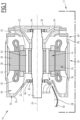
Figure 1 is a schematic, cross-sectional view of a vehicle comprising an electric traction motor according to an embodiment of the invention. -
Figure 1 shows anelectric traction motor 10 according to an embodiment of the invention. In a preferred embodiment, themotor 10 is an asynchronous motor. In another embodiment, the motor is a synchronous motor. - Preferably, the
motor 10 is a traction motor of a railway vehicle. More preferably, themotor 10 is assembled to abody 11 of the railway vehicle, in particular to a bogie. - As shown on
Figure 1 , themotor 10 comprises : amotor shaft 12 ; arotor 14, astator 16 and amotor frame 18. - The
motor shaft 12 extends along amain axis 20. In the embodiment ofFigure 1 , themain axis 20 extends horizontally. - The
rotor 14 extends around themotor shaft 12 and is fixed to saidmotor shaft 12. Therotor 14 extends axially between a first 22 and a second 23 ends. Therotor 14 includes at least oneventilation channel 24, extending parallel to themain axis 20 and opening on each of theends said rotor 14. - Preferably, the
rotor 14 includes a plurality ofventilation channels 24, arranged around themain axis 20. More preferably, a number ofventilation channels 24 is comprised between two and fifty. - In an embodiment, the
rotor 14 comprises metal laminations inserted around themotor shaft 12 and piled along themain axis 20. The laminations have notches and are crossed from end to end by copper bars which are all brazed on each side to a short circuit ring, so as to form a squirrel cage rotor. - The
stator 16 comprises astator core 26 of tubular shape, coaxial with themain axis 20. Thestator core 26 defines a cylindricalinner space 28, extending along themain axis 20 and enclosing therotor 14. - In the embodiment of
Figure 1 , thestator 16 also compriseswinding coils 30 inserted in thestator core 26. Thewinding coils 30 extend outside of the cylindricalinner space 28. - In the embodiment of
Figure 1 , themotor frame 18 comprises amain part 32 and a first 34 and a second 36 flanges. Themain part 32 comprises a substantially cylindricalinner surface 38, extending along themain axis 20 and fixed to thestator 16. - The first 34 and second 36 flanges are fixed respectively to a first end and to a second end of the
main part 32. Themotor frame 18, more precisely themain part 32 and the first 34 and second 36 flanges, define aninner compartment 40 enclosing therotor 14 and thestator 16. The first 34 and second 36 flanges face respectively the first 22 and second 23 ends of therotor 14. - The
motor shaft 12 is able to rotate relative to themotor frame 18 around themain axis 20. In the embodiment ofFigure 1 , themotor 10 comprisesbearing assemblies motor shaft 12 relative to the first 34 and second 36 flanges. Thefirst flange 34 comprises anaxial opening 46 from which an end of themotor shaft 12 protrudes axially. Preferably, said end of themotor shaft 12 is connected to a reduction gear (not shown). - The
motor 10 also comprisesair vents motor frame 18, opening on theinner compartment 40 and allowing passage for an air flux through the at least oneventilation channel 24 of therotor 14. In the embodiment ofFigure 1 , both the first 34 and second 36 flanges compriseair vents air vents - Preferably, the
motor 10 also comprises afan 54 fixed to themotor shaft 12 and enclosed in themotor frame 18, saidfan 54 being able to generate the air flux through the at least oneventilation channel 24 of the rotor. In the embodiment ofFigure 1 , thefan 54 is received in theinner compartment 40, between therotor 14 and thesecond flange 36. - The
motor 10 also comprises afirst aperture 56 formed in themotor frame 18. Thefirst aperture 56 is included in the cylindricalinner space 28, defined by thestator 16 around themain axis 20. In other terms, thefirst aperture 56 is substantially aligned with therotor 14 parallel to themain axis 20. - Preferably, the
first aperture 56 is arranged in one of the first 34 and second 36 flanges. More preferably, thefirst aperture 56 is situated opposite thefan 54, relative to therotor 14. In the embodiment ofFigure 1 , thefirst aperture 56 is arranged in thefirst flange 34. - As detailed below, the dimensions of the
first aperture 56 are preferably selected for allowing the introduction of anendoscopic device 58, or a cleaning device, in theinner compartment 40. - Preferably, the
motor 10 also comprises afirst cover 59, reversibly coupled to thefirst aperture 56. In a closed configuration, shown onFigure 1 , thefirst cover 59 is assembled to themotor frame 18 so as to close thefirst aperture 56. In an open configuration (not shown), thefirst cover 59 is dissociated from themotor frame 18 and thefirst aperture 56 is open. - In the embodiment of
Figure 1 , thefirst aperture 56 comprises aconcave surface 60 formed in thefirst flange 34. Preferably, theconcave surface 60 is substantially cylindrical. Thefirst cover 59 is a plug comprising aconvex surface 62 complementary with theconcave surface 60. In the closed configuration, theplug 59 is inserted in thefirst aperture 56 and the concave 60 and convex 62 surfaces are in contact with each other. - In other embodiments, the first cover is a hatch, articulated to the first 34 or second 36 flange ; or the first cover comprises a fastener for being reversibly assembled to the first aperture.
- Preferably, the
motor 10 also comprises asecond aperture 64 formed in themotor frame 18. More preferably, thesecond aperture 64 is situated at a bottom end of theinner compartment 40. - Preferably, the
second aperture 64 is situated opposite thefirst aperture 56, relative to therotor 14. In the embodiment ofFigure 1 , thesecond aperture 64 is arranged in thesecond flange 36. In another embodiment, the second aperture can also be arranged in themain part 32. - As detailed below, the dimensions of the
second aperture 64 are preferably selected for allowing access to theinner compartment 40 so as to remove dirt and dust. - Preferably, the
motor 10 also comprises asecond cover 66, reversibly coupled to thesecond aperture 64, between an open configuration and a closed configuration of saidsecond aperture 64. In the embodiment ofFigure 1 , thesecond cover 66 is a hatch, articulated to thesecond flange 36. - In other embodiments, the
second aperture 64 and cover 66 have a similar shape of concave surface and plug, as described above for the first aperture and cover ; or the second cover comprises a fastener for being reversibly assembled to the first aperture. - A method for implementing the
motor 10 will now be described. During a rotation of therotor 14 and of themotor shaft 12, an air flow is generated in theventilation channels 24 by the rotation of thefan 54. The air flow ensures a cooling of therotor 14 during operation of themotor 10. - Preferably, during the working of the
motor 10, the first 56 and second 64 apertures are in the closed configuration and the air flow passes through the air vents 50, 52. - When the
motor 10 is not working, in order to clean theventilation channels 24 of therotor 14, thefirst cover 59 is removed from thefirst aperture 56. Theendoscopic device 58 is introduced in theinner compartment 40 through said first aperture. Theendoscopic device 58 comprises a camera allowing an operator to visualize the inside of the inner compartment. - The
rotor 14 is manually rotated so as to substantially align one of theventilation channels 24 with thefirst aperture 56. Therefore, it is possible to introduce theendoscopic device 58 in saidventilation channel 24 for inspection. The operation may be repeated for eachventilation channel 24 of the rotor. - Then, if the
endoscopic device 58 allows to determine that theventilation channels 24 are coated with dirt or dust, saidventilation channels 24 are cleaned, for example by introducing an air nozzle (not shown) in thefirst aperture 56 and then in saidventilation channel 24, and by blowing air. The dirt or dust is ejected from theventilation channel 24 at thesecond end 23 of therotor 14. Said dirt or dust falls on the bottom end of theinner compartment 40, near thesecond aperture 64. - After the cleaning of one or
more ventilation channels 24 of the rotor, thesecond cover 66 is removed. The dirt or dust, fallen on the bottom end of theinner compartment 40, is then evacuated, for example by introducing an air sucker (not shown) in theinner compartment 40 through thesecond aperture 64. - The
motor 10 according to the invention allows the inspection and cleaning of theventilation channels 24 of the rotor, without dismounting theflanges main part 32 of themotor frame 18, and without dissociating themotor 10 from thebogie 11 of the vehicle. The maintenance of themotor 10 is therefore greatly simplified in comparison with the prior art.
Claims (9)
- An electric traction motor (10) comprising :- a motor shaft (12) extending along a main axis (20) ;- a rotor (14) extending around the motor shaft (12) and fixed to said motor shaft (12), the rotor (14) including at least one ventilation channel (24) extending substantially parallel to the main axis ;- a stator (16) coupled to the rotor (14), the stator (16) defining a cylindrical inner space (28), extending along the main axis (20) and enclosing the rotor (14) ;- a motor frame (18) fixed to the stator (16) and enclosing the rotor (14) and the stator (16), the motor shaft (12) being able to rotate relative to the motor frame (18) around the main axis (20); and- air vents (50, 52) opening on the motor frame (18) and allowing passage for an air flux through the at least one ventilation channel (24) of the rotor (14) ;the electric traction motor (10) being characterized in that it also comprises a first aperture (56) formed in the motor frame (18), the first aperture (56) being included in the cylindrical inner space (28) defined by the stator (16).
- An electric traction motor (10) according to claim 1, also comprising a first cover (59) reversibly coupled to the first aperture (56), between an open configuration and a closed configuration of said first aperture (56).
- An electric traction motor (10) according to claim 2, wherein the first aperture (56) comprises a concave surface (60) and the first cover (59) is a plug comprising a convex surface (62), so that, in the closed configuration, the plug is inserted in the first aperture (56) and the concave (60) and convex (62) surfaces are in contact with each other.
- An electric traction motor (10) according to any one of the previous claims, also comprising a second aperture (64) formed in the motor frame (18).
- An electric traction motor (10) according to claim 4, also comprising a second cover (66) reversibly coupled to the second aperture (64), between an open configuration and a closed configuration of said second aperture (64).
- An electric traction motor (10) according to claim 5, wherein the second cover (66) is a hatch, articulated to the motor frame (18).
- An electric traction motor (10) according to any one of the previous claims, also comprising a fan (54) fixed to the motor shaft (12) and enclosed in the motor frame (18), said fan (54) being able to generate the air flux through the at least one ventilation channel (24) of the rotor (14).
- A vehicle comprising a body (11) and an electric traction motor (10) according to one of the previous claims, assembled to said body (11).
- A vehicle according to claim 8 taken in combination with one of claims 4 to 6, wherein the main axis (20) of the motor shaft (12) is disposed horizontally and wherein the second aperture (64) is disposed at a bottom end of the motor frame (18).
Priority Applications (2)
| Application Number | Priority Date | Filing Date | Title |
|---|---|---|---|
| EP23306236.3A EP4496189A1 (en) | 2023-07-18 | 2023-07-18 | Electric traction motor for a vehicle |
| US18/775,255 US20250030293A1 (en) | 2023-07-18 | 2024-07-17 | Electric traction motor for a vehicle |
Applications Claiming Priority (1)
| Application Number | Priority Date | Filing Date | Title |
|---|---|---|---|
| EP23306236.3A EP4496189A1 (en) | 2023-07-18 | 2023-07-18 | Electric traction motor for a vehicle |
Publications (1)
| Publication Number | Publication Date |
|---|---|
| EP4496189A1 true EP4496189A1 (en) | 2025-01-22 |
Family
ID=87553541
Family Applications (1)
| Application Number | Title | Priority Date | Filing Date |
|---|---|---|---|
| EP23306236.3A Pending EP4496189A1 (en) | 2023-07-18 | 2023-07-18 | Electric traction motor for a vehicle |
Country Status (2)
| Country | Link |
|---|---|
| US (1) | US20250030293A1 (en) |
| EP (1) | EP4496189A1 (en) |
Citations (7)
| Publication number | Priority date | Publication date | Assignee | Title |
|---|---|---|---|---|
| JP2006005990A (en) * | 2004-06-15 | 2006-01-05 | Toshiba Corp | Vehicle drive motor |
| EP1100184B1 (en) * | 1999-11-09 | 2007-12-19 | Alstom | Motor ventilating device and electric traction motor provided with this device |
| WO2008022108A2 (en) | 2006-08-15 | 2008-02-21 | Bombardier Transportation Gmbh | Semi-enclosed ac motor |
| WO2011004451A1 (en) * | 2009-07-06 | 2011-01-13 | 三菱電機株式会社 | Electric motor for vehicle |
| US20160105069A1 (en) * | 2014-10-10 | 2016-04-14 | Fanuc Corporation | Motor having air path of stator, or fan cleanable, and cleaning system of motor |
| EP2605380B1 (en) * | 2011-12-15 | 2019-02-20 | Hitachi, Ltd. | Rotating electric machine, rail vehicle and electric vehicle equipped therewith |
| EP4060871A1 (en) * | 2021-03-19 | 2022-09-21 | Kabushiki Kaisha Toshiba | Rotary electric machine |
Family Cites Families (8)
| Publication number | Priority date | Publication date | Assignee | Title |
|---|---|---|---|---|
| WO2016189886A1 (en) * | 2015-05-28 | 2016-12-01 | 三菱電機株式会社 | Rotating electric machine |
| FR3036882B1 (en) * | 2015-05-28 | 2018-08-10 | Alstom Transport Technologies | STATOR COMPRISING AN INTEGRATED RADIATOR |
| FR3062757B1 (en) * | 2017-02-03 | 2019-04-05 | Alstom Transport Technologies | SILENT SELF-VENTILATED MOTOR, IN PARTICULAR FOR A RAILWAY VEHICLE |
| WO2019123658A1 (en) * | 2017-12-22 | 2019-06-27 | 本田技研工業株式会社 | Prime mover of work machine |
| JP7093745B2 (en) * | 2019-05-17 | 2022-06-30 | 本田技研工業株式会社 | Rotor structure of electric motor |
| US11715988B2 (en) * | 2020-04-08 | 2023-08-01 | Abb Schweiz Ag | System and methods for multiple configurations to cool an electric motor |
| WO2022137416A1 (en) * | 2020-12-24 | 2022-06-30 | 三菱電機株式会社 | Electric motor |
| DE102022131228B4 (en) * | 2022-11-25 | 2025-03-27 | Bühler Motor GmbH | Liquid pump with optimized cooling and heat dissipation |
-
2023
- 2023-07-18 EP EP23306236.3A patent/EP4496189A1/en active Pending
-
2024
- 2024-07-17 US US18/775,255 patent/US20250030293A1/en active Pending
Patent Citations (7)
| Publication number | Priority date | Publication date | Assignee | Title |
|---|---|---|---|---|
| EP1100184B1 (en) * | 1999-11-09 | 2007-12-19 | Alstom | Motor ventilating device and electric traction motor provided with this device |
| JP2006005990A (en) * | 2004-06-15 | 2006-01-05 | Toshiba Corp | Vehicle drive motor |
| WO2008022108A2 (en) | 2006-08-15 | 2008-02-21 | Bombardier Transportation Gmbh | Semi-enclosed ac motor |
| WO2011004451A1 (en) * | 2009-07-06 | 2011-01-13 | 三菱電機株式会社 | Electric motor for vehicle |
| EP2605380B1 (en) * | 2011-12-15 | 2019-02-20 | Hitachi, Ltd. | Rotating electric machine, rail vehicle and electric vehicle equipped therewith |
| US20160105069A1 (en) * | 2014-10-10 | 2016-04-14 | Fanuc Corporation | Motor having air path of stator, or fan cleanable, and cleaning system of motor |
| EP4060871A1 (en) * | 2021-03-19 | 2022-09-21 | Kabushiki Kaisha Toshiba | Rotary electric machine |
Also Published As
| Publication number | Publication date |
|---|---|
| US20250030293A1 (en) | 2025-01-23 |
Similar Documents
| Publication | Publication Date | Title |
|---|---|---|
| CN108808986B (en) | Electric motor | |
| DE60037496T2 (en) | Ventilation device and electric traction traction motor equipped with such a device | |
| CN102783001B (en) | electric motor | |
| EP0291918A2 (en) | Motor ventilation improvement | |
| EP3332470B1 (en) | Air-cooled electric motor with a parallel circuit of two fan wheels | |
| JP4433013B2 (en) | Vehicle alternator | |
| WO2012106159A2 (en) | System and method for increasing airflow in electric machines | |
| US20250030293A1 (en) | Electric traction motor for a vehicle | |
| JP4592825B1 (en) | Electric motor for vehicle | |
| DE102017005812B4 (en) | ELECTRIC MOTOR AND MACHINE TOOL EQUIPPED WITH THE ELECTRIC MOTOR | |
| US1820531A (en) | Dynamo-electric machine construction | |
| EP1798421B1 (en) | High-pressure ventilator | |
| EP0849858B1 (en) | Electric air-cooled machine | |
| Yung | Cool facts about cooling electric motors: improvements in applications that fall outside the normal operating conditions | |
| JP3162455B2 (en) | Induction motor | |
| JP2003023754A (en) | Fully enclosed fan motor | |
| JPH05344682A (en) | Outer rotor motor | |
| Yung | Cool facts about cooling electric motors | |
| JPH05336702A (en) | Induction motor | |
| US2202622A (en) | Self-cleaning textile motor | |
| EP3990793B1 (en) | Oil-evacuated electrical machine having rolling bearings, for a motor vehicle | |
| JP2014171388A (en) | Motor | |
| US20250015664A1 (en) | Deflector cover for rotating electric machine, modular sets for deflector covers, corresponding rotating electric machine and methods of converting the ventilation mode of a rotating electric machine | |
| US20250357820A1 (en) | Electric traction motor for a vehicle, with a cooling device | |
| EP0556589A1 (en) | Universal electromotor |
Legal Events
| Date | Code | Title | Description |
|---|---|---|---|
| PUAI | Public reference made under article 153(3) epc to a published international application that has entered the european phase |
Free format text: ORIGINAL CODE: 0009012 |
|
| STAA | Information on the status of an ep patent application or granted ep patent |
Free format text: STATUS: THE APPLICATION HAS BEEN PUBLISHED |
|
| STAA | Information on the status of an ep patent application or granted ep patent |
Free format text: STATUS: REQUEST FOR EXAMINATION WAS MADE |
|
| AK | Designated contracting states |
Kind code of ref document: A1 Designated state(s): AL AT BE BG CH CY CZ DE DK EE ES FI FR GB GR HR HU IE IS IT LI LT LU LV MC ME MK MT NL NO PL PT RO RS SE SI SK SM TR |
|
| 17P | Request for examination filed |
Effective date: 20250109 |