EP4496139A1 - Connector assembly and method of assembling such a connector assembly - Google Patents
Connector assembly and method of assembling such a connector assembly Download PDFInfo
- Publication number
- EP4496139A1 EP4496139A1 EP24187357.9A EP24187357A EP4496139A1 EP 4496139 A1 EP4496139 A1 EP 4496139A1 EP 24187357 A EP24187357 A EP 24187357A EP 4496139 A1 EP4496139 A1 EP 4496139A1
- Authority
- EP
- European Patent Office
- Prior art keywords
- connector
- counter
- securing
- support
- onto
- Prior art date
- Legal status (The legal status is an assumption and is not a legal conclusion. Google has not performed a legal analysis and makes no representation as to the accuracy of the status listed.)
- Granted
Links
Images

Classifications
-
- H—ELECTRICITY
- H01—ELECTRIC ELEMENTS
- H01R—ELECTRICALLY-CONDUCTIVE CONNECTIONS; STRUCTURAL ASSOCIATIONS OF A PLURALITY OF MUTUALLY-INSULATED ELECTRICAL CONNECTING ELEMENTS; COUPLING DEVICES; CURRENT COLLECTORS
- H01R13/00—Details of coupling devices of the kinds covered by groups H01R12/70 or H01R24/00 - H01R33/00
- H01R13/62—Means for facilitating engagement or disengagement of coupling parts or for holding them in engagement
- H01R13/621—Bolt, set screw or screw clamp
- H01R13/6215—Bolt, set screw or screw clamp using one or more bolts
-
- H—ELECTRICITY
- H01—ELECTRIC ELEMENTS
- H01R—ELECTRICALLY-CONDUCTIVE CONNECTIONS; STRUCTURAL ASSOCIATIONS OF A PLURALITY OF MUTUALLY-INSULATED ELECTRICAL CONNECTING ELEMENTS; COUPLING DEVICES; CURRENT COLLECTORS
- H01R13/00—Details of coupling devices of the kinds covered by groups H01R12/70 or H01R24/00 - H01R33/00
- H01R13/73—Means for mounting coupling parts to apparatus or structures, e.g. to a wall
- H01R13/74—Means for mounting coupling parts in openings of a panel
- H01R13/748—Means for mounting coupling parts in openings of a panel using one or more screws
-
- H—ELECTRICITY
- H01—ELECTRIC ELEMENTS
- H01R—ELECTRICALLY-CONDUCTIVE CONNECTIONS; STRUCTURAL ASSOCIATIONS OF A PLURALITY OF MUTUALLY-INSULATED ELECTRICAL CONNECTING ELEMENTS; COUPLING DEVICES; CURRENT COLLECTORS
- H01R13/00—Details of coupling devices of the kinds covered by groups H01R12/70 or H01R24/00 - H01R33/00
- H01R13/40—Securing contact members in or to a base or case; Insulating of contact members
-
- H—ELECTRICITY
- H01—ELECTRIC ELEMENTS
- H01R—ELECTRICALLY-CONDUCTIVE CONNECTIONS; STRUCTURAL ASSOCIATIONS OF A PLURALITY OF MUTUALLY-INSULATED ELECTRICAL CONNECTING ELEMENTS; COUPLING DEVICES; CURRENT COLLECTORS
- H01R13/00—Details of coupling devices of the kinds covered by groups H01R12/70 or H01R24/00 - H01R33/00
- H01R13/46—Bases; Cases
- H01R13/52—Dustproof, splashproof, drip-proof, waterproof, or flameproof cases
- H01R13/5202—Sealing means between parts of housing or between housing part and a wall, e.g. sealing rings
-
- H—ELECTRICITY
- H01—ELECTRIC ELEMENTS
- H01R—ELECTRICALLY-CONDUCTIVE CONNECTIONS; STRUCTURAL ASSOCIATIONS OF A PLURALITY OF MUTUALLY-INSULATED ELECTRICAL CONNECTING ELEMENTS; COUPLING DEVICES; CURRENT COLLECTORS
- H01R13/00—Details of coupling devices of the kinds covered by groups H01R12/70 or H01R24/00 - H01R33/00
- H01R13/62—Means for facilitating engagement or disengagement of coupling parts or for holding them in engagement
- H01R13/621—Bolt, set screw or screw clamp
-
- H—ELECTRICITY
- H01—ELECTRIC ELEMENTS
- H01R—ELECTRICALLY-CONDUCTIVE CONNECTIONS; STRUCTURAL ASSOCIATIONS OF A PLURALITY OF MUTUALLY-INSULATED ELECTRICAL CONNECTING ELEMENTS; COUPLING DEVICES; CURRENT COLLECTORS
- H01R13/00—Details of coupling devices of the kinds covered by groups H01R12/70 or H01R24/00 - H01R33/00
- H01R13/62—Means for facilitating engagement or disengagement of coupling parts or for holding them in engagement
- H01R13/622—Screw-ring or screw-casing
-
- H—ELECTRICITY
- H01—ELECTRIC ELEMENTS
- H01R—ELECTRICALLY-CONDUCTIVE CONNECTIONS; STRUCTURAL ASSOCIATIONS OF A PLURALITY OF MUTUALLY-INSULATED ELECTRICAL CONNECTING ELEMENTS; COUPLING DEVICES; CURRENT COLLECTORS
- H01R13/00—Details of coupling devices of the kinds covered by groups H01R12/70 or H01R24/00 - H01R33/00
- H01R13/62—Means for facilitating engagement or disengagement of coupling parts or for holding them in engagement
- H01R13/639—Additional means for holding or locking coupling parts together, after engagement, e.g. separate keylock, retainer strap
-
- H—ELECTRICITY
- H01—ELECTRIC ELEMENTS
- H01R—ELECTRICALLY-CONDUCTIVE CONNECTIONS; STRUCTURAL ASSOCIATIONS OF A PLURALITY OF MUTUALLY-INSULATED ELECTRICAL CONNECTING ELEMENTS; COUPLING DEVICES; CURRENT COLLECTORS
- H01R24/00—Two-part coupling devices, or either of their cooperating parts, characterised by their overall structure
-
- H—ELECTRICITY
- H01—ELECTRIC ELEMENTS
- H01R—ELECTRICALLY-CONDUCTIVE CONNECTIONS; STRUCTURAL ASSOCIATIONS OF A PLURALITY OF MUTUALLY-INSULATED ELECTRICAL CONNECTING ELEMENTS; COUPLING DEVICES; CURRENT COLLECTORS
- H01R24/00—Two-part coupling devices, or either of their cooperating parts, characterised by their overall structure
- H01R24/28—Coupling parts carrying pins, blades or analogous contacts and secured only to wire or cable
-
- H—ELECTRICITY
- H01—ELECTRIC ELEMENTS
- H01R—ELECTRICALLY-CONDUCTIVE CONNECTIONS; STRUCTURAL ASSOCIATIONS OF A PLURALITY OF MUTUALLY-INSULATED ELECTRICAL CONNECTING ELEMENTS; COUPLING DEVICES; CURRENT COLLECTORS
- H01R24/00—Two-part coupling devices, or either of their cooperating parts, characterised by their overall structure
- H01R24/76—Two-part coupling devices, or either of their cooperating parts, characterised by their overall structure with sockets, clips or analogous contacts and secured to apparatus or structure, e.g. to a wall
-
- H—ELECTRICITY
- H01—ELECTRIC ELEMENTS
- H01R—ELECTRICALLY-CONDUCTIVE CONNECTIONS; STRUCTURAL ASSOCIATIONS OF A PLURALITY OF MUTUALLY-INSULATED ELECTRICAL CONNECTING ELEMENTS; COUPLING DEVICES; CURRENT COLLECTORS
- H01R43/00—Apparatus or processes specially adapted for manufacturing, assembling, maintaining, or repairing of line connectors or current collectors or for joining electric conductors
-
- H—ELECTRICITY
- H01—ELECTRIC ELEMENTS
- H01R—ELECTRICALLY-CONDUCTIVE CONNECTIONS; STRUCTURAL ASSOCIATIONS OF A PLURALITY OF MUTUALLY-INSULATED ELECTRICAL CONNECTING ELEMENTS; COUPLING DEVICES; CURRENT COLLECTORS
- H01R43/00—Apparatus or processes specially adapted for manufacturing, assembling, maintaining, or repairing of line connectors or current collectors or for joining electric conductors
- H01R43/26—Apparatus or processes specially adapted for manufacturing, assembling, maintaining, or repairing of line connectors or current collectors or for joining electric conductors for engaging or disengaging the two parts of a coupling device
-
- F—MECHANICAL ENGINEERING; LIGHTING; HEATING; WEAPONS; BLASTING
- F16—ENGINEERING ELEMENTS AND UNITS; GENERAL MEASURES FOR PRODUCING AND MAINTAINING EFFECTIVE FUNCTIONING OF MACHINES OR INSTALLATIONS; THERMAL INSULATION IN GENERAL
- F16B—DEVICES FOR FASTENING OR SECURING CONSTRUCTIONAL ELEMENTS OR MACHINE PARTS TOGETHER, e.g. NAILS, BOLTS, CIRCLIPS, CLAMPS, CLIPS OR WEDGES; JOINTS OR JOINTING
- F16B35/00—Screw-bolts; Stay-bolts; Screw-threaded studs; Screws; Set screws
- F16B35/04—Screw-bolts; Stay-bolts; Screw-threaded studs; Screws; Set screws with specially-shaped head or shaft in order to fix the bolt on or in an object
- F16B35/041—Specially-shaped shafts
- F16B35/044—Specially-shaped ends
- F16B35/045—Specially-shaped ends for retention or rotation by a tool
-
- F—MECHANICAL ENGINEERING; LIGHTING; HEATING; WEAPONS; BLASTING
- F16—ENGINEERING ELEMENTS AND UNITS; GENERAL MEASURES FOR PRODUCING AND MAINTAINING EFFECTIVE FUNCTIONING OF MACHINES OR INSTALLATIONS; THERMAL INSULATION IN GENERAL
- F16B—DEVICES FOR FASTENING OR SECURING CONSTRUCTIONAL ELEMENTS OR MACHINE PARTS TOGETHER, e.g. NAILS, BOLTS, CIRCLIPS, CLAMPS, CLIPS OR WEDGES; JOINTS OR JOINTING
- F16B5/00—Joining sheets or plates, e.g. panels, to one another or to strips or bars parallel to them
- F16B5/02—Joining sheets or plates, e.g. panels, to one another or to strips or bars parallel to them by means of fastening members using screw-thread
- F16B5/0275—Joining sheets or plates, e.g. panels, to one another or to strips or bars parallel to them by means of fastening members using screw-thread the screw-threaded element having at least two axially separated threaded portions
-
- H—ELECTRICITY
- H01—ELECTRIC ELEMENTS
- H01R—ELECTRICALLY-CONDUCTIVE CONNECTIONS; STRUCTURAL ASSOCIATIONS OF A PLURALITY OF MUTUALLY-INSULATED ELECTRICAL CONNECTING ELEMENTS; COUPLING DEVICES; CURRENT COLLECTORS
- H01R2105/00—Three poles
-
- H—ELECTRICITY
- H01—ELECTRIC ELEMENTS
- H01R—ELECTRICALLY-CONDUCTIVE CONNECTIONS; STRUCTURAL ASSOCIATIONS OF A PLURALITY OF MUTUALLY-INSULATED ELECTRICAL CONNECTING ELEMENTS; COUPLING DEVICES; CURRENT COLLECTORS
- H01R2201/00—Connectors or connections adapted for particular applications
- H01R2201/26—Connectors or connections adapted for particular applications for vehicles
Definitions
- This disclosure relates to the field of automotive connectors and, for example, to the field of power connectors for automotive applications.
- connector assemblies comprising a connector (e.g., a header) and a counter-connector (e.g. a plug) to be mated to the connector, wherein the connector has a housing configured to be mounted to a support such as an appliance, a structural element of a vehicle, etc.. Then, one or several screws may be used to secure the housing to its support, and another screw or several other screws may be used to secure the connector to the counter-connector.
- a connector e.g., a header
- a counter-connector e.g. a plug
- Assembling these connectors therefore generally involves placing and screwing the connector onto its support, then placing and screwing the counter-connector onto the connector and/or the support.
- This type of connector assembly has drawbacks. For example, the room taken up by all the screws requires relatively large connector housings. Accordingly, there is a need for improving at least partially such connector assemblies and their assembly and mounting processes onto a support.
- a connector assembly according to claim 1 is described below, which at least partially helps to overcome at least some of the drawbacks of the prior art.
- a same securing member (or fastening element) is used to both secure the connector onto the support and to secure the counter-connector onto the connector. Therefore, instead of providing enough room in the connector for two different fastening elements (e.g., two different screws), i.e., one to secure the connector onto the support and one to secure the counter-connector onto the connector, it is sufficient to provide room for only one single fastening element.
- two securing members can be used for securing the connector, the counter-connector and the support together, but at least one securing member may replace two fastening elements.
- This connector also optionally comprises one and/or other of the features mentioned in claims 2 to 10, each considered independently of the other or in combination with one or more others.
- FIG. 1 An example embodiment of a connector 1 is shown in Figure 1 .
- This connector 1 is used for example in an electrical power circuit of a motor vehicle.
- Such a circuit is used, for example, to interconnect components such as a connection bar, a battery, a charging station, a converter, an electric motor, etc.
- the connector 1 is a header.
- the connector 1 comprises a connector housing 2.
- the connector housing 2 accommodates three power terminals 3 (at least one of these power terminals 3 corresponds to said "at least one first electrical terminal recited in the claims).
- each power terminal 3 is protected by a cap 4.
- the housing 2 and the caps 4 are made, for example, of molded plastics (dielectric plastics).
- the power terminals 3 are made, for example, of a copper alloy (alternatively they are made of aluminium alloy or of another conductive material).
- the housing 2 is secured onto a support 5 with the help of two screws 6 and one securing member 7.
- the number of screws 6 and/or securing member 7 may vary.
- the screws 6 are made, for example, of steel zinc-nickel plated.
- the securing member 7 is made, for example, of steel zinc-nickel plated.
- the securing member 7 is essentially positioned in a triangular area 12 left free between the three protection caps 4. In other words, the securing member 7 does not take up extra space in the connector 1, which would otherwise have required an increase of the size of the connector housing 2.
- the securing member 7 passes through a cylindrical passage 18 provided through a plate 19 of the connector housing 2. More particularly, the securing member 7 passes through a cylindrical standoff ring 20 inserted in the cylindrical passage 18.
- the cylindrical standoff ring 20 is made of metal. Since the connector housing 2 is made of plastics, the cylindrical standoff ring 20 provides a reinforcement that prevents the housing plate 19 from breaking when the securing member 7 clamps the connector 1 onto the support 5.
- the securing member 7 comprises a first securing section 8 configured to secure the connector 1 onto the support 5.
- the first securing section 8 comprises a first threaded portion 9.
- the first threaded portion 9 is at least partially screwed into a complementary threaded hole 17 of the support 5.
- the first securing section 8 comprises any securing means which are adapted to secure the connector 1 to the support 5.
- such securing means can be configured to be inserted in force or press-fitted in a hole, to cooperate with a self-retaining ring, etc.
- the securing member 7 further comprises a second securing section 13.
- the second securing section 13 comprises a second threaded portion 14.
- the second securing section 13 comprises any securing means which are adapted to secure the connector 1 and a counter-connector 10 to each other.
- such securing means may consist of complementary snapping means, latching means, locking means, etc.
- the securing member 7 comprises a standoff section 15 between the first 8 and second 13 securing sections.
- the standoff section 15 comprises a nut section 30 configured to screw the securing member 7, in the support 5, on the plate 19.
- the nut section 30 can have any suitable shape for tightening the securing member 7 onto the support 5 (e.g., Hex or Torx compatible shape), the standoff section 15 comprises a ring section 16.
- the ring section 16 is configured to cooperate with the connector housing 2 (e.g., the plate 19 of the connector housing 2) to hold the connector 1 onto the support 5.
- the ring section 16 is formed as a single piece with the remaining sections 8, 15 and 13 of the securing member 7.
- the ring section 16 rests on the cylindrical standoff ring 20 and/or on an annular surface of the connector housing 2, which surrounds the cylindrical passage 18. In the illustrated example, this annular surface is itself surrounded by an annular rib 26.
- the rib 26 guides the ring section 16 and ensures a precise positioning of the connector 1 on the support 5.
- the rib 26 is also located above a seal 24 surrounding a region of the plate 19 comprising the terminals 3 of the connector 1. The rib 26 then acts as a reinforcing structure which ensures that the plate 19 is flat and that there is a good seal between the plate 19 and the support 5.
- the ring section 16 is thick enough (in direction parallel to the longitudinal direction of the securing member 7, which also corresponds to a securing direction SD when the assembly is performed) so that an alignment structure 29 of the counter-connector or plug 10 can be guided by the ring section 16, when the counter-connector 10 is mated with the connector 1 (see figure 4 ).
- the securing member 7 comprises a free end 21 located on a same side as the second threaded portion 14 (see figure 2 ).
- the free end 21 comprises a screwing structure 22 whose shape is complementary to that of a spanner or screwdriver.
- the securing member 7 extends longitudinally between two free ends and comprises from a free end to the other: the first threaded portion 9, an intermediate portion 25, the ring section 16, the standoff section 15, the second threaded portion 14 and the free end 21 comprising the screwing structure 22. All this portions and sections form a single piece. This provides the advantage of simplifying the assembly process of the connector 1 and the counter-connector 10 onto the support 5. This also simplifies the sourcing and supply chain logistics because there are less parts to manage.
- the counter-connector 10 is mounted on the connector 1.
- the counter-connector 10 comprises a counter-connector housing 11.
- the counter-connector 10 is a plug connector (e.g., a female connector).
- the counter-connector 10 is a cable connector. It accommodates three power terminals (not shown), each electrically and mechanically connected to a cable.
- the cables extend perpendicular to the mating direction.
- the cables are power cables with a relatively large section.
- the cables are relatively stiff and heavy.
- the counter-connector 10 comprises a hollow 23.
- the hollow 23 is essentially located in a region corresponding, in the connector 1, to the triangular area 12.
- a ring 31 is mounted on the counter-connector 10.
- the counter-connector 10 has retaining means 27 to retain the ring 31.
- the ring 31 has a rectangular plate-like shape configured to be guided when inserted onto the counter-connector 10.
- the ring 31 has an internal shape around a hole so as to enable the retention of a nut 28 on the ring 31 after a specific crimping.
- the retaining means 27 are flexibles so as to facilitate the insertion of the ring 31 and the nut 28 onto the counter-connector 10, in one direction (a chamfered portion helps the insertion), and so as to make it more difficult to remove it in the opposite direction.
- the retaining means 27 hold the ring 31 and the nut 28 captive. Therefore, the ring 31 and the nut 28 are mounted and held on the counter-connector 10.
- the counter-connector 10 is supplied at a harness maker (i.e., the manufacturer carrying out the assembly of the cables with the terminals, as well as the mounting of the terminals in the counter-connector 10). This is an advantage in that there is no risk of the nut 28 being lost. It also simplifies the supply chain, as there are fewer separate elements to manage.
- the nut 28 is screwed on the second threaded portion 14 and tightened on the ring 31 (alternatively any other appropriate fastening means may be used instead of the nut 28 and the threaded portion 14).
- the nut 28 and the ring 31 are located in the hollow 23 so that they do not clutter up the environment of the connector assembly 100.
- the standoff section 15 allows to block the ring 31 and the nut 28 and therefore prevents the connector housing 2 to be deformed and/or broken.
- the counter-connector 10 (with its cables, terminals, ring 31 and nut 18) can be prepared by a harness maker.
- the connector 1 can be directly supplied to car manufacturer.
- car manufacturer can be supplied with the connector 1 and the securing member 7 by the manufacturer of the connector 1 and can be supplied with the counter-connector 10 by a harness maker. The assembly of the connector 1 with the counter-connector 10 is then quite easy for the car manufacturer.
- the connector 1 and counter-connector 10 have complementary sliding means 50.
- the sliding means 50 acts as a "third hand”. Indeed, as the cables are stiff and heavy, the sliding means 50 helps maintaining the connector 1 and counter-connector 10 in a premating position before the above-mentioned screwing step and helps aligning the connector 1 and counter-connector 10 so as to ease the screwing and to avoid damaging the respective threads of the nut 28 and the second threaded portion 14.
Landscapes
- Engineering & Computer Science (AREA)
- Manufacturing & Machinery (AREA)
- Connector Housings Or Holding Contact Members (AREA)
- Details Of Connecting Devices For Male And Female Coupling (AREA)
Abstract
- the support (5) is configured to receive the connector (1),
- the connector (1) comprises a connector housing (2) to accommodate at least one first electrical terminal (3), and
- the counter-connector (10) is configured to mate the connector (1) and comprises a counter-connector housing (11) to accommodate at least one second electrical terminal configured to be connected to said at least one first electrical terminal (3), characterized in that said at least one securing member (7) comprises a first securing section (8) configured to secure the connector (1) onto the support (5) and a second securing section (13) configured to secure the counter-connector (10) onto the connector (1).
Description
- This disclosure relates to the field of automotive connectors and, for example, to the field of power connectors for automotive applications.
- There are connector assemblies comprising a connector (e.g., a header) and a counter-connector (e.g. a plug) to be mated to the connector, wherein the connector has a housing configured to be mounted to a support such as an appliance, a structural element of a vehicle, etc.. Then, one or several screws may be used to secure the housing to its support, and another screw or several other screws may be used to secure the connector to the counter-connector.
- Assembling these connectors therefore generally involves placing and screwing the connector onto its support, then placing and screwing the counter-connector onto the connector and/or the support. This type of connector assembly has drawbacks. For example, the room taken up by all the screws requires relatively large connector housings. Accordingly, there is a need for improving at least partially such connector assemblies and their assembly and mounting processes onto a support.
- A connector assembly according to
claim 1 is described below, which at least partially helps to overcome at least some of the drawbacks of the prior art. - Indeed, a same securing member (or fastening element) is used to both secure the connector onto the support and to secure the counter-connector onto the connector. Therefore, instead of providing enough room in the connector for two different fastening elements (e.g., two different screws), i.e., one to secure the connector onto the support and one to secure the counter-connector onto the connector, it is sufficient to provide room for only one single fastening element. Of course, several securing members can be used for securing the connector, the counter-connector and the support together, but at least one securing member may replace two fastening elements.
- This connector also optionally comprises one and/or other of the features mentioned in
claims 2 to 10, each considered independently of the other or in combination with one or more others. - Also described below is a method of assembling a connector assembly, according to
claims - Further features and advantages will become apparent in the detailed disclosure of an example embodiment of a connector assembly, as well as variations of this embodiment, this disclosure being accompanied by references to the accompanying drawings.
-
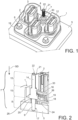
Figure 1 shows a schematic perspective view of an example of a connector secured to a support; -
Figure 2 shows schematically in perspective and in cross-section a portion of the connector and the support ofFigure 1 ; -
Figure 3 shows a schematic perspective view of a connector assembly comprising a counter-connector secured onto the connector and the support illustrated infigure 1 ; and -
Figure 4 shows schematically in perspective and in cross-section a portion of the connector assembly ofFigure 3 . - An example embodiment of a
connector 1 is shown inFigure 1 . Thisconnector 1 is used for example in an electrical power circuit of a motor vehicle. Such a circuit is used, for example, to interconnect components such as a connection bar, a battery, a charging station, a converter, an electric motor, etc. - In the illustrated example, the
connector 1 is a header. - The
connector 1 comprises aconnector housing 2. In this example, theconnector housing 2 accommodates three power terminals 3 (at least one of thesepower terminals 3 corresponds to said "at least one first electrical terminal recited in the claims). In the illustrated example, eachpower terminal 3 is protected by acap 4. Thehousing 2 and thecaps 4 are made, for example, of molded plastics (dielectric plastics). Thepower terminals 3 are made, for example, of a copper alloy (alternatively they are made of aluminium alloy or of another conductive material). - In this illustrated example, the
housing 2 is secured onto asupport 5 with the help of twoscrews 6 and one securingmember 7. In alternative embodiments, the number ofscrews 6 and/or securingmember 7 may vary. Thescrews 6 are made, for example, of steel zinc-nickel plated. The securingmember 7 is made, for example, of steel zinc-nickel plated. The securingmember 7 is essentially positioned in atriangular area 12 left free between the threeprotection caps 4. In other words, thesecuring member 7 does not take up extra space in theconnector 1, which would otherwise have required an increase of the size of theconnector housing 2. - As shown in
figure 2 , thesecuring member 7 passes through acylindrical passage 18 provided through aplate 19 of theconnector housing 2. More particularly, thesecuring member 7 passes through acylindrical standoff ring 20 inserted in thecylindrical passage 18. For example, thecylindrical standoff ring 20 is made of metal. Since theconnector housing 2 is made of plastics, thecylindrical standoff ring 20 provides a reinforcement that prevents thehousing plate 19 from breaking when the securingmember 7 clamps theconnector 1 onto thesupport 5. - The securing
member 7 comprises afirst securing section 8 configured to secure theconnector 1 onto thesupport 5. In the illustrated example, thefirst securing section 8 comprises a first threadedportion 9. The first threadedportion 9 is at least partially screwed into a complementary threadedhole 17 of thesupport 5. In alternative embodiments, thefirst securing section 8 comprises any securing means which are adapted to secure theconnector 1 to thesupport 5. For example, such securing means can be configured to be inserted in force or press-fitted in a hole, to cooperate with a self-retaining ring, etc. - The securing
member 7 further comprises a second securing section 13. In the illustrated example, the second securing section 13 comprises a second threadedportion 14. In alternative embodiments, the second securing section 13 comprises any securing means which are adapted to secure theconnector 1 and acounter-connector 10 to each other. For example, such securing means may consist of complementary snapping means, latching means, locking means, etc. - In the illustrated example, the
securing member 7 comprises astandoff section 15 between the first 8 and second 13 securing sections. In the illustrated example, thestandoff section 15 comprises anut section 30 configured to screw the securingmember 7, in thesupport 5, on theplate 19. Thenut section 30 can have any suitable shape for tightening the securingmember 7 onto the support 5 (e.g., Hex or Torx compatible shape), thestandoff section 15 comprises aring section 16. Thering section 16 is configured to cooperate with the connector housing 2 (e.g., theplate 19 of the connector housing 2) to hold theconnector 1 onto thesupport 5. Thering section 16 is formed as a single piece with theremaining sections member 7. Thering section 16 rests on thecylindrical standoff ring 20 and/or on an annular surface of theconnector housing 2, which surrounds thecylindrical passage 18. In the illustrated example, this annular surface is itself surrounded by anannular rib 26. Therib 26 guides thering section 16 and ensures a precise positioning of theconnector 1 on thesupport 5. Therib 26 is also located above aseal 24 surrounding a region of theplate 19 comprising theterminals 3 of theconnector 1. Therib 26 then acts as a reinforcing structure which ensures that theplate 19 is flat and that there is a good seal between theplate 19 and thesupport 5. - The
ring section 16 is thick enough (in direction parallel to the longitudinal direction of the securingmember 7, which also corresponds to a securing direction SD when the assembly is performed) so that analignment structure 29 of the counter-connector orplug 10 can be guided by thering section 16, when thecounter-connector 10 is mated with the connector 1 (seefigure 4 ). - The securing
member 7 comprises afree end 21 located on a same side as the second threaded portion 14 (seefigure 2 ). Thefree end 21 comprises ascrewing structure 22 whose shape is complementary to that of a spanner or screwdriver. - In summary, the
securing member 7 extends longitudinally between two free ends and comprises from a free end to the other: the first threadedportion 9, anintermediate portion 25, thering section 16, thestandoff section 15, the second threadedportion 14 and thefree end 21 comprising thescrewing structure 22. All this portions and sections form a single piece. This provides the advantage of simplifying the assembly process of theconnector 1 and the counter-connector 10 onto thesupport 5. This also simplifies the sourcing and supply chain logistics because there are less parts to manage. - As shown in
figure 3 , the counter-connector 10 is mounted on theconnector 1. The counter-connector 10 comprises acounter-connector housing 11. In the illustrated example, the counter-connector 10 is a plug connector (e.g., a female connector). The counter-connector 10 is a cable connector. It accommodates three power terminals (not shown), each electrically and mechanically connected to a cable. The cables extend perpendicular to the mating direction. The cables are power cables with a relatively large section. The cables are relatively stiff and heavy. - As shown in
figure 3 , the counter-connector 10 comprises a hollow 23. The hollow 23 is essentially located in a region corresponding, in theconnector 1, to thetriangular area 12. Aring 31 is mounted on the counter-connector 10. The counter-connector 10 has retaining means 27 to retain thering 31. For example, thering 31 has a rectangular plate-like shape configured to be guided when inserted onto the counter-connector 10. Thering 31 has an internal shape around a hole so as to enable the retention of anut 28 on thering 31 after a specific crimping. The retaining means 27 are flexibles so as to facilitate the insertion of thering 31 and thenut 28 onto the counter-connector 10, in one direction (a chamfered portion helps the insertion), and so as to make it more difficult to remove it in the opposite direction. The retaining means 27 hold thering 31 and thenut 28 captive. Therefore, thering 31 and thenut 28 are mounted and held on the counter-connector 10. For example, the counter-connector 10 is supplied at a harness maker (i.e., the manufacturer carrying out the assembly of the cables with the terminals, as well as the mounting of the terminals in the counter-connector 10). This is an advantage in that there is no risk of thenut 28 being lost. It also simplifies the supply chain, as there are fewer separate elements to manage. Thenut 28 is screwed on the second threadedportion 14 and tightened on the ring 31 (alternatively any other appropriate fastening means may be used instead of thenut 28 and the threaded portion 14). Thenut 28 and thering 31 are located in the hollow 23 so that they do not clutter up the environment of theconnector assembly 100. - As shown in
figure 4 , thestandoff section 15 allows to block thering 31 and thenut 28 and therefore prevents theconnector housing 2 to be deformed and/or broken. - On the one hand, as mentioned above, the counter-connector 10 (with its cables, terminals,
ring 31 and nut 18) can be prepared by a harness maker. - On the other hand, the
connector 1 can be directly supplied to car manufacturer. In other words, car manufacturer can be supplied with theconnector 1 and the securingmember 7 by the manufacturer of theconnector 1 and can be supplied with the counter-connector 10 by a harness maker. The assembly of theconnector 1 with the counter-connector 10 is then quite easy for the car manufacturer. - For assembling the
connector 1 and the counter-connector 10 on thesupport 5, the following steps are carried out: - placing the
connector 1 onto thesupport 5, - securing the
connector 1 onto thesupport 5 with the help of the securingmember 7 and thescrews 6, - placing the
connector 1 and the counter-connector 10 so that the terminals of theconnector 1 and the counter-connector 10 are aligned in a premating position, and so that the counter-connector 10 is in a position relative to the securingmember 7, which is adapted to engage thenut 28 on the securingmember 7, - screwing the
nut 28 on the second threadedportion 14 so as to clamp theconnector housing 2 and thecounter-connector housing 11 between thesupport 5 and thering 31. Screwing thenut 28 on the second threadedportion 14 assists the mating of theconnector 1 and counter-connector 10, and their respective terminals. - So as to help the
connector 1 and counter-connector 10 to be well aligned before and during screwing thenut 28 on the second threadedportion 14, theconnector 1 and counter-connector 10 have complementary slidingmeans 50. The sliding means 50 acts as a "third hand". Indeed, as the cables are stiff and heavy, the slidingmeans 50 helps maintaining theconnector 1 and counter-connector 10 in a premating position before the above-mentioned screwing step and helps aligning theconnector 1 and counter-connector 10 so as to ease the screwing and to avoid damaging the respective threads of thenut 28 and the second threadedportion 14.
Claims (12)
- A connector assembly (100) comprising a support (5), a connector (1), a counter-connector (10) and at least one securing member (7) extending longitudinally along a securing direction (SD), wherein- the support (5) is configured to receive the connector (1),- the connector (1) comprises a connector housing (2) to accommodate at least one first electrical terminal (3), and- the counter-connector (10) is configured to mate the connector (1) and comprises a counter-connector housing (11) to accommodate at least one second electrical terminal configured to be connected to said at least one first electrical terminal (3), characterized in that said at least one securing member (7) comprises a first securing section (8) configured to secure the connector (1) onto the support (5) and a second securing section (13) configured to secure the counter-connector (10) onto the connector (1).
- A connector assembly according to claim 1, wherein the first securing section (8) comprises a first threaded portion (9) configured to be screwed onto the support (5).
- A connector assembly according to claim 1 or 2, wherein the second securing section (13) comprises a second threaded portion (14) configured to be screwed with a nut (28) to hold the counter-connector (10) mated to the connector (1).
- A connector assembly according to any one of the preceding claims, wherein said at least one securing member (7) comprises a standoff section (15) between the first (8) and second (13) securing sections.
- A connector assembly according to claim 4, wherein the standoff section (15) comprises a nut section (30) forming a single piece with said at least one securing member (7).
- A connector assembly according to claim 5, wherein the standoff section (15) comprises a ring section (16) configured to cooperate with the connector (1) to hold the connector (1) onto the support (5), the ring section (16) forming a single piece with said at least one securing member (7).
- A connector assembly according to any one of the preceding claims, wherein said at least one securing member (7) comprises a free end (21) located on a same side as the second threaded portion (14), said free end (21) comprising a screwing structure (22) whose shape is complementary to that of a spanner or screwdriver.
- A connector assembly according to any one of the preceding claims, wherein the counter-connector (10) comprises retaining means (27) configured to retain a ring (26) on which a nut (28) is tightened when it is screwed onto the second threaded portion (14).
- A connector assembly according the claim 8, wherein the retaining means (27) hold the nut (28) captive.
- A connector assembly according to any one of the preceding claims, comprising a seal (24) inserted between the connector housing (2) and the support (5).
- A method of assembling a connector (1) and a counter-connector (10) with a support (5), comprising- placing the connector (1) onto the support (5),- securing the connector (1) onto the support (5) with the help of at least one securing member (7),- placing the connector (1) and the counter-connector (10) so that at least one first terminal (3) accommodated in the connector (1) and at least one second terminal accommodated in the counter-connector (10) are in a premating position, and so that the counter-connector (10) is in a position relative to said at least one securing member (7), which is adapted to engage a fastener (28) on said at least one securing member (7),- securing a first securing section (8) of said at least one securing member (7) onto the support (5) so as to secure the connector (1) onto the support (5) and securing the counter-connector (10) onto the connector (1) with the fastener (8) engaged onto a second securing section (13) of said at least one securing member (7).
- A method according to claim 11, wherein the fastener (28) is a nut and wherein said at least one first terminal (3) and said at least one second terminal are connected while the nut (28) is screwed on said at least one securing member (7).
Priority Applications (2)
| Application Number | Priority Date | Filing Date | Title |
|---|---|---|---|
| CN202410943008.5A CN119324335A (en) | 2023-07-15 | 2024-07-15 | Connector assembly and method of assembling such a connector assembly |
| US18/772,451 US20250023293A1 (en) | 2023-07-15 | 2024-07-15 | Connector assembly and method of assembling such a connector assembly |
Applications Claiming Priority (1)
| Application Number | Priority Date | Filing Date | Title |
|---|---|---|---|
| EP23185705 | 2023-07-15 |
Publications (2)
| Publication Number | Publication Date |
|---|---|
| EP4496139A1 true EP4496139A1 (en) | 2025-01-22 |
| EP4496139B1 EP4496139B1 (en) | 2025-10-29 |
Family
ID=87378183
Family Applications (1)
| Application Number | Title | Priority Date | Filing Date |
|---|---|---|---|
| EP24187357.9A Active EP4496139B1 (en) | 2023-07-15 | 2024-07-09 | Connector assembly and method of assembling such a connector assembly |
Country Status (3)
| Country | Link |
|---|---|
| US (1) | US20250023293A1 (en) |
| EP (1) | EP4496139B1 (en) |
| CN (1) | CN119324335A (en) |
Families Citing this family (1)
| Publication number | Priority date | Publication date | Assignee | Title |
|---|---|---|---|---|
| US12401160B2 (en) * | 2022-03-09 | 2025-08-26 | Tyco Electronics (Shanghai) Co., Ltd. | Connector and connector assembly |
Citations (2)
| Publication number | Priority date | Publication date | Assignee | Title |
|---|---|---|---|---|
| US20070177959A1 (en) * | 2006-01-27 | 2007-08-02 | Panduit Corp. | Data center cabinet bonding stud |
| DE102018222103A1 (en) * | 2017-12-20 | 2019-06-27 | Yazaki Corporation | Connector and electrical wire with connector |
-
2024
- 2024-07-09 EP EP24187357.9A patent/EP4496139B1/en active Active
- 2024-07-15 CN CN202410943008.5A patent/CN119324335A/en active Pending
- 2024-07-15 US US18/772,451 patent/US20250023293A1/en active Pending
Patent Citations (2)
| Publication number | Priority date | Publication date | Assignee | Title |
|---|---|---|---|---|
| US20070177959A1 (en) * | 2006-01-27 | 2007-08-02 | Panduit Corp. | Data center cabinet bonding stud |
| DE102018222103A1 (en) * | 2017-12-20 | 2019-06-27 | Yazaki Corporation | Connector and electrical wire with connector |
Also Published As
| Publication number | Publication date |
|---|---|
| EP4496139B1 (en) | 2025-10-29 |
| US20250023293A1 (en) | 2025-01-16 |
| CN119324335A (en) | 2025-01-17 |
Similar Documents
| Publication | Publication Date | Title |
|---|---|---|
| EP2586101B1 (en) | Electrical connection bus | |
| US9077114B2 (en) | Quick connect power connector | |
| EP2355260B1 (en) | Connector | |
| CN102239601B (en) | Connection assembly on circuit boards | |
| US20070128929A1 (en) | Wiring holding unit | |
| EP2701240B1 (en) | Method of assembly of an electrical connector | |
| US9705225B1 (en) | Electrical connector assembly having a plurality of electrical socket terminals retained within a socket cartridge | |
| US20240351457A1 (en) | Charging inlet assembly of a vehicle | |
| KR20190007068A (en) | Electrically conductive connection forming device | |
| EP4496139B1 (en) | Connector assembly and method of assembling such a connector assembly | |
| CN112106259A (en) | Plug-in connection element for a motor vehicle and method for producing such a plug-in connection element | |
| US8056867B2 (en) | Position assurance assembly for an electrical connector | |
| KR20150028966A (en) | Interconnection assembly for vehicle devices and method of interconnection | |
| US12479318B2 (en) | Charging inlet assembly having a power harness | |
| KR102782781B1 (en) | Insulators for screw contacts and crimp contacts | |
| JP2009506511A (en) | Busbar and connector | |
| WO2017077025A1 (en) | Vehicle earth point connector | |
| US20260039054A1 (en) | Bolt position assurance device for a power harness connector | |
| EP4052968B1 (en) | High voltage power distributor | |
| US12512563B2 (en) | Module connector and method for electrically conductively connecting a module connector to a battery module | |
| CN108987950B (en) | Terminal board for fixing electric wire and method for fixing electric wire on terminal board | |
| JP2011070850A (en) | Harness connector | |
| WO2013178434A1 (en) | Interconnection assembly for vehicle devices and method of interconnection | |
| KR200211522Y1 (en) | The battery post connecting terminal having a power dividing terminal | |
| JP2000067995A (en) | High-density multipolar connector |
Legal Events
| Date | Code | Title | Description |
|---|---|---|---|
| PUAI | Public reference made under article 153(3) epc to a published international application that has entered the european phase |
Free format text: ORIGINAL CODE: 0009012 |
|
| STAA | Information on the status of an ep patent application or granted ep patent |
Free format text: STATUS: THE APPLICATION HAS BEEN PUBLISHED |
|
| AK | Designated contracting states |
Kind code of ref document: A1 Designated state(s): AL AT BE BG CH CY CZ DE DK EE ES FI FR GB GR HR HU IE IS IT LI LT LU LV MC ME MK MT NL NO PL PT RO RS SE SI SK SM TR |
|
| STAA | Information on the status of an ep patent application or granted ep patent |
Free format text: STATUS: REQUEST FOR EXAMINATION WAS MADE |
|
| 17P | Request for examination filed |
Effective date: 20250409 |
|
| GRAP | Despatch of communication of intention to grant a patent |
Free format text: ORIGINAL CODE: EPIDOSNIGR1 |
|
| STAA | Information on the status of an ep patent application or granted ep patent |
Free format text: STATUS: GRANT OF PATENT IS INTENDED |
|
| GRAS | Grant fee paid |
Free format text: ORIGINAL CODE: EPIDOSNIGR3 |
|
| INTG | Intention to grant announced |
Effective date: 20250723 |
|
| RIN1 | Information on inventor provided before grant (corrected) |
Inventor name: GUILLANTON, MELANIE Inventor name: ZHAO, KED Inventor name: BHATTACHARJEE, TANURAJ Inventor name: MORIN, LAURENT |
|
| GRAA | (expected) grant |
Free format text: ORIGINAL CODE: 0009210 |
|
| STAA | Information on the status of an ep patent application or granted ep patent |
Free format text: STATUS: THE PATENT HAS BEEN GRANTED |
|
| AK | Designated contracting states |
Kind code of ref document: B1 Designated state(s): AL AT BE BG CH CY CZ DE DK EE ES FI FR GB GR HR HU IE IS IT LI LT LU LV MC ME MK MT NL NO PL PT RO RS SE SI SK SM TR |
|
| REG | Reference to a national code |
Ref country code: CH Ref legal event code: F10 Free format text: ST27 STATUS EVENT CODE: U-0-0-F10-F00 (AS PROVIDED BY THE NATIONAL OFFICE) Effective date: 20251029 Ref country code: GB Ref legal event code: FG4D |
|
| REG | Reference to a national code |
Ref country code: IE Ref legal event code: FG4D |
|
| REG | Reference to a national code |
Ref country code: DE Ref legal event code: R096 Ref document number: 602024001091 Country of ref document: DE |
|
| P01 | Opt-out of the competence of the unified patent court (upc) registered |
Free format text: CASE NUMBER: UPC_APP_0014173_4496139/2025 Effective date: 20251120 |
|
| REG | Reference to a national code |
Ref country code: NL Ref legal event code: MP Effective date: 20251029 |
|
| PG25 | Lapsed in a contracting state [announced via postgrant information from national office to epo] |
Ref country code: ES Free format text: LAPSE BECAUSE OF FAILURE TO SUBMIT A TRANSLATION OF THE DESCRIPTION OR TO PAY THE FEE WITHIN THE PRESCRIBED TIME-LIMIT Effective date: 20251029 |
|
| REG | Reference to a national code |
Ref country code: LT Ref legal event code: MG9D |
|
| PG25 | Lapsed in a contracting state [announced via postgrant information from national office to epo] |
Ref country code: NO Free format text: LAPSE BECAUSE OF FAILURE TO SUBMIT A TRANSLATION OF THE DESCRIPTION OR TO PAY THE FEE WITHIN THE PRESCRIBED TIME-LIMIT Effective date: 20260129 |
|
| PG25 | Lapsed in a contracting state [announced via postgrant information from national office to epo] |
Ref country code: AT Free format text: LAPSE BECAUSE OF FAILURE TO SUBMIT A TRANSLATION OF THE DESCRIPTION OR TO PAY THE FEE WITHIN THE PRESCRIBED TIME-LIMIT Effective date: 20251029 Ref country code: HR Free format text: LAPSE BECAUSE OF FAILURE TO SUBMIT A TRANSLATION OF THE DESCRIPTION OR TO PAY THE FEE WITHIN THE PRESCRIBED TIME-LIMIT Effective date: 20251029 Ref country code: FI Free format text: LAPSE BECAUSE OF FAILURE TO SUBMIT A TRANSLATION OF THE DESCRIPTION OR TO PAY THE FEE WITHIN THE PRESCRIBED TIME-LIMIT Effective date: 20251029 |
|
| REG | Reference to a national code |
Ref country code: AT Ref legal event code: MK05 Ref document number: 1852766 Country of ref document: AT Kind code of ref document: T Effective date: 20251029 |
|
| PG25 | Lapsed in a contracting state [announced via postgrant information from national office to epo] |
Ref country code: NL Free format text: LAPSE BECAUSE OF FAILURE TO SUBMIT A TRANSLATION OF THE DESCRIPTION OR TO PAY THE FEE WITHIN THE PRESCRIBED TIME-LIMIT Effective date: 20251029 |
|
| PG25 | Lapsed in a contracting state [announced via postgrant information from national office to epo] |
Ref country code: RS Free format text: LAPSE BECAUSE OF FAILURE TO SUBMIT A TRANSLATION OF THE DESCRIPTION OR TO PAY THE FEE WITHIN THE PRESCRIBED TIME-LIMIT Effective date: 20260129 |
|
| PG25 | Lapsed in a contracting state [announced via postgrant information from national office to epo] |
Ref country code: IS Free format text: LAPSE BECAUSE OF FAILURE TO SUBMIT A TRANSLATION OF THE DESCRIPTION OR TO PAY THE FEE WITHIN THE PRESCRIBED TIME-LIMIT Effective date: 20260228 |
|
| PG25 | Lapsed in a contracting state [announced via postgrant information from national office to epo] |
Ref country code: PT Free format text: LAPSE BECAUSE OF FAILURE TO SUBMIT A TRANSLATION OF THE DESCRIPTION OR TO PAY THE FEE WITHIN THE PRESCRIBED TIME-LIMIT Effective date: 20260302 |
|
| PG25 | Lapsed in a contracting state [announced via postgrant information from national office to epo] |
Ref country code: PL Free format text: LAPSE BECAUSE OF FAILURE TO SUBMIT A TRANSLATION OF THE DESCRIPTION OR TO PAY THE FEE WITHIN THE PRESCRIBED TIME-LIMIT Effective date: 20251029 |
|
| PG25 | Lapsed in a contracting state [announced via postgrant information from national office to epo] |
Ref country code: LV Free format text: LAPSE BECAUSE OF FAILURE TO SUBMIT A TRANSLATION OF THE DESCRIPTION OR TO PAY THE FEE WITHIN THE PRESCRIBED TIME-LIMIT Effective date: 20251029 |
|
| PG25 | Lapsed in a contracting state [announced via postgrant information from national office to epo] |
Ref country code: BG Free format text: LAPSE BECAUSE OF FAILURE TO SUBMIT A TRANSLATION OF THE DESCRIPTION OR TO PAY THE FEE WITHIN THE PRESCRIBED TIME-LIMIT Effective date: 20251029 |