EP4496115A1 - Battery top cover and battery - Google Patents
Battery top cover and battery Download PDFInfo
- Publication number
- EP4496115A1 EP4496115A1 EP24787040.5A EP24787040A EP4496115A1 EP 4496115 A1 EP4496115 A1 EP 4496115A1 EP 24787040 A EP24787040 A EP 24787040A EP 4496115 A1 EP4496115 A1 EP 4496115A1
- Authority
- EP
- European Patent Office
- Prior art keywords
- injection hole
- electrolyte injection
- battery
- electrode pole
- battery cap
- Prior art date
- Legal status (The legal status is an assumption and is not a legal conclusion. Google has not performed a legal analysis and makes no representation as to the accuracy of the status listed.)
- Pending
Links
Images

Classifications
-
- H—ELECTRICITY
- H01—ELECTRIC ELEMENTS
- H01M—PROCESSES OR MEANS, e.g. BATTERIES, FOR THE DIRECT CONVERSION OF CHEMICAL ENERGY INTO ELECTRICAL ENERGY
- H01M50/00—Constructional details or processes of manufacture of the non-active parts of electrochemical cells other than fuel cells, e.g. hybrid cells
- H01M50/60—Arrangements or processes for filling or topping-up with liquids; Arrangements or processes for draining liquids from casings
- H01M50/609—Arrangements or processes for filling with liquid, e.g. electrolytes
- H01M50/627—Filling ports
- H01M50/636—Closing or sealing filling ports, e.g. using lids
- H01M50/645—Plugs
-
- H—ELECTRICITY
- H01—ELECTRIC ELEMENTS
- H01M—PROCESSES OR MEANS, e.g. BATTERIES, FOR THE DIRECT CONVERSION OF CHEMICAL ENERGY INTO ELECTRICAL ENERGY
- H01M50/00—Constructional details or processes of manufacture of the non-active parts of electrochemical cells other than fuel cells, e.g. hybrid cells
- H01M50/10—Primary casings; Jackets or wrappings
- H01M50/147—Lids or covers
- H01M50/148—Lids or covers characterised by their shape
-
- H—ELECTRICITY
- H01—ELECTRIC ELEMENTS
- H01M—PROCESSES OR MEANS, e.g. BATTERIES, FOR THE DIRECT CONVERSION OF CHEMICAL ENERGY INTO ELECTRICAL ENERGY
- H01M50/00—Constructional details or processes of manufacture of the non-active parts of electrochemical cells other than fuel cells, e.g. hybrid cells
- H01M50/10—Primary casings; Jackets or wrappings
- H01M50/172—Arrangements of electric connectors penetrating the casing
- H01M50/174—Arrangements of electric connectors penetrating the casing adapted for the shape of the cells
-
- H—ELECTRICITY
- H01—ELECTRIC ELEMENTS
- H01M—PROCESSES OR MEANS, e.g. BATTERIES, FOR THE DIRECT CONVERSION OF CHEMICAL ENERGY INTO ELECTRICAL ENERGY
- H01M50/00—Constructional details or processes of manufacture of the non-active parts of electrochemical cells other than fuel cells, e.g. hybrid cells
- H01M50/10—Primary casings; Jackets or wrappings
- H01M50/183—Sealing members
- H01M50/186—Sealing members characterised by the disposition of the sealing members
- H01M50/188—Sealing members characterised by the disposition of the sealing members the sealing members being arranged between the lid and terminal
-
- H—ELECTRICITY
- H01—ELECTRIC ELEMENTS
- H01M—PROCESSES OR MEANS, e.g. BATTERIES, FOR THE DIRECT CONVERSION OF CHEMICAL ENERGY INTO ELECTRICAL ENERGY
- H01M50/00—Constructional details or processes of manufacture of the non-active parts of electrochemical cells other than fuel cells, e.g. hybrid cells
- H01M50/50—Current conducting connections for cells or batteries
- H01M50/543—Terminals
- H01M50/547—Terminals characterised by the disposition of the terminals on the cells
- H01M50/55—Terminals characterised by the disposition of the terminals on the cells on the same side of the cell
-
- H—ELECTRICITY
- H01—ELECTRIC ELEMENTS
- H01M—PROCESSES OR MEANS, e.g. BATTERIES, FOR THE DIRECT CONVERSION OF CHEMICAL ENERGY INTO ELECTRICAL ENERGY
- H01M50/00—Constructional details or processes of manufacture of the non-active parts of electrochemical cells other than fuel cells, e.g. hybrid cells
- H01M50/50—Current conducting connections for cells or batteries
- H01M50/543—Terminals
- H01M50/564—Terminals characterised by their manufacturing process
- H01M50/566—Terminals characterised by their manufacturing process by welding, soldering or brazing
-
- H—ELECTRICITY
- H01—ELECTRIC ELEMENTS
- H01M—PROCESSES OR MEANS, e.g. BATTERIES, FOR THE DIRECT CONVERSION OF CHEMICAL ENERGY INTO ELECTRICAL ENERGY
- H01M50/00—Constructional details or processes of manufacture of the non-active parts of electrochemical cells other than fuel cells, e.g. hybrid cells
- H01M50/60—Arrangements or processes for filling or topping-up with liquids; Arrangements or processes for draining liquids from casings
- H01M50/609—Arrangements or processes for filling with liquid, e.g. electrolytes
- H01M50/627—Filling ports
-
- Y—GENERAL TAGGING OF NEW TECHNOLOGICAL DEVELOPMENTS; GENERAL TAGGING OF CROSS-SECTIONAL TECHNOLOGIES SPANNING OVER SEVERAL SECTIONS OF THE IPC; TECHNICAL SUBJECTS COVERED BY FORMER USPC CROSS-REFERENCE ART COLLECTIONS [XRACs] AND DIGESTS
- Y02—TECHNOLOGIES OR APPLICATIONS FOR MITIGATION OR ADAPTATION AGAINST CLIMATE CHANGE
- Y02E—REDUCTION OF GREENHOUSE GAS [GHG] EMISSIONS, RELATED TO ENERGY GENERATION, TRANSMISSION OR DISTRIBUTION
- Y02E60/00—Enabling technologies; Technologies with a potential or indirect contribution to GHG emissions mitigation
- Y02E60/10—Energy storage using batteries
Definitions
- the present disclosure relates to the field of battery manufacturing technologies, and more particularly, to a battery cap and a kind of battery.
- an electrolyte injection hole is usually provided on a body of a battery cap, and a columnar sealing gluey grain is also provided. After completion of the injection, the electrolyte injection hole is plugged with the sealing gluey grain to prevent electrolytes in a battery core from flowing out.
- the sealing gluey grain occupies a capacity in the battery core after plugging the electrolyte injection hole, and therefore, when the amount of the electrolyte injection in the battery core is fixed, a height of the battery core needs to be increased, resulting in an increase in a volume of the battery. Meanwhile, there also exists a risk with the sealing gluey of interfering with an electrode assembly of the battery, thereby affecting safety of the battery.
- the present disclosure provides a battery cap including:
- the present disclosure further provides a battery including a battery case and a battery cap as described above, the battery cap being disposed on the battery case.
- the battery cap provided in the present disclosure includes a cap body, a conductive assembly, and a seal.
- An electrode pole is disposed through a mounting hole in the cap body and configured to draw out a voltage in a battery, which is a necessary structure of the battery.
- electrolytes When electrolytes are injected, the electrolytes enter a battery core through an electrolyte injection hole on the electrode pole, and after the electrolyte injection is completed, the electrolyte injection hole is plugged with a seal.
- a length of the seal in a first direction is less than a length of the electrode pole in the first direction.
- the battery cap not only avoids the seal from occupying a capacity of the battery core, which reduces a volume of the battery, but also prevents the seal from interfering with the electrode assembly, ensuring safety of the battery.
- the battery includes a battery case and the battery cap as described above.
- the capacity of the battery core occupied by the seal is avoided, the volume of the battery is reduced while the capacity of the battery core is ensured, and interference of the seal with the electrode assembly of the battery is avoided, improving the safety of the battery.
- the present embodiment provides a battery cap including a cap body 1, a conductive assembly 2, and a seal 41.
- the cap body 1 is provided with a mounting hole 11.
- the conductive assembly 2 includes an electrode pole 21.
- the electrode pole 21 is disposed through the mounting hole 11.
- the electrode pole 21 is provided with an electrolyte injection hole 211.
- the electrolyte injection hole 211 penetrates through both ends of the electrode pole 21.
- the seal 41 is configured to plug the electrolyte injection hole 211.
- a length of the seal 41 in a first direction is less than a length of the electrode pole 21 in the first direction, and the first direction is parallel to an axial direction of the electrolyte injection hole 211.
- the electrode pole 21 is disposed through the mounting hole 11 in the cap body 1 and configured to draw out a voltage in the battery, and is a necessary structure of the battery.
- electrolytes When electrolytes are injected, the electrolytes enter a battery core through the electrolyte injection hole 211 in the electrode pole 21.
- the electrolyte injection hole 211 is plugged with the seal 41, and the length of the seal 41 in the first direction is less than the length of the electrode pole 21 in the first direction.
- the battery cap By providing the electrolyte injection hole 211 in the electrode pole 21, the battery cap not only avoids the seal 41 from occupying a capacity of the battery core, which reduces a volume of the battery, but also prevents the seal 41 from interfering with the electrode assembly, thereby ensuring safety of the battery.
- the battery cap further includes a seal ring 6 which is fitted outside the electrode pole 21 and configured to seal a spacing between the electrode pole 21 and the mounting hole 11 to prevent the electrolytes from leaking from the spacing between the electrode pole 21 and the mounting hole 11.
- the seal ring 6 is made of a rubber material, and has a good sealing effect.
- the battery cap further includes a baffle assembly 3 and a plurality of connecting pieces 32.
- the baffle 31 is spaced apart from the electrolyte injection hole 211 in the axial direction of the electrolyte injection hole 211.
- the connecting pieces 32 are supported between edges of the baffle 31 and the electrolyte injection hole 211 at intervals.
- a surface of the baffle 31 is perpendicular to the axial direction of the electrolyte injection hole 211, so that the impact of the electrolyte may be effectively resisted.
- the connecting piece 32 is in the form of a block and is integrally formed with the baffle 31.
- the baffle 31 is provided with a flow guide protrusion on one side toward the electrolyte injection hole 211.
- the electrolytes flow out of the electrolyte injection hole 211 and then impinge on the flow guide protrusion of the baffle 31, and then falls from the flow guide protrusion to the surface of the baffle 31, and flows out at the intervals between the plurality of connecting pieces 32, thereby completing the electrolyte injection.
- the electrolytes flow toward the surface of the baffle 31 through the flow guide protrusion. Compared with directly impinging on the surface of the baffle 31, the kinetic energy of the electrolytes is increased, and the flow rate is accelerated, thereby further improving the electrolyte injection efficiency of the battery.
- the flow guide protrusion is arranged coaxially with the electrolyte injection hole 211 so that the electrolytes flowing out of the electrolyte injection hole 211 can smoothly flow through the flow guide protrusion.
- the flow guide protrusion may be a hemisphere, a truncated cone, or a conical structure.
- Corners of the baffle 31 are chamfered so that the flow of electrolytes on the baffle 31 is more smooth and the flow rate is increased.
- the seal 41 includes a first sealing portion 411 and a second sealing portion 412 that are connected.
- the second sealing portion 412 is located between the first sealing portion 411 and the baffle 31.
- a bottom end of the second sealing portion 412 protrudes from the electrolyte injection hole 211, and the second sealing portion 412 is provided at a distance from the connecting pieces 32.
- the first sealing portion 411 of the seal 41 can plug the electrolyte injection hole 211, and the second sealing portion 412 is provided at a distance from the connecting pieces 32, so that the seal 41 is easily and smoothly inserted into the electrolyte injection hole 211.
- a cross-sectional dimension of the first sealing portion 411 in a radial direction of the electrolyte injection hole 211 is greater than a cross-sectional dimension of the second sealing portion 412 in the radial direction of the electrolyte injection hole 211, and corners of the bottom end of the second sealing portion 412 are chamfered.
- the seal 41 is a sealing gluey grain.
- the bottom end of the second sealing portion 412 abuts the baffle 31, so that the seal 41 is firmly positioned and is not easily movable within the electrolyte injection hole 211 along the axial direction thereof.
- the bottom end of the second sealing portion 412 abuts the flow guide protrusion.
- the bottom end of the second sealing portion 412 is provided at a distance from the flow guide protrusion.
- the battery cap further includes a sealing sheet 42.
- the electrode pole 21 is provided with a first electrolyte injection hole section and a second electrolyte injection hole section that are connected and penetrate through it.
- the first electrolyte injection hole section and the second electrolyte injection hole section form the electrolyte injection hole 211 as described above.
- the first electrolyte injection hole section is located at a side of the second electrolyte injection hole section facing away from the battery core.
- the sealing sheet 42 is accommodated in the first electrolyte injection hole section, and the sealing sheet 42 is connected to the electrode pole 21.
- the seal 41 is inserted into the second electrolyte injection hole section.
- the sealing sheet 42 in the first electrolyte injection hole section and the seal 41 in the second electrolyte injection hole section are arranged to double-seal the electrolyte injection hole 211, so that the electrolytes in the battery core is prevented from overflowing. And during use of the battery, gas is generated inside the battery core, and the sealing sheet 42 plugged on an outer side of the seal 41 can prevent the seal 41 from being ejected from the electrolyte injection hole 211 under gas pressure.
- the sealing sheet 42 is made of aluminium and has good electrical conductivity, and can assist the electrode pole 21 in electrical conduction.
- a pore diameter of the first electrolyte injection hole section is greater than that of the second electrolyte injection hole section, so that the electrolytes can flow into the electrolyte injection hole 211 more accurately when the electrolytes are injected.
- the pore diameter of the first electrolyte injection hole section decreases gradually in a direction toward the second electrolyte injection hole section, which serves as a flow guide.
- the sealing sheet 42 and the electrode pole 21 are connected by welding, and a gap is provided between the sealing sheet 42 and the seal 41 to accommodate a part of the gas generated during the welding process, so that the sealing sheet 42 is prevented from being ejected from the electrolyte injection hole 211.
- one end of the electrode pole 21 adjacent to the battery core is provided with a guide groove 212, which communicates with the electrolyte injection hole 211.
- the baffle assembly 3 is located in the guide groove 212, and the connecting pieces 32 are provided at a distance from a groove wall of the guide groove 212.
- the guide groove 212 includes a first groove section and a second groove section in communication.
- the second groove section is located on a side of the guide groove 212 adjacent to the battery core.
- the first groove section is located on a side of the guide groove 212 away from the battery core.
- An inner diameter of the second groove section is greater than an inner diameter of the first groove section, so that the weight of the battery can be reduced on the basis of expanding the battery capacity.
- the conductive assembly 2 further includes a terminal 22 disposed on a side of the cap body 1 facing away from the battery core.
- the terminal 22 is provided with a connection hole.
- the electrode pole 21 is disposed through the connection hole, and a surface of the electrode pole 21 is flush with a surface of the terminal 22.
- the terminal 22 having a greater cross-sectional area serves as an electrical contact for connecting a load to the battery, assisting the electrode pole 21 having a smaller cross-sectional area in outputting electrical energy.
- the battery cap further includes a first insulating member 51 sandwiched between the terminal 22 and the cap body 1 to prevent the cap body 1 having a conductive property from being in contact with the terminal 22 to cause a short circuit of the battery.
- the first insulating member 51 is provided with a recess.
- the terminal 22 is accommodated in the recess, with only a top surface exposed for contacting the load.
- the first insulating member 51 is an upper plastic.
- a welding groove 23 is formed at a junction of the electrode pole 21 and the terminal 22, and the electrode pole 21 and the terminal 22 are connected by welding. Welding is performed in the welding groove 23, which may compensate for a height of the protrusion produced by the welding and avoid affecting the surface flatness of the terminal 22 and the electrode pole 21.
- the battery cap further includes a second insulating member 52 disposed on a side of the cap body 1 adjacent to the battery core.
- a second avoidance hole is provided in the second insulating member 52.
- a stop bar 521 is provided at an edge of the second avoidance hole.
- the electrode pole 21 includes a pillar portion and a convex portion. The convex portion is circumferentially disposed around the pillar portion. The pillar portion is disposed through the second avoidance hole and the mounting hole 11. The convex portion is disposed through the second avoidance hole and abuts the stop bar 521.
- the second insulating member 52 isolates the cap body 1 with electrically conductive properties from the battery core to avoid battery leakage.
- the electrode pole 21 abuts the stop bar 521 on the second insulating member 52, so that the electrode pole 21 is fixed with respect to the positions of the first insulating member 51 and the second insulating member 52.
- the guide groove 212 is provided at one end of the pillar portion adjacent to the convex portion.
- the convex portion is shaped like a flange of the pillar portion.
- the second insulating member 52 is a lower plastic.
- the present embodiment further provides a battery including a battery case and a battery cap as described above, wherein the battery cap is provided on the battery case.
- the electrolyte injection hole 211 is provided on the electrode pole 21, so that the capacity of the battery core is prevented from being occupied by the seal 41, the volume of the battery is reduced while the capacity of the battery core is ensured, and interference of the seal 41 with the electrode assembly of the battery is avoided, thereby improving the safety of the battery.
Landscapes
- Chemical & Material Sciences (AREA)
- Chemical Kinetics & Catalysis (AREA)
- Electrochemistry (AREA)
- General Chemical & Material Sciences (AREA)
- Engineering & Computer Science (AREA)
- Manufacturing & Machinery (AREA)
- Filling, Topping-Up Batteries (AREA)
Abstract
Description
-
- The present application claims priority to
Chinese Patent Application No. 202321345871.8 filed with the China National Intellectual Property Administration on May 30, 2023 - The present application also claims priority to
Chinese Patent Application No. 202310625423.1 filed with China National Intellectual Property Administration on May 30, 2023 - The contents of the above applications are incorporated herein by reference in their entireties.
- The present disclosure relates to the field of battery manufacturing technologies, and more particularly, to a battery cap and a kind of battery.
- In the conventional battery structure, an electrolyte injection hole is usually provided on a body of a battery cap, and a columnar sealing gluey grain is also provided. After completion of the injection, the electrolyte injection hole is plugged with the sealing gluey grain to prevent electrolytes in a battery core from flowing out.
- However, since a length of the sealing gluey grain is greater than a thickness of the body of the battery cap, the sealing gluey grain occupies a capacity in the battery core after plugging the electrolyte injection hole, and therefore, when the amount of the electrolyte injection in the battery core is fixed, a height of the battery core needs to be increased, resulting in an increase in a volume of the battery. Meanwhile, there also exists a risk with the sealing gluey of interfering with an electrode assembly of the battery, thereby affecting safety of the battery.
- In a first aspect, the present disclosure provides a battery cap including:
- a cap body provided with a mounting hole;
- a conductive assembly including an electrode pole, the electrode pole being disposed through the mounting hole, the electrode pole being provided with an electrolyte injection hole, the electrolyte injection hole penetrating through both ends of the electrode pole;
- a seal configured to plug the electrolyte injection hole and having a length in a first direction that is less than a length of the electrode pole in the first direction, the first direction being parallel to an axial direction of the electrolyte injection hole.
- In a second aspect, the present disclosure further provides a battery including a battery case and a battery cap as described above, the battery cap being disposed on the battery case.
- The battery cap provided in the present disclosure includes a cap body, a conductive assembly, and a seal. An electrode pole is disposed through a mounting hole in the cap body and configured to draw out a voltage in a battery, which is a necessary structure of the battery. When electrolytes are injected, the electrolytes enter a battery core through an electrolyte injection hole on the electrode pole, and after the electrolyte injection is completed, the electrolyte injection hole is plugged with a seal. A length of the seal in a first direction is less than a length of the electrode pole in the first direction. By providing the electrolyte injection hole in the electrode pole, the battery cap not only avoids the seal from occupying a capacity of the battery core, which reduces a volume of the battery, but also prevents the seal from interfering with the electrode assembly, ensuring safety of the battery.
- According to the battery provided in the present disclosure, the battery includes a battery case and the battery cap as described above. By providing the electrolyte injection hole in the electrode pole, the capacity of the battery core occupied by the seal is avoided, the volume of the battery is reduced while the capacity of the battery core is ensured, and interference of the seal with the electrode assembly of the battery is avoided, improving the safety of the battery.
-
-
FIG. 1 is an exploded view of a battery cap according to an embodiment of the present disclosure; -
FIG. 2 is schematic diagram of part of a structure of a battery cap according to an embodiment of the present disclosure; -
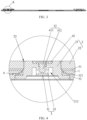
FIG. 3 is a cross-sectional view of a battery cap according to an embodiment of the present disclosure. -
FIG. 4 is a partially enlarged view at site A inFIG. 3 . - In the drawings:
- 1. cap body; 11. mounting hole;
- 2. conductive assembly; 21. electrode pole; 211. electrolyte injection hole; 212. guide groove; 22. terminal; 23. welding groove;
- 3. baffle assembly; 31. baffle; 32. connecting piece;
- 41. seal; 411. first sealing portion; 412, second sealing portion; 42. sealing sheet;
- 51. first insulating member; 52. second insulating member; 521. stop bar;
- 6. seal ring.
- As shown in
FIGS. 1 to 4 , the present embodiment provides a battery cap including acap body 1, a conductive assembly 2, and aseal 41. Thecap body 1 is provided with amounting hole 11. The conductive assembly 2 includes anelectrode pole 21. Theelectrode pole 21 is disposed through themounting hole 11. Theelectrode pole 21 is provided with anelectrolyte injection hole 211. Theelectrolyte injection hole 211 penetrates through both ends of theelectrode pole 21. Theseal 41 is configured to plug theelectrolyte injection hole 211. A length of theseal 41 in a first direction is less than a length of theelectrode pole 21 in the first direction, and the first direction is parallel to an axial direction of theelectrolyte injection hole 211. - The
electrode pole 21 is disposed through themounting hole 11 in thecap body 1 and configured to draw out a voltage in the battery, and is a necessary structure of the battery. When electrolytes are injected, the electrolytes enter a battery core through theelectrolyte injection hole 211 in theelectrode pole 21. After the electrolyte injection is completed, theelectrolyte injection hole 211 is plugged with theseal 41, and the length of theseal 41 in the first direction is less than the length of theelectrode pole 21 in the first direction. By providing theelectrolyte injection hole 211 in theelectrode pole 21, the battery cap not only avoids theseal 41 from occupying a capacity of the battery core, which reduces a volume of the battery, but also prevents theseal 41 from interfering with the electrode assembly, thereby ensuring safety of the battery. - The battery cap further includes a
seal ring 6 which is fitted outside theelectrode pole 21 and configured to seal a spacing between theelectrode pole 21 and the mountinghole 11 to prevent the electrolytes from leaking from the spacing between theelectrode pole 21 and the mountinghole 11. In the present embodiment, theseal ring 6 is made of a rubber material, and has a good sealing effect. - As shown in
FIG. 4 , the battery cap further includes abaffle assembly 3 and a plurality of connectingpieces 32. Thebaffle 31 is spaced apart from theelectrolyte injection hole 211 in the axial direction of theelectrolyte injection hole 211. The connectingpieces 32 are supported between edges of thebaffle 31 and theelectrolyte injection hole 211 at intervals. When the electrolytes are injected, the electrolytes flow out of theelectrolyte injection hole 211 and then impinge on thebaffle 31, followed by the electrolytes flowing out at the intervals between the plurality of connectingpieces 32 and entering the battery core, thereby avoiding impact on the battery core during the electrolyte injection and protecting the diaphragm(s) of the battery core. In the present embodiment, a surface of thebaffle 31 is perpendicular to the axial direction of theelectrolyte injection hole 211, so that the impact of the electrolyte may be effectively resisted. The connectingpiece 32 is in the form of a block and is integrally formed with thebaffle 31. - The
baffle 31 is provided with a flow guide protrusion on one side toward theelectrolyte injection hole 211. When the electrolytes are injected, the electrolytes flow out of theelectrolyte injection hole 211 and then impinge on the flow guide protrusion of thebaffle 31, and then falls from the flow guide protrusion to the surface of thebaffle 31, and flows out at the intervals between the plurality of connectingpieces 32, thereby completing the electrolyte injection. The electrolytes flow toward the surface of thebaffle 31 through the flow guide protrusion. Compared with directly impinging on the surface of thebaffle 31, the kinetic energy of the electrolytes is increased, and the flow rate is accelerated, thereby further improving the electrolyte injection efficiency of the battery. In the present embodiment, the flow guide protrusion is arranged coaxially with theelectrolyte injection hole 211 so that the electrolytes flowing out of theelectrolyte injection hole 211 can smoothly flow through the flow guide protrusion. By way of example, the flow guide protrusion may be a hemisphere, a truncated cone, or a conical structure. - Corners of the
baffle 31 are chamfered so that the flow of electrolytes on thebaffle 31 is more smooth and the flow rate is increased. - As shown in
FIG. 4 , theseal 41 includes afirst sealing portion 411 and asecond sealing portion 412 that are connected. Thesecond sealing portion 412 is located between thefirst sealing portion 411 and thebaffle 31. A bottom end of thesecond sealing portion 412 protrudes from theelectrolyte injection hole 211, and thesecond sealing portion 412 is provided at a distance from the connectingpieces 32. Thefirst sealing portion 411 of theseal 41 can plug theelectrolyte injection hole 211, and thesecond sealing portion 412 is provided at a distance from the connectingpieces 32, so that theseal 41 is easily and smoothly inserted into theelectrolyte injection hole 211. In the present embodiment, a cross-sectional dimension of thefirst sealing portion 411 in a radial direction of theelectrolyte injection hole 211 is greater than a cross-sectional dimension of thesecond sealing portion 412 in the radial direction of theelectrolyte injection hole 211, and corners of the bottom end of thesecond sealing portion 412 are chamfered. By way of example, theseal 41 is a sealing gluey grain. - The bottom end of the
second sealing portion 412 abuts thebaffle 31, so that theseal 41 is firmly positioned and is not easily movable within theelectrolyte injection hole 211 along the axial direction thereof. In the present embodiment, the bottom end of thesecond sealing portion 412 abuts the flow guide protrusion. In other embodiments, if the flow guide protrusion is not coaxial with theelectrolyte injection hole 211, the bottom end of thesecond sealing portion 412 is provided at a distance from the flow guide protrusion. - The battery cap further includes a sealing
sheet 42. Theelectrode pole 21 is provided with a first electrolyte injection hole section and a second electrolyte injection hole section that are connected and penetrate through it. The first electrolyte injection hole section and the second electrolyte injection hole section form theelectrolyte injection hole 211 as described above. The first electrolyte injection hole section is located at a side of the second electrolyte injection hole section facing away from the battery core. The sealingsheet 42 is accommodated in the first electrolyte injection hole section, and the sealingsheet 42 is connected to theelectrode pole 21. Theseal 41 is inserted into the second electrolyte injection hole section. The sealingsheet 42 in the first electrolyte injection hole section and theseal 41 in the second electrolyte injection hole section are arranged to double-seal theelectrolyte injection hole 211, so that the electrolytes in the battery core is prevented from overflowing. And during use of the battery, gas is generated inside the battery core, and the sealingsheet 42 plugged on an outer side of theseal 41 can prevent theseal 41 from being ejected from theelectrolyte injection hole 211 under gas pressure. In the present embodiment, the sealingsheet 42 is made of aluminium and has good electrical conductivity, and can assist theelectrode pole 21 in electrical conduction. - A pore diameter of the first electrolyte injection hole section is greater than that of the second electrolyte injection hole section, so that the electrolytes can flow into the
electrolyte injection hole 211 more accurately when the electrolytes are injected. In the present embodiment, the pore diameter of the first electrolyte injection hole section decreases gradually in a direction toward the second electrolyte injection hole section, which serves as a flow guide. - As shown in
FIG. 4 , the sealingsheet 42 and theelectrode pole 21 are connected by welding, and a gap is provided between the sealingsheet 42 and theseal 41 to accommodate a part of the gas generated during the welding process, so that the sealingsheet 42 is prevented from being ejected from theelectrolyte injection hole 211. - As shown in
FIGS. 2 and4 , one end of theelectrode pole 21 adjacent to the battery core is provided with aguide groove 212, which communicates with theelectrolyte injection hole 211. Thebaffle assembly 3 is located in theguide groove 212, and the connectingpieces 32 are provided at a distance from a groove wall of theguide groove 212. When the electrolytes flow out of the spacing between the plurality of connectingpieces 32, the electrolytes flow along the wall of theguide groove 212, so that the electrolytes entering the battery core quickly collect and the injection time is shortened. - The
guide groove 212 includes a first groove section and a second groove section in communication. The second groove section is located on a side of theguide groove 212 adjacent to the battery core. The first groove section is located on a side of theguide groove 212 away from the battery core. An inner diameter of the second groove section is greater than an inner diameter of the first groove section, so that the weight of the battery can be reduced on the basis of expanding the battery capacity. - The conductive assembly 2 further includes a terminal 22 disposed on a side of the
cap body 1 facing away from the battery core. The terminal 22 is provided with a connection hole. Theelectrode pole 21 is disposed through the connection hole, and a surface of theelectrode pole 21 is flush with a surface of the terminal 22. The terminal 22 having a greater cross-sectional area serves as an electrical contact for connecting a load to the battery, assisting theelectrode pole 21 having a smaller cross-sectional area in outputting electrical energy. - The battery cap further includes a first insulating
member 51 sandwiched between the terminal 22 and thecap body 1 to prevent thecap body 1 having a conductive property from being in contact with the terminal 22 to cause a short circuit of the battery. In the present embodiment, the first insulatingmember 51 is provided with a recess. The terminal 22 is accommodated in the recess, with only a top surface exposed for contacting the load. By way of example, the first insulatingmember 51 is an upper plastic. - A
welding groove 23 is formed at a junction of theelectrode pole 21 and the terminal 22, and theelectrode pole 21 and the terminal 22 are connected by welding. Welding is performed in thewelding groove 23, which may compensate for a height of the protrusion produced by the welding and avoid affecting the surface flatness of the terminal 22 and theelectrode pole 21. - The battery cap further includes a second insulating
member 52 disposed on a side of thecap body 1 adjacent to the battery core. A second avoidance hole is provided in the second insulatingmember 52. Astop bar 521 is provided at an edge of the second avoidance hole. Theelectrode pole 21 includes a pillar portion and a convex portion. The convex portion is circumferentially disposed around the pillar portion. The pillar portion is disposed through the second avoidance hole and the mountinghole 11. The convex portion is disposed through the second avoidance hole and abuts thestop bar 521. The second insulatingmember 52 isolates thecap body 1 with electrically conductive properties from the battery core to avoid battery leakage. Meanwhile, theelectrode pole 21 abuts thestop bar 521 on the second insulatingmember 52, so that theelectrode pole 21 is fixed with respect to the positions of the first insulatingmember 51 and the second insulatingmember 52. In the present embodiment, theguide groove 212 is provided at one end of the pillar portion adjacent to the convex portion. The convex portion is shaped like a flange of the pillar portion. By way of example, the second insulatingmember 52 is a lower plastic. - The present embodiment further provides a battery including a battery case and a battery cap as described above, wherein the battery cap is provided on the battery case. The
electrolyte injection hole 211 is provided on theelectrode pole 21, so that the capacity of the battery core is prevented from being occupied by theseal 41, the volume of the battery is reduced while the capacity of the battery core is ensured, and interference of theseal 41 with the electrode assembly of the battery is avoided, thereby improving the safety of the battery.
Claims (16)
- A battery cap comprising:a cap body (1) provided with a mounting hole (11);a conductive assembly (2) including an electrode pole (21), the electrode pole (21) being disposed through the mounting hole (11), the electrode pole (21) being provided with an electrolyte injection hole (211), the electrolyte injection hole (211) penetrating through both ends of the electrode pole (21);a seal (41) configured to plug the electrolyte injection hole (211) and having a length in a first direction that is less than a length of the electrode pole (21) in the first direction, the first direction being parallel to an axial direction of the electrolyte injection hole (211).
- The battery cap according to claim 1, further comprising a baffle assembly (3) including a baffle (31) and a plurality of connecting pieces (32), the baffle (31) being spaced apart from the electrolyte injection hole (211) in the axial direction of the electrolyte injection hole (211), the connecting pieces (32) being supported between edges of the baffle (31) and the electrolyte injection hole (211).
- The battery cap according to claim 2, wherein the seal (41) includes a first sealing portion (411) and a second sealing portion (412) that are connected, the second sealing portion (412) being located between the first sealing portion (411) and the baffle (31), a bottom end of the second sealing portion (412) protruding from the electrolyte injection hole (211), and the second sealing portion (412) being provided at a distance from the connecting pieces (32).
- The battery cap according to claim 3, wherein a cross-sectional dimension of the first sealing portion (411) in a radial direction of the electrolyte injection hole (211) is greater than a cross-sectional dimension of the second sealing portion (412) in the radial direction of the electrolyte injection hole (211), and corners of the bottom end of the second sealing portion (412) are chamfered.
- The battery cap according to claim 3, wherein the bottom end of the second sealing portion (412) abuts the baffle (31).
- The battery cap according to claim 3, wherein the baffle (31) is provided with a flow guide protrusion on one side toward the electrolyte injection hole (211), and the bottom end of the second sealing portion (412) is provided at a distance from or abuts the flow guide protrusion.
- The battery cap according to claim 6, wherein the flow guide protrusion is arranged coaxially with the electrolyte injection hole (211).
- The battery cap according to any one of claims 1 to 7, further comprising a sealing sheet (42), the electrode pole (21) being provided with a first electrolyte injection hole section and a second electrolyte injection hole section that are connected and penetrate through the electrode pole (21), the first electrolyte injection hole section being located on a side of the second electrolyte injection hole section facing away from a battery core, the sealing sheet (42) being accommodated in the first electrolyte injection hole section, and the sealing sheet (42) being connected to the electrode pole (21), the sealing sheet (41) being inserted into the second electrolyte injection hole section.
- The battery cap according to claim 8, wherein a pore diameter of the first electrolyte injection hole section is greater than a pore diameter of the second electrolyte injection hole section; and/or the pore diameter of the first electrolyte injection hole section decreases gradually in a direction toward the second electrolyte injection hole section.
- The battery cap according to claim 8, wherein the sealing sheet (42) and the electrode pole (21) are connected by welding, and a gap is provided between the sealing sheet (42) and the seal (41).
- The battery cap according to any one of claims 2 to 7, wherein one end of the electrode pole (21) adjacent to the battery core is provided with a guide groove (212), the guide groove (212) communicates with the electrolyte injection hole (211), the baffle assembly (3) is located in the guide groove (212), and the connecting pieces (32) are provided at a distance from a groove wall of the guide groove (212).
- The battery cap according to claim 11, wherein the guide groove (212) includes a first groove section and a second groove section in communication, the second groove section being located on a side of the guide groove (212) adjacent to the battery core, the first groove section being located on a side of the guide groove (212) away from the battery core, an inner diameter of the second groove section being greater than an inner diameter of the first groove section.
- The battery cap according to any one of claims 1 to 7, wherein the conductive assembly (2) further includes a terminal (22) disposed on a side of the cap body (1) facing away from a battery core, the terminal (22) being provided with a connection hole, the electrode pole (21) being disposed through the connection hole, and a surface of the electrode pole (21) being flush with a surface of the terminal (22), the battery cap further comprising a first insulating member (51) sandwiched between the terminal (22) and the cap body (1).
- The battery cap according to claim 13, wherein a welding groove (23) is formed at a junction of the electrode pole (21) and the terminal (22), and the electrode pole (21) and the terminal (22) are connected by welding.
- The battery cap according to any one of claims 1-14, further comprising a seal ring (6) fitted outside the electrode pole (21) and configured to seal a spacing between the electrode pole (21) and the mounting hole (11).
- A battery comprising a battery case and the battery cap according to any one of claims 1 to 15, the battery cap being provided on the battery case.
Applications Claiming Priority (3)
| Application Number | Priority Date | Filing Date | Title |
|---|---|---|---|
| CN202310625423.1A CN116435725A (en) | 2023-05-30 | 2023-05-30 | Battery top cover and battery |
| CN202321345871.8U CN220710446U (en) | 2023-05-30 | 2023-05-30 | Battery top cap and battery |
| PCT/CN2024/096361 WO2024245345A1 (en) | 2023-05-30 | 2024-05-30 | Battery top cover and battery |
Publications (2)
| Publication Number | Publication Date |
|---|---|
| EP4496115A1 true EP4496115A1 (en) | 2025-01-22 |
| EP4496115A4 EP4496115A4 (en) | 2025-12-24 |
Family
ID=93258899
Family Applications (1)
| Application Number | Title | Priority Date | Filing Date |
|---|---|---|---|
| EP24787040.5A Pending EP4496115A4 (en) | 2023-05-30 | 2024-05-30 | BATTERY COVER AND BATTERY |
Country Status (2)
| Country | Link |
|---|---|
| EP (1) | EP4496115A4 (en) |
| WO (1) | WO2024245345A1 (en) |
Families Citing this family (1)
| Publication number | Priority date | Publication date | Assignee | Title |
|---|---|---|---|---|
| CN120199960B (en) * | 2025-05-27 | 2025-10-10 | 深圳海辰储能科技有限公司 | End cover assembly, energy storage device and electric equipment |
Family Cites Families (12)
| Publication number | Priority date | Publication date | Assignee | Title |
|---|---|---|---|---|
| JP2007018915A (en) * | 2005-07-08 | 2007-01-25 | Nec Tokin Corp | Sealed battery |
| JP6090571B2 (en) * | 2013-04-11 | 2017-03-08 | 株式会社豊田自動織機 | Power storage device |
| CN110707281B (en) * | 2019-10-10 | 2021-12-14 | 江西赣锋电池科技有限公司 | Secondary cell top cap fluid infusion structure |
| CN215377527U (en) * | 2021-05-26 | 2021-12-31 | 江西赣锋锂电科技有限公司 | Secondary battery top cover sealed by microstructure |
| CN216671861U (en) * | 2021-12-30 | 2022-06-03 | 江苏天合储能有限公司 | Utmost point post subassembly, battery top cap and battery |
| CN216698529U (en) * | 2021-12-31 | 2022-06-07 | 江西百思利新能源科技股份有限公司 | Secondary battery top cap and secondary battery thereof |
| CN114725593B (en) * | 2022-04-06 | 2025-11-07 | 力神(青岛)新能源有限公司 | Battery cover with annotate liquid water conservancy diversion structure |
| CN217468686U (en) * | 2022-05-12 | 2022-09-20 | 武汉楚能新能源有限公司 | Power battery top cap and power battery |
| CN217306722U (en) * | 2022-07-01 | 2022-08-26 | 宁德时代新能源科技股份有限公司 | End cap assemblies, battery cells, batteries and electrical devices |
| CN218300000U (en) * | 2022-09-08 | 2023-01-13 | 广东省豪鹏新能源科技有限公司 | Cover plate assembly and button cell |
| CN220710446U (en) * | 2023-05-30 | 2024-04-02 | 湖北亿纬动力有限公司 | Battery top cap and battery |
| CN116435725A (en) * | 2023-05-30 | 2023-07-14 | 湖北亿纬动力有限公司 | Battery top cover and battery |
-
2024
- 2024-05-30 EP EP24787040.5A patent/EP4496115A4/en active Pending
- 2024-05-30 WO PCT/CN2024/096361 patent/WO2024245345A1/en not_active Ceased
Also Published As
| Publication number | Publication date |
|---|---|
| EP4496115A4 (en) | 2025-12-24 |
| WO2024245345A1 (en) | 2024-12-05 |
Similar Documents
| Publication | Publication Date | Title |
|---|---|---|
| CN110880563B (en) | Battery case assembly and battery having the same | |
| US12334570B2 (en) | Top cover assembly of secondary battery and secondary battery | |
| CN217158535U (en) | A cover plate assembly for a battery, a cylindrical battery and a battery pack | |
| CN109713353B (en) | Secondary battery, secondary battery assembling method, and battery module | |
| JP5227297B2 (en) | Secondary battery | |
| EP3764418B1 (en) | Cap assembly and secondary battery | |
| KR101093957B1 (en) | Secondary battery | |
| KR102680621B1 (en) | Cylindrical secondary battery | |
| CN210006772U (en) | Top cap assembly and secondary battery | |
| CN116435725A (en) | Battery top cover and battery | |
| EP4496115A1 (en) | Battery top cover and battery | |
| KR20240152908A (en) | Batteries, battery packs and vehicles | |
| KR20240155911A (en) | Batteries, battery packs and vehicles | |
| US20240304912A1 (en) | Battery | |
| CN217788567U (en) | Cover plate assembly of battery and battery | |
| CN223625178U (en) | Cover plate assembly, battery cell and battery pack | |
| WO2023103395A1 (en) | Battery top cover plate and battery | |
| CN220710446U (en) | Battery top cap and battery | |
| KR100696777B1 (en) | Lithium ion secondary battery | |
| CN220934361U (en) | Cylindrical batteries, battery devices | |
| CN208256767U (en) | Secondary cell | |
| CN119153910A (en) | Secondary battery | |
| CN217426920U (en) | Button cell | |
| KR20240155895A (en) | Batteries, battery packs and vehicles | |
| KR20070005338A (en) | Cap assembly and a lithium ion secondary battery having the same |
Legal Events
| Date | Code | Title | Description |
|---|---|---|---|
| STAA | Information on the status of an ep patent application or granted ep patent |
Free format text: STATUS: UNKNOWN |
|
| STAA | Information on the status of an ep patent application or granted ep patent |
Free format text: STATUS: THE INTERNATIONAL PUBLICATION HAS BEEN MADE |
|
| PUAI | Public reference made under article 153(3) epc to a published international application that has entered the european phase |
Free format text: ORIGINAL CODE: 0009012 |
|
| STAA | Information on the status of an ep patent application or granted ep patent |
Free format text: STATUS: REQUEST FOR EXAMINATION WAS MADE |
|
| 17P | Request for examination filed |
Effective date: 20241017 |
|
| AK | Designated contracting states |
Kind code of ref document: A1 Designated state(s): AL AT BE BG CH CY CZ DE DK EE ES FI FR GB GR HR HU IE IS IT LI LT LU LV MC ME MK MT NL NO PL PT RO RS SE SI SK SM TR |
|
| A4 | Supplementary search report drawn up and despatched |
Effective date: 20251125 |
|
| RIC1 | Information provided on ipc code assigned before grant |
Ipc: H01M 50/645 20210101AFI20251119BHEP Ipc: H01M 50/627 20210101ALI20251119BHEP Ipc: H01M 50/553 20210101ALI20251119BHEP Ipc: H01M 50/15 20210101ALI20251119BHEP Ipc: H01M 50/148 20210101ALI20251119BHEP Ipc: H01M 50/174 20210101ALI20251119BHEP Ipc: H01M 50/188 20210101ALI20251119BHEP Ipc: H01M 50/55 20210101ALI20251119BHEP Ipc: H01M 50/566 20210101ALI20251119BHEP |