EP4496101A1 - Secondary battery assembly - Google Patents
Secondary battery assembly Download PDFInfo
- Publication number
- EP4496101A1 EP4496101A1 EP24188987.2A EP24188987A EP4496101A1 EP 4496101 A1 EP4496101 A1 EP 4496101A1 EP 24188987 A EP24188987 A EP 24188987A EP 4496101 A1 EP4496101 A1 EP 4496101A1
- Authority
- EP
- European Patent Office
- Prior art keywords
- hole
- secondary battery
- battery assembly
- case
- accommodating
- Prior art date
- Legal status (The legal status is an assumption and is not a legal conclusion. Google has not performed a legal analysis and makes no representation as to the accuracy of the status listed.)
- Pending
Links
Images


Classifications
-
- H—ELECTRICITY
- H01—ELECTRIC ELEMENTS
- H01M—PROCESSES OR MEANS, e.g. BATTERIES, FOR THE DIRECT CONVERSION OF CHEMICAL ENERGY INTO ELECTRICAL ENERGY
- H01M50/00—Constructional details or processes of manufacture of the non-active parts of electrochemical cells other than fuel cells, e.g. hybrid cells
- H01M50/30—Arrangements for facilitating escape of gases
- H01M50/383—Flame arresting or ignition-preventing means
-
- H—ELECTRICITY
- H01—ELECTRIC ELEMENTS
- H01M—PROCESSES OR MEANS, e.g. BATTERIES, FOR THE DIRECT CONVERSION OF CHEMICAL ENERGY INTO ELECTRICAL ENERGY
- H01M10/00—Secondary cells; Manufacture thereof
- H01M10/60—Heating or cooling; Temperature control
- H01M10/65—Means for temperature control structurally associated with the cells
- H01M10/655—Solid structures for heat exchange or heat conduction
- H01M10/6556—Solid parts with flow channel passages or pipes for heat exchange
- H01M10/6557—Solid parts with flow channel passages or pipes for heat exchange arranged between the cells
-
- H—ELECTRICITY
- H01—ELECTRIC ELEMENTS
- H01M—PROCESSES OR MEANS, e.g. BATTERIES, FOR THE DIRECT CONVERSION OF CHEMICAL ENERGY INTO ELECTRICAL ENERGY
- H01M50/00—Constructional details or processes of manufacture of the non-active parts of electrochemical cells other than fuel cells, e.g. hybrid cells
- H01M50/20—Mountings; Secondary casings or frames; Racks, modules or packs; Suspension devices; Shock absorbers; Transport or carrying devices; Holders
- H01M50/204—Racks, modules or packs for multiple batteries or multiple cells
-
- H—ELECTRICITY
- H01—ELECTRIC ELEMENTS
- H01M—PROCESSES OR MEANS, e.g. BATTERIES, FOR THE DIRECT CONVERSION OF CHEMICAL ENERGY INTO ELECTRICAL ENERGY
- H01M10/00—Secondary cells; Manufacture thereof
- H01M10/60—Heating or cooling; Temperature control
- H01M10/64—Heating or cooling; Temperature control characterised by the shape of the cells
- H01M10/647—Prismatic or flat cells, e.g. pouch cells
-
- H—ELECTRICITY
- H01—ELECTRIC ELEMENTS
- H01M—PROCESSES OR MEANS, e.g. BATTERIES, FOR THE DIRECT CONVERSION OF CHEMICAL ENERGY INTO ELECTRICAL ENERGY
- H01M10/00—Secondary cells; Manufacture thereof
- H01M10/60—Heating or cooling; Temperature control
- H01M10/65—Means for temperature control structurally associated with the cells
- H01M10/656—Means for temperature control structurally associated with the cells characterised by the type of heat-exchange fluid
- H01M10/6561—Gases
- H01M10/6563—Gases with forced flow, e.g. by blowers
-
- H—ELECTRICITY
- H01—ELECTRIC ELEMENTS
- H01M—PROCESSES OR MEANS, e.g. BATTERIES, FOR THE DIRECT CONVERSION OF CHEMICAL ENERGY INTO ELECTRICAL ENERGY
- H01M50/00—Constructional details or processes of manufacture of the non-active parts of electrochemical cells other than fuel cells, e.g. hybrid cells
- H01M50/20—Mountings; Secondary casings or frames; Racks, modules or packs; Suspension devices; Shock absorbers; Transport or carrying devices; Holders
- H01M50/204—Racks, modules or packs for multiple batteries or multiple cells
- H01M50/207—Racks, modules or packs for multiple batteries or multiple cells characterised by their shape
- H01M50/209—Racks, modules or packs for multiple batteries or multiple cells characterised by their shape adapted for prismatic or rectangular cells
-
- H—ELECTRICITY
- H01—ELECTRIC ELEMENTS
- H01M—PROCESSES OR MEANS, e.g. BATTERIES, FOR THE DIRECT CONVERSION OF CHEMICAL ENERGY INTO ELECTRICAL ENERGY
- H01M50/00—Constructional details or processes of manufacture of the non-active parts of electrochemical cells other than fuel cells, e.g. hybrid cells
- H01M50/20—Mountings; Secondary casings or frames; Racks, modules or packs; Suspension devices; Shock absorbers; Transport or carrying devices; Holders
- H01M50/233—Mountings; Secondary casings or frames; Racks, modules or packs; Suspension devices; Shock absorbers; Transport or carrying devices; Holders characterised by physical properties of casings or racks, e.g. dimensions
- H01M50/24—Mountings; Secondary casings or frames; Racks, modules or packs; Suspension devices; Shock absorbers; Transport or carrying devices; Holders characterised by physical properties of casings or racks, e.g. dimensions adapted for protecting batteries from their environment, e.g. from corrosion
-
- Y—GENERAL TAGGING OF NEW TECHNOLOGICAL DEVELOPMENTS; GENERAL TAGGING OF CROSS-SECTIONAL TECHNOLOGIES SPANNING OVER SEVERAL SECTIONS OF THE IPC; TECHNICAL SUBJECTS COVERED BY FORMER USPC CROSS-REFERENCE ART COLLECTIONS [XRACs] AND DIGESTS
- Y02—TECHNOLOGIES OR APPLICATIONS FOR MITIGATION OR ADAPTATION AGAINST CLIMATE CHANGE
- Y02E—REDUCTION OF GREENHOUSE GAS [GHG] EMISSIONS, RELATED TO ENERGY GENERATION, TRANSMISSION OR DISTRIBUTION
- Y02E60/00—Enabling technologies; Technologies with a potential or indirect contribution to GHG emissions mitigation
- Y02E60/10—Energy storage using batteries
Definitions
- Embodiments of the present disclosure relate to a secondary battery assembly. Specifically, they relate to a structure of a secondary battery assembly capable of delaying thermal propagation (TP).
- TP thermal propagation
- the operating principle of lithium secondary batteries is an electrochemical oxidation-reduction reaction. More specifically, the operating principle of lithium secondary batteries is that electricity is generated through the movement of lithium ions between the anode and the cathode during charging and discharging cycles. During the charging, a voltage is applied that causes the lithium ions to move from the cathode to the anode. During the discharging cycle the lithium ions move back from the anode to the cathode while electrons flow from the anode to the cathode through the external circuit thus providing a current to a load connected to the external circuit. In the case of a lithium secondary battery, during the discharging cycle lithium ions in the anode escape therefrom (a process known as de-intercalation) and move to the cathode through the electrolyte and the separator
- lithium secondary batteries Recently, due to fire or explosion accidents occurring during the use of lithium secondary batteries, social concerns about the safety of battery use are increasing. Based on these social concerns, one recent major developmental task for lithium secondary batteries is to eliminate instabilities such as fire and explosion caused by thermal runaway of secondary battery cells.
- air is advantageously discharged air from the inside of a secondary battery assembly or the inside of a secondary battery assembly easily filled with a non-combustible gas.
- a problem that the embodiments advantageously solve is minimizing or preventing fire and explosion of a secondary battery assembly.
- the lifespan and stability of a secondary battery assembly is substantially improved.
- the secondary battery assembly of the present disclosure can be widely applied in the field of electric vehicles, battery charging stations, energy storage system (ESS), and green technology, such as photovoltaics, and wind power generation using batteries.
- the secondary battery assembly of the present disclosure can be used in eco-friendly electric vehicles mobility to prevent climate change by suppressing air pollution and greenhouse gas emissions, including electric vehicles and hybrid vehicles.
- a secondary battery assembly may include a plurality of battery cells; a case forming an accommodating space for accommodating the plurality of battery cells; and a non-combustible gas filled into the accommodating space.
- the secondary battery assembly may further include a first hole and a second hole penetrating the case and communicating with the accommodating space; and a first closing member and a second closing member coupled to the case to close the first hole and the second hole.
- the first closing member and the second closing member may each include a hole sealing portion for sealing the first hole and the second hole.
- the first hole and the second hole may be formed on one surface of the case.
- the distance from the first hole to the second hole may be longer than the length from one edge of the one surface of the case.
- the first hole and the second hole may be positioned diagonally on the one surface of the case.
- the size of the inner diameter of the first hole may be different from the size of the inner diameter of the second hole.
- the case may include an accommodating body including an opening portion at the top; and an accommodating cover coupled to the accommodating body to close the opening portion, and the first hole and the second hole may be positioned on the accommodating cover.
- the case may further include a body sealing portion positioned between the accommodating body and the accommodating cover.
- the first hole and the second hole may each be provided in a plural number.
- the plurality of first holes may be positioned in a first area adjacent to one edge in the one surface of the case, and the plurality of second holes may be positioned in a second area different from the first area in the one surface of the case.
- the non-combustible gas may be one selected from the group including nitrogen, argon, helium, and carbon dioxide or a combination thereof.
- the secondary battery assembly may further include a first hole formed on one side surface of the case; and a second hole formed on the other side surface of the case opposing the first hole.
- the height of the first hole and the height of the second hole may be different based on the bottom surface of the case.
- the secondary battery assembly may include a plurality of battery cells; and a case forming an accommodating space for accommodating the plurality of battery cells; and the pressure of the accommodating space may be maintained at a preset vacuum pressure lower than an air pressure outside the case.
- the secondary battery assembly may include a plurality of battery cells; and a case forming an accommodating space for accommodating the plurality of battery cells; and an oxygen concentration in the accommodating space may be maintained below a preset allowable combustion concentration.
- the air inside of a secondary battery assembly can be discharged or the inside of a secondary battery assembly can be easily filled with a non-combustible gas.
- fire and explosion of a secondary battery assembly can be minimized or prevented.
- the lifespan and stability of a secondary battery assembly can be improved.
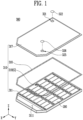
- FIG. 1 shows an exploded simplified schematic diagram of a secondary battery assembly 300 according to an embodiment of the present disclosure.
- a secondary battery assembly 300 is a general term for a battery module or battery pack.
- the battery module refers to a secondary battery assembly in which a plurality of battery cells are grouped together in a number of one or greater and placed in a case to protect them from external shock, heat, vibration, or the like.
- the battery pack refers to a secondary battery assembly accommodating a preset number of battery modules to achieve a finally desired voltage or power.
- a secondary battery assembly 300 may refer to a battery of a cell-to-pack (CTP) structure that generates a desired voltage or power by accommodating a preset number of battery cells while omitting the battery module.
- CTP cell-to-pack
- a secondary battery assembly 300 may include a plurality of battery cells 110 (see FIG. 2 ) producing or storing electric energy and a case forming an accommodating space 319 for accommodating the plurality of battery cells 110.
- the secondary battery assembly 300 may include a battery module 200 including a plurality of battery cells 110 and a case 310 forming an accommodating space 319 accommodating the battery module 200.
- a secondary battery assembly 300 may include a non-combustible gas G filled into the accommodating space 319 to prevent fire and explosion of a battery cell 110 or a battery module 200. Because the non-combustible gas G is generally colorless and transparent and a space filled with the non-combustible gas G is the accommodating space 319, so in FIG. 1 , the accommodating space 319 and the non-combustible gas are indicated as pointing to a same position.
- the non-combustible gas G may be a colored or opaque gas.
- the non-combustible gas G is colored or opaque, leakage from the case 310 may be visually confirmed.
- non-combustible gas G refers to a gas that cannot combust itself nor has the property of combusting when it is together with other substances. So non-combustible gas refers to a gas that is unrelated to combustion.
- the non-combustible gas G may be an inert gas (or noble gas) such as water vapor (H 2 O), nitrogen (N 2 ), carbon dioxide (CO 2 ), helium (He), and argon (AR).
- inert gas or noble gas
- nitrogen N 2
- carbon dioxide CO 2
- He helium
- argon AR
- CFCs chlorofluorocarbons
- the non-combustible gas G may preferably be one selected from the group including nitrogen, argon, helium, and carbon dioxide or a combination of thereof.
- non-combustible gas G may include other colored gases as described above.
- the non-combustible gas G When the non-combustible gas G is filled into the accommodating space 319, the non-combustible gas may minimize the contact with oxygen by the plurality of battery cells 110 or the battery module 200, and thus it may perform a function of minimizing or suppressing fire and explosion of the plurality of battery cells 110 or the battery module 200.
- the non-combustible gas G may be filled into the accommodating space 319 at a preset filling pressure.
- a secondary battery assembly 300 may maintain the pressure of the accommodating space 319 at a preset vacuum pressure lower than an air pressure outside the case 310.
- the accommodating space 319 may be filled with a non-combustible gas G at the filling pressure, or, alternatively, the inside of the accommodating space 319 may be maintained at the vacuum pressure.
- filling the accommodating space 319 with a non-combustible gas G or maintaining the accommodating space 319 in a state close to a vacuum is designed to lower the oxygen concentration in the accommodating space 319. This is because, when the oxygen concentration in the accommodating space 319 is maintained lower than a combustible oxygen concentration in the battery cells 110 or the battery module 200, fire and explosion of the battery cells 110 or the battery module 200 may be minimized.
- the secondary battery assembly 300 may maintain the oxygen concentration in the accommodating space 319 below a preset allowable combustion concentration.
- the allowable combustion concentration may vary depending on the volume of the case 310, the number of battery cells 110, and the degree of progression of a thermal runaway.
- the case 310 may include an accommodating body 311 including an opening 3111 at the top, and an accommodating cover 317 coupled to the accommodating body 311 adapted to close the opening portion 3111.
- the accommodating body 311 may accommodate the plurality of battery cells 110 or the battery module 200 through the opening portion 3111.
- the accommodating cover 317 may be coupled to the accommodating body 311 to close the opening portion 3111.
- the empty space of the accommodating space 319 refers to a space that is generally filled with air after the plurality of battery cells 110 are accommodated in the accommodating space 319.
- the secondary battery assembly 300 may discharge the air accommodated in the accommodating space 319 and maintain the pressure of the accommodating space 319 below the vacuum pressure.
- the secondary battery assembly 300 may include a first hole 321 and a second hole 325 penetrating the case 310 and communicating with the accommodating space 319.
- the secondary battery assembly 300 may include a first closing member 322 and a second closing member 326 that close the first hole 321 and the second hole 325.
- the secondary battery assembly 300 may fill the accommodating space 319 with a non-combustible gas G or discharge the air in the accommodating space 319 through the first hole 321 and the second hole 325 to maintain the vacuum pressure.
- the secondary battery assembly 300 may close the first hole 321 and the second hole 325 using the first closing member 322 and the second closing member 326 to block the inside of the accommodating space 319 from the outside.
- the secondary battery assembly 300 may include a body sealing portion 318 positioned between the accommodating body 311 and the accommodating cover 317.
- the body sealing portion 318, the first closing member 322, and the second closing member 326 may minimize or prevent leakage of a gas accommodated in the accommodating space 319 to the outside or inflow of the air outside of the case to the inside of the accommodating space 319.
- the first hole 321 and the second hole 325 may be formed on one surface of the case 310.
- the first hole 321 and the second hole 325 may be positioned on the same one surface of the case 310.
- the one surface of the case 310 may refer to any surface of a bottom surface 313 (see FIG. 5 ) of the case supporting the plurality of battery cells 110, a side surface (not shown) of the case extending from any edge of the bottom surface 313 of the case towards the opening portion 3111 to form the accommodating space 319 together with the bottom surface 313 of the case, and a top surface of the accommodating space 319, or the accommodating cover 317.
- the first hole 321 and the second hole 325 may be formed to penetrate the top surface of the accommodating space 319 (not shown) or the accommodating cover 317. Therefore, the first closing member 322 and the second closing member 326 may be coupled to the top surface of the accommodating space 319 or the accommodating cover 317 to close the first hole 321 and the second hole 325.
- first closing member 322 and the second closing member 326 may be coupled to the top surface of the accommodating space 319 or the accommodating cover 317 by welding.
- the accommodating cover 317 and the accommodating body 311 may also be coupled by welding.
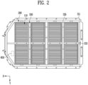
- FIG. 2 shows an accommodating body 311 according to an embodiment of the present disclosure.
- FIG. 2 illustrates an example in which the shape of the accommodating body 311 is asymmetrical along the X-direction. This is considering that the secondary battery assembly 300 is generally positioned at the bottom of an electric vehicle. However, in contrast, the accommodating body 311 and the accommodating cover 317 may have a symmetrical shape, for example, a rectangular shape.
- the accommodating body 311 may accommodate the battery module 200 or the plurality of battery cells 110 therein.
- the accommodating body 311 may include a separating frame 330 for separating the battery module 200 or the plurality of battery cells 110 into sections.
- the separating frame 330 may separate the accommodating space 319 into a plurality of spaces.
- the battery module 200 or the plurality of battery cells 110 may be positioned separately in the plurality of spaces.
- the separating frame 330 may serve to reinforce the strength of the accommodating body 311.
- the separating frame 330 may include a first frame 333 extending in the X-direction and a second frame 335 extending in the Y-direction positioned between the battery module 200 or the plurality of battery cells 110.
- the secondary battery assembly 300 may further include a sensing portion 650 for measuring the pressure of a non-combustible gas G filled in the accommodating space 319.
- the sensing portion 650 may be configured to sense that the pressure of the accommodating space 319 falls below a preset sensing pressure. So, when the non-combustible gas G leaks from the secondary battery assembly 300, the sensing portion 650 may sense that the pressure of the accommodating space 319 falls below a preset sensing pressure.
- the sensing portion 650 may sense that the pressure of the accommodating space 319 increases over the vacuum pressure.
- FIGS. 3A and 3B show a first hole 321 and a second hole 325 according to an embodiment of the present disclosure.
- the secondary battery assembly 300 may fill the accommodating space 319 with a non-combustible gas G or discharge the air in the accommodating space 319 through the first hole 321 and the second hole 325 to maintain the vacuum pressure.
- the non-combustible gas G may be injected into the accommodating space 319 through the first hole 321, and a gas remaining in the accommodating space 319 may be discharged through the second hole 325.
- the air inside the accommodating space 319 may be discharged through the second hole 325, and after a certain period of time, the non-combustible gas may also be discharged through the second hole 325.
- the secondary battery assembly 300 may check whether the non-combustible gas G is filled into the accommodating space 319 up to a preset target amount through the second hole 325.
- the secondary battery assembly 300 may discontinue injection of the non-combustible gas G and close the first and second holes 321 and 325 with the first and second closing members 322 and 326, respectively.
- the inner diameter of the first hole 321 and the inner diameter of the second hole 325 may be different.
- the size of the first hole 321 may be larger than the size of the second hole 325.
- first hole 321 and the second hole 325 have different functions, the first hole 321 and the second hole 325 may be preferably positioned spaced apart from each other in a certain distance or longer.
- the first hole 321 and the second hole 325 may be positioned diagonally on the accommodating cover 317.
- FIG. 3A illustrates the positions of the first hole 321 and the second hole 325 using the top surface of the accommodating space 319 or the accommodating cover 317, but the first hole 321 and the second hole 325 may be positioned anywhere on one side of the case 310.
- the diagonal arrangement of the first hole 321 and the second hole 325 allows the flowing-in non-combustible gas G to remain as much as possible when the non-combustible gas G pushes out the air in the accommodating space 319.
- any pair of edges 3175 and 3177 among two pairs of opposing edges among the four edges of the accommodating cover 317 will be longer than the other pair of edges 3171 and 3173.
- the other pair of edges 3171 and 3173 may be referred to as a pair of the relatively short edges, and the pair of edges 3175 and 3177 may be referred as the pair of relatively long edges.
- the first hole 321 may be positioned closer to the edge 3171 than to the edge 3173.
- the second hole 325 may be positioned closer to the edge 3173 than to the edge 3171.
- first hole 321 may be positioned closer to the 3175 of the pair of long edges 3175 and 3177 than to the edge 3177.
- second hole 325 may be positioned closer to the edge 3177 than to the edge 3175.
- the first hole 321 and the second hole 325 may be positioned diagonally on the accommodating cover 317.
- the distance D1 from the center of the first hole 321 to the center of the second hole 325 may be longer than the length (L1 or L2) of an edge of the accommodating cover 317 on the top surface of the accommodating space 319 or on the accommodating cover 317 or of an edge of the top surface of the accommodating space 319.
- an external device also referred to herein as a discharge device, (not shown) may be used for discharging a gas through a second hole 325 and/or for confirming filling of the non-combustible gas G.
- Another external device also referred to as an injector device, (not shown) may be used for injecting a non-combustible gas G through the first hole 321.
- the ejector and discharge devices may be connected to the first and second holes 321 and 325, respectively. Positioning the first and second holes 321 and 325 diagonally as farther apart from each other as possible may help to prevent one device from interfering with the other, and to clearly distinguish them.
- case 310 should be able to withstand a pressure of 6 bar or higher, which may be generated during a thermal runaway of the plurality of battery cells 110 accommodated therein.
- the secondary battery assembly 300 may include hole sealing portions 323 and 327 positioned between the first hole 321 and the first closing member 322 and between the second hole 325 and the second closing member to seal the first hole 321 and the second hole 325, respectively.
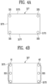
- FIGS. 4A and 4B show variations of a first hole 321 and a second hole 325 according to embodiments of the present disclosure. As illustrated in FIGS. 4A and 4B , the first hole 321 and the second hole 325 may each be provided in a plural number.
- the secondary battery assembly 300 may include a plurality of first holes 321 and a plurality of second holes 325 on the top surface of the accommodating space 319 or on the accommodating cover 317.
- the number of first holes 321 and the number of second holes 325 may be the same. However, in contrast, when the non-combustible gas G may be injected through the plurality of first holes 321 and a gas remaining in the accommodating space 319 may be discharged and filling of the non-combustible gas G may be confirmed through the second hole 325, the number of the first holes 321 and the number of the second holes 325 may be different.
- the two first holes 321 and the two second holes 325 may be positioned adjacently to a corner where the pair of short edges 3171 and 3173 and the pair of long edges 3175 and 3177 meet.
- the spacing between the plurality of first holes 321 may be smaller than the spacing between a first hole 321 among the plurality of first holes 321 and a second hole 325 among the plurality of second holes 325.
- a spacing refers to the length from the center of one hole to the center of another hole.
- the spacing between the plurality of second holes 325 may be smaller than the spacing between a first hole 321 among the plurality of first holes 321 and a second hole 325 among the plurality of second holes 325.
- the plurality of first holes 321 may be positioned in a first area A1 adjacent to a first edge of the one surface of the case 310, and the plurality of second holes 325 may be positioned in a second area A2, which is different from the first area, and may be adjacent to an opposite edge the first edge of the case 310.
- the plurality of first holes 321 may be positioned in a first area A1 adjacent to one edge of the top surface of the accommodating space 319 or of the accommodating cover 317, and the plurality of second holes 325 may be positioned in second area A2, which is different from the first area, of the top surface of the accommodating space 319 or of the accommodating cover 317.
- the first area A1 may be positioned closer to edge 3171 of the pair of short edges 3171 and 3173, and the second area A2 may be positioned relatively closer to the other edge 3173.
- FIG. 5 shows another secondary battery assembly 300 according to an embodiment of the present disclosure.
- the first hole 321 and the second hole 325 may be formed to penetrate a side surface of the accommodating space 319, that is, a side surface of the case 310.
- the case 310 may include a bottom surface 313 of the case supporting the plurality of battery cells 110 and two opposing side surfaces 314 and 315 among side surfaces of the accommodating space 319 extending from any pair of opposing edges among four edges of the bottom surface 313 of the case.
- the first hole 321 may be formed on the side surface 314 of the case among the two opposing side surfaces 314 and 315, and the second hole 325 may be formed on the opposing side surface 315 of the case. It is noted that the two opposing side surfaces 314 and 315 are only examples, and the first hole 321 and the second hole 325 may be formed on two side surfaces opposing in another direction.
- first hole 321 and the second hole 325 may be provided in a plural number.
- the positions of the first hole 321 and the second hole 325 may be different based on the bottom surface 313 of the case. Since the molecular weight of the air in the accommodating space 319 is different from the molecular weight of the non-combustible gas G, in order to effectively discharge the air in the accommodating space 319 and fill the non-combustible gas G, the height H1 of the hole 321 and the height H2 of the second hole 325 may be different.
- FIG. 6 shows still another secondary battery assembly 400 according to an embodiment of the present disclosure.
- the secondary battery assembly 400 may be applied not only to a battery pack but also to a battery module 200.
- the secondary battery assembly 400 may include a case 210 accommodating a plurality of battery cells (not shown), a first hole 221 and a second hole 225 formed to penetrate the case 210, and a first closing member 222 and a second closing member 226 coupled to the case 210 to close the first hole 221 and the second hole 225.
- the secondary battery assembly 400 may be injected with a non-combustible gas (not shown) and confirm filling of the non-combustible gas through the first hole 221 and the second hole 225.
- Embodiments of the present disclosure may be modified and implemented in various forms, and its scope is not limited to the embodiments described above. Therefore, if a modified embodiment includes components of the present disclosure, it should be regarded as falling within the scope of the rights of the present disclosure. Furthermore, the embodiments may be combined to form additional embodiments.
Landscapes
- Chemical & Material Sciences (AREA)
- Chemical Kinetics & Catalysis (AREA)
- Electrochemistry (AREA)
- General Chemical & Material Sciences (AREA)
- Engineering & Computer Science (AREA)
- Manufacturing & Machinery (AREA)
- Battery Mounting, Suspending (AREA)
- Gas Exhaust Devices For Batteries (AREA)
Abstract
Embodiments of the present disclosure relate to a secondary battery assembly including a plurality of battery cells, a case forming an accommodating space for accommodating the plurality of battery cells, and a non-combustible gas accommodated in the accommodating space together with the plurality of battery cells to mitigate or delay the thermal propagation.
Description
- Embodiments of the present disclosure relate to a secondary battery assembly. Specifically, they relate to a structure of a secondary battery assembly capable of delaying thermal propagation (TP).
- The operating principle of lithium secondary batteries is an electrochemical oxidation-reduction reaction. More specifically, the operating principle of lithium secondary batteries is that electricity is generated through the movement of lithium ions between the anode and the cathode during charging and discharging cycles. During the charging, a voltage is applied that causes the lithium ions to move from the cathode to the anode. During the discharging cycle the lithium ions move back from the anode to the cathode while electrons flow from the anode to the cathode through the external circuit thus providing a current to a load connected to the external circuit. In the case of a lithium secondary battery, during the discharging cycle lithium ions in the anode escape therefrom (a process known as de-intercalation) and move to the cathode through the electrolyte and the separator
- Recently, due to fire or explosion accidents occurring during the use of lithium secondary batteries, social concerns about the safety of battery use are increasing. Based on these social concerns, one recent major developmental task for lithium secondary batteries is to eliminate instabilities such as fire and explosion caused by thermal runaway of secondary battery cells.
- According to embodiments of the present disclosure, air is advantageously discharged air from the inside of a secondary battery assembly or the inside of a secondary battery assembly easily filled with a non-combustible gas.
- According to embodiments of the present disclosure, a problem that the embodiments advantageously solve is minimizing or preventing fire and explosion of a secondary battery assembly.
- According to still another embodiment of the present disclosure, the lifespan and stability of a secondary battery assembly is substantially improved.
- Moreover, the secondary battery assembly of the present disclosure can be widely applied in the field of electric vehicles, battery charging stations, energy storage system (ESS), and green technology, such as photovoltaics, and wind power generation using batteries. In addition, the secondary battery assembly of the present disclosure can be used in eco-friendly electric vehicles mobility to prevent climate change by suppressing air pollution and greenhouse gas emissions, including electric vehicles and hybrid vehicles.
- A secondary battery assembly according to an embodiment of the present disclosure may include a plurality of battery cells; a case forming an accommodating space for accommodating the plurality of battery cells; and a non-combustible gas filled into the accommodating space.
- In addition, the secondary battery assembly may further include a first hole and a second hole penetrating the case and communicating with the accommodating space; and a first closing member and a second closing member coupled to the case to close the first hole and the second hole.
- In addition, when a non-combustible gas is injected into the accommodating space through the first hole, at least a part of the gas in the accommodating space may be discharged through the second hole.
- The first closing member and the second closing member may each include a hole sealing portion for sealing the first hole and the second hole.
- The first hole and the second hole may be formed on one surface of the case.
- The distance from the first hole to the second hole may be longer than the length from one edge of the one surface of the case.
- The first hole and the second hole may be positioned diagonally on the one surface of the case.
- The size of the inner diameter of the first hole may be different from the size of the inner diameter of the second hole.
- The case may include an accommodating body including an opening portion at the top; and an accommodating cover coupled to the accommodating body to close the opening portion, and the first hole and the second hole may be positioned on the accommodating cover.
- The case may further include a body sealing portion positioned between the accommodating body and the accommodating cover.
- The first hole and the second hole may each be provided in a plural number.
- The plurality of first holes may be positioned in a first area adjacent to one edge in the one surface of the case, and the plurality of second holes may be positioned in a second area different from the first area in the one surface of the case.
- The non-combustible gas may be one selected from the group including nitrogen, argon, helium, and carbon dioxide or a combination thereof.
- The secondary battery assembly may further include a first hole formed on one side surface of the case; and a second hole formed on the other side surface of the case opposing the first hole.
- In addition, the height of the first hole and the height of the second hole may be different based on the bottom surface of the case.
- The secondary battery assembly may include a plurality of battery cells; and a case forming an accommodating space for accommodating the plurality of battery cells; and the pressure of the accommodating space may be maintained at a preset vacuum pressure lower than an air pressure outside the case.
- The secondary battery assembly may include a plurality of battery cells; and a case forming an accommodating space for accommodating the plurality of battery cells; and an oxygen concentration in the accommodating space may be maintained below a preset allowable combustion concentration.
- According to an embodiment of the present disclosure, the air inside of a secondary battery assembly can be discharged or the inside of a secondary battery assembly can be easily filled with a non-combustible gas.
- According to another embodiment of the present disclosure, fire and explosion of a secondary battery assembly can be minimized or prevented.
- According to still another embodiment of the present disclosure, the lifespan and stability of a secondary battery assembly can be improved.
- These and other features and advantages will become better understood from the following drawings and detailed description of embodiments of the present disclosure.
-
-
FIG. 1 shows an exploded simplified schematic diagram of a secondary battery assembly according to an embodiment of the present disclosure. -
FIG. 2 shows an accommodating body according to an embodiment of the present disclosure. -
FIGS. 3A and 3B show a first hole and a second hole according to an embodiment of the present disclosure. -
FIGS. 4A and 4B show variations of a first hole and a second hole according to embodiments of the present disclosure. -
FIG. 5 shows another secondary battery assembly according to an embodiment of the present disclosure. -
FIG. 6 shows still another secondary battery assembly according to an embodiment of the present disclosure. - Hereinafter, various embodiments of the present disclosure will be described in detail with reference to the attached drawings. The configuration or control method of the apparatus described below is only for describing the embodiments of the present disclosure and is not intended to limit the scope of the present disclosure. The same reference numerals used throughout the specification indicate the same components.
- Specific terms used in the present specification are merely for convenience of description and are not used to limit the illustrated embodiments.
- As used in the present specification, singular expressions include plural expressions unless the context clearly dictates otherwise.
-
FIG. 1 shows an exploded simplified schematic diagram of asecondary battery assembly 300 according to an embodiment of the present disclosure. - A
secondary battery assembly 300 according to an embodiment of the present disclosure is a general term for a battery module or battery pack. The battery module refers to a secondary battery assembly in which a plurality of battery cells are grouped together in a number of one or greater and placed in a case to protect them from external shock, heat, vibration, or the like. In addition, the battery pack refers to a secondary battery assembly accommodating a preset number of battery modules to achieve a finally desired voltage or power. - In addition, a
secondary battery assembly 300 according to an embodiment of the present disclosure may refer to a battery of a cell-to-pack (CTP) structure that generates a desired voltage or power by accommodating a preset number of battery cells while omitting the battery module. - Referring to
FIG. 1 , asecondary battery assembly 300 according to an embodiment of the present disclosure may include a plurality of battery cells 110 (seeFIG. 2 ) producing or storing electric energy and a case forming anaccommodating space 319 for accommodating the plurality ofbattery cells 110. - Referring to
FIG. 1 , a plurality ofbattery cells 110 grouped together in a certain number are accommodated in abattery module 200, thebattery module 200 may be accommodated in thecase 310. Therefore, thesecondary battery assembly 300 according to an embodiment of the present disclosure may include abattery module 200 including a plurality ofbattery cells 110 and acase 310 forming anaccommodating space 319 accommodating thebattery module 200. - A
secondary battery assembly 300 according to an embodiment of the present disclosure may include a non-combustible gas G filled into theaccommodating space 319 to prevent fire and explosion of abattery cell 110 or abattery module 200. Because the non-combustible gas G is generally colorless and transparent and a space filled with the non-combustible gas G is theaccommodating space 319, so inFIG. 1 , theaccommodating space 319 and the non-combustible gas are indicated as pointing to a same position. - However, in some embodiments, the non-combustible gas G may be a colored or opaque gas. When the non-combustible gas G is colored or opaque, leakage from the
case 310 may be visually confirmed. - In general, the non-combustible gas G refers to a gas that cannot combust itself nor has the property of combusting when it is together with other substances. So non-combustible gas refers to a gas that is unrelated to combustion.
- For example, the non-combustible gas G may be an inert gas (or noble gas) such as water vapor (H2O), nitrogen (N2), carbon dioxide (CO2), helium (He), and argon (AR). Other examples of the non-combustible gas G include chlorofluorocarbons (CFCs) such as Freon gas.
- Considering the operating temperature of a
secondary battery assembly 300 includingbattery cells 110 and environmental pollution, the non-combustible gas G may preferably be one selected from the group including nitrogen, argon, helium, and carbon dioxide or a combination of thereof. - In addition, the non-combustible gas G may include other colored gases as described above.
- When the non-combustible gas G is filled into the
accommodating space 319, the non-combustible gas may minimize the contact with oxygen by the plurality ofbattery cells 110 or thebattery module 200, and thus it may perform a function of minimizing or suppressing fire and explosion of the plurality ofbattery cells 110 or thebattery module 200. - To this end, the non-combustible gas G may be filled into the
accommodating space 319 at a preset filling pressure. - Moreover, instead of filling the
accommodating space 319 with the non-combustible gas G, asecondary battery assembly 300 according to another an embodiment of the present disclosure may maintain the pressure of theaccommodating space 319 at a preset vacuum pressure lower than an air pressure outside thecase 310. - To minimize or prevent explosion and fire of the plurality of
battery cells 110 or thebattery module 200 positioned in theaccommodating space 319, contact with oxygen in the air must be delayed or blocked as much as possible. To this end, theaccommodating space 319 may be filled with a non-combustible gas G at the filling pressure, or, alternatively, the inside of theaccommodating space 319 may be maintained at the vacuum pressure. - That is, filling the
accommodating space 319 with a non-combustible gas G or maintaining theaccommodating space 319 in a state close to a vacuum is designed to lower the oxygen concentration in theaccommodating space 319. This is because, when the oxygen concentration in theaccommodating space 319 is maintained lower than a combustible oxygen concentration in thebattery cells 110 or thebattery module 200, fire and explosion of thebattery cells 110 or thebattery module 200 may be minimized. - The
secondary battery assembly 300 according to an embodiment of the present disclosure may maintain the oxygen concentration in theaccommodating space 319 below a preset allowable combustion concentration. The allowable combustion concentration may vary depending on the volume of thecase 310, the number ofbattery cells 110, and the degree of progression of a thermal runaway. - The
case 310 may include anaccommodating body 311 including anopening 3111 at the top, and anaccommodating cover 317 coupled to theaccommodating body 311 adapted to close theopening portion 3111. Theaccommodating body 311 may accommodate the plurality ofbattery cells 110 or thebattery module 200 through theopening portion 3111. Theaccommodating cover 317 may be coupled to theaccommodating body 311 to close theopening portion 3111. - Even when the
opening portion 3111 is closed, an empty space of theaccommodating space 319 may be filled with air. Therefore, the air accommodated in theaccommodating space 319 should be replaced with the non-combustible gas G. The empty space of theaccommodating space 319 refers to a space that is generally filled with air after the plurality ofbattery cells 110 are accommodated in theaccommodating space 319. - In contrast, the
secondary battery assembly 300 according to an embodiment of the present disclosure may discharge the air accommodated in theaccommodating space 319 and maintain the pressure of theaccommodating space 319 below the vacuum pressure. - To this end, the
secondary battery assembly 300 may include afirst hole 321 and asecond hole 325 penetrating thecase 310 and communicating with theaccommodating space 319. In addition, thesecondary battery assembly 300 may include afirst closing member 322 and asecond closing member 326 that close thefirst hole 321 and thesecond hole 325. - The
secondary battery assembly 300 may fill theaccommodating space 319 with a non-combustible gas G or discharge the air in theaccommodating space 319 through thefirst hole 321 and thesecond hole 325 to maintain the vacuum pressure. - In addition, the
secondary battery assembly 300 may close thefirst hole 321 and thesecond hole 325 using thefirst closing member 322 and thesecond closing member 326 to block the inside of theaccommodating space 319 from the outside. - In addition, the
secondary battery assembly 300 may include abody sealing portion 318 positioned between theaccommodating body 311 and theaccommodating cover 317. Thebody sealing portion 318, thefirst closing member 322, and thesecond closing member 326 may minimize or prevent leakage of a gas accommodated in theaccommodating space 319 to the outside or inflow of the air outside of the case to the inside of theaccommodating space 319. - The
first hole 321 and thesecond hole 325 may be formed on one surface of the case 310.Thefirst hole 321 and thesecond hole 325 may be positioned on the same one surface of thecase 310. - The one surface of the
case 310 may refer to any surface of a bottom surface 313 (seeFIG. 5 ) of the case supporting the plurality ofbattery cells 110, a side surface (not shown) of the case extending from any edge of thebottom surface 313 of the case towards the openingportion 3111 to form theaccommodating space 319 together with thebottom surface 313 of the case, and a top surface of theaccommodating space 319, or theaccommodating cover 317. - Preferably, the
first hole 321 and thesecond hole 325 may be formed to penetrate the top surface of the accommodating space 319 (not shown) or theaccommodating cover 317. Therefore, thefirst closing member 322 and thesecond closing member 326 may be coupled to the top surface of theaccommodating space 319 or theaccommodating cover 317 to close thefirst hole 321 and thesecond hole 325. - For example, the
first closing member 322 and thesecond closing member 326 may be coupled to the top surface of theaccommodating space 319 or theaccommodating cover 317 by welding. Theaccommodating cover 317 and theaccommodating body 311 may also be coupled by welding. -
FIG. 2 shows anaccommodating body 311 according to an embodiment of the present disclosure.FIG. 2 illustrates an example in which the shape of theaccommodating body 311 is asymmetrical along the X-direction. This is considering that thesecondary battery assembly 300 is generally positioned at the bottom of an electric vehicle. However, in contrast, theaccommodating body 311 and theaccommodating cover 317 may have a symmetrical shape, for example, a rectangular shape. - The
accommodating body 311 may accommodate thebattery module 200 or the plurality ofbattery cells 110 therein. Theaccommodating body 311 may include aseparating frame 330 for separating thebattery module 200 or the plurality ofbattery cells 110 into sections. The separatingframe 330 may separate theaccommodating space 319 into a plurality of spaces. Thebattery module 200 or the plurality ofbattery cells 110 may be positioned separately in the plurality of spaces. - The separating
frame 330 may serve to reinforce the strength of theaccommodating body 311. The separatingframe 330 may include afirst frame 333 extending in the X-direction and asecond frame 335 extending in the Y-direction positioned between thebattery module 200 or the plurality ofbattery cells 110. - The
secondary battery assembly 300 may further include asensing portion 650 for measuring the pressure of a non-combustible gas G filled in theaccommodating space 319. Thesensing portion 650 may be configured to sense that the pressure of theaccommodating space 319 falls below a preset sensing pressure. So, when the non-combustible gas G leaks from thesecondary battery assembly 300, thesensing portion 650 may sense that the pressure of theaccommodating space 319 falls below a preset sensing pressure. - In contrast, when an internal pressure of the
accommodating space 319 is maintained at the vacuum pressure lower than an external pressure, thesensing portion 650 may sense that the pressure of theaccommodating space 319 increases over the vacuum pressure. -
FIGS. 3A and 3B show afirst hole 321 and asecond hole 325 according to an embodiment of the present disclosure. - As described above, the
secondary battery assembly 300 may fill theaccommodating space 319 with a non-combustible gas G or discharge the air in theaccommodating space 319 through thefirst hole 321 and thesecond hole 325 to maintain the vacuum pressure. - For example, referring to
FIG. 3A , the non-combustible gas G may be injected into theaccommodating space 319 through thefirst hole 321, and a gas remaining in theaccommodating space 319 may be discharged through thesecond hole 325. - When the non-combustible gas G is injected through the
first hole 321, the air inside theaccommodating space 319 may be discharged through thesecond hole 325, and after a certain period of time, the non-combustible gas may also be discharged through thesecond hole 325. - In addition, the
secondary battery assembly 300 may check whether the non-combustible gas G is filled into theaccommodating space 319 up to a preset target amount through thesecond hole 325. - When it is sensed that the non-combustible gas G is discharged through the
second hole 325, thesecondary battery assembly 300 according to an embodiment of the present disclosure may discontinue injection of the non-combustible gas G and close the first andsecond holes second closing members - The inner diameter of the
first hole 321 and the inner diameter of thesecond hole 325 may be different. - Since the
first hole 321 allows the non-combustible gas G to flow in therethrough, while thesecond hole 325 should discharge a remaining gas in theaccommodating space 319, to maintain the pressure in theaccommodating space 319 above a certain level, the size of thefirst hole 321 may be larger than the size of thesecond hole 325. - Since the
first hole 321 and thesecond hole 325 have different functions, thefirst hole 321 and thesecond hole 325 may be preferably positioned spaced apart from each other in a certain distance or longer. - Referring to
FIG. 3A , thefirst hole 321 and thesecond hole 325 may be positioned diagonally on theaccommodating cover 317.FIG. 3A illustrates the positions of thefirst hole 321 and thesecond hole 325 using the top surface of theaccommodating space 319 or theaccommodating cover 317, but thefirst hole 321 and thesecond hole 325 may be positioned anywhere on one side of the case 310.The diagonal arrangement of thefirst hole 321 and thesecond hole 325 allows the flowing-in non-combustible gas G to remain as much as possible when the non-combustible gas G pushes out the air in theaccommodating space 319. - As illustrated in
FIG. 3A , when theaccommodating cover 317 is rectangular, any pair ofedges accommodating cover 317 will be longer than the other pair ofedges edges edges - At this time, the
first hole 321 may be positioned closer to theedge 3171 than to theedge 3173. Likewise, thesecond hole 325 may be positioned closer to theedge 3173 than to theedge 3171. - Likewise, the
first hole 321 may be positioned closer to the 3175 of the pair oflong edges edge 3177. Likewise, thesecond hole 325 may be positioned closer to theedge 3177 than to theedge 3175. - Therefore, the
first hole 321 and thesecond hole 325 may be positioned diagonally on theaccommodating cover 317. - The distance D1 from the center of the
first hole 321 to the center of thesecond hole 325 may be longer than the length (L1 or L2) of an edge of theaccommodating cover 317 on the top surface of theaccommodating space 319 or on theaccommodating cover 317 or of an edge of the top surface of theaccommodating space 319. - In some embodiments, an external device, also referred to herein as a discharge device, (not shown), may be used for discharging a gas through a
second hole 325 and/or for confirming filling of the non-combustible gas G. Another external device, also referred to as an injector device, (not shown), may be used for injecting a non-combustible gas G through thefirst hole 321. The ejector and discharge devices may be connected to the first andsecond holes second holes - Furthermore, the
case 310 should be able to withstand a pressure of 6 bar or higher, which may be generated during a thermal runaway of the plurality ofbattery cells 110 accommodated therein. - To this end, referring to
FIG. 3B , thesecondary battery assembly 300 may includehole sealing portions first hole 321 and thefirst closing member 322 and between thesecond hole 325 and the second closing member to seal thefirst hole 321 and thesecond hole 325, respectively. -
FIGS. 4A and 4B show variations of afirst hole 321 and asecond hole 325 according to embodiments of the present disclosure. As illustrated inFIGS. 4A and 4B , thefirst hole 321 and thesecond hole 325 may each be provided in a plural number. - The
secondary battery assembly 300 may include a plurality offirst holes 321 and a plurality ofsecond holes 325 on the top surface of theaccommodating space 319 or on theaccommodating cover 317. - The number of
first holes 321 and the number ofsecond holes 325 may be the same. However, in contrast, when the non-combustible gas G may be injected through the plurality offirst holes 321 and a gas remaining in theaccommodating space 319 may be discharged and filling of the non-combustible gas G may be confirmed through thesecond hole 325, the number of thefirst holes 321 and the number of thesecond holes 325 may be different. - Referring to
FIG. 4A , when the plurality offirst holes 321 and the plurality ofsecond holes 325 are each provided in two, the twofirst holes 321 and the twosecond holes 325 may be positioned adjacently to a corner where the pair ofshort edges long edges - Referring to
FIG. 4A , the spacing between the plurality offirst holes 321 may be smaller than the spacing between afirst hole 321 among the plurality offirst holes 321 and asecond hole 325 among the plurality ofsecond holes 325. Here, a spacing refers to the length from the center of one hole to the center of another hole. - Likewise, the spacing between the plurality of
second holes 325 may be smaller than the spacing between afirst hole 321 among the plurality offirst holes 321 and asecond hole 325 among the plurality ofsecond holes 325. - To this end, referring to
FIG. 4B , the plurality offirst holes 321 may be positioned in a first area A1 adjacent to a first edge of the one surface of thecase 310, and the plurality ofsecond holes 325 may be positioned in a second area A2, which is different from the first area, and may be adjacent to an opposite edge the first edge of thecase 310. - Preferably, the plurality of
first holes 321 may be positioned in a first area A1 adjacent to one edge of the top surface of theaccommodating space 319 or of theaccommodating cover 317, and the plurality ofsecond holes 325 may be positioned in second area A2, which is different from the first area, of the top surface of theaccommodating space 319 or of theaccommodating cover 317. - For example, the first area A1 may be positioned closer to edge 3171 of the pair of
short edges other edge 3173. -
FIG. 5 shows anothersecondary battery assembly 300 according to an embodiment of the present disclosure. - Referring to
FIG. 5 , thefirst hole 321 and thesecond hole 325 may be formed to penetrate a side surface of theaccommodating space 319, that is, a side surface of thecase 310. - The
case 310 may include abottom surface 313 of the case supporting the plurality ofbattery cells 110 and two opposing side surfaces 314 and 315 among side surfaces of theaccommodating space 319 extending from any pair of opposing edges among four edges of thebottom surface 313 of the case. - The
first hole 321 may be formed on theside surface 314 of the case among the two opposing side surfaces 314 and 315, and thesecond hole 325 may be formed on the opposingside surface 315 of the case. It is noted that the two opposing side surfaces 314 and 315 are only examples, and thefirst hole 321 and thesecond hole 325 may be formed on two side surfaces opposing in another direction. - In addition, the
first hole 321 and thesecond hole 325 may be provided in a plural number. - The positions of the
first hole 321 and thesecond hole 325 may be different based on thebottom surface 313 of the case. Since the molecular weight of the air in theaccommodating space 319 is different from the molecular weight of the non-combustible gas G, in order to effectively discharge the air in theaccommodating space 319 and fill the non-combustible gas G, the height H1 of thehole 321 and the height H2 of thesecond hole 325 may be different. -
FIG. 6 shows still anothersecondary battery assembly 400 according to an embodiment of the present disclosure. - As described above, the
secondary battery assembly 400 according to an embodiment of the present disclosure may be applied not only to a battery pack but also to abattery module 200. Referring toFIG. 6 , thesecondary battery assembly 400 may include acase 210 accommodating a plurality of battery cells (not shown), afirst hole 221 and asecond hole 225 formed to penetrate thecase 210, and afirst closing member 222 and asecond closing member 226 coupled to thecase 210 to close thefirst hole 221 and thesecond hole 225. Thesecondary battery assembly 400 may be injected with a non-combustible gas (not shown) and confirm filling of the non-combustible gas through thefirst hole 221 and thesecond hole 225. - Embodiments of the present disclosure may be modified and implemented in various forms, and its scope is not limited to the embodiments described above. Therefore, if a modified embodiment includes components of the present disclosure, it should be regarded as falling within the scope of the rights of the present disclosure. Furthermore, the embodiments may be combined to form additional embodiments.
Claims (15)
- A secondary battery assembly comprising:a plurality of battery cells;a case forming an accommodating space for accommodating the plurality of battery cells; anda non-combustible gas filled in the accommodating space.
- The secondary battery assembly according to claim 1, further comprising:a first hole and a second hole penetrating the case and communicating with the accommodating space; anda first closing member and a second closing member coupled to the case to close the first hole and the second hole.
- The secondary battery assembly according to claim 2, wherein, when the non-combustible gas is injected into the accommodating space through the first hole, at least a part of a gas in the accommodating space is discharged through the second hole.
- The secondary battery assembly according to claim 2 or 3, wherein the first closing member and the second closing member each includes a hole sealing portion for sealing the first hole and the second hole.
- The secondary battery assembly according to one of claims 2, 3 or 4, wherein the first hole and the second hole are formed on one surface of the case.
- The secondary battery assembly according to claim 5, wherein the distance from the first hole to the second hole is longer than the length of an edge of the one surface of the case.
- The secondary battery assembly according to claim 5 or 6, wherein the first hole and the second hole are positioned diagonally on the one surface of the case.
- The secondary battery assembly according to one of claims 2 to 5, wherein a size of the inner diameter of the first hole is different from a size of the inner diameter of the second hole.
- The secondary battery assembly according to one of claims 2 to 5 or 8, wherein the case includes an accommodating body including an opening portion at the top; and an accommodating cover coupled to the accommodating body to close the opening portion, and wherein the first hole and the second hole are positioned on the accommodating cover.
- The secondary battery assembly according to claim 9, wherein the case further includes a body sealing portion positioned between the accommodating body and the accommodating cover.
- The secondary battery assembly according to one of claims 2 to 5, 8 or 9, wherein the first hole and the second hole are each provided in a plural number.
- The secondary battery assembly according to claim 11, wherein the plurality of first holes are positioned in a first area adjacent to one edge in the one surface of the case, and the plurality of second holes are positioned in a second area different from the first area in the one surface of the case.
- The secondary battery assembly according to any one of the preceding claims, wherein the non-combustible gas is one selected from the group including nitrogen, argon, helium, and carbon dioxide or a combination thereof.
- The secondary battery assembly according to any one of the preceding claims, further comprising:a first hole formed on one side surface of the case; anda second hole formed on the other side surface of the case opposing the first hole.
- The secondary battery assembly according to claim 14, wherein a height of the first hole and a height of the second hole are different based on the bottom surface of the case.
Applications Claiming Priority (1)
| Application Number | Priority Date | Filing Date | Title |
|---|---|---|---|
| KR1020230092246A KR20250012251A (en) | 2023-07-17 | 2023-07-17 | A Battery Assembly |
Publications (1)
| Publication Number | Publication Date |
|---|---|
| EP4496101A1 true EP4496101A1 (en) | 2025-01-22 |
Family
ID=91953888
Family Applications (1)
| Application Number | Title | Priority Date | Filing Date |
|---|---|---|---|
| EP24188987.2A Pending EP4496101A1 (en) | 2023-07-17 | 2024-07-16 | Secondary battery assembly |
Country Status (4)
| Country | Link |
|---|---|
| US (1) | US20250030088A1 (en) |
| EP (1) | EP4496101A1 (en) |
| KR (1) | KR20250012251A (en) |
| CN (1) | CN119324280A (en) |
Citations (3)
| Publication number | Priority date | Publication date | Assignee | Title |
|---|---|---|---|---|
| CN102148397A (en) * | 2011-02-12 | 2011-08-10 | 昆明五威科工贸有限公司 | Security application protection system of lithium-ion battery pack |
| CN203536487U (en) * | 2013-10-11 | 2014-04-09 | 中航锂电(洛阳)有限公司 | Inerting battery box |
| CN208315626U (en) * | 2018-04-27 | 2019-01-01 | 江苏久泰电池科技有限公司 | A kind of power battery module |
-
2023
- 2023-07-17 KR KR1020230092246A patent/KR20250012251A/en active Pending
-
2024
- 2024-07-16 US US18/774,834 patent/US20250030088A1/en active Pending
- 2024-07-16 CN CN202410951291.6A patent/CN119324280A/en active Pending
- 2024-07-16 EP EP24188987.2A patent/EP4496101A1/en active Pending
Patent Citations (3)
| Publication number | Priority date | Publication date | Assignee | Title |
|---|---|---|---|---|
| CN102148397A (en) * | 2011-02-12 | 2011-08-10 | 昆明五威科工贸有限公司 | Security application protection system of lithium-ion battery pack |
| CN203536487U (en) * | 2013-10-11 | 2014-04-09 | 中航锂电(洛阳)有限公司 | Inerting battery box |
| CN208315626U (en) * | 2018-04-27 | 2019-01-01 | 江苏久泰电池科技有限公司 | A kind of power battery module |
Also Published As
| Publication number | Publication date |
|---|---|
| CN119324280A (en) | 2025-01-17 |
| KR20250012251A (en) | 2025-01-24 |
| US20250030088A1 (en) | 2025-01-23 |
Similar Documents
| Publication | Publication Date | Title |
|---|---|---|
| KR101191660B1 (en) | Battery module | |
| EP2978050B1 (en) | Battery comprising gas discharging member and electrolyte injection member | |
| US20230344059A1 (en) | Battery, electric device, and method and device for manufacturing battery | |
| US20250096405A1 (en) | Battery and electrical device | |
| WO2012014348A1 (en) | Cell module and cell pack | |
| EP3872889B1 (en) | A battery system, a method for leakage detection inside a battery system and a vehicle including a battery system | |
| US20240347822A1 (en) | End cover assembly, battery cell, battery, and electrical apparatus | |
| KR102810292B1 (en) | Battery module with reinforced safety | |
| KR20230098015A (en) | Battery cell, battery module, battery pack and vehicle including the same | |
| KR102733616B1 (en) | Battery module and battery pack with reinforced safety | |
| KR20220125097A (en) | Battery module and battery pack including same | |
| US20250007091A1 (en) | Battery, electric apparatus, and method and device for preparing battery | |
| KR20240023430A (en) | Batteries, electrical devices, methods and devices for manufacturing batteries | |
| KR20070076412A (en) | Battery Application | |
| EP2790245B1 (en) | Rechargeable battery | |
| US20240266667A1 (en) | Battery cell, battery, power consumption device, and method and device for producing battery cell | |
| KR20230097968A (en) | Battery cell, battery module, battery pack and vehicle including the same | |
| KR102767700B1 (en) | Cylindrical battery and manufacturing method of the same | |
| US20250030088A1 (en) | Secondary battery assembly | |
| KR20130019928A (en) | Explosion proof rack | |
| KR20250096278A (en) | Battery Assembly And Controlling Method Of The same | |
| KR20240079835A (en) | Battery pack housing and battery pack including the same | |
| KR20240049727A (en) | Apparatus for fire protection of battery case and method thereof | |
| CN223680315U (en) | Battery box and battery device | |
| EP4343947A1 (en) | Battery module |
Legal Events
| Date | Code | Title | Description |
|---|---|---|---|
| PUAI | Public reference made under article 153(3) epc to a published international application that has entered the european phase |
Free format text: ORIGINAL CODE: 0009012 |
|
| STAA | Information on the status of an ep patent application or granted ep patent |
Free format text: STATUS: REQUEST FOR EXAMINATION WAS MADE |
|
| 17P | Request for examination filed |
Effective date: 20240716 |
|
| AK | Designated contracting states |
Kind code of ref document: A1 Designated state(s): AL AT BE BG CH CY CZ DE DK EE ES FI FR GB GR HR HU IE IS IT LI LT LU LV MC ME MK MT NL NO PL PT RO RS SE SI SK SM TR |