EP4496099A1 - Battery, battery pack including battery, and vehicle comprising battery pack - Google Patents
Battery, battery pack including battery, and vehicle comprising battery pack Download PDFInfo
- Publication number
- EP4496099A1 EP4496099A1 EP23843396.5A EP23843396A EP4496099A1 EP 4496099 A1 EP4496099 A1 EP 4496099A1 EP 23843396 A EP23843396 A EP 23843396A EP 4496099 A1 EP4496099 A1 EP 4496099A1
- Authority
- EP
- European Patent Office
- Prior art keywords
- battery
- cap
- degassing
- battery according
- electrode assembly
- Prior art date
- Legal status (The legal status is an assumption and is not a legal conclusion. Google has not performed a legal analysis and makes no representation as to the accuracy of the status listed.)
- Pending
Links
Images








Classifications
-
- H—ELECTRICITY
- H01—ELECTRIC ELEMENTS
- H01M—PROCESSES OR MEANS, e.g. BATTERIES, FOR THE DIRECT CONVERSION OF CHEMICAL ENERGY INTO ELECTRICAL ENERGY
- H01M50/00—Constructional details or processes of manufacture of the non-active parts of electrochemical cells other than fuel cells, e.g. hybrid cells
- H01M50/30—Arrangements for facilitating escape of gases
- H01M50/317—Re-sealable arrangements
- H01M50/325—Re-sealable arrangements comprising deformable valve members, e.g. elastic or flexible valve members
- H01M50/333—Spring-loaded vent valves
-
- H—ELECTRICITY
- H01—ELECTRIC ELEMENTS
- H01M—PROCESSES OR MEANS, e.g. BATTERIES, FOR THE DIRECT CONVERSION OF CHEMICAL ENERGY INTO ELECTRICAL ENERGY
- H01M50/00—Constructional details or processes of manufacture of the non-active parts of electrochemical cells other than fuel cells, e.g. hybrid cells
- H01M50/20—Mountings; Secondary casings or frames; Racks, modules or packs; Suspension devices; Shock absorbers; Transport or carrying devices; Holders
- H01M50/204—Racks, modules or packs for multiple batteries or multiple cells
- H01M50/207—Racks, modules or packs for multiple batteries or multiple cells characterised by their shape
- H01M50/213—Racks, modules or packs for multiple batteries or multiple cells characterised by their shape adapted for cells having curved cross-section, e.g. round or elliptic
-
- H—ELECTRICITY
- H01—ELECTRIC ELEMENTS
- H01M—PROCESSES OR MEANS, e.g. BATTERIES, FOR THE DIRECT CONVERSION OF CHEMICAL ENERGY INTO ELECTRICAL ENERGY
- H01M50/00—Constructional details or processes of manufacture of the non-active parts of electrochemical cells other than fuel cells, e.g. hybrid cells
- H01M50/20—Mountings; Secondary casings or frames; Racks, modules or packs; Suspension devices; Shock absorbers; Transport or carrying devices; Holders
- H01M50/249—Mountings; Secondary casings or frames; Racks, modules or packs; Suspension devices; Shock absorbers; Transport or carrying devices; Holders specially adapted for aircraft or vehicles, e.g. cars or trains
-
- H—ELECTRICITY
- H01—ELECTRIC ELEMENTS
- H01M—PROCESSES OR MEANS, e.g. BATTERIES, FOR THE DIRECT CONVERSION OF CHEMICAL ENERGY INTO ELECTRICAL ENERGY
- H01M50/00—Constructional details or processes of manufacture of the non-active parts of electrochemical cells other than fuel cells, e.g. hybrid cells
- H01M50/30—Arrangements for facilitating escape of gases
- H01M50/342—Non-re-sealable arrangements
-
- H—ELECTRICITY
- H01—ELECTRIC ELEMENTS
- H01M—PROCESSES OR MEANS, e.g. BATTERIES, FOR THE DIRECT CONVERSION OF CHEMICAL ENERGY INTO ELECTRICAL ENERGY
- H01M50/00—Constructional details or processes of manufacture of the non-active parts of electrochemical cells other than fuel cells, e.g. hybrid cells
- H01M50/30—Arrangements for facilitating escape of gases
- H01M50/392—Arrangements for facilitating escape of gases with means for neutralising or absorbing electrolyte; with means for preventing leakage of electrolyte through vent holes
-
- H—ELECTRICITY
- H01—ELECTRIC ELEMENTS
- H01M—PROCESSES OR MEANS, e.g. BATTERIES, FOR THE DIRECT CONVERSION OF CHEMICAL ENERGY INTO ELECTRICAL ENERGY
- H01M50/00—Constructional details or processes of manufacture of the non-active parts of electrochemical cells other than fuel cells, e.g. hybrid cells
- H01M50/10—Primary casings; Jackets or wrappings
- H01M50/147—Lids or covers
- H01M50/148—Lids or covers characterised by their shape
- H01M50/152—Lids or covers characterised by their shape for cells having curved cross-section, e.g. round or elliptic
-
- Y—GENERAL TAGGING OF NEW TECHNOLOGICAL DEVELOPMENTS; GENERAL TAGGING OF CROSS-SECTIONAL TECHNOLOGIES SPANNING OVER SEVERAL SECTIONS OF THE IPC; TECHNICAL SUBJECTS COVERED BY FORMER USPC CROSS-REFERENCE ART COLLECTIONS [XRACs] AND DIGESTS
- Y02—TECHNOLOGIES OR APPLICATIONS FOR MITIGATION OR ADAPTATION AGAINST CLIMATE CHANGE
- Y02E—REDUCTION OF GREENHOUSE GAS [GHG] EMISSIONS, RELATED TO ENERGY GENERATION, TRANSMISSION OR DISTRIBUTION
- Y02E60/00—Enabling technologies; Technologies with a potential or indirect contribution to GHG emissions mitigation
- Y02E60/10—Energy storage using batteries
Definitions
- the present disclosure relates to a battery, a battery pack including the same and a vehicle including the battery pack.
- Secondary batteries undergo a charge/discharge process for activation in the manufacturing process and a degassing process to vent gas generated in the secondary batteries during charging/discharging.
- the degassing process of a secondary battery may be performed by applying a negative pressure to a partial open portion of the secondary battery.
- the secondary battery may be placed in a chamber in which the negative pressure is formed. In this case, gas may be vented through the open portion of the secondary battery.
- the secondary battery may be transported while standing, lying and upside down, and in this process, electrolyte stains may appear on the inner wall of a housing.
- the electrolyte stains around the open portion may leak out.
- the secondary battery may be placed in a specific direction during transportation, but also in this case, electrolyte stains may appear around the open portion for the degassing process due to movements of electrolyte solutions during transportation.
- the electrolyte stains around the open portion may leak out.
- the present disclosure is designed to address the above-described problem, and therefore the present disclosure is directed to providing a battery having a structure for minimizing electrolyte stains around an open portion for a degassing process in the manufacturing process.
- a battery includes an electrode assembly; a housing accommodating the electrode assembly through an open portion on a side; a cap covering the open portion; and a frame including a gas passing portion configured to allow gas generated in a second space accommodating the electrode assembly to flow into a first space, wherein the first space is formed when the frame is coupled to an inner surface of the cap, spaced apart from the cap at least in part.
- the frame may be configured such that communication between the first space and the second space occurs only through the gas passing portion.
- the cap may include a degassing portion configured to vent gas generated in the housing.
- the battery may include a lid for airtight closing of the degassing portion.
- the lid may be integrally formed with the cap by welding an area in which the degassing portion is formed after a degassing process of venting the gas generated in the housing.
- the battery may include a valve assembly disposed in the first space and configured to open the degassing portion during a degassing process of venting the gas generated in the housing and close the degassing portion after completion of the degassing process.
- the valve assembly may include a closure configured to be inserted into the degassing portion from the first space; and an elastic member disposed between the closure and the frame and configured to elastically press the closure towards the degassing portion.
- the cap may have a vent configured to rupture when an internal pressure of the housing increases.
- a distance from a center of the cap to a coupled part of the frame and the cap may be larger than a distance from the center of the cap to the vent.
- the frame may have an insulation layer on a first surface facing the electrode assembly.
- the cap may not be polar.
- the battery may include a terminal electrically connected to the electrode assembly.
- the battery may include a current collector coupled to a side of the electrode assembly and configured to electrically connect the electrode assembly to the housing.
- a battery pack according to an embodiment of the present disclosure includes the battery according to an embodiment of the present disclosure.
- a vehicle according to an embodiment of the present disclosure includes the battery pack according to an embodiment of the present disclosure.
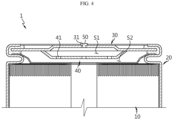
- FIG. 1 is a diagram showing the battery according to an embodiment of the present disclosure.
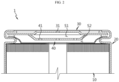
- FIG. 2 is a diagram showing the battery of FIG. 1 with a degassing portion for a degassing process.
- FIG. 3 is a diagram showing a vent flow of gas during the degassing process of the battery of the present disclosure.
- the battery 1 may include an electrode assembly 10, a housing 20, a cap 30 and a frame 40.
- the battery 1 of the present disclosure may be a rechargeable secondary battery.
- the battery 1 may be, for example, a cylindrical battery.
- the electrode assembly 10 may include a positive electrode and a negative electrode and a separator interposed between the positive electrode and the negative electrode.
- the electrode assembly 10 may be, for example, a jellyroll-type electrode assembly formed by winding a stack of the positive electrode, the negative electrode and the separator.
- the housing 20 may be configured to accommodate the electrode assembly 10 through an open portion on one side.
- the housing 20 may include a conductive metal.
- the housing 20 may accommodate an electrolyte solution together with the electrode assembly 10.
- the cap 30 may be configured to cover the open portion on one side of the housing 20.
- the cap 30 may include a metal.
- the frame 40 may be coupled to the inner surface of the cap 30, spaced apart from the cap 30 at least in part. When the frame 40 is coupled to the cap 30, a first space S1 may be formed between the cap 30 and the frame 40.
- the frame 40 may include a gas passing portion 41.
- the gas passing portion 41 may be configured to allow gas generated in a second space S2 accommodating the electrode assembly 10 to flow into the first space.
- the gas passing portion 41 may be, for example, a through-hole in the frame 40.
- the gas passing portion 41 may be one or more.
- the battery 1 since the battery 1 according to an embodiment of the present disclosure includes the frame 40 coupled to the inner surface of the cap 30, it may be possible to minimize electrolyte residues on the inner surface of the cap 30 due to movements of the electrolyte solution in the housing 20 in the process of manufacturing the battery 1. Since the frame 40 has the gas passing portion 41, gas generated in the housing 20 may go from the second space S2 to the first space S 1. Accordingly, the battery 1 of the present disclosure may be vented through the degassing portion 31 of the cap 30 at a location corresponding to the first space S1.
- the battery 1 of the present disclosure it may be possible to achieve proper venting of gas generated in the battery 1 through the activation process (see the gas vent path along the direction of the arrow in FIG. 3 ), and to prevent or minimize electrolyte leaks through the degassing portion 31 during gas venting.
- the degassing portion 31 of the cap 30 may be formed in advance in the manufacture of the cap 30, and alternatively, may be formed later for the degassing process.
- the frame 40 may be configured such that communication between the first space S1 and the second space S2 occurs only through the gas passing portion 41.
- the size of the gas passing portion 41 may be adjusted to allow gas generated in the second space S2 to smoothly pass through the gas passing portion 41 and keep the electrolyte solution from smoothly passing through the gas passing portion 41. Accordingly, it may be possible to prevent the electrolyte solution from moving to the degassing portion 31 of the cap 30 in the process of manufacturing the battery 1.
- the cap 30 may include the degassing portion 31 to vent gas generated in the housing 20.
- the degassing portion 31 may be formed in the manufacture of the cap 30, and may be formed later for the degassing process.
- the degassing portion 31 may be, for example, a through-hole in the cap 30.
- the degassing portion 31 may be formed at a location corresponding to the first space S1.
- FIG. 4 is a diagram showing the battery of FIG. 2 with the lid for closing the degassing portion after the degassing process is completed.
- FIG. 5 is a diagram showing the degassing portion of the battery of FIG. 2 closed by welding after the degassing process is completed.
- the battery 1 of the present disclosure may include the lid 50 for airtight closing of the degassing portion 31.
- the lid 50 may have a size corresponding to the degassing portion 31 to allow for airtight closing of the degassing portion 31 by an interference fit or screw coupling. That is, the lid 50 may be a different component from the cap 30.
- the lid 50 may be integrally formed with the cap 30 by welding the area in which the degassing portion 31 is formed after the degassing process of venting gas generated in the housing 20.
- the lid 50 is coupled to the degassing portion 31 by the welding, it may be possible to increase sealability of the housing 20.
- valve assembly 60 applied to the present disclosure will be described with reference to FIGS. 6 to 8 .
- FIG. 6 is a diagram showing the battery of FIG. 2 with the valve assembly for opening and closing the degassing portion.
- FIG. 7 is a diagram showing a vent flow of gas in the battery of FIG. 6 when the degassing portion is open.
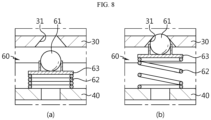
- FIG. 8 is a diagram showing the degassing portion in open and closed states by the operation of the valve assembly in the battery of FIG. 6 .
- the battery 1 may include the valve assembly 60.
- the valve assembly 60 may be applied instead of the lid 50.
- the valve assembly 60 may be disposed in the first space S1 and configured to open the degassing portion 31 during the degassing process of venting gas generated in the housing 20 and close the degassing portion 31 after the completion of the degassing process.
- the valve assembly 60 may include a closure 61 and an elastic member 62.
- the closure 61 may be configured to be inserted into the degassing portion 31 from the first space S1. In this case, the width at the outer end of the degassing portion 31 may be smaller than the maximum width of the closure 61 to prevent the closure 61 from slipping off from the battery 1.
- the closure 61 may be, for example, a spherical metal ball.
- the elastic member 62 may be disposed between the closure 61 and the frame 40 and configured to elastically press the closure 61 towards the degassing portion 31. That is, the elastic member 62 in compressed state may be interposed between the closure 61 and the frame 40.
- the elastic member 62 may be, for example, a spring.
- the valve assembly 60 may further include a fixing member 63 interposed between the closure 61 and the elastic member 62.
- the fixing member 63 may be configured to support the closure 61 on one side and be supported by the elastic member 62 on the other side.
- One side of the fixing member 63 may be coupled to the closure 61.
- the other side of the fixing member 63 may be coupled to the elastic member 62.
- the degassing portion 31 of the cap 30 may be opened by applying the pressure to the closure 61 in a direction of compressing the elastic member 62.
- gas in the battery 1 may exit the battery 1 along the direction of the arrow as shown in FIG. 7 . That is, in the degassing process, the degassing portion 31 may be opened by applying the pressure to the closure 61 from the outside of the degassing portion 31, and when the external negative force is applied to the open degassing portion 31, gas in the battery 1 may be vented.
- FIG. 8 it shows that the pressure is applied to the closure 61 and the elastic member 62 is compressed, then the degassing portion 31 is open (see FIG. 8(a) ), and when the pressure is removed from the closure 61, the degassing portion 31 is closed by the closure 61 (see FIG. 8(b) ).
- the degassing portion 31 may be reversibly open and closed by compressions and stretches of the elastic member 62. Accordingly, there is no need to perform an additional process for closing the degassing portion 31 after the degassing process.
- FIG. 9 is a diagram showing the cap having the vent in the battery module according to an embodiment of the present disclosure.
- the cap 30 may have the vent 32.
- the vent 32 may be configured to rupture when the internal pressure of the housing 20 increases.
- the vent 32 may be a portion of the cap 30 that is more vulnerable than any other surrounding area.
- the vent 32 may be, for example, an area having a smaller thickness than the remaining area of the cap 30.
- the vent 32 may be, for example, a notched area in one or two surfaces of the cap 30.
- the vent 32 may extend in the shape of a closed loop around the center of the cap 30.
- the vent 32 may be formed continuously or discontinuously.
- the vent 32 it may be possible to prevent a rise in the internal pressure of the battery 1 above a predetermined level when defects or failures occur in the battery 1.
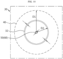
- FIG. 10 is a diagram showing the location at which the vent is formed and the location at which the frame and the cap are coupled, in the battery module of FIG. 9 .
- a distance D1 from the center of the cap 30 to the coupled part of the frame 40 and the cap 30 may be larger than a distance D2 from the center of the cap 30 to the vent 32.
- the weight of the frame 40 may hinder a portion of the cap 30 from being removed by the rupture of the vent 32.
- timely gas venting may fail.
- the internal pressure of the battery 1 abnormally increases, it may be possible to prevent the rupture pressure of the vent 32 from deviating from the design value by the weight of the frame 40, thereby improving safety of the battery 1 while in use.
- FIG. 11 is a diagram showing the frame of the present disclosure having an insulation layer.
- the frame 40 may have the insulation layer 42 on a first surface facing the electrode assembly 10.
- the cap 30 may include a metal to ensure strength, and in this case, the frame 40 may also include a metal for weld coupling with the cap 30.
- the frame 40 When the frame 40 includes a metal and has conductive properties, unnecessary electrical contact may occur between the frame 40 and the electrode assembly 10 or between the frame 40 and other metal component.
- the frame 40 has the insulation layer 42 as described above, it may be possible to prevent the unnecessary electrical contact.
- the insulation layer 42 may be, for example, formed by coating an insulating paint on the first surface of the frame 40.
- the cap 30 may not be polar.
- the cap 30 may be electrically insulated from the housing 20, and also electrically insulated from the electrode assembly 10.
- the cap 30 is not polar, it may be possible to prevent the occurrence and/or propagation of thermal events due to the contact between high temperature gas and polar components in the process of venting high temperature gas through the degassing portion 31 of the cap 30 and/or venting high temperature gas by the rupture of the vent 32.
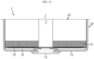
- FIG. 12 is a diagram showing a structure of a lower portion of the battery module according to an embodiment of the present disclosure.
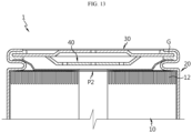
- FIG. 13 is a diagram showing a structure of an upper portion of the battery module according to an embodiment of the present disclosure.
- the battery 1 of the present disclosure may include a terminal T1 electrically connected to the electrode assembly 10.
- the terminal T1 may be, for example, electrically connected to a first uncoated portion 11 of the electrode assembly 10.
- the terminal T1 may be exposed to the outside of the housing 20 through a closed portion opposite the open portion of the housing 20.
- the electrical connection between the terminal T1 and the electrode assembly 10 may be established through a first current collector P1.
- the housing 20 may be electrically connected to a second uncoated portion 12 of the electrode assembly 10.
- the electrical connection between the housing 20 and the electrode assembly 10 may be established through a second current collector P2.
- An insulator IS for insulation may be interposed between the electrode assembly 10 and the closed portion of the housing 20 or between the first current collector P1 and the closed portion of the housing 20.
- a gasket for insulation and sealing may be interposed between the terminal T1 and the housing 20.
- a gasket G for insulation and sealing may be interposed between the cap 30 and the housing 20.
- the battery 1 of the present disclosure may use the terminal T1 as a first electrode terminal and the entire closed portion of the housing 20 as a second electrode terminal T2.
- FIG. 14 is a diagram showing the battery pack according to an embodiment of the present disclosure.
- the battery pack 3 may include at least one battery 1 of the present disclosure.
- the battery 1 may be accommodated in a pack housing 2.
- the battery pack 3 may include a component for electrical connection of the batteries 1 and/or a Battery management system (BMS) to control the charge and discharge of the battery 1.
- BMS Battery management system
- FIG. 15 is a diagram showing the vehicle according to an embodiment of the present disclosure.
- the vehicle 5 includes at least one battery pack 3.
- the vehicle 5 may be powered by the battery pack 3.
- the vehicle 5 may be, for example, a hybrid electric vehicle (HEV) or an electric vehicle (EV).
- HEV hybrid electric vehicle
- EV electric vehicle
Landscapes
- Chemical & Material Sciences (AREA)
- Chemical Kinetics & Catalysis (AREA)
- Electrochemistry (AREA)
- General Chemical & Material Sciences (AREA)
- Engineering & Computer Science (AREA)
- Aviation & Aerospace Engineering (AREA)
- Gas Exhaust Devices For Batteries (AREA)
- Battery Mounting, Suspending (AREA)
Abstract
Description
- The present disclosure relates to a battery, a battery pack including the same and a vehicle including the battery pack.
- The present application claims priority to
Korean Patent Application No. 10-2022-0089124 filed on July 19, 2022 Korean Patent Application No. 10-2022-0089123 filed on July 19, 2022 Korean Patent Application No. 10-2023-0087994 filed on July 6, 2023 - Secondary batteries undergo a charge/discharge process for activation in the manufacturing process and a degassing process to vent gas generated in the secondary batteries during charging/discharging.
- The degassing process of a secondary battery may be performed by applying a negative pressure to a partial open portion of the secondary battery. For example, after partially opening a side of the secondary battery having a hermetically sealed structure, the secondary battery may be placed in a chamber in which the negative pressure is formed. In this case, gas may be vented through the open portion of the secondary battery.
- In the process of removing gas generated in the secondary battery, when gas is vented by the negative pressure, electrolyte leaks may occur in the secondary battery.
- Moreover, in the process of manufacturing the secondary battery, the secondary battery may be transported while standing, lying and upside down, and in this process, electrolyte stains may appear on the inner wall of a housing. In this case, when the negative pressure is applied to the open portion of the secondary battery, the electrolyte stains around the open portion may leak out.
- Alternatively, the secondary battery may be placed in a specific direction during transportation, but also in this case, electrolyte stains may appear around the open portion for the degassing process due to movements of electrolyte solutions during transportation. When the negative pressure is applied to the open portion for the degassing process, the electrolyte stains around the open portion may leak out.
- Accordingly, there is a need for the development of batteries having a structure for minimizing electrolyte stains around the open portion for the degassing process in the manufacturing process.
- The present disclosure is designed to address the above-described problem, and therefore the present disclosure is directed to providing a battery having a structure for minimizing electrolyte stains around an open portion for a degassing process in the manufacturing process.
- However, the technical problem to be solved by the present disclosure is not limited to the above-described problems, and these and other problems will be clearly understood by those skilled in the art from the following description.
- To solve the above-described problem, a battery according to an embodiment of the present disclosure includes an electrode assembly; a housing accommodating the electrode assembly through an open portion on a side; a cap covering the open portion; and a frame including a gas passing portion configured to allow gas generated in a second space accommodating the electrode assembly to flow into a first space, wherein the first space is formed when the frame is coupled to an inner surface of the cap, spaced apart from the cap at least in part.
- The frame may be configured such that communication between the first space and the second space occurs only through the gas passing portion.
- The cap may include a degassing portion configured to vent gas generated in the housing.
- The battery may include a lid for airtight closing of the degassing portion.
- The lid may be integrally formed with the cap by welding an area in which the degassing portion is formed after a degassing process of venting the gas generated in the housing.
- The battery may include a valve assembly disposed in the first space and configured to open the degassing portion during a degassing process of venting the gas generated in the housing and close the degassing portion after completion of the degassing process.
- The valve assembly may include a closure configured to be inserted into the degassing portion from the first space; and an elastic member disposed between the closure and the frame and configured to elastically press the closure towards the degassing portion.
- The cap may have a vent configured to rupture when an internal pressure of the housing increases.
- A distance from a center of the cap to a coupled part of the frame and the cap may be larger than a distance from the center of the cap to the vent.
- The frame may have an insulation layer on a first surface facing the electrode assembly.
- The cap may not be polar.
- The battery may include a terminal electrically connected to the electrode assembly.
- The battery may include a current collector coupled to a side of the electrode assembly and configured to electrically connect the electrode assembly to the housing.
- To solve the above-described problem, a battery pack according to an embodiment of the present disclosure includes the battery according to an embodiment of the present disclosure.
- To solve the above-described problem, a vehicle according to an embodiment of the present disclosure includes the battery pack according to an embodiment of the present disclosure.
- According to an aspect of the present disclosure, it may be possible to minimize electrolyte stains around the open portion for the degassing process in the manufacturing process.
- However, the advantageous effects obtained through the present disclosure are not limited to the above-described effects, and these and other advantageous effects will be clearly understood by those skilled in the art from the following description.
- The accompanying drawings illustrate exemplary embodiments of the present disclosure and together with the following detailed description, serve to provide a further understanding of the technical aspect of the present disclosure, and thus the present disclosure should not be construed as being limited to the drawings.
-
FIG. 1 is a diagram showing a battery according to an embodiment of the present disclosure. -
FIG. 2 is a diagram showing the battery ofFIG. 1 with a degassing portion for a degassing process. -
FIG. 3 is a diagram showing a vent flow of gas during a degassing process of a battery of the present disclosure. -
FIG. 4 is a diagram showing the battery ofFIG. 2 with a lid for closing a degassing portion after a degassing process is completed. -
FIG. 5 is a diagram showing a degassing portion of the battery ofFIG. 2 closed by welding after a degassing process is completed. -
FIG. 6 is a diagram showing the battery ofFIG. 2 with a valve assembly for opening and closing a degassing portion. -
FIG. 7 is a diagram showing a vent flow of gas in the battery ofFIG. 6 when a degassing portion is open. -
FIG. 8 is a diagram showing a degassing portion in open and closed states by the operation of a valve assembly in the battery ofFIG. 6 . -
FIG. 9 is a diagram showing a cap having a vent in a battery module according to an embodiment of the present disclosure. -
FIG. 10 is a diagram showing a location at which a vent is formed and a location at which a frame and a cap are coupled, in the battery module ofFIG. 9 . -
FIG. 11 is a diagram showing a frame of the present disclosure having an insulation layer. -
FIG. 12 is a diagram showing a structure of a lower portion of a battery module according to an embodiment of the present disclosure. -
FIG. 13 is a diagram showing a structure of an upper portion of a battery module according to an embodiment of the present disclosure. -
FIG. 14 is a diagram showing a battery pack according to an embodiment of the present disclosure. -
FIG. 15 is a diagram showing a vehicle according to an embodiment of the present disclosure. - Hereinafter, exemplary embodiments of the present disclosure will be described in detail with reference to the accompanying drawings. Prior to the description, it should be understood that the terms or words used in the specification and the appended claims should not be construed as being limited to general and dictionary meanings, but rather interpreted based on the meanings and concepts corresponding to the technical aspect of the present disclosure on the basis of the principle that the inventor is allowed to define the terms appropriately for the best explanation. Therefore, the embodiments described herein and the illustrations shown in the drawings are exemplary embodiments of the present disclosure to describe the technical aspect of the present disclosure and are not intended to be limiting, so it should be understood that a variety of other equivalents and modifications could have been made thereto at the time that the application was filed.
- The structure of a battery according to an embodiment of the present disclosure will be described with reference to
FIGS. 1 to 3 .FIG. 1 is a diagram showing the battery according to an embodiment of the present disclosure.FIG. 2 is a diagram showing the battery ofFIG. 1 with a degassing portion for a degassing process.FIG. 3 is a diagram showing a vent flow of gas during the degassing process of the battery of the present disclosure. - Referring to
FIGS. 1 to 3 , thebattery 1 according to an embodiment of the present disclosure may include anelectrode assembly 10, ahousing 20, acap 30 and aframe 40. Thebattery 1 of the present disclosure may be a rechargeable secondary battery. Thebattery 1 may be, for example, a cylindrical battery. - The
electrode assembly 10 may include a positive electrode and a negative electrode and a separator interposed between the positive electrode and the negative electrode. Theelectrode assembly 10 may be, for example, a jellyroll-type electrode assembly formed by winding a stack of the positive electrode, the negative electrode and the separator. Thehousing 20 may be configured to accommodate theelectrode assembly 10 through an open portion on one side. Thehousing 20 may include a conductive metal. Thehousing 20 may accommodate an electrolyte solution together with theelectrode assembly 10. Thecap 30 may be configured to cover the open portion on one side of thehousing 20. Thecap 30 may include a metal. - The
frame 40 may be coupled to the inner surface of thecap 30, spaced apart from thecap 30 at least in part. When theframe 40 is coupled to thecap 30, a first space S1 may be formed between thecap 30 and theframe 40. - The
frame 40 may include agas passing portion 41. Thegas passing portion 41 may be configured to allow gas generated in a second space S2 accommodating theelectrode assembly 10 to flow into the first space. Thegas passing portion 41 may be, for example, a through-hole in theframe 40. Thegas passing portion 41 may be one or more. - As described above, since the
battery 1 according to an embodiment of the present disclosure includes theframe 40 coupled to the inner surface of thecap 30, it may be possible to minimize electrolyte residues on the inner surface of thecap 30 due to movements of the electrolyte solution in thehousing 20 in the process of manufacturing thebattery 1. Since theframe 40 has thegas passing portion 41, gas generated in thehousing 20 may go from the second space S2 to thefirst space S 1. Accordingly, thebattery 1 of the present disclosure may be vented through the degassingportion 31 of thecap 30 at a location corresponding to the first space S1. - As described above, according to the
battery 1 of the present disclosure, it may be possible to achieve proper venting of gas generated in thebattery 1 through the activation process (see the gas vent path along the direction of the arrow inFIG. 3 ), and to prevent or minimize electrolyte leaks through the degassingportion 31 during gas venting. - In the present disclosure, the degassing
portion 31 of thecap 30 may be formed in advance in the manufacture of thecap 30, and alternatively, may be formed later for the degassing process. - The
frame 40 may be configured such that communication between the first space S1 and the second space S2 occurs only through thegas passing portion 41. In this case, the size of thegas passing portion 41 may be adjusted to allow gas generated in the second space S2 to smoothly pass through thegas passing portion 41 and keep the electrolyte solution from smoothly passing through thegas passing portion 41. Accordingly, it may be possible to prevent the electrolyte solution from moving to the degassingportion 31 of thecap 30 in the process of manufacturing thebattery 1. - The
cap 30 may include the degassingportion 31 to vent gas generated in thehousing 20. As described above, the degassingportion 31 may be formed in the manufacture of thecap 30, and may be formed later for the degassing process. The degassingportion 31 may be, for example, a through-hole in thecap 30. The degassingportion 31 may be formed at a location corresponding to the first space S1. - Subsequently, a
lid 50 applied to thebattery 1 of the present disclosure will be described with reference toFIGS. 4 and5 . -
FIG. 4 is a diagram showing the battery ofFIG. 2 with the lid for closing the degassing portion after the degassing process is completed.FIG. 5 is a diagram showing the degassing portion of the battery ofFIG. 2 closed by welding after the degassing process is completed. - To begin with, referring to
FIG. 4 , thebattery 1 of the present disclosure may include thelid 50 for airtight closing of the degassingportion 31. Thelid 50 may have a size corresponding to the degassingportion 31 to allow for airtight closing of the degassingportion 31 by an interference fit or screw coupling. That is, thelid 50 may be a different component from thecap 30. - Alternatively, as shown in
FIG. 5 , thelid 50 may be integrally formed with thecap 30 by welding the area in which thedegassing portion 31 is formed after the degassing process of venting gas generated in thehousing 20. When thelid 50 is coupled to the degassingportion 31 by the welding, it may be possible to increase sealability of thehousing 20. - Subsequently, a
valve assembly 60 applied to the present disclosure will be described with reference toFIGS. 6 to 8 . -
FIG. 6 is a diagram showing the battery ofFIG. 2 with the valve assembly for opening and closing the degassing portion.FIG. 7 is a diagram showing a vent flow of gas in the battery ofFIG. 6 when the degassing portion is open.FIG. 8 is a diagram showing the degassing portion in open and closed states by the operation of the valve assembly in the battery ofFIG. 6 . - To begin with, referring to
FIG. 6 , thebattery 1 may include thevalve assembly 60. Thevalve assembly 60 may be applied instead of thelid 50. - The
valve assembly 60 may be disposed in the first space S1 and configured to open the degassingportion 31 during the degassing process of venting gas generated in thehousing 20 and close the degassingportion 31 after the completion of the degassing process. - The
valve assembly 60 may include aclosure 61 and anelastic member 62. Theclosure 61 may be configured to be inserted into the degassingportion 31 from the first space S1. In this case, the width at the outer end of the degassingportion 31 may be smaller than the maximum width of theclosure 61 to prevent theclosure 61 from slipping off from thebattery 1. Theclosure 61 may be, for example, a spherical metal ball. - The
elastic member 62 may be disposed between theclosure 61 and theframe 40 and configured to elastically press theclosure 61 towards the degassingportion 31. That is, theelastic member 62 in compressed state may be interposed between theclosure 61 and theframe 40. Theelastic member 62 may be, for example, a spring. - The
valve assembly 60 may further include a fixingmember 63 interposed between theclosure 61 and theelastic member 62. The fixingmember 63 may be configured to support theclosure 61 on one side and be supported by theelastic member 62 on the other side. One side of the fixingmember 63 may be coupled to theclosure 61. The other side of the fixingmember 63 may be coupled to theelastic member 62. - When the
battery 1 of the present disclosure includes thevalve assembly 60, the degassingportion 31 of thecap 30 may be opened by applying the pressure to theclosure 61 in a direction of compressing theelastic member 62. When the degassingportion 31 is open, gas in thebattery 1 may exit thebattery 1 along the direction of the arrow as shown inFIG. 7 . That is, in the degassing process, the degassingportion 31 may be opened by applying the pressure to theclosure 61 from the outside of the degassingportion 31, and when the external negative force is applied to theopen degassing portion 31, gas in thebattery 1 may be vented. - Referring to
FIG. 8 , it shows that the pressure is applied to theclosure 61 and theelastic member 62 is compressed, then the degassingportion 31 is open (seeFIG. 8(a) ), and when the pressure is removed from theclosure 61, the degassingportion 31 is closed by the closure 61 (seeFIG. 8(b) ). When thebattery 1 of the present disclosure includes thevalve assembly 60, the degassingportion 31 may be reversibly open and closed by compressions and stretches of theelastic member 62. Accordingly, there is no need to perform an additional process for closing the degassingportion 31 after the degassing process. - Subsequently, a
vent 32 of the present disclosure will be described with reference toFIG. 9. FIG. 9 is a diagram showing the cap having the vent in the battery module according to an embodiment of the present disclosure. - Referring to
FIG. 9 , thecap 30 may have thevent 32. Thevent 32 may be configured to rupture when the internal pressure of thehousing 20 increases. Thevent 32 may be a portion of thecap 30 that is more vulnerable than any other surrounding area. Thevent 32 may be, for example, an area having a smaller thickness than the remaining area of thecap 30. Thevent 32 may be, for example, a notched area in one or two surfaces of thecap 30. Thevent 32 may extend in the shape of a closed loop around the center of thecap 30. Thevent 32 may be formed continuously or discontinuously. - As described above, when the
battery 1 of the present disclosure has thevent 32, it may be possible to prevent a rise in the internal pressure of thebattery 1 above a predetermined level when defects or failures occur in thebattery 1. - Subsequently, a location of a coupled part of the
cap 30 and theframe 40 of the present disclosure will be described with reference toFIG. 10 together withFIG. 9 .FIG. 10 is a diagram showing the location at which the vent is formed and the location at which the frame and the cap are coupled, in the battery module ofFIG. 9 . - Referring to
FIGS. 9 and10 , in thebattery 1 of the present disclosure having thevent 32, a distance D1 from the center of thecap 30 to the coupled part of theframe 40 and thecap 30 may be larger than a distance D2 from the center of thecap 30 to thevent 32. - In the case where the coupled part of the
frame 40 and thecap 30 is located at an inner position than thevent 32, the weight of theframe 40 may hinder a portion of thecap 30 from being removed by the rupture of thevent 32. When the rupture of thevent 32 is hindered, timely gas venting may fail. According to the above-described configuration of the present disclosure, when the internal pressure of thebattery 1 abnormally increases, it may be possible to prevent the rupture pressure of thevent 32 from deviating from the design value by the weight of theframe 40, thereby improving safety of thebattery 1 while in use. - Subsequently, the insulation structure applied to the
frame 40 of the present disclosure will be described with reference toFIG. 11. FIG. 11 is a diagram showing the frame of the present disclosure having an insulation layer. - Referring to
FIG. 11 , theframe 40 may have theinsulation layer 42 on a first surface facing theelectrode assembly 10. Thecap 30 may include a metal to ensure strength, and in this case, theframe 40 may also include a metal for weld coupling with thecap 30. - When the
frame 40 includes a metal and has conductive properties, unnecessary electrical contact may occur between theframe 40 and theelectrode assembly 10 or between theframe 40 and other metal component. When theframe 40 has theinsulation layer 42 as described above, it may be possible to prevent the unnecessary electrical contact. Theinsulation layer 42 may be, for example, formed by coating an insulating paint on the first surface of theframe 40. - Meanwhile, in the
battery 1 of the present disclosure, thecap 30 may not be polar. To this end, thecap 30 may be electrically insulated from thehousing 20, and also electrically insulated from theelectrode assembly 10. When thecap 30 is not polar, it may be possible to prevent the occurrence and/or propagation of thermal events due to the contact between high temperature gas and polar components in the process of venting high temperature gas through the degassingportion 31 of thecap 30 and/or venting high temperature gas by the rupture of thevent 32. - Subsequently, the electrical connection structure and the hermetically sealed structure of the
battery 1 will be described with reference toFIGS. 12 and13 .FIG. 12 is a diagram showing a structure of a lower portion of the battery module according to an embodiment of the present disclosure.FIG. 13 is a diagram showing a structure of an upper portion of the battery module according to an embodiment of the present disclosure. - Referring to
FIGS. 12 and13 , thebattery 1 of the present disclosure may include a terminal T1 electrically connected to theelectrode assembly 10. The terminal T1 may be, for example, electrically connected to a firstuncoated portion 11 of theelectrode assembly 10. The terminal T1 may be exposed to the outside of thehousing 20 through a closed portion opposite the open portion of thehousing 20. The electrical connection between the terminal T1 and theelectrode assembly 10 may be established through a first current collector P1. Thehousing 20 may be electrically connected to a seconduncoated portion 12 of theelectrode assembly 10. The electrical connection between thehousing 20 and theelectrode assembly 10 may be established through a second current collector P2. - An insulator IS for insulation may be interposed between the
electrode assembly 10 and the closed portion of thehousing 20 or between the first current collector P1 and the closed portion of thehousing 20. A gasket for insulation and sealing may be interposed between the terminal T1 and thehousing 20. A gasket G for insulation and sealing may be interposed between thecap 30 and thehousing 20. - By the electrical connection structure, the
battery 1 of the present disclosure may use the terminal T1 as a first electrode terminal and the entire closed portion of thehousing 20 as a second electrode terminal T2. - Subsequently, a
battery pack 3 according to an embodiment of the present disclosure will be described with reference toFIG. 14. FIG. 14 is a diagram showing the battery pack according to an embodiment of the present disclosure. - Referring to
FIG. 14 , thebattery pack 3 according to an embodiment of the present disclosure may include at least onebattery 1 of the present disclosure. Thebattery 1 may be accommodated in apack housing 2. Thebattery pack 3 may include a component for electrical connection of thebatteries 1 and/or a Battery management system (BMS) to control the charge and discharge of thebattery 1. - Subsequently, a vehicle 5 according to an embodiment of the present disclosure will be described with reference to 15.
FIG. 15 is a diagram showing the vehicle according to an embodiment of the present disclosure. - Referring to
FIG. 15 , the vehicle 5 according to an embodiment of the present disclosure includes at least onebattery pack 3. The vehicle 5 may be powered by thebattery pack 3. The vehicle 5 may be, for example, a hybrid electric vehicle (HEV) or an electric vehicle (EV). - While the present disclosure has been hereinabove described with regard to a limited number of embodiments and drawings, the present disclosure is not limited thereto and it is apparent that a variety of changes and modifications may be made by those skilled in the art within the technical aspect of the present disclosure and the scope of the appended claims and their equivalents.
-
- 1:
- Battery
- 2:
- Pack housing
- 3:
- Battery pack
- 5:
- Vehicle
- 10:
- Electrode assembly
- 11:
- First uncoated portion
- 12:
- Second uncoated portion
- 20:
- Housing
- 30:
- Cap
- 31:
- Degassing portion
- 32:
- Vent
- 40:
- Frame
- 41:
- Gas passing portion
- 42:
- Insulation layer
- 50:
- Lid
- 60:
- Valve assembly
- 61:
- Closure
- 62:
- Elastic member
- 63:
- Fixing member
Claims (15)
- A battery, comprising:an electrode assembly;a housing accommodating the electrode assembly through an open portion on a side;a cap covering the open portion; anda frame including a gas passing portion configured to allow gas generated in a second space accommodating the electrode assembly to flow into a first space, wherein the first space is formed when the frame is coupled to an inner surface of the cap, spaced apart from the cap at least in part.
- The battery according to claim 1, wherein the frame is configured such that communication between the first space and the second space occurs only through the gas passing portion.
- The battery according to claim 1, wherein the cap includes a degassing portion configured to vent gas generated in the housing.
- The battery according to claim 3, comprising:
a lid for airtight closing of the degassing portion. - The battery according to claim 4, wherein the lid is integrally formed with the cap by welding an area in which the degassing portion is formed after a degassing process of venting the gas generated in the housing.
- The battery according to claim 3, comprising:
a valve assembly disposed in the first space and configured to open the degassing portion during a degassing process of venting the gas generated in the housing and close the degassing portion after completion of the degassing process. - The battery according to claim 6, wherein the valve assembly includes:a closure configured to be inserted into the degassing portion from the first space; andan elastic member disposed between the closure and the frame and configured to elastically press the closure towards the degassing portion.
- The battery according to claim 1, wherein the cap has a vent configured to rupture when an internal pressure of the housing increases.
- The battery according to claim 8, wherein a distance from a center of the cap to a coupled part of the frame and the cap is larger than a distance from the center of the cap to the vent.
- The battery according to claim 1, wherein the frame has an insulation layer on a first surface facing the electrode assembly.
- The battery according to claim 1, wherein the cap is not polar.
- The battery according to claim 1, comprising:
a terminal electrically connected to the electrode assembly. - The battery according to claim 12, comprising:
a current collector coupled to a side of the electrode assembly and configured to electrically connect the electrode assembly to the housing. - A battery pack comprising the battery according to any one of claims 1 to 13.
- A vehicle comprising the battery pack according to claim 14.
Applications Claiming Priority (4)
| Application Number | Priority Date | Filing Date | Title |
|---|---|---|---|
| KR20220089124 | 2022-07-19 | ||
| KR20220089123 | 2022-07-19 | ||
| KR1020230087994A KR102913957B1 (en) | 2022-07-19 | 2023-07-06 | A battery, a battery pack including the battery, and a vehicle including the battery pack |
| PCT/KR2023/010449 WO2024019550A1 (en) | 2022-07-19 | 2023-07-19 | Battery, battery pack including battery, and vehicle comprising battery pack |
Publications (2)
| Publication Number | Publication Date |
|---|---|
| EP4496099A1 true EP4496099A1 (en) | 2025-01-22 |
| EP4496099A4 EP4496099A4 (en) | 2025-12-03 |
Family
ID=89618271
Family Applications (1)
| Application Number | Title | Priority Date | Filing Date |
|---|---|---|---|
| EP23843396.5A Pending EP4496099A4 (en) | 2022-07-19 | 2023-07-19 | BATTERY, BATTERY PACK WITH THE BATTERY AND VEHICLE WITH THE BATTERY PACK |
Country Status (5)
| Country | Link |
|---|---|
| EP (1) | EP4496099A4 (en) |
| JP (1) | JP2025524689A (en) |
| CN (1) | CN119174039A (en) |
| CA (1) | CA3251291A1 (en) |
| WO (1) | WO2024019550A1 (en) |
Family Cites Families (16)
| Publication number | Priority date | Publication date | Assignee | Title |
|---|---|---|---|---|
| KR100369068B1 (en) * | 1999-04-16 | 2003-01-24 | 삼성에스디아이 주식회사 | Cylinder-shaped secondary battery |
| WO2006004143A1 (en) * | 2004-07-02 | 2006-01-12 | Toyota Jidosha Kabushiki Kaisha | Nickel-hydrogen accumulator battery |
| JP2013175280A (en) * | 2010-06-11 | 2013-09-05 | Panasonic Corp | Secondary battery |
| CN103081164B (en) * | 2010-08-06 | 2015-11-25 | 松下知识产权经营株式会社 | Battery module |
| JP5903607B2 (en) * | 2011-11-11 | 2016-04-13 | パナソニックIpマネジメント株式会社 | Battery pack |
| CN104067404B (en) * | 2012-02-24 | 2016-04-27 | 松下知识产权经营株式会社 | Drum like alkaline accumulator |
| JP2015106490A (en) * | 2013-11-29 | 2015-06-08 | 三菱自動車工業株式会社 | Secondary battery with safety valve |
| KR101828126B1 (en) * | 2015-05-22 | 2018-02-09 | 주식회사 엘지화학 | Cap assembly |
| KR101919947B1 (en) * | 2016-11-28 | 2018-11-20 | 삼화콘덴서공업 주식회사 | Cylinder type battery |
| KR102198047B1 (en) * | 2017-11-01 | 2021-01-04 | 삼성에스디아이 주식회사 | Rechargeable battery |
| JP7607214B2 (en) * | 2020-01-31 | 2024-12-27 | パナソニックIpマネジメント株式会社 | Power storage device |
| US20230318120A1 (en) * | 2020-09-25 | 2023-10-05 | Panasonic intellectual property Management co., Ltd | Battery pack and instrument having function of discharging gas from battery pack |
| JP7249983B2 (en) * | 2020-11-16 | 2023-03-31 | プライムプラネットエナジー&ソリューションズ株式会社 | Method for manufacturing sealed battery |
| KR20220089124A (en) | 2020-12-21 | 2022-06-28 | 금오공과대학교 산학협력단 | 50um High Gap Modulator Mount |
| KR102468078B1 (en) | 2020-12-21 | 2022-11-16 | 주식회사 포스코 | Non-oriented electrical steel sheet and method for manufacturing the same |
| KR20230087994A (en) | 2021-12-10 | 2023-06-19 | 빛그린전기차협동조합 | Hybrid steering system for automobiles |
-
2023
- 2023-07-19 WO PCT/KR2023/010449 patent/WO2024019550A1/en not_active Ceased
- 2023-07-19 JP JP2025502677A patent/JP2025524689A/en active Pending
- 2023-07-19 CN CN202380039408.7A patent/CN119174039A/en active Pending
- 2023-07-19 EP EP23843396.5A patent/EP4496099A4/en active Pending
- 2023-07-19 CA CA3251291A patent/CA3251291A1/en active Pending
Also Published As
| Publication number | Publication date |
|---|---|
| CA3251291A1 (en) | 2025-03-17 |
| CN119174039A (en) | 2024-12-20 |
| JP2025524689A (en) | 2025-07-30 |
| EP4496099A4 (en) | 2025-12-03 |
| WO2024019550A1 (en) | 2024-01-25 |
Similar Documents
| Publication | Publication Date | Title |
|---|---|---|
| KR102198047B1 (en) | Rechargeable battery | |
| CN105789493B (en) | Rechargeable battery and rechargeable battery pack | |
| CN102088103B (en) | Rechargeable battery | |
| KR100467698B1 (en) | Cylindrical type lithium secondary battery and the fabrication method of the same | |
| KR20130089134A (en) | Rechargeable battery | |
| EP3062368B1 (en) | Rechargeable battery | |
| EP3062367B1 (en) | Rechargeable battery | |
| US20260106349A1 (en) | Secondary battery | |
| CN111989801A (en) | Secondary battery | |
| KR102299243B1 (en) | Rechargeable battery | |
| KR20150105849A (en) | Rechargeable battery having insulating member | |
| US20230223643A1 (en) | Secondary battery | |
| KR20110082975A (en) | Secondary battery | |
| KR100277652B1 (en) | Cap Assembly of Secondary Battery | |
| US20240145871A1 (en) | Power storage cell | |
| CA3251291A1 (en) | Battery, battery pack including the same, and vehicle including the battery pack | |
| KR20180051209A (en) | Rechargeable battery pack | |
| KR102913957B1 (en) | A battery, a battery pack including the battery, and a vehicle including the battery pack | |
| KR20180054278A (en) | Rechargeable battery | |
| KR20230009049A (en) | Secondary Battery | |
| JPH11283600A (en) | Sealed battery | |
| KR100624968B1 (en) | Cap assembly and a lithium ion secondary battery having the same | |
| US20230238621A1 (en) | Secondary battery | |
| US20240128559A1 (en) | Method of manufacturing power storage cell and power storage cell | |
| US20240128617A1 (en) | Power storage cell |
Legal Events
| Date | Code | Title | Description |
|---|---|---|---|
| STAA | Information on the status of an ep patent application or granted ep patent |
Free format text: STATUS: THE INTERNATIONAL PUBLICATION HAS BEEN MADE |
|
| PUAI | Public reference made under article 153(3) epc to a published international application that has entered the european phase |
Free format text: ORIGINAL CODE: 0009012 |
|
| STAA | Information on the status of an ep patent application or granted ep patent |
Free format text: STATUS: REQUEST FOR EXAMINATION WAS MADE |
|
| 17P | Request for examination filed |
Effective date: 20241018 |
|
| AK | Designated contracting states |
Kind code of ref document: A1 Designated state(s): AL AT BE BG CH CY CZ DE DK EE ES FI FR GB GR HR HU IE IS IT LI LT LU LV MC ME MK MT NL NO PL PT RO RS SE SI SK SM TR |
|
| DAV | Request for validation of the european patent (deleted) | ||
| DAX | Request for extension of the european patent (deleted) | ||
| A4 | Supplementary search report drawn up and despatched |
Effective date: 20251104 |
|
| RIC1 | Information provided on ipc code assigned before grant |
Ipc: H01M 50/333 20210101AFI20251029BHEP Ipc: H01M 50/392 20210101ALI20251029BHEP Ipc: H01M 50/152 20210101ALI20251029BHEP Ipc: H01M 50/342 20210101ALI20251029BHEP Ipc: H01M 50/213 20210101ALI20251029BHEP Ipc: H01M 50/249 20210101ALI20251029BHEP Ipc: H01M 10/04 20060101ALI20251029BHEP |