EP4496098A1 - Power supply device and lead holding structure - Google Patents
Power supply device and lead holding structure Download PDFInfo
- Publication number
- EP4496098A1 EP4496098A1 EP23770375.6A EP23770375A EP4496098A1 EP 4496098 A1 EP4496098 A1 EP 4496098A1 EP 23770375 A EP23770375 A EP 23770375A EP 4496098 A1 EP4496098 A1 EP 4496098A1
- Authority
- EP
- European Patent Office
- Prior art keywords
- lead wire
- circuit board
- main surface
- tip end
- cut
- Prior art date
- Legal status (The legal status is an assumption and is not a legal conclusion. Google has not performed a legal analysis and makes no representation as to the accuracy of the status listed.)
- Pending
Links
Images






Classifications
-
- H—ELECTRICITY
- H05—ELECTRIC TECHNIQUES NOT OTHERWISE PROVIDED FOR
- H05K—PRINTED CIRCUITS; CASINGS OR CONSTRUCTIONAL DETAILS OF ELECTRIC APPARATUS; MANUFACTURE OF ASSEMBLAGES OF ELECTRICAL COMPONENTS
- H05K7/00—Constructional details common to different types of electric apparatus
- H05K7/14—Mounting supporting structure in casing or on frame or rack
- H05K7/1422—Printed circuit boards receptacles, e.g. stacked structures, electronic circuit modules or box like frames
- H05K7/1427—Housings
- H05K7/1432—Housings specially adapted for power drive units or power converters
- H05K7/14327—Housings specially adapted for power drive units or power converters having supplementary functional units, e.g. data transfer modules or displays or user interfaces
-
- H—ELECTRICITY
- H01—ELECTRIC ELEMENTS
- H01M—PROCESSES OR MEANS, e.g. BATTERIES, FOR THE DIRECT CONVERSION OF CHEMICAL ENERGY INTO ELECTRICAL ENERGY
- H01M50/00—Constructional details or processes of manufacture of the non-active parts of electrochemical cells other than fuel cells, e.g. hybrid cells
- H01M50/20—Mountings; Secondary casings or frames; Racks, modules or packs; Suspension devices; Shock absorbers; Transport or carrying devices; Holders
- H01M50/298—Mountings; Secondary casings or frames; Racks, modules or packs; Suspension devices; Shock absorbers; Transport or carrying devices; Holders characterised by the wiring of battery packs
-
- H—ELECTRICITY
- H01—ELECTRIC ELEMENTS
- H01M—PROCESSES OR MEANS, e.g. BATTERIES, FOR THE DIRECT CONVERSION OF CHEMICAL ENERGY INTO ELECTRICAL ENERGY
- H01M50/00—Constructional details or processes of manufacture of the non-active parts of electrochemical cells other than fuel cells, e.g. hybrid cells
- H01M50/20—Mountings; Secondary casings or frames; Racks, modules or packs; Suspension devices; Shock absorbers; Transport or carrying devices; Holders
- H01M50/204—Racks, modules or packs for multiple batteries or multiple cells
- H01M50/207—Racks, modules or packs for multiple batteries or multiple cells characterised by their shape
- H01M50/213—Racks, modules or packs for multiple batteries or multiple cells characterised by their shape adapted for cells having curved cross-section, e.g. round or elliptic
-
- H—ELECTRICITY
- H01—ELECTRIC ELEMENTS
- H01M—PROCESSES OR MEANS, e.g. BATTERIES, FOR THE DIRECT CONVERSION OF CHEMICAL ENERGY INTO ELECTRICAL ENERGY
- H01M50/00—Constructional details or processes of manufacture of the non-active parts of electrochemical cells other than fuel cells, e.g. hybrid cells
- H01M50/20—Mountings; Secondary casings or frames; Racks, modules or packs; Suspension devices; Shock absorbers; Transport or carrying devices; Holders
- H01M50/284—Mountings; Secondary casings or frames; Racks, modules or packs; Suspension devices; Shock absorbers; Transport or carrying devices; Holders with incorporated circuit boards, e.g. printed circuit boards [PCB]
-
- H—ELECTRICITY
- H05—ELECTRIC TECHNIQUES NOT OTHERWISE PROVIDED FOR
- H05K—PRINTED CIRCUITS; CASINGS OR CONSTRUCTIONAL DETAILS OF ELECTRIC APPARATUS; MANUFACTURE OF ASSEMBLAGES OF ELECTRICAL COMPONENTS
- H05K1/00—Printed circuits
- H05K1/02—Details
- H05K1/14—Structural association of two or more printed circuits
- H05K1/144—Stacked arrangements of planar printed circuit boards
-
- H—ELECTRICITY
- H05—ELECTRIC TECHNIQUES NOT OTHERWISE PROVIDED FOR
- H05K—PRINTED CIRCUITS; CASINGS OR CONSTRUCTIONAL DETAILS OF ELECTRIC APPARATUS; MANUFACTURE OF ASSEMBLAGES OF ELECTRICAL COMPONENTS
- H05K2201/00—Indexing scheme relating to printed circuits covered by H05K1/00
- H05K2201/04—Assemblies of printed circuits
- H05K2201/042—Stacked spaced PCBs; Planar parts of folded flexible circuits having mounted components in between or spaced from each other
-
- H—ELECTRICITY
- H05—ELECTRIC TECHNIQUES NOT OTHERWISE PROVIDED FOR
- H05K—PRINTED CIRCUITS; CASINGS OR CONSTRUCTIONAL DETAILS OF ELECTRIC APPARATUS; MANUFACTURE OF ASSEMBLAGES OF ELECTRICAL COMPONENTS
- H05K2201/00—Indexing scheme relating to printed circuits covered by H05K1/00
- H05K2201/09—Shape and layout
- H05K2201/09009—Substrate related
- H05K2201/09036—Recesses or grooves in insulating substrate
-
- H—ELECTRICITY
- H05—ELECTRIC TECHNIQUES NOT OTHERWISE PROVIDED FOR
- H05K—PRINTED CIRCUITS; CASINGS OR CONSTRUCTIONAL DETAILS OF ELECTRIC APPARATUS; MANUFACTURE OF ASSEMBLAGES OF ELECTRICAL COMPONENTS
- H05K2201/00—Indexing scheme relating to printed circuits covered by H05K1/00
- H05K2201/10—Details of components or other objects attached to or integrated in a printed circuit board
- H05K2201/10227—Other objects, e.g. metallic pieces
- H05K2201/10356—Cables
-
- Y—GENERAL TAGGING OF NEW TECHNOLOGICAL DEVELOPMENTS; GENERAL TAGGING OF CROSS-SECTIONAL TECHNOLOGIES SPANNING OVER SEVERAL SECTIONS OF THE IPC; TECHNICAL SUBJECTS COVERED BY FORMER USPC CROSS-REFERENCE ART COLLECTIONS [XRACs] AND DIGESTS
- Y02—TECHNOLOGIES OR APPLICATIONS FOR MITIGATION OR ADAPTATION AGAINST CLIMATE CHANGE
- Y02E—REDUCTION OF GREENHOUSE GAS [GHG] EMISSIONS, RELATED TO ENERGY GENERATION, TRANSMISSION OR DISTRIBUTION
- Y02E60/00—Enabling technologies; Technologies with a potential or indirect contribution to GHG emissions mitigation
- Y02E60/10—Energy storage using batteries
Definitions
- the present disclosure relates to a power supply device and a lead holding structure.
- Power supply devices including battery cells connected in series or parallel to one another are used as power sources for portable electric appliances, such as electric cleaners and electric power tools, or in stationary-type electricity storage applications, such as backup power sources for servers or power supply devices for home use, office use, and factory use, or further drive power sources for power assisted bicycles, or drive power sources for vehicles, such as electric scooters, electric carts, hybrid electric vehicles, and battery electric vehicles (for example, PTL 1).
- a battery block including battery cells and a circuit board are accommodated in a housing.
- the housing has a separate structure in which an open case with an opening at its top is closed by a lid case. A lead wire is pulled out from an electric system, such as the battery block.
- FIG. 11 is an exploded perspective view of a power supply device according to a comparative example for illustrating lead wire 962 inserted into board-side connector 939.
- Lead wire 962 is configured to be inserted into board-side connector 939 provided on circuit board 930 while being pulled out from a side surface of circuit board 930.
- Lid case 911 closes open case 912.
- FIG. 12 is an exploded perspective view of the power supply device shown in FIG. 11 for illustrating the lead wire pinched when closing the lid.
- lead wire 962 may be often pinched with lid case 911.
- the length of lead wire 962 is designed to be sufficiently long with some extra margin, taking into consideration the ease of work when connecting lead-side connector 963 of lead wire 962 to board-side connector 939. Consequently, lead wire 962 with an excess length is likely to wobble easily, increasing the risk of causing lead wire 962 to be placed on the edge of open case 912 and to be pinched when lid case 911 closes.
- the lead may be tied wire with a cable tie and secure the lead wire inside the case to prevent unintended wobbling of the lead wire.
- this structure requires the space for placing the cable tie, and necessitates the work of screw-fitting for securing the cable tie onto the case, increasing man-hours.
- a power supply device includes a battery cell, a circuit board including a board-side connector, a lead wire connected to the board-side connector, an open case accommodating the battery cell, the lead wire, and the circuit board therein, a lid case closing an opening surface of the open case, and a pull-out blocker disposed at the lead wire.
- the circuit board has a first main surface including the board-side connector, a second main surface opposite to the first main surface, and a side surface connected to the first main surface and the second main surface.
- the side surface of the circuit board has a cut-out therein forming openings in the first main surface and the second main surface.
- the lead wire has a first tip end and a second tip end, and extends from the first tip end to the second tip end through the openings of the cut-out in the side surface of the circuit board.
- the first tip end is connected to the board-side connector.
- the first main surface of the circuit board faces the opening surface of the open case.
- the pull-out blocker is disposed at an intermediate position of the lead wire between the first tip end and the second tip end of the lead wire.
- the pull-out blocker protrudes from the lead wire to be prevented from passing through the cut-out.
- the pull-out blocker is configured to prevent a portion of the lead wire extending from the first tip end to the cut-out of the circuit board from having a length greater than or equal to a predetermined length.
- a lead holding structure in accordance with another aspect of the present disclosure includes a circuit board including a board-side connector, a lead wire connected to the board-side connector, a lid case closing an opening surface of an open case, and a pull-out blocker disposed at the lead wire.
- the circuit board has a first main surface including the board-side connector, a second main surface opposite to the first main surface, and a side surface connected to the first main surface and the second main surface.
- the side surface of the circuit board has a cut-out therein forming openings in the first main surface and the second main surface.
- the lead wire has a first tip end and a second tip end, and extends from the first tip end to the second tip end through the openings of the cut-out in the side surface of the circuit board.
- the first main surface of the circuit board faces the opening surface of the housing.
- the pull-out blocker is disposed at an intermediate position of the lead wire between the first tip end and the second tip end of the lead wire.
- the pull-out blocker protrudes from the lead wire to be prevented from passing through the cut-out.
- the pull-out blocker is configured to prevent a portion of the lead wire extending from the first tip end to the cut-out of the circuit board from having a length greater than or equal to a predetermined length.
- the power supply device and the lead holding structure controls the length and position of an excess portion of the lead wire by defining the position of the lead wire in a direction away from the main surface of the circuit board with the pull-out blocker while restricting the position of the lead wire in a direction parallel to the main surface with the cut-out.
- the cut-out includes a neck portion with an opening width locally decreasing.
- the opening width of the neck portion is equal to or less than a diameter of a cross section of the lead wire.
- the cut-out further includes a circular retaining portion larger than the diameter of the cross section of the lead wire, and a wider portion communicating with the circular retaining portion via the neck portion, the wider portion flaring to an outside of the circuit board.
- the circuit board is made of a material having flexibility. This configuration allows the lead wire to be press-fitted into the cut-out easily.
- the pull-out blocker has a tab shape attached at a position that is at a middle of the lead wire and that is at a limit length at which pull-out is permitted.
- the tab shape protrudes from a side surface of the lead wire. In this configuration, even when it is attempted to pull out the lead wire from the cut-out of the circuit board, the tab shape protruding from the lead wire contacts the second main surface of the circuit board when the lead wire is pulled out longer than or equal to a predetermined length, thereby preventing the lead wire from being pulled out further. Thus, the length of the pulled-out portion of the lead wire is prevented from being longer than necessary.
- the pull-out blocker is a stopper with a wire diameter of the lead wire locally increasing at a middle of the lead wire which a limit length at which pull-out is permitted.
- the stopper with the large wire diameter of the lead wire contacts the second main surface of the circuit board when the lead wire is pulled out longer than or equal to a predetermined length, thereby preventing the lead wire from being pulled out further. Therefore, the length of the pulled-out portion of the lead wire is prevented from being longer than necessary.
- the stopper is a tape wound around a middle of the lead wire. This configuration provides the stopper with the wire diameter of the lead wire locally increasing at a desired position on the lead wire.
- each of the elements that constitute the present disclosure may be embodied by an embodiment in which one member serves as a plurality of elements so that the plurality of elements are composed of the same member, or conversely, may be achieved in such an embodiment in which the function of one member is shared among a plurality of members.
- the power supply device of the present disclosure may be utilized as a power source for portable electric appliances, such as electric cleaners and electric power tools, or as a power supply device in stationary-type electricity storage applications, such as backup power sources for servers, home use, office use, and factory use power supply devices, or further, drive power sources for power assisted bicycles, or drive power sources for vehicles, such as electric scooters, electric carts, hybrid electric vehicles, and battery electric vehicles.
- a power supply device used as a backup power source for servers or the like is described as one exemplary embodiment of the present disclosure.
- FIG. 1 is a perspective view of power supply device 100 according to the embodiment.
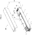
- FIG. 2 is an exploded perspective view of power supply device 100 shown in FIG. 1 with lid case 11 removed.
- FIG. 3 is an exploded perspective of inner assembly 20 shown in FIG. 2 removed from open case 12.
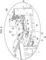
- FIG. 4 is an enlarged perspective view of output unit 22 shown in FIG. 3 .
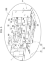
- FIG. 5 is an enlarged perspective view of output unit 22 shown in FIG. 4 viewed from an obliquely downward.
- Power supply device 100 shown in these drawings includes housing 10 and inner assembly 20. Housing 10 accommodates contents therein. Housing 10 shown in FIG. 1 has a box shape and has a storage space accommodating inner assembly 20 therein. In the example shown in FIG. 2 , housing 10 is divided into two pieces, lid case 11 and open case 12. Open case 12 has an opening surface. Lid case 11 closes the opening surface of open case 12. Housing 10 is made of metal, resin, or the like.
- Inner assembly 20 includes battery block 21 including one or more battery cells 1, and output unit 22 including external output terminal 23.
- battery block 21 includes cylindrical secondary battery cells in a battery holder such that the battery cells are aligned vertically. Battery cells 1 are connected in parallel and series to one another.
- output unit 22 includes unit case 24, circuit board 30, external output terminal 23, and guide piece 26.
- Unit case 24 constitutes a part of housing 10 that accommodates the content therein, and retains circuit board 30 and external output terminal 23.
- Unit case 24 is made of an insulative material, such as resin.
- Circuit board 30 Electronic circuits are mounted on circuit board 30.
- the electronic circuits may be a voltage detection circuit that detects the total potential of or the potential at the middle of a battery assembly in which battery cells 1 are connected in series or parallel to one another, a control circuit that controls charging and discharging, a safety circuit, and the like.
- Circuit board 30 has a rectangular shape.
- circuit board 30 includes two boards, first board 31 and second board 32.
- First board 31 and second board 32 are coupled with a space provided by spacer 33 in between.
- First board 31 and second board 32 are electrically connected to each other via board connector 34.
- square C-shaped conductive spacers 40 are fixed on a lower surface of second board 32.
- First board 31 and second board 32 may preferably be made of a material having flexibility, for example, a resin such as glass epoxy.
- Each of square C-shaped conductive spacers 40 has a square U cross-sectional shape. As illustrated in the cross-sectional view of FIG. 7 , square C-shaped conductive spacers 40 are screw-fitted and electrically connected to circular terminals 50 with screws 45. Thus, each square U-shaped conductive spacer 40 has spacer threaded hole 41 for being screw-fitted with screw 45 in an upper surface of the square U shape.
- FIG. 6 has a configuration in which square U-shaped conductive spacers 40 are screw-fitted to unit case 24 with screws 45 from the reverse surface side (the upper surface side shown in FIG. 6 ) of second board 32. For this reason, large board through-holes 35 through which screw head 46 of screw 45 can inserted are formed in the reverse surface side of the locations of second board 32 at which square U-shaped conductive spacers 40 are provided. As a result, second board 32 on which square U-shaped conductive spacers 40 have been previously soldered is placed on unit case 24 on which square nut 38 and circular terminal 50 are previously set, and screw 45 is fastened together with circular terminal 50 from the reverse side of square U-shaped conductive spacer 40 through board through-hole 35.
- This configuration allows square U-shaped conductive spacers 40 which have been soldered on the obverse surface side of second board 32 to be screw-fitted to circular terminals 50 even from the reverse surface side of second board 32.
- circular terminal 50 and second board 32 are fixed to unit case 24 simultaneously because of the configuration in which circular terminal 50 is fastened together with square U-shaped conductive spacers 40.
- circular terminal 50 is screw-fitted from the reverse surface side of second board 32.
- This configuration causes circular terminal 50 to be hidden by second board 32 and prevents circular terminal 50 from being seen. Therefore, even if circular terminal 50 is misaligned, circular terminal 50 is not recognized visually.
- External output terminal 23 is a terminal configured to output to outside the output voltage of battery cells 1 that are connected in series or parallel to one another.
- the total output of battery block 21 is connected to external output terminal 23 via harness 60.
- circular terminals 50 and harness 60 are disposed at the reverse side of circuit board 30. Harness 60 is connected to the output of battery block 21. Circular terminals 50 are electrically connected to circuit board 30.
- First board 31 has first main surface 31a, second main surface 31b opposite of first main surface 31a, and side surface 31c connected to first main surface 31a and second main surface 31b.
- the upper surface of first board 31 is first main surface 31a
- the lower surface of first board 31 is second main surface 31b.
- First Board 31 includes board-side connector 39 on first main surface 31a. Board-side connector 39 is connected to the other end of lead wire 62. As illustrated in FIG. 2 , first board 31 is accommodated in open case 12 such that first main surface 31a faces the opening surface of open case 12.
- First board 31 and second board 32 are connected with lead wire 62, as illustrated in FIG. 5 .
- Lead wire 62 is drawn out from second main surface 31b of first board 31 to first main surface 31a via side surface 31c of first board 31.
- the tip end of lead wire 62 is connected to board-side connector 39.
- lead-side connector 63 is provided at the tip end of lead wire 62.
- Lead wire 62 is made of material having flexibility.
- Circuit board 30 has cut-out 70 formed in a portion of an edge thereof, as illustrated in FIGS. 4 and 5 .
- Lead wire 62 is drawn out from second main surface 31b of circuit board 30 through cut-out 70 to first main surface 31a.
- Cut-out 70 provided in side surface 31c of circuit board 30 (board 31) constitutes opening 131a in first main surface 31a of board 31 and opening 131b in second main surface 31b.
- Lead wire 62 extends from first tip end 62a, connected to board-side connector 39 to second tip end 62b through openings 131a and 131b of cut-out 70 in side surface 31c of board 31.
- Lead wire 62 is provided with pull-out blocker 65 disposed at intermediate position 62c on lead wire 62 between first tip end 62a and second tip end 62b. Pull-out blocker 65 protrudes to be prevented from passing through cut-out 70. Lead wire 62 is configured not to be pulled out greater than or equal to a predetermined length to first main surface 31a by pull-out blocker 65. In other words, lead wire 62 is configured to have pull-out blocker 65 prevent portion 162 of lead wire 62 extending from first tip end 62a to cut-out 70 of board 31 from having a length exceeding a predetermined length. Such a configuration avoids the pinching of lead wire 62 when lid case 11 closes the opening of open case 12.
- lead wire 962 is designed to be somewhat longer to provide a sufficient stroke in inserting lead-side connector 963 of lead wire 962 into board-side connector 939 and to make the work easier. Consequently, lead wire 962 is provided with a degree of freedom so that lead wire 962 is movable easily within open case 912. For this reason, lead wire 962 may be pinched erroneously as illustrated in FIG. 12 when lid case 911 closes.
- power supply device 100 has a lead holding structure that restrains lead wire 62 so as not to move freely.
- cut-out 70 is formed in a portion of the edge of circuit board 30 to restrict the position of lead wire 62 in a direction parallel to main surfaces 31a and 31b of board 31.
- the position of lead wire 62 that is in a direction away from main surface 31a of board 31 is determined by pull-out blocker 65 provided on lead wire 62.
- pull-out blocker 65 provided on lead wire 62.
- pull-out blocker 65 is provided at a position that is at a middle of lead wire 62 and that results in a length that ensures a minimum stroke necessary to easily insert and remove lead-side connector 63 at the tip end of lead wire 62 into and from board-side connector 39.
- This configuration controls the length and position of an excess portion of lead wire 62. That is, while maintaining the workability so as not to prevent the work of inserting lead-side connector 63, provided at the tip end of lead wire 62, into board-side connector 39, by providing a sufficient length of the excess portion of lead wire 62, lead wire 62 is restrained by pull-out blocker 65 so as not to be pulled out beyond a predetermined length.
- Pull-out blocker 65 is disposed at a middle of lead wire 62 from cut-out 70 of board 31 to second tip end 62b of lead wire 62. Pull-out blocker 65 is configured to contacts second main surface 31b of board 31 when the length of portion 162 of lead wire 62 from cut-out 70 of board 31 to first tip end 62a is a predetermined length.
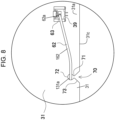
- cut-out 70 preferably includes neck portion 71 with an opening width locally decreasing.
- the opening width of neck portion 71 is designed so as to be equal to or less than the diameter of the cross section of lead wire 62.
- Cut-out 70 further includes circular retaining portion 72 with a circular shape connected continuously to neck portion 71. This configuration allows lead wire 62 to be hardly taken out of cut-out 70 after lead wire 62 is press-fitted into cut-out 70 and pushed into circular retaining portion 72 beyond neck portion 71.
- lead wire 62 is made of material having flexibility or first board 31 is made of a material having flexibility, lead wire 62 may be press-fitted easily beyond neck portion 71.
- cut-out 70 includes circular retaining portion 72 larger than the diameter of the cross section of lead wire 62, and wider portion 73 that communicates with circular retaining portion 72 via neck portion 71 and flares to an outside of the circuit board.
- This configuration allows lead wire 62 to be guided from wider portion 73 into circular retaining portion 72 easily, and on the other hand, neck portion 71 prevents lead wire 62 retained by circular retaining portion 72 beyond neck portion 71 from being taken out from cut-out 70.
- Pull-out blocker 65 may have a configuration preventing lead wire 62 from being pulled out greater than or equal to a predetermined length, as appropriate.
- pull-out blocker 65 has a tab shape attached at a limit length position at which pull-out is permitted. This tab shape protrudes from the side surface of lead wire 62.
- the tab shape protruding in one direction from the outer circumference of lead wire 62 is formed by affixing a rectangular-shaped sticker to lead wire 62 so as to pinch lead wire 62.
- lead wire 62 including the tab shape When lead wire 62 including the tab shape is pulled out toward first main surface 31a, the tab shape contacts second main surface 31b of first board 31 when lead wire 62 is pulled out to some degree, thereby restricting lead wire 62 from being pulled out further.
- lead wire 62 may be pulled out by bringing the direction in which the tab shape protrudes in agreement with the neck portion 71 of cut-out 70.
- a power supply device has a configuration of stopper 65B in which the wire diameter of lead wire 62 locally increases.
- stopper 65B having a wire diameter of lead wire 62 locally increasing contacts second main surface 31b of circuit board 30 when lead wire 62 is pulled out greater than or equal to a predetermined length, thereby preventing lead wire 62 from being pulled out further. Therefore, it is possible to avoid such an incident that the length of a portion of lead wire 62 that is pulled out becomes longer than is necessary, causing pinching or the like.
- this configuration allows pull-out blocker 65 to function irrespective of the rotational direction of lead wire 62.
- Stopper 65B may be implemented by a tube made of rubber, for example.
- a tape may be wrapped around a middle of lead wire 62 to locally increase the wire diameter of lead wire 62 so as not to pass through circular retaining portion 72 of cut-out 70.
- This configuration easily form stopper 65B with the wire diameter of lead wire 62 locally increasing at a desired position of lead wire 62.
- a power supply device and a lead holding structure according to the present disclosure may be suitably used for power sources of portable type electrical appliances, such as electric cleaners and electric power tools.
- the power supply device and the lead holding structure according to the present disclosure may also be appropriately used for applications such as power supply devices for mobile bodies, such as power assisted bicycles and electric carts, and applications in which a lead wire is pulled out to make electrical connection in various types of electrical appliance.
Landscapes
- Chemical & Material Sciences (AREA)
- Chemical Kinetics & Catalysis (AREA)
- Electrochemistry (AREA)
- General Chemical & Material Sciences (AREA)
- Engineering & Computer Science (AREA)
- Human Computer Interaction (AREA)
- Microelectronics & Electronic Packaging (AREA)
- Insertion, Bundling And Securing Of Wires For Electric Apparatuses (AREA)
- Battery Mounting, Suspending (AREA)
Abstract
Description
- The present disclosure relates to a power supply device and a lead holding structure.
- Power supply devices including battery cells connected in series or parallel to one another are used as power sources for portable electric appliances, such as electric cleaners and electric power tools, or in stationary-type electricity storage applications, such as backup power sources for servers or power supply devices for home use, office use, and factory use, or further drive power sources for power assisted bicycles, or drive power sources for vehicles, such as electric scooters, electric carts, hybrid electric vehicles, and battery electric vehicles (for example, PTL 1).
- In such a power supply device, a battery block including battery cells and a circuit board are accommodated in a housing. The housing has a separate structure in which an open case with an opening at its top is closed by a lid case. A lead wire is pulled out from an electric system, such as the battery block.
-
FIG. 11 is an exploded perspective view of a power supply device according to a comparative example for illustratinglead wire 962 inserted into board-side connector 939.Lead wire 962 is configured to be inserted into board-side connector 939 provided oncircuit board 930 while being pulled out from a side surface ofcircuit board 930.Lid case 911 closesopen case 912. - PTL 1:
Japanese Patent Unexamined Publication No. H10-64345 -
FIG. 12 is an exploded perspective view of the power supply device shown inFIG. 11 for illustrating the lead wire pinched when closing the lid. Whenlid case 911 closes,lead wire 962 may be often pinched withlid case 911. The length oflead wire 962 is designed to be sufficiently long with some extra margin, taking into consideration the ease of work when connecting lead-side connector 963 oflead wire 962 to board-side connector 939. Consequently,lead wire 962 with an excess length is likely to wobble easily, increasing the risk of causinglead wire 962 to be placed on the edge ofopen case 912 and to be pinched whenlid case 911 closes. - As a countermeasure for this problem, the lead may be tied wire with a cable tie and secure the lead wire inside the case to prevent unintended wobbling of the lead wire. However, this structure requires the space for placing the cable tie, and necessitates the work of screw-fitting for securing the cable tie onto the case, increasing man-hours.
- On the other hand, when the length of lead wire short so as to avoid pinching of the lead wire, the amount of stroke of the board-side connector inserted into the circuit board is reduced, hardly performing the work.
- Thus, ensuring the workability in connecting the board-side connector of the lead wire and avoiding pinching of the lead wire are conflicting problems in relation to the length of the lead wire, and it has been difficult to solve both problems.
- A power supply device according to an aspect of the present disclosure includes a battery cell, a circuit board including a board-side connector, a lead wire connected to the board-side connector, an open case accommodating the battery cell, the lead wire, and the circuit board therein, a lid case closing an opening surface of the open case, and a pull-out blocker disposed at the lead wire. The circuit board has a first main surface including the board-side connector, a second main surface opposite to the first main surface, and a side surface connected to the first main surface and the second main surface. The side surface of the circuit board has a cut-out therein forming openings in the first main surface and the second main surface. The lead wire has a first tip end and a second tip end, and extends from the first tip end to the second tip end through the openings of the cut-out in the side surface of the circuit board. The first tip end is connected to the board-side connector. The first main surface of the circuit board faces the opening surface of the open case. The pull-out blocker is disposed at an intermediate position of the lead wire between the first tip end and the second tip end of the lead wire. The pull-out blocker protrudes from the lead wire to be prevented from passing through the cut-out. The pull-out blocker is configured to prevent a portion of the lead wire extending from the first tip end to the cut-out of the circuit board from having a length greater than or equal to a predetermined length.
- A lead holding structure in accordance with another aspect of the present disclosure includes a circuit board including a board-side connector, a lead wire connected to the board-side connector, a lid case closing an opening surface of an open case, and a pull-out blocker disposed at the lead wire. The circuit board has a first main surface including the board-side connector, a second main surface opposite to the first main surface, and a side surface connected to the first main surface and the second main surface. The side surface of the circuit board has a cut-out therein forming openings in the first main surface and the second main surface. The lead wire has a first tip end and a second tip end, and extends from the first tip end to the second tip end through the openings of the cut-out in the side surface of the circuit board. The first main surface of the circuit board faces the opening surface of the housing. The pull-out blocker is disposed at an intermediate position of the lead wire between the first tip end and the second tip end of the lead wire. The pull-out blocker protrudes from the lead wire to be prevented from passing through the cut-out. The pull-out blocker is configured to prevent a portion of the lead wire extending from the first tip end to the cut-out of the circuit board from having a length greater than or equal to a predetermined length.
- The power supply device and the lead holding structure according to aspects of the present invention controls the length and position of an excess portion of the lead wire by defining the position of the lead wire in a direction away from the main surface of the circuit board with the pull-out blocker while restricting the position of the lead wire in a direction parallel to the main surface with the cut-out.
-
-
FIG. 1 is a perspective view of a power supply device according to an exemplary embodiment. -
FIG. 2 is an exploded perspective view of the power supply device shown inFIG. 1 with a lid case removed. -
FIG. 3 is an exploded perspective view of the power supply device shown inFIG. 2 for illustrating that an inner assembly thereof is removed from an open case. -
FIG. 4 is an enlarged perspective view of the power supply device shown inFIG. 3 for illustrating an output unit removed. -
FIG. 5 is an enlarged perspective view of the output unit shown inFIG. 4 viewed from an obliquely downward. -
FIG. 6 is an exploded perspective view of the output unit shown inFIG. 4 with a circuit board removed. -
FIG. 7 is a cross-sectional perspective view of the power supply device along line VII-VII shown inFIG. 1 . -
FIG. 8 is an enlarged plan view of a cut-out in a circuit board of the power supply device. -
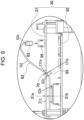
FIG. 9 is a side view illustrating a lead wire shown inFIG. 4 connected to a board-side connector. -
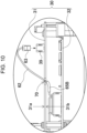
FIG. 10 is an enlarged view of a pull-out blocker according to a modified example. -
FIG. 11 is an exploded perspective view of a power supply device according to a comparative example for illustrating a lead wire inserted into a board-side connector. -
FIG. 12 is an exploded perspective view of the power supply device shown inFIG. 11 for illustrating the lead wire pinched when the lid closes. - Aspects of the present disclosure may be regarded as the following configurations and features.
- In a power supply device according to another aspect of the present disclosure, in an above-described aspect, the cut-out includes a neck portion with an opening width locally decreasing.
- The opening width of the neck portion is equal to or less than a diameter of a cross section of the lead wire.
- In a power supply device according to still another aspect of the present disclosure, in any one of the foregoing aspects, the cut-out further includes a circular retaining portion larger than the diameter of the cross section of the lead wire, and a wider portion communicating with the circular retaining portion via the neck portion, the wider portion flaring to an outside of the circuit board. This configuration allows the lead wire to be guided from the wider portion into the circular retaining portion easily, and on the other hand, avoids disengagement of the lead wire that is retained by the circular retaining portion beyond the neck portion from the cut-out due to the neck portion.
- In a power supply device according to still another aspect of the present disclosure, in any one of the foregoing aspects, the circuit board is made of a material having flexibility. This configuration allows the lead wire to be press-fitted into the cut-out easily.
- In a power supply device according to still another aspect of the present disclosure, in any one of the foregoing aspects, the pull-out blocker has a tab shape attached at a position that is at a middle of the lead wire and that is at a limit length at which pull-out is permitted. The tab shape protrudes from a side surface of the lead wire. In this configuration, even when it is attempted to pull out the lead wire from the cut-out of the circuit board, the tab shape protruding from the lead wire contacts the second main surface of the circuit board when the lead wire is pulled out longer than or equal to a predetermined length, thereby preventing the lead wire from being pulled out further. Thus, the length of the pulled-out portion of the lead wire is prevented from being longer than necessary.
- In a power supply device according to still another aspect of the present disclosure, in any one of the foregoing aspects, the pull-out blocker is a stopper with a wire diameter of the lead wire locally increasing at a middle of the lead wire which a limit length at which pull-out is permitted. In this configuration, even when it is attempted to pull out the lead wire from the cut-out of the circuit board, the stopper with the large wire diameter of the lead wire contacts the second main surface of the circuit board when the lead wire is pulled out longer than or equal to a predetermined length, thereby preventing the lead wire from being pulled out further. Therefore, the length of the pulled-out portion of the lead wire is prevented from being longer than necessary.
- In a power supply device according to still another aspect of the present disclosure, in any one of the foregoing aspects, the stopper is a tape wound around a middle of the lead wire. This configuration provides the stopper with the wire diameter of the lead wire locally increasing at a desired position on the lead wire.
- Exemplary embodiments of the present disclosure will be described below with reference to the drawings. The following embodiments are merely examples for embodying the technical ideas of the present invention, and the present invention is not limited to the following exemplary embodiments. In addition, the present description is in no way provided for limiting the members shown in the claims to the members illustrated in the exemplary embodiments. Moreover, the dimensions, materials, shapes, relative arrangements, and the like of parts and elements described in the following exemplary embodiments are merely illustrative examples, and should not be construed to limit the scope of the invention, unless specifically stated otherwise. Furthermore, the sizes of some elements, their positional relationships, and so forth shown in the drawings may be exaggerated for clarity in illustration. In the following description, like names and symbols refer to same or similar elements, and detailed description thereof will not be given as appropriate. Furthermore, each of the elements that constitute the present disclosure may be embodied by an embodiment in which one member serves as a plurality of elements so that the plurality of elements are composed of the same member, or conversely, may be achieved in such an embodiment in which the function of one member is shared among a plurality of members.
- The power supply device of the present disclosure may be utilized as a power source for portable electric appliances, such as electric cleaners and electric power tools, or as a power supply device in stationary-type electricity storage applications, such as backup power sources for servers, home use, office use, and factory use power supply devices, or further, drive power sources for power assisted bicycles, or drive power sources for vehicles, such as electric scooters, electric carts, hybrid electric vehicles, and battery electric vehicles. Hereinafter, a power supply device used as a backup power source for servers or the like is described as one exemplary embodiment of the present disclosure.
-
Power supply device 100 according to an exemplary embodiment of the present disclosure is shown inFIGS. 1-5 .FIG. 1 is a perspective view ofpower supply device 100 according to the embodiment.FIG. 2 is an exploded perspective view ofpower supply device 100 shown inFIG. 1 withlid case 11 removed.FIG. 3 is an exploded perspective ofinner assembly 20 shown inFIG. 2 removed fromopen case 12.FIG. 4 is an enlarged perspective view ofoutput unit 22 shown inFIG. 3 .FIG. 5 is an enlarged perspective view ofoutput unit 22 shown inFIG. 4 viewed from an obliquely downward.Power supply device 100 shown in these drawings includeshousing 10 andinner assembly 20.Housing 10 accommodates contents therein.Housing 10 shown inFIG. 1 has a box shape and has a storage space accommodatinginner assembly 20 therein. In the example shown inFIG. 2 ,housing 10 is divided into two pieces,lid case 11 andopen case 12.Open case 12 has an opening surface.Lid case 11 closes the opening surface ofopen case 12.Housing 10 is made of metal, resin, or the like. -
Inner assembly 20 includesbattery block 21 including one ormore battery cells 1, andoutput unit 22 includingexternal output terminal 23. In the example ofFIG. 3 ,battery block 21 includes cylindrical secondary battery cells in a battery holder such that the battery cells are aligned vertically.Battery cells 1 are connected in parallel and series to one another. - As illustrated in
FIGS. 4 and5 ,output unit 22 includesunit case 24,circuit board 30,external output terminal 23, and guidepiece 26.Unit case 24 constitutes a part ofhousing 10 that accommodates the content therein, and retainscircuit board 30 andexternal output terminal 23.Unit case 24 is made of an insulative material, such as resin. - Electronic circuits are mounted on
circuit board 30. The electronic circuits may be a voltage detection circuit that detects the total potential of or the potential at the middle of a battery assembly in whichbattery cells 1 are connected in series or parallel to one another, a control circuit that controls charging and discharging, a safety circuit, and the like.Circuit board 30 has a rectangular shape. - In the example of
FIG. 6 ,circuit board 30 includes two boards,first board 31 andsecond board 32.First board 31 andsecond board 32 are coupled with a space provided byspacer 33 in between.First board 31 andsecond board 32 are electrically connected to each other viaboard connector 34. In addition, square C-shapedconductive spacers 40 are fixed on a lower surface ofsecond board 32.First board 31 andsecond board 32 may preferably be made of a material having flexibility, for example, a resin such as glass epoxy. - Each of square C-shaped
conductive spacers 40 has a square U cross-sectional shape. As illustrated in the cross-sectional view ofFIG. 7 , square C-shapedconductive spacers 40 are screw-fitted and electrically connected tocircular terminals 50 withscrews 45. Thus, each square U-shapedconductive spacer 40 has spacer threadedhole 41 for being screw-fitted withscrew 45 in an upper surface of the square U shape. - The example of
FIG. 6 has a configuration in which square U-shapedconductive spacers 40 are screw-fitted tounit case 24 withscrews 45 from the reverse surface side (the upper surface side shown inFIG. 6 ) ofsecond board 32. For this reason, large board through-holes 35 through which screwhead 46 ofscrew 45 can inserted are formed in the reverse surface side of the locations ofsecond board 32 at which square U-shapedconductive spacers 40 are provided. As a result,second board 32 on which square U-shapedconductive spacers 40 have been previously soldered is placed onunit case 24 on whichsquare nut 38 andcircular terminal 50 are previously set, and screw 45 is fastened together with circular terminal 50 from the reverse side of square U-shapedconductive spacer 40 through board through-hole 35. This configuration allows square U-shapedconductive spacers 40 which have been soldered on the obverse surface side ofsecond board 32 to be screw-fitted tocircular terminals 50 even from the reverse surface side ofsecond board 32. Particularly in the configuration ofFIG. 7 ,circular terminal 50 andsecond board 32 are fixed tounit case 24 simultaneously because of the configuration in whichcircular terminal 50 is fastened together with square U-shapedconductive spacers 40. As illustrated inFIG. 6 ,circular terminal 50 is screw-fitted from the reverse surface side ofsecond board 32. This configuration causescircular terminal 50 to be hidden bysecond board 32 and prevents circular terminal 50 from being seen. Therefore, even ifcircular terminal 50 is misaligned,circular terminal 50 is not recognized visually. Wherecircular terminal 50 needs to be held reliably in a positioning posture, the above-described configuration allows terminal threaded hole 53 of circular terminal 50 to be continuously centered withsquare nut 38 retained onnut holding wall 25, performing the assembling work smoothly. Whilesecond board 32 is screw-fitted tounit case 24,first board 31 is secured to the reverse surface side ofsecond board 32. -
External output terminal 23 is a terminal configured to output to outside the output voltage ofbattery cells 1 that are connected in series or parallel to one another. The total output ofbattery block 21 is connected toexternal output terminal 23 viaharness 60. - As illustrated in
FIG. 6 ,circular terminals 50 andharness 60 are disposed at the reverse side ofcircuit board 30.Harness 60 is connected to the output ofbattery block 21.Circular terminals 50 are electrically connected tocircuit board 30. -
First board 31 has firstmain surface 31a, secondmain surface 31b opposite of firstmain surface 31a, andside surface 31c connected to firstmain surface 31a and secondmain surface 31b. InFIGS. 4 and5 , the upper surface offirst board 31 is firstmain surface 31a, and the lower surface offirst board 31 is secondmain surface 31b.First Board 31 includes board-side connector 39 on firstmain surface 31a. Board-side connector 39 is connected to the other end oflead wire 62. As illustrated inFIG. 2 ,first board 31 is accommodated inopen case 12 such that firstmain surface 31a faces the opening surface ofopen case 12. -
First board 31 andsecond board 32 are connected withlead wire 62, as illustrated inFIG. 5 .Lead wire 62 is drawn out from secondmain surface 31b offirst board 31 to firstmain surface 31a viaside surface 31c offirst board 31. The tip end oflead wire 62 is connected to board-side connector 39. For this reason, lead-side connector 63 is provided at the tip end oflead wire 62.Lead wire 62 is made of material having flexibility. -
Circuit board 30 has cut-out 70 formed in a portion of an edge thereof, as illustrated inFIGS. 4 and5 .Lead wire 62 is drawn out from secondmain surface 31b ofcircuit board 30 through cut-out 70 to firstmain surface 31a. Cut-out 70 provided inside surface 31c of circuit board 30 (board 31) constitutesopening 131a in firstmain surface 31a ofboard 31 andopening 131b in secondmain surface 31b.Lead wire 62 extends fromfirst tip end 62a, connected to board-side connector 39 tosecond tip end 62b throughopenings side surface 31c ofboard 31.Lead wire 62 is provided with pull-out blocker 65 disposed atintermediate position 62c onlead wire 62 betweenfirst tip end 62a andsecond tip end 62b. Pull-out blocker 65 protrudes to be prevented from passing through cut-out 70.Lead wire 62 is configured not to be pulled out greater than or equal to a predetermined length to firstmain surface 31a by pull-out blocker 65. In other words,lead wire 62 is configured to have pull-out blocker 65 preventportion 162 oflead wire 62 extending fromfirst tip end 62a to cut-out 70 ofboard 31 from having a length exceeding a predetermined length. Such a configuration avoids the pinching oflead wire 62 whenlid case 11 closes the opening ofopen case 12. - As illustrated in
FIG. 11 , in the configuration in which leadwire 962 is connected to board-side connector 939 ofcircuit board 930,lead wire 962 is designed to be somewhat longer to provide a sufficient stroke in inserting lead-side connector 963 oflead wire 962 into board-side connector 939 and to make the work easier. Consequently,lead wire 962 is provided with a degree of freedom so thatlead wire 962 is movable easily withinopen case 912. For this reason,lead wire 962 may be pinched erroneously as illustrated inFIG. 12 whenlid case 911 closes. - In view of the problem,
power supply device 100 according to the present embodiment has a lead holding structure that restrainslead wire 62 so as not to move freely. Specifically, as illustrated inFIGS. 4 ,5 , and8 , cut-out 70 is formed in a portion of the edge ofcircuit board 30 to restrict the position oflead wire 62 in a direction parallel tomain surfaces board 31. Furthermore, the position oflead wire 62 that is in a direction away frommain surface 31a ofboard 31 is determined by pull-out blocker 65 provided onlead wire 62. Specifically, as illustrated inFIG. 9 , pull-out blocker 65 is provided at a position that is at a middle oflead wire 62 and that results in a length that ensures a minimum stroke necessary to easily insert and remove lead-side connector 63 at the tip end oflead wire 62 into and from board-side connector 39. This configuration controls the length and position of an excess portion oflead wire 62. That is, while maintaining the workability so as not to prevent the work of inserting lead-side connector 63, provided at the tip end oflead wire 62, into board-side connector 39, by providing a sufficient length of the excess portion oflead wire 62,lead wire 62 is restrained by pull-out blocker 65 so as not to be pulled out beyond a predetermined length. This configuration avoids pinching oflead wire 62 bylid case 11 whenlid case 11 closes the opening ofopen case 12. Pull-out blocker 65 is disposed at a middle oflead wire 62 from cut-out 70 ofboard 31 tosecond tip end 62b oflead wire 62. Pull-out blocker 65 is configured to contacts secondmain surface 31b ofboard 31 when the length ofportion 162 oflead wire 62 from cut-out 70 ofboard 31 tofirst tip end 62a is a predetermined length. - As illustrated in the enlarged view of
FIG. 8 , cut-out 70 preferably includesneck portion 71 with an opening width locally decreasing. The opening width ofneck portion 71 is designed so as to be equal to or less than the diameter of the cross section oflead wire 62. Cut-out 70 further includes circular retainingportion 72 with a circular shape connected continuously toneck portion 71. This configuration allowslead wire 62 to be hardly taken out of cut-out 70 afterlead wire 62 is press-fitted into cut-out 70 and pushed into circular retainingportion 72 beyondneck portion 71. Particular in the case that leadwire 62 is made of material having flexibility orfirst board 31 is made of a material having flexibility,lead wire 62 may be press-fitted easily beyondneck portion 71. - In the example of
FIG. 8 , cut-out 70 includes circular retainingportion 72 larger than the diameter of the cross section oflead wire 62, andwider portion 73 that communicates with circular retainingportion 72 vianeck portion 71 and flares to an outside of the circuit board. This configuration allowslead wire 62 to be guided fromwider portion 73 into circular retainingportion 72 easily, and on the other hand,neck portion 71 preventslead wire 62 retained by circular retainingportion 72 beyondneck portion 71 from being taken out from cut-out 70. - Pull-
out blocker 65 may have a configuration preventinglead wire 62 from being pulled out greater than or equal to a predetermined length, as appropriate. For example, in the example shown inFIG. 9 , pull-out blocker 65 has a tab shape attached at a limit length position at which pull-out is permitted. This tab shape protrudes from the side surface oflead wire 62. For example, the tab shape protruding in one direction from the outer circumference oflead wire 62 is formed by affixing a rectangular-shaped sticker to leadwire 62 so as to pinchlead wire 62. Whenlead wire 62 including the tab shape is pulled out toward firstmain surface 31a, the tab shape contacts secondmain surface 31b offirst board 31 whenlead wire 62 is pulled out to some degree, thereby restrictinglead wire 62 from being pulled out further. when necessary, such as when it is desired to pull outlead wire 62 particularly,lead wire 62 may be pulled out by bringing the direction in which the tab shape protrudes in agreement with theneck portion 71 of cut-out 70. - As another example of pull-
out blocker 65, a power supply device according to a modified example ofFIG. 10 has a configuration ofstopper 65B in which the wire diameter oflead wire 62 locally increases. In this configuration, even whenlead wire 62 is pulled out from cut-out 70 ofcircuit board 30,stopper 65B having a wire diameter oflead wire 62 locally increasing contacts secondmain surface 31b ofcircuit board 30 whenlead wire 62 is pulled out greater than or equal to a predetermined length, thereby preventinglead wire 62 from being pulled out further. Therefore, it is possible to avoid such an incident that the length of a portion oflead wire 62 that is pulled out becomes longer than is necessary, causing pinching or the like. Moreover, this configuration allows pull-out blocker 65 to function irrespective of the rotational direction oflead wire 62.Stopper 65B may be implemented by a tube made of rubber, for example. - Alternatively, as another pull-
out blocker 65, a tape may be wrapped around a middle oflead wire 62 to locally increase the wire diameter oflead wire 62 so as not to pass through circular retainingportion 72 of cut-out 70. This configuration easily formstopper 65B with the wire diameter oflead wire 62 locally increasing at a desired position oflead wire 62. - A power supply device and a lead holding structure according to the present disclosure may be suitably used for power sources of portable type electrical appliances, such as electric cleaners and electric power tools. The power supply device and the lead holding structure according to the present disclosure may also be appropriately used for applications such as power supply devices for mobile bodies, such as power assisted bicycles and electric carts, and applications in which a lead wire is pulled out to make electrical connection in various types of electrical appliance.
-
- 100
- power supply device
- 1
- battery cell
- 10
- housing
- 11
- lid case
- 12
- open case
- 20
- inner assembly
- 21
- battery block
- 22
- output unit
- 23
- external output terminal
- 24
- unit case
- 25
- nut holding wall
- 26
- guide piece
- 30
- circuit board
- 31
- first board
- 31a
- first main surface
- 32b
- second main surface
- 32
- second board
- 33
- spacer
- 34
- board connector
- 35
- board through-hole
- 38
- square nut
- 39
- board-side connector
- 40
- square U-shaped conductive spacer
- 41
- spacer threaded hole
- 45
- screw
- 46
- screw head
- 50
- circular terminal
- 53
- terminal threaded hole
- 60
- harness
- 62
- lead wire
- 63
- lead-side connector
- 65
- pull-out blocker
- 65B
- stopper
- 70
- cut-out
- 71
- neck portion
- 72
- circular retaining portion
- 73
- wider portion
- 911
- lid case
- 912
- open case
- 930
- circuit board
- 939
- board-side connector
- 962
- lead wire
- 963
- lead-side connector
Claims (10)
- A power supply device comprising:a battery cell;a circuit board having a first main surface, a second main surface opposite to the first main surface, and a side surface connected to the first main surface and the second main surface, the circuit board including a board-side connector on the first main surface, the side surface having a cut-out therein forming openings in the first main surface and the second main surface;a lead wire having a first tip end and a second tip end, and extending from the first tip end to the second tip end through the openings of the cut-out in the side surface of the circuit board, the first tip end being connected to the board-side connector;an open case accommodating the battery cell, the lead wire, and the circuit board therein, the open case having an opening surface that the first main surface of the circuit board faces;a lid case closing the opening surface of the open case; anda pull-out blocker disposed at an intermediate position of the lead wire between the first tip end and the second tip end of the lead wire, wherein:the pull-out blocker protrudes from the lead wire to be prevented from passing through the cut-out; andthe pull-out blocker is configured to prevent a portion of the lead wire extending from the first tip end to the cut-out of the circuit board from having a length greater than or equal to a predetermined length.
- The power supply device according to claim 1, wherein:the cut-out includes a neck portion having an opening width locally decreasing; andthe opening width of the neck portion is equal to or less than a diameter of a cross section of the lead wire.
- The power supply device according to claim 2, wherein the cut-out further includes:a circular retaining portion larger than the diameter of the cross section of the lead wire; anda wider portion communicating with the circular retaining portion via the neck portion, the wider portion flaring to an outside of the circuit board.
- The power supply device according to any one of claims 1 to 3, wherein the circuit board is made of a material having flexibility.
- The power supply device according to any one of claims 1 to 4, wherein:the pull-out blocker is in a tab shape; andthe tab shape protrudes from a side surface of the lead wire.
- The power supply device according to any one of claims 1 to 4, wherein the pull-out blocker is a stopper at which a diameter of the lead wire locally increases.
- The power supply device according to claim 6, wherein the pull-out blocker is made of a tape wound on a middle of the lead wire.
- The power supply device according to any one of claims 1 to 7, wherein the pull-out blocker is disposed between the second tip end and the cut-out of the circuit board.
- The power supply device according to any one of claims 1 to 8, wherein the pull-out blocker is configured to contact the second main surface of the circuit board when the length of the portion of the lead wire from the cut-out of the circuit board to the first tip end of the lead wire is the predetermined length.
- A lead holding structure comprising:a circuit board having a first main surface, a second main surface opposite to the first main surface, and a side surface connected to the first main surface and the second main surface, the circuit board including a board-side connector on the first main surface, the side surface having a cut-out therein forming openings in the first main surface and the second main surface;a lead wire having a first tip end and a second tip end, and extending from the first tip end to the second tip end through the openings of the cut-out in the side surface of the circuit board, the first tip end being connected to the board-side connector;a housing accommodating the lead wire and the circuit board therein, the housing having an opening surface that the first main surface of the circuit board faces; anda pull-out blocker disposed at an intermediate position of the lead wire between the first tip end and the second tip end of the lead wire, wherein:the pull-out blocker protrudes from the lead wire to be prevented from passing through the cut-out; andthe pull-out blocker is configured to prevent a portion of the lead wire extending from the first tip end to the cut-out of the circuit board from having a length greater than or equal to a predetermined length.
Applications Claiming Priority (2)
| Application Number | Priority Date | Filing Date | Title |
|---|---|---|---|
| JP2022044335 | 2022-03-18 | ||
| PCT/JP2023/007205 WO2023176417A1 (en) | 2022-03-18 | 2023-02-28 | Power supply device and lead holding structure |
Publications (2)
| Publication Number | Publication Date |
|---|---|
| EP4496098A1 true EP4496098A1 (en) | 2025-01-22 |
| EP4496098A4 EP4496098A4 (en) | 2026-01-07 |
Family
ID=88023531
Family Applications (1)
| Application Number | Title | Priority Date | Filing Date |
|---|---|---|---|
| EP23770375.6A Pending EP4496098A4 (en) | 2022-03-18 | 2023-02-28 | POWER SUPPLY DEVICE AND CABLE HOLDING STRUCTURE |
Country Status (5)
| Country | Link |
|---|---|
| US (1) | US20250192337A1 (en) |
| EP (1) | EP4496098A4 (en) |
| JP (1) | JPWO2023176417A1 (en) |
| CN (1) | CN118805293A (en) |
| WO (1) | WO2023176417A1 (en) |
Family Cites Families (12)
| Publication number | Priority date | Publication date | Assignee | Title |
|---|---|---|---|---|
| JPS615837Y2 (en) * | 1981-03-30 | 1986-02-21 | ||
| JPS62216158A (en) * | 1986-03-17 | 1987-09-22 | Canon Inc | Electronic apparatus |
| JPH073179U (en) * | 1993-06-08 | 1995-01-17 | ホシデン株式会社 | PCB fixing structure for lead wire |
| JPH1064345A (en) | 1996-08-19 | 1998-03-06 | Ricoh Co Ltd | Wire bundle unit |
| JPH10341086A (en) * | 1997-06-09 | 1998-12-22 | Mitsubishi Electric Corp | Lead clamper |
| JP3493659B2 (en) * | 2000-06-06 | 2004-02-03 | 船井電機株式会社 | Wire processing structure of lead wire |
| JP2002216723A (en) * | 2001-01-19 | 2002-08-02 | Pfu Ltd | Battery unit structure |
| JP2003092820A (en) * | 2001-09-19 | 2003-03-28 | Mitsumi Electric Co Ltd | Cable mounting structure |
| JP2010238776A (en) * | 2009-03-30 | 2010-10-21 | Sharp Corp | Conductor locking structure, display device, and molding method of resin molded product |
| US20120045665A1 (en) * | 2010-08-17 | 2012-02-23 | Samsung Sdi Co., Ltd. | Battery pack |
| EP3312902B1 (en) * | 2015-06-16 | 2020-01-01 | Hitachi Automotive Systems, Ltd. | Assembled battery |
| WO2018168982A1 (en) * | 2017-03-17 | 2018-09-20 | 三洋電機株式会社 | Battery system and busbar used in same battery system |
-
2023
- 2023-02-28 JP JP2024507687A patent/JPWO2023176417A1/ja active Pending
- 2023-02-28 US US18/845,678 patent/US20250192337A1/en active Pending
- 2023-02-28 WO PCT/JP2023/007205 patent/WO2023176417A1/en not_active Ceased
- 2023-02-28 CN CN202380026782.3A patent/CN118805293A/en active Pending
- 2023-02-28 EP EP23770375.6A patent/EP4496098A4/en active Pending
Also Published As
| Publication number | Publication date |
|---|---|
| EP4496098A4 (en) | 2026-01-07 |
| WO2023176417A1 (en) | 2023-09-21 |
| CN118805293A (en) | 2024-10-18 |
| JPWO2023176417A1 (en) | 2023-09-21 |
| US20250192337A1 (en) | 2025-06-12 |
Similar Documents
| Publication | Publication Date | Title |
|---|---|---|
| US20250357609A1 (en) | Centering for a Cell Connector in a Battery Module | |
| US10811821B2 (en) | Connector device | |
| US5364288A (en) | Electrical connecting device | |
| EP2784841A1 (en) | Connector for cell unit, and cell unit provided with same | |
| US10855024B2 (en) | Electrical connector with latches and terminal position assurance projections provided on hinged cover | |
| US20140273628A1 (en) | Right angle header assembly | |
| JP2014036541A (en) | Electric connection box | |
| US11059437B2 (en) | Electronic module | |
| CN104854759A (en) | Connector, contacts used in the connector, housing, housing with wires and method of manufacturing the housing with wires | |
| US20110237129A1 (en) | Holder-mounting structure | |
| US20170222351A1 (en) | Connector and connection structure | |
| US20250192337A1 (en) | Power supply device and lead holding structure | |
| US20140060880A1 (en) | Protector of electric wire for allowing movement of fixation object | |
| JP5347176B2 (en) | Electrical terminals that lead wiring through walls | |
| EP1115191B1 (en) | Connection assembly particularly for the windings of a stator of an electric motor | |
| JP2015042109A (en) | Terminal board | |
| CN114914591A (en) | a battery | |
| CN219575966U (en) | Wire connecting device | |
| US4613192A (en) | Power cord strain relief | |
| CN101887949B (en) | Fixing mechanism and electronic device adopting same | |
| EP4496097A1 (en) | Power supply device and round terminal securing structure | |
| CN216082961U (en) | Testing device | |
| US10056720B2 (en) | Fuse unit | |
| JP7619995B2 (en) | Electronic component units and wire harnesses | |
| CN216957951U (en) | Fuse holder |
Legal Events
| Date | Code | Title | Description |
|---|---|---|---|
| STAA | Information on the status of an ep patent application or granted ep patent |
Free format text: STATUS: THE INTERNATIONAL PUBLICATION HAS BEEN MADE |
|
| PUAI | Public reference made under article 153(3) epc to a published international application that has entered the european phase |
Free format text: ORIGINAL CODE: 0009012 |
|
| STAA | Information on the status of an ep patent application or granted ep patent |
Free format text: STATUS: REQUEST FOR EXAMINATION WAS MADE |
|
| 17P | Request for examination filed |
Effective date: 20241001 |
|
| AK | Designated contracting states |
Kind code of ref document: A1 Designated state(s): AL AT BE BG CH CY CZ DE DK EE ES FI FR GB GR HR HU IE IS IT LI LT LU LV MC ME MK MT NL NO PL PT RO RS SE SI SK SM TR |
|
| DAV | Request for validation of the european patent (deleted) | ||
| DAX | Request for extension of the european patent (deleted) | ||
| A4 | Supplementary search report drawn up and despatched |
Effective date: 20251208 |
|
| RIC1 | Information provided on ipc code assigned before grant |
Ipc: H01M 50/298 20210101AFI20251202BHEP Ipc: H01M 50/213 20210101ALI20251202BHEP Ipc: H01M 50/284 20210101ALI20251202BHEP Ipc: H05K 7/00 20060101ALI20251202BHEP Ipc: H05K 7/14 20060101ALN20251202BHEP |