EP4496097A1 - Power supply device and round terminal securing structure - Google Patents
Power supply device and round terminal securing structure Download PDFInfo
- Publication number
- EP4496097A1 EP4496097A1 EP23770099.2A EP23770099A EP4496097A1 EP 4496097 A1 EP4496097 A1 EP 4496097A1 EP 23770099 A EP23770099 A EP 23770099A EP 4496097 A1 EP4496097 A1 EP 4496097A1
- Authority
- EP
- European Patent Office
- Prior art keywords
- terminal
- round terminal
- power supply
- supply device
- round
- Prior art date
- Legal status (The legal status is an assumption and is not a legal conclusion. Google has not performed a legal analysis and makes no representation as to the accuracy of the status listed.)
- Pending
Links
Images




Classifications
-
- H—ELECTRICITY
- H01—ELECTRIC ELEMENTS
- H01R—ELECTRICALLY-CONDUCTIVE CONNECTIONS; STRUCTURAL ASSOCIATIONS OF A PLURALITY OF MUTUALLY-INSULATED ELECTRICAL CONNECTING ELEMENTS; COUPLING DEVICES; CURRENT COLLECTORS
- H01R4/00—Electrically-conductive connections between two or more conductive members in direct contact, i.e. touching one another; Means for effecting or maintaining such contact; Electrically-conductive connections having two or more spaced connecting locations for conductors and using contact members penetrating insulation
- H01R4/28—Clamped connections, spring connections
- H01R4/30—Clamped connections, spring connections utilising a screw or nut clamping member
- H01R4/305—Clamped connections, spring connections utilising a screw or nut clamping member having means for facilitating engagement of conductive member or for holding it in position
-
- H—ELECTRICITY
- H01—ELECTRIC ELEMENTS
- H01M—PROCESSES OR MEANS, e.g. BATTERIES, FOR THE DIRECT CONVERSION OF CHEMICAL ENERGY INTO ELECTRICAL ENERGY
- H01M10/00—Secondary cells; Manufacture thereof
- H01M10/42—Methods or arrangements for servicing or maintenance of secondary cells or secondary half-cells
- H01M10/425—Structural combination with electronic components, e.g. electronic circuits integrated to the outside of the casing
-
- H—ELECTRICITY
- H01—ELECTRIC ELEMENTS
- H01M—PROCESSES OR MEANS, e.g. BATTERIES, FOR THE DIRECT CONVERSION OF CHEMICAL ENERGY INTO ELECTRICAL ENERGY
- H01M50/00—Constructional details or processes of manufacture of the non-active parts of electrochemical cells other than fuel cells, e.g. hybrid cells
- H01M50/20—Mountings; Secondary casings or frames; Racks, modules or packs; Suspension devices; Shock absorbers; Transport or carrying devices; Holders
- H01M50/204—Racks, modules or packs for multiple batteries or multiple cells
- H01M50/207—Racks, modules or packs for multiple batteries or multiple cells characterised by their shape
- H01M50/209—Racks, modules or packs for multiple batteries or multiple cells characterised by their shape adapted for prismatic or rectangular cells
-
- H—ELECTRICITY
- H01—ELECTRIC ELEMENTS
- H01M—PROCESSES OR MEANS, e.g. BATTERIES, FOR THE DIRECT CONVERSION OF CHEMICAL ENERGY INTO ELECTRICAL ENERGY
- H01M50/00—Constructional details or processes of manufacture of the non-active parts of electrochemical cells other than fuel cells, e.g. hybrid cells
- H01M50/20—Mountings; Secondary casings or frames; Racks, modules or packs; Suspension devices; Shock absorbers; Transport or carrying devices; Holders
- H01M50/284—Mountings; Secondary casings or frames; Racks, modules or packs; Suspension devices; Shock absorbers; Transport or carrying devices; Holders with incorporated circuit boards, e.g. printed circuit boards [PCB]
-
- H—ELECTRICITY
- H01—ELECTRIC ELEMENTS
- H01M—PROCESSES OR MEANS, e.g. BATTERIES, FOR THE DIRECT CONVERSION OF CHEMICAL ENERGY INTO ELECTRICAL ENERGY
- H01M50/00—Constructional details or processes of manufacture of the non-active parts of electrochemical cells other than fuel cells, e.g. hybrid cells
- H01M50/20—Mountings; Secondary casings or frames; Racks, modules or packs; Suspension devices; Shock absorbers; Transport or carrying devices; Holders
- H01M50/298—Mountings; Secondary casings or frames; Racks, modules or packs; Suspension devices; Shock absorbers; Transport or carrying devices; Holders characterised by the wiring of battery packs
-
- H—ELECTRICITY
- H01—ELECTRIC ELEMENTS
- H01M—PROCESSES OR MEANS, e.g. BATTERIES, FOR THE DIRECT CONVERSION OF CHEMICAL ENERGY INTO ELECTRICAL ENERGY
- H01M50/00—Constructional details or processes of manufacture of the non-active parts of electrochemical cells other than fuel cells, e.g. hybrid cells
- H01M50/50—Current conducting connections for cells or batteries
-
- H—ELECTRICITY
- H01—ELECTRIC ELEMENTS
- H01M—PROCESSES OR MEANS, e.g. BATTERIES, FOR THE DIRECT CONVERSION OF CHEMICAL ENERGY INTO ELECTRICAL ENERGY
- H01M50/00—Constructional details or processes of manufacture of the non-active parts of electrochemical cells other than fuel cells, e.g. hybrid cells
- H01M50/50—Current conducting connections for cells or batteries
- H01M50/543—Terminals
- H01M50/547—Terminals characterised by the disposition of the terminals on the cells
- H01M50/55—Terminals characterised by the disposition of the terminals on the cells on the same side of the cell
-
- H—ELECTRICITY
- H01—ELECTRIC ELEMENTS
- H01M—PROCESSES OR MEANS, e.g. BATTERIES, FOR THE DIRECT CONVERSION OF CHEMICAL ENERGY INTO ELECTRICAL ENERGY
- H01M50/00—Constructional details or processes of manufacture of the non-active parts of electrochemical cells other than fuel cells, e.g. hybrid cells
- H01M50/50—Current conducting connections for cells or batteries
- H01M50/543—Terminals
- H01M50/552—Terminals characterised by their shape
- H01M50/553—Terminals adapted for prismatic, pouch or rectangular cells
-
- H—ELECTRICITY
- H01—ELECTRIC ELEMENTS
- H01M—PROCESSES OR MEANS, e.g. BATTERIES, FOR THE DIRECT CONVERSION OF CHEMICAL ENERGY INTO ELECTRICAL ENERGY
- H01M50/00—Constructional details or processes of manufacture of the non-active parts of electrochemical cells other than fuel cells, e.g. hybrid cells
- H01M50/50—Current conducting connections for cells or batteries
- H01M50/543—Terminals
- H01M50/564—Terminals characterised by their manufacturing process
- H01M50/567—Terminals characterised by their manufacturing process by fixing means, e.g. screws, rivets or bolts
-
- H—ELECTRICITY
- H01—ELECTRIC ELEMENTS
- H01R—ELECTRICALLY-CONDUCTIVE CONNECTIONS; STRUCTURAL ASSOCIATIONS OF A PLURALITY OF MUTUALLY-INSULATED ELECTRICAL CONNECTING ELEMENTS; COUPLING DEVICES; CURRENT COLLECTORS
- H01R11/00—Individual connecting elements providing two or more spaced connecting locations for conductive members which are, or may be, thereby interconnected, e.g. end pieces for wires or cables supported by the wire or cable and having means for facilitating electrical connection to some other wire, terminal, or conductive member, blocks of binding posts
- H01R11/11—End pieces or tapping pieces for wires, supported by the wire and for facilitating electrical connection to some other wire, terminal or conductive member
- H01R11/12—End pieces terminating in an eye, hook, or fork
-
- H—ELECTRICITY
- H01—ELECTRIC ELEMENTS
- H01R—ELECTRICALLY-CONDUCTIVE CONNECTIONS; STRUCTURAL ASSOCIATIONS OF A PLURALITY OF MUTUALLY-INSULATED ELECTRICAL CONNECTING ELEMENTS; COUPLING DEVICES; CURRENT COLLECTORS
- H01R4/00—Electrically-conductive connections between two or more conductive members in direct contact, i.e. touching one another; Means for effecting or maintaining such contact; Electrically-conductive connections having two or more spaced connecting locations for conductors and using contact members penetrating insulation
- H01R4/28—Clamped connections, spring connections
- H01R4/30—Clamped connections, spring connections utilising a screw or nut clamping member
- H01R4/34—Conductive members located under head of screw
-
- H—ELECTRICITY
- H01—ELECTRIC ELEMENTS
- H01M—PROCESSES OR MEANS, e.g. BATTERIES, FOR THE DIRECT CONVERSION OF CHEMICAL ENERGY INTO ELECTRICAL ENERGY
- H01M2220/00—Batteries for particular applications
- H01M2220/20—Batteries in motive systems, e.g. vehicle, ship, plane
-
- Y—GENERAL TAGGING OF NEW TECHNOLOGICAL DEVELOPMENTS; GENERAL TAGGING OF CROSS-SECTIONAL TECHNOLOGIES SPANNING OVER SEVERAL SECTIONS OF THE IPC; TECHNICAL SUBJECTS COVERED BY FORMER USPC CROSS-REFERENCE ART COLLECTIONS [XRACs] AND DIGESTS
- Y02—TECHNOLOGIES OR APPLICATIONS FOR MITIGATION OR ADAPTATION AGAINST CLIMATE CHANGE
- Y02E—REDUCTION OF GREENHOUSE GAS [GHG] EMISSIONS, RELATED TO ENERGY GENERATION, TRANSMISSION OR DISTRIBUTION
- Y02E60/00—Enabling technologies; Technologies with a potential or indirect contribution to GHG emissions mitigation
- Y02E60/10—Energy storage using batteries
Definitions
- the present disclosure relates to a power supply device and a round terminal securing structure.
- Power supply devices including battery cells connected in series or parallel to one another have been used, for example, as power supplies for portable electric machinery such as electric cleaners and electric tools, as stationary power supplies for server backup for electricity storage or power supply devices in home use, business facility use, or factory use, or as power sources for driving electric assisted bicycles or power supplies for driving electric scooters, electric carts, or vehicles such as hybrid vehicles or electric vehicles (for example, PTL 1).
- a metal member called a round terminal or a crimp terminal is attached to an end edge of a harness to electrically connect the harness.
- the round terminal typically has an end including a crimp part and is attached to the harness by crimping the crimp part.
- the other end of the round terminal has a terminal screw hole to be fastened together with another terminal such as a busbar. Inside the power supply devices, electrical connections are made using the round terminal.
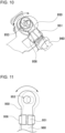
- a repulsive force may be generated depending on the orientation and thickness of harness 960 to which round terminal 950 is attached, as illustrated in FIG. 10 , thereby causing a stress to act in a direction of rotation of round terminal 950 as illustrated by a dashed line in FIG. 11 .
- a round shaped portion of crimp part 951 is held by standing piece 956, and accordingly the area of contact between standing piece 956 and crimp part 951 is small and frictional resistance is low.
- the repulsive force of harness 960 may cause round terminal 950 to rotate, hence displacing round terminal 950 out of the screw hole.
- a power supply device includes: a battery cell; a harness connected to the battery cell; a round terminal connected to the harness; a circuit board electrically connected to the round terminal; a housing accommodating the battery cell, the circuit board, the harness, and the round terminal therein; and a pair of guide pieces holding the round terminal.
- the crimp part includes a flat part including an end portion having a terminal screw hole passing through the flat part in up and down directions, and a crimp part crimped together with an end of the harness so as to be connected to the end of the harness.
- the pair of guide pieces respectively holds edges of the flat part of the round terminal in right and left directions perpendicular to the up and down directions while the round terminal is fixed to the housing with a screw inserted into the terminal screw hole.
- a round terminal securing structure includes a round terminal and a pair of guide pieces holding the round terminal.
- the crimp part includes a flat part including an end portion having a terminal screw hole passing through the flat part in up and down directions, and a crimp part crimped together with an end of a harness so as to be connected to the end of the harness.
- the pair of guide pieces respectively hold edges of the flat part of the round terminal in right and left directions perpendicular to the up and down directions while the round terminal is fixed to a connection object with a screw inserted into the terminal screw hole and fastening the round terminal and the connection object together.
- the guide pieces provided on the right and left sides of the flat part of the round terminal prevent the round terminal from rotating due to the repulsive force of the harness or the like, thus providing stable screwing.
- a power supply device includes: a battery cell; a harness connected to the battery cell; a round terminal connected to the harness; a circuit board electrically connected to the round terminal; a housing accommodating the battery cell, the circuit board, the harness, and the round terminal therein; and a pair of guide pieces holding the round terminal.
- the crimp part includes a flat part including an end portion having a terminal screw hole passing through the flat part in up and down directions, and a crimp part crimped together with an end of the harness so as to be connected to the end of the harness.
- the pair of guide pieces respectively hold edges of the flat part of the round terminal in right and left directions perpendicular to the up and down directions while the round terminal is fixed to the housing with a screw inserted into the terminal screw hole.
- the flat part of the round terminal may have a positioning hole passing through the flat part in the up and down directions, the positioning hole being spaced away from the terminal screw hole.
- the power supply device may further include a positioning pin inserted into the positioning hole while the round terminal is fixed to the housing with the screw passing through the terminal screw hole. In this configuration, the positioning pin is inserted into the positioning hole to position the round terminal, and prevents the rotation of the round terminal due to a repulsive force of the harness.
- the positioning hole may be disposed between the terminal screw hole and the crimp part.
- the positioning hole may have a smaller diameter than the terminal screw hole.
- each of the pair of guide pieces may have an overlapping surface extending continuously from a corresponding one of right and left sides of the round terminal and overlapping the end portion of the round terminal in the up and down directions while holding a corresponding one of the edges of the round terminal in the right and left directions.
- the overlapping surfaces of the guide pieces prevent the round terminal from being lifted due to a repulsive force of the harness.
- the overlapping surfaces of the pair of the guide pieces may have hook shapes.
- a power supply device in any of the above-mentioned aspects may further include a pair of guide pins, each of the guide pins being disposed on a corresponding one of right and left sides of the flat part of the round terminal at a position different from positions of the pair of guide pieces while the round terminal is fixed to the housing with the screw inserted into the terminal screw hole.
- the guide pins prevent undesired rotation of the round terminal.
- a combination of the guide pieces and the guide pins resist a rotational force.
- the guide pins may have circular columnar shapes.
- the guide pins may be formed unitarily with the housing.
- the power supply device in any of the above-mentioned aspects, may further include a rectangular nut aligned with the terminal screw hole of the round terminal, and a nut holder wall holding the rectangular nut to prevent the rectangular nut from rotating.
- the pair of the guide pieces and the nut holder wall may be formed unitarily with the housing.
- the power supply device in any of the above-mentioned embodiments, may further include a U-shaped conductive spacer fixed to the circuit board, the U-shaped conductive spacer having a cross section with a squared U-shape, the U-shaped conductive spacer having a spacer screw hole passing through the U-shaped conductive spacer.
- the circuit board may have a board through-hole provided therein in a region of the circuit board to which the U-shaped conductive spacer is fixed.
- a plurality of constituents may be constituted by an identical member, so that one member functions as a plurality of constituents, or conversely, a function of one member may be shared with and implemented by a plurality of members.
- terms indicating directions such as “up and down directions”, “right and left directions", and “upper surface” indicate relative directions that depend on only the relative positional relationship between constituents of the power supply device, and do not indicate absolute directions such as a vertical direction.
- FIGS. 1-3 Power supply device 100 according to Exemplary Embodiment 1 of the present disclosure is illustrated in FIGS. 1-3 .
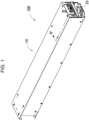
- FIG. 1 is a perspective view of power supply device 100 according to Embodiment 1.
- FIG. 2 is an exploded perspective view of power supply device 100 shown in FIG. 1 .
- FIG. 3 is an exploded perspective view of the device for illustrating a state in which circuit board 30 is removed from output unit 22 shown in FIG. 2 .
- Power supply device 100 illustrated in these drawings includes housing 10 and internal assembly 20. Housing 10 accommodates contents therein. Housing 10 illustrated in FIG. 1 has a box shape and has an accommodating space accommodating internal assembly 20 therein. In an example shown in FIG. 2 , housing 10 is divided into two parts; lid case 11 and opening case 12. Housing 10 is made of, e.g., metal or resin.
- Output unit 22 includes unit case 24, circuit board 30, external output terminal 23, and guide piece 26.
- Unit case 24 constitutes a part of housing 10 configured to accommodate the contents therein and holds circuit board 30 and external output terminal 23.
- Unit case 24 is molded from an insulating material such as resin.
- Circuit board 30 Electronic circuits are mounted on circuit board 30.
- the electronic circuits may be a voltage detection circuit configured to detect the total potential or intermediate potential of a battery assembly including battery cells 1 connected in series or parallel to one another, a control circuit configured to control charging and discharging, and a safety circuit.
- Circuit board 30 has a rectangular shape.
- circuit board 30 includes two boards: first board 31 and second board 32.
- First board 31 and second board 32 are spaced away from each other via spacer 33 and coupled to each other.
- First board 31 and second board 32 are electrically connected to each other via board connector 34.
- U-shaped conductive spacers 40 are fixed to a lower surface of second board 32.
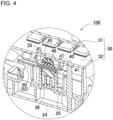
- U-shaped conductive spacer 40 has a cross section with a squared U-shape. As indicated by the cross-sectional view of FIG. 4 , U-shaped conductive spacer 40 is electrically connected to later-described round terminal 50 by screw 45. U-shaped conductive spacer 40 has spacer screw hole 41 in a U-shaped upper surface thereof so that screw 45 is screwed. Spacer screw hole 41 passes through conductive spacer 40 in up and down directions D 1.
- U-shaped conductive spacer 40 is screwed to unit case 24 from a lower surface of second board 32 (the upper side in FIG. 3 ) by screw 45.
- Board through-hole 35 is large enough to allow screw head 46 of screw 45 to be inserted thereinto is opened in the lower surface of a portion of second board 32 to which U-shaped conductive spacer 40 is attached.
- second board 32 to which U-shaped conductive spacer 40 has been previously soldered is placed on unit case 24 in which rectangular nut 38 and round terminal 50 have been previously disposed.
- U-shaped conductive spacer 40 is fastened to round terminal 50 by screw 45 through board through-hole 35 from the lower surface of U-shaped conductive spacer 40.
- U-shaped conductive spacer 40 having been soldered to an upper surface of second board 32 is screwed to round terminal 50 even from the lower surface of second board 32.
- round terminal 50 and U-shaped conductive spacer 40 are fastened together, and therefore, round terminal 50 and second board 32 are fixed to unit case 24 simultaneously.
- round terminal 50 is screwed from the lower surface of second board 32, thereby causing round terminal 50 to be hidden by second board 32 and being invisible. Therefore, even when round terminal 50 is displaced, the displacement is not visually confirmed. Hence, round terminal 50 is required to be surely held to be positioned.
- terminal screw hole 53 of round terminal 50 is surely aligned with threaded hole 138 of rectangular nut 38 held in nut holder wall 25, thereby allowing assembly work to be smoothly performed.
- second board 32 screwed to unit case 24 allows first board 31 to be fixed to the lower surface of second board 32.
- External output terminal 23 is a terminal configured to output, to an external device, an output voltage of battery cells 1 connected in series or parallel to one another. External output terminal 23 is connected to the total output of battery block 21 via harness 60.
- Round terminals 50 and harnesses 60 are disposed on the lower surface of circuit board 30, as illustrated in FIG. 3 and FIG. 5 . Harnesses 60 are connected to the output of battery block 21. Round terminals 50 are electrically connected to circuit board 30.
- Crimp part 51 is configured to be crimped with harness 60 to be connected to harness 60.
- Crimp part 51 includes flat crimp pieces extending to right and left directions before crimping, and the flat crimp pieces are crimped with a stranded wire extending from an end of harness 60 with a plier or another tool so as to sandwich the stranded wire, thereby attaching crimp part 51 to the end of harness 60.
- Flat part 52 is made of a flat plate with a battledore shape. An end of flat part 52 has terminal screw hole 53 therein. Terminal screw hole 53 passes through flat part 52 in up and down directions D1. As illustrated in FIG. 6 , terminal screw hole 53 is a hole into which screw 45 is inserted to fix round terminal 50 to unit case 24 with screw 45. As illustrated in FIG. 7 , unit case 24 includes nut holder walls 25 on a bottom surface to hold rectangular nut 38. Nut holder walls 25 are provided inside unit case 24. Nut holder walls 25 are preferably formed unitarily with unit case 24.
- round terminal 50 is fastened together with a connection object to be electrically connected by screw 45.
- a threaded hole is formed in the connection object.
- round terminal 50 is fastened together with U-shaped conductive spacer 40 fixed to second board 32, as the connection object.
- Output unit 22 includes a pair of guide pieces 26.
- the pair of guide pieces 26 hold right and left sides of flat part 52 of round terminal 50 while round terminal 50 is fixed to unit case 24 with terminal screw hole 53.
- the pair of guide pieces 26 respectively contact edges 152 of flat part 52 of round terminal 50 in right and left directions D2 crossing up and down directions D1 and hold edges 152 while round terminal 50 is fixed to unit case 24 with screw 45 inserted into terminal screw hole 53.
- right and left directions D2 is perpendicular to up and down directions D1.
- guide pieces 26 provided on the right and left sides of flat part 52 of round terminal 50 prevent round terminal 50 from rotating due to a repulsive force of harness 60 or the like, thereby providing stable screwing.
- each of the pair of guide pieces 26 has overlapping surfaces 27 extending continuously from the right and left sides of round terminal 50.
- Each of overlapping surfaces 27 overlaps an end portion of the upper surface of round terminal 50 in up and down directions D1 while holding the right and left sides of round terminal 50.
- respective overlapping surfaces 27 of guide pieces 26 prevent round terminal 50 from being lifted due to a repulsive force of harness 60.
- a round terminal may provide a problem that, when a round shaped portion of a crimp part is secured by a hook or the like, a repulsive force of a harness may cause the round terminal to be lifted or rotate.
- guide pieces 26 have overlap surfaces 27 providing an advantageous effect preventing the round terminal itself from unlikely being lifted and rotating, and are surely screwed.
- Guide pieces 26 are made of elastic material. Guide pieces 26 are preferably formed unitarily with unit case 24. Unit case 24 made of resin easily provides guide pieces 26 with elasticity. Alternatively, guide pieces 26 may be a member independent from the unit case and fixed to an inner surface of the unit case by, e.g., adhesion or engagement.
- Overlapping surface 27 of guide piece 26 preferably has a hook shape.
- inclined surface 28 inclined from an end of each of guide pieces 26 in a direction gradually narrows the opening, round terminal 50 is more easily guided between guide pieces 26.
- the lower ends of inclined surfaces 28 form a narrowest portion at which the gap between inclined surfaces 28 is the narrowest.
- the narrowest portion is configured to be narrower than flat part 52 of round terminal 50.
- flat part 52 of round terminal 50 has positioning hole 54 spaced away from terminal screw hole 53.
- Positioning hole 54 passes through flat part 52 in up and down directions D1.
- Unit case 24 includes positioning pin 29 configured to be inserted into positioning hole 54 so as to position terminal screw hole 53 of round terminal 50 while being fixed. In this configuration, positioning pin 29 is inserted into positioning hole 54 to position round terminal 50 and prevent round terminal 50 from rotating due to a repulsive force of harness 60.
- Positioning hole 54 is formed between terminal screw hole 53 and crimp unit 51. Positioning hole 54 preferably has different diameter from terminal screw hole 53. This configuration allows positioning hole 54 to be more easily visually distinguished from terminal screw hole 53. In the example in FIG. 7 , positioning hole 54 has a smaller diameter than terminal screw hole 53.
- Unit case 24 may further include a pair of guide pins 29B at positions different from the positions of guide pieces 26, as illustrated in FIG. 6 and FIG. 7 .
- guide pins 29B respectively contact the left and right sides of flat part 52 of round terminal 50 to position round terminal 50.
- guide pins 29B in addition to the pair of guide pieces 26 further prevent the rotation of round terminal 50.
- the combination of guide pieces 26 and guide pins 29B can resist the rotation.
- Guide pins 29B are preferably disposed between nut holder wall 25 and each of the pair of guide pieces 26, as illustrated in FIG. 7 . Thus, side surfaces of flat part 52 are guided in a distributed manner.
- Each guide pin 29B has a circular columnar shape.
- Guide pin 29B is formed unitarily with unit case 24.
- Guide pin 29B is preferably has the same shape as positioning pin 29.
- guide pins 29B and positioning pins 29 are collectively provided inside unit case 24.
- a power supply device and a round terminal securing structure according to the present disclosure are suitably used as a power supply for portable electric machinery such as electric cleaners and electric tools. Furthermore, the power supply device and the round terminal securing structure can be appropriately used as power supply devices for mobile units such as electric assisted bicycles and electric carts, and used in electrical connection applications using a round terminal in various types of electrical equipment.
Landscapes
- Chemical & Material Sciences (AREA)
- Chemical Kinetics & Catalysis (AREA)
- Electrochemistry (AREA)
- General Chemical & Material Sciences (AREA)
- Engineering & Computer Science (AREA)
- Manufacturing & Machinery (AREA)
- Microelectronics & Electronic Packaging (AREA)
- Connection Of Batteries Or Terminals (AREA)
- Connections By Means Of Piercing Elements, Nuts, Or Screws (AREA)
Abstract
Description
- The present disclosure relates to a power supply device and a round terminal securing structure.
- Power supply devices including battery cells connected in series or parallel to one another have been used, for example, as power supplies for portable electric machinery such as electric cleaners and electric tools, as stationary power supplies for server backup for electricity storage or power supply devices in home use, business facility use, or factory use, or as power sources for driving electric assisted bicycles or power supplies for driving electric scooters, electric carts, or vehicles such as hybrid vehicles or electric vehicles (for example, PTL 1).
- In such power supply devices, a metal member called a round terminal or a crimp terminal is attached to an end edge of a harness to electrically connect the harness. The round terminal typically has an end including a crimp part and is attached to the harness by crimping the crimp part. The other end of the round terminal has a terminal screw hole to be fastened together with another terminal such as a busbar. Inside the power supply devices, electrical connections are made using the round terminal.
- At a connection at which electrical connections are made using the round terminal, a screw is inserted into the terminal screw hole of the round terminal, and accordingly the screw holes need to be aligned with each other. Therefore, as illustrated in
FIG. 10 , a round terminal securing structure has been proposed, in which both ends ofcrimp part 951 to crimpround terminal 950 toharness 960 are positioned using standingpieces 956, so thatterminal screw hole 953 ofround terminal 950 is positioned at a screw hole (see PTL 1). - PTL 1:
Japanese Patent Laid-Open Publication No. 2014-220932 - A repulsive force may be generated depending on the orientation and thickness of
harness 960 to whichround terminal 950 is attached, as illustrated inFIG. 10 , thereby causing a stress to act in a direction of rotation ofround terminal 950 as illustrated by a dashed line inFIG. 11 . In a configuration illustrated inFIG. 10 , a round shaped portion ofcrimp part 951 is held by standingpiece 956, and accordingly the area of contact between standingpiece 956 andcrimp part 951 is small and frictional resistance is low. As a result, the repulsive force ofharness 960 may causeround terminal 950 to rotate, hence displacing roundterminal 950 out of the screw hole. When the repulsive force ofharness 960 acts in a direction liftinground terminal 950, the configuration illustrated inFIG. 10 does not prevent the action andround terminal 950 may falls out of standingpiece 956. When the round terminal is not positioned, the work of screwing the round terminal is inhibited, which reduces work efficiency. In particular, when the number of battery cells to be used increases to achieve higher output and higher capacity of a power supply device, the harness is accordingly thicker, which results in a decrease in the flexibility of the harness and an increase in the repulsive force of the harness. On the other hand, as the power supply device saves space, a limitation on wiring routing more easily occurs due to the internal layout of the power supply device, and accordingly requiring the harness to be bent for arrangement. As a result, the repulsive force of the harness is more easily generated at the end edge in the round terminal. - A power supply device according to an aspect of the present disclosure includes: a battery cell; a harness connected to the battery cell; a round terminal connected to the harness; a circuit board electrically connected to the round terminal; a housing accommodating the battery cell, the circuit board, the harness, and the round terminal therein; and a pair of guide pieces holding the round terminal. The crimp part includes a flat part including an end portion having a terminal screw hole passing through the flat part in up and down directions, and a crimp part crimped together with an end of the harness so as to be connected to the end of the harness. The pair of guide pieces respectively holds edges of the flat part of the round terminal in right and left directions perpendicular to the up and down directions while the round terminal is fixed to the housing with a screw inserted into the terminal screw hole.
- A round terminal securing structure according to another aspect of the present disclosure includes a round terminal and a pair of guide pieces holding the round terminal. The crimp part includes a flat part including an end portion having a terminal screw hole passing through the flat part in up and down directions, and a crimp part crimped together with an end of a harness so as to be connected to the end of the harness. The pair of guide pieces respectively hold edges of the flat part of the round terminal in right and left directions perpendicular to the up and down directions while the round terminal is fixed to a connection object with a screw inserted into the terminal screw hole and fastening the round terminal and the connection object together.
- In the power supply device and the round terminal securing structure of the aspects of the present disclosure, the guide pieces provided on the right and left sides of the flat part of the round terminal prevent the round terminal from rotating due to the repulsive force of the harness or the like, thus providing stable screwing.
-
-
FIG. 1 is a perspective view of a power supply device according toExemplary Embodiment 1. -
FIG. 2 is an exploded perspective view of the power supply device shown inFIG. 1 . -
FIG. 3 is an exploded perspective view of the power supply device shown inFIG. 2 for illustrating a state in which a circuit board is removed from an output unit of the power supply device. -
FIG. 4 is a cross-sectional perspective view of the power supply device line IV-IV shown inFIG. 1 . -
FIG. 5 is an enlarged plan view of the power supply device shown inFIG. 3 . -
FIG. 6 is an enlarged perspective view of a main part of the power supply device shown inFIG. 5 . -
FIG. 7 is an exploded perspective view of the power supply device shown inFIG. 6 . -
FIG. 8 is a cross-sectional view of the power supply device line VIII-VIII shown inFIG. 6 . -
FIG. 9 is a cross-sectional view of the power supply device line IX-IX shown inFIG. 6 . -
FIG. 10 is a perspective view of a conventional round terminal securing structure. -
FIG. 11 is a perspective view of a power supply device according to a comparative example for illustrating a state in which a round terminal is positioned in the power supply device. - A power supply device according to an aspect of the present disclosure includes: a battery cell; a harness connected to the battery cell; a round terminal connected to the harness; a circuit board electrically connected to the round terminal; a housing accommodating the battery cell, the circuit board, the harness, and the round terminal therein; and a pair of guide pieces holding the round terminal. The crimp part includes a flat part including an end portion having a terminal screw hole passing through the flat part in up and down directions, and a crimp part crimped together with an end of the harness so as to be connected to the end of the harness. The pair of guide pieces respectively hold edges of the flat part of the round terminal in right and left directions perpendicular to the up and down directions while the round terminal is fixed to the housing with a screw inserted into the terminal screw hole.
- In a power supply device according to another aspect of the present disclosure, in the above-described aspect, the flat part of the round terminal may have a positioning hole passing through the flat part in the up and down directions, the positioning hole being spaced away from the terminal screw hole. The power supply device may further include a positioning pin inserted into the positioning hole while the round terminal is fixed to the housing with the screw passing through the terminal screw hole. In this configuration, the positioning pin is inserted into the positioning hole to position the round terminal, and prevents the rotation of the round terminal due to a repulsive force of the harness.
- In a power supply device according to still another aspect of the present disclosure, in any of the above-mentioned aspects, the positioning hole may be disposed between the terminal screw hole and the crimp part.
- In a power supply device according to still another aspect of the present disclosure, in any of the above-mentioned aspects, the positioning hole may have a smaller diameter than the terminal screw hole.
- In a power supply device according to still another aspect of the present disclosure, in any of the above-mentioned aspects, each of the pair of guide pieces may have an overlapping surface extending continuously from a corresponding one of right and left sides of the round terminal and overlapping the end portion of the round terminal in the up and down directions while holding a corresponding one of the edges of the round terminal in the right and left directions. In this configuration, the overlapping surfaces of the guide pieces prevent the round terminal from being lifted due to a repulsive force of the harness.
- In a power supply device according to still another aspect of the present disclosure, in any of the above-mentioned aspects, the overlapping surfaces of the pair of the guide pieces may have hook shapes.
- A power supply device according to still another aspect of the present disclosure, in any of the above-mentioned aspects may further include a pair of guide pins, each of the guide pins being disposed on a corresponding one of right and left sides of the flat part of the round terminal at a position different from positions of the pair of guide pieces while the round terminal is fixed to the housing with the screw inserted into the terminal screw hole. In this configuration, not only the guide pieces but also the guide pins prevent undesired rotation of the round terminal. In particular, even when a repulsive force of the harness is high, a combination of the guide pieces and the guide pins resist a rotational force.
- In a power supply device according to still another aspect of the present disclosure, in any of the above-mentioned aspects, the guide pins may have circular columnar shapes.
- In a power supply device according to still another aspect of the present disclosure, in any of the above-mentioned aspects, the guide pins may be formed unitarily with the housing.
- The power supply device according to still another aspect of the present disclosure, in any of the above-mentioned aspects, may further include a rectangular nut aligned with the terminal screw hole of the round terminal, and a nut holder wall holding the rectangular nut to prevent the rectangular nut from rotating.
- In a power supply device according to still another aspect of the present disclosure, in any of the above-mentioned aspects, the pair of the guide pieces and the nut holder wall may be formed unitarily with the housing.
- The power supply device according to still another aspect of the present disclosure, in any of the above-mentioned embodiments, may further include a U-shaped conductive spacer fixed to the circuit board, the U-shaped conductive spacer having a cross section with a squared U-shape, the U-shaped conductive spacer having a spacer screw hole passing through the U-shaped conductive spacer. The circuit board may have a board through-hole provided therein in a region of the circuit board to which the U-shaped conductive spacer is fixed. In this configuration, even when the round terminal is hidden by the circuit board and is thereby invisible, the work of screwing the round terminal into the circuit board from the back side of the circuit board is surely performed by aligning the terminal screw hole of the round terminal with the spacer screw hole, thereby enhancing reliability.
- An exemplary embodiment of the present disclosure will be described with reference to the drawings. Note that the embodiments described below are presented as examples embodying a technical idea of the present disclosure, and the present invention is not limited to the followings. In addition, the present specification is not definitely presented to limit members described in the claims to corresponding members described in the embodiments. In particular, unless otherwise specified, dimensions, materials, shapes, relative positions, and the likes of constituents described in the embodiments are only presented as explanatory examples, and are not intended to limit the scope of the present invention. Note that sizes, positional relationships, and the likes of members illustrated in the drawings may be exaggerated for clarifying the description. Furthermore, in the following description, the same names and reference numerals indicate identical or similar members, and detailed description of the members will be omitted as appropriate. In addition, concerning constituents of the present disclosure, a plurality of constituents may be constituted by an identical member, so that one member functions as a plurality of constituents, or conversely, a function of one member may be shared with and implemented by a plurality of members. In the embodiments, terms indicating directions such as "up and down directions", "right and left directions", and "upper surface" indicate relative directions that depend on only the relative positional relationship between constituents of the power supply device, and do not indicate absolute directions such as a vertical direction.
- The power supply device according to the present disclosure can be used, for example, as a power supply for portable electric machinery such as electric cleaners and electric tools, as a stationary power supply for server backup for electricity storage or a power supply device in home use, business facility use, or factory use, or as a power source for driving electric assisted bicycles or a power supply for driving electric scooters, electric carts, or vehicles such as hybrid vehicles or electric vehicles. Hereinafter, the power supply device used as a power source for server backup or the like will be described as an embodiment of the present disclosure.
-
Power supply device 100 according toExemplary Embodiment 1 of the present disclosure is illustrated inFIGS. 1-3 .FIG. 1 is a perspective view ofpower supply device 100 according toEmbodiment 1.FIG. 2 is an exploded perspective view ofpower supply device 100 shown inFIG. 1 .FIG. 3 is an exploded perspective view of the device for illustrating a state in whichcircuit board 30 is removed fromoutput unit 22 shown inFIG. 2 .Power supply device 100 illustrated in these drawings includeshousing 10 andinternal assembly 20.Housing 10 accommodates contents therein.Housing 10 illustrated inFIG. 1 has a box shape and has an accommodating space accommodatinginternal assembly 20 therein. In an example shown inFIG. 2 ,housing 10 is divided into two parts;lid case 11 andopening case 12.Housing 10 is made of, e.g., metal or resin. -
Internal assembly 20 includes:battery block 21 including one ormore battery cells 1; andoutput unit 22 includingexternal output terminal 23. In the example illustrated inFIG. 2 ,battery block 21 includes cylindrical secondary battery cells arranged vertically and accommodated in a battery holder.Battery cells 1 are connected in parallel and series to one another. -
Output unit 22 includesunit case 24,circuit board 30,external output terminal 23, and guidepiece 26.Unit case 24 constitutes a part ofhousing 10 configured to accommodate the contents therein and holdscircuit board 30 andexternal output terminal 23.Unit case 24 is molded from an insulating material such as resin. - Electronic circuits are mounted on
circuit board 30. The electronic circuits may be a voltage detection circuit configured to detect the total potential or intermediate potential of a battery assembly includingbattery cells 1 connected in series or parallel to one another, a control circuit configured to control charging and discharging, and a safety circuit.Circuit board 30 has a rectangular shape. - In an example in
FIG. 3 ,circuit board 30 includes two boards:first board 31 andsecond board 32.First board 31 andsecond board 32 are spaced away from each other viaspacer 33 and coupled to each other.First board 31 andsecond board 32 are electrically connected to each other viaboard connector 34. U-shapedconductive spacers 40 are fixed to a lower surface ofsecond board 32. - U-shaped
conductive spacer 40 has a cross section with a squared U-shape. As indicated by the cross-sectional view ofFIG. 4 , U-shapedconductive spacer 40 is electrically connected to later-describedround terminal 50 byscrew 45. U-shapedconductive spacer 40 hasspacer screw hole 41 in a U-shaped upper surface thereof so thatscrew 45 is screwed.Spacer screw hole 41 passes throughconductive spacer 40 in up and downdirections D 1. - In the example in
FIG. 3 , U-shapedconductive spacer 40 is screwed tounit case 24 from a lower surface of second board 32 (the upper side inFIG. 3 ) byscrew 45. Board through-hole 35 is large enough to allowscrew head 46 ofscrew 45 to be inserted thereinto is opened in the lower surface of a portion ofsecond board 32 to which U-shapedconductive spacer 40 is attached. Thus,second board 32 to which U-shapedconductive spacer 40 has been previously soldered is placed onunit case 24 in whichrectangular nut 38 andround terminal 50 have been previously disposed. Then, U-shapedconductive spacer 40 is fastened to round terminal 50 byscrew 45 through board through-hole 35 from the lower surface of U-shapedconductive spacer 40. In this configuration, U-shapedconductive spacer 40 having been soldered to an upper surface ofsecond board 32 is screwed to round terminal 50 even from the lower surface ofsecond board 32. Particularly in the configuration inFIG. 4 ,round terminal 50 and U-shapedconductive spacer 40 are fastened together, and therefore,round terminal 50 andsecond board 32 are fixed tounit case 24 simultaneously. Furthermore, as illustrated inFIG. 3 ,round terminal 50 is screwed from the lower surface ofsecond board 32, thereby causinground terminal 50 to be hidden bysecond board 32 and being invisible. Therefore, even whenround terminal 50 is displaced, the displacement is not visually confirmed. Hence,round terminal 50 is required to be surely held to be positioned. In the above-described configuration,terminal screw hole 53 ofround terminal 50 is surely aligned with threadedhole 138 ofrectangular nut 38 held innut holder wall 25, thereby allowing assembly work to be smoothly performed. Furthermore,second board 32 screwed tounit case 24 allowsfirst board 31 to be fixed to the lower surface ofsecond board 32. -
External output terminal 23 is a terminal configured to output, to an external device, an output voltage ofbattery cells 1 connected in series or parallel to one another.External output terminal 23 is connected to the total output ofbattery block 21 viaharness 60. -
Round terminals 50 and harnesses 60 are disposed on the lower surface ofcircuit board 30, as illustrated inFIG. 3 andFIG. 5 .Harnesses 60 are connected to the output ofbattery block 21.Round terminals 50 are electrically connected tocircuit board 30. -
Round terminal 50 includescrimp part 51 andflat part 52 as illustrated in the perspective views ofFIG. 6 andFIG. 7 . Crimppart 51 andflat part 52 are made of a metal plate, such as aluminum, unitarily with each other. - Crimp
part 51 is configured to be crimped withharness 60 to be connected to harness 60. Crimppart 51 includes flat crimp pieces extending to right and left directions before crimping, and the flat crimp pieces are crimped with a stranded wire extending from an end ofharness 60 with a plier or another tool so as to sandwich the stranded wire, thereby attachingcrimp part 51 to the end ofharness 60. -
Flat part 52 is made of a flat plate with a battledore shape. An end offlat part 52 hasterminal screw hole 53 therein.Terminal screw hole 53 passes throughflat part 52 in up and down directions D1. As illustrated inFIG. 6 ,terminal screw hole 53 is a hole into which screw 45 is inserted to fixround terminal 50 tounit case 24 withscrew 45. As illustrated inFIG. 7 ,unit case 24 includesnut holder walls 25 on a bottom surface to holdrectangular nut 38.Nut holder walls 25 are provided insideunit case 24.Nut holder walls 25 are preferably formed unitarily withunit case 24. While eachnut holder wall 25 holdsrectangular nut 38 to preventrectangular nut 38 from rotating,rectangular nut 38 is aligned withterminal screw hole 53 opened inflat part 52 of eachround terminal 50 and is screwed withscrew 45. In the screwing,round terminal 50 is fastened together with a connection object to be electrically connected byscrew 45. A threaded hole is formed in the connection object. In the examples illustrated inFIG. 6 andFIG. 7 ,round terminal 50 is fastened together with U-shapedconductive spacer 40 fixed tosecond board 32, as the connection object. -
Output unit 22 includes a pair ofguide pieces 26. The pair ofguide pieces 26 hold right and left sides offlat part 52 ofround terminal 50 whileround terminal 50 is fixed tounit case 24 withterminal screw hole 53. In other words, the pair ofguide pieces 26 respectively contact edges 152 offlat part 52 ofround terminal 50 in right and left directions D2 crossing up and down directions D1 and holdedges 152 whileround terminal 50 is fixed tounit case 24 withscrew 45 inserted intoterminal screw hole 53. In according to the embodiment, right and left directions D2 is perpendicular to up and down directions D1. In this configuration, guidepieces 26 provided on the right and left sides offlat part 52 ofround terminal 50 prevent round terminal 50 from rotating due to a repulsive force ofharness 60 or the like, thereby providing stable screwing. - As illustrated in the cross-sectional view of
FIG. 8 , each of the pair ofguide pieces 26 has overlappingsurfaces 27 extending continuously from the right and left sides ofround terminal 50. Each of overlappingsurfaces 27 overlaps an end portion of the upper surface ofround terminal 50 in up and down directions D1 while holding the right and left sides ofround terminal 50. In this configuration, respective overlappingsurfaces 27 ofguide pieces 26 prevent round terminal 50 from being lifted due to a repulsive force ofharness 60. In particular, a round terminal may provide a problem that, when a round shaped portion of a crimp part is secured by a hook or the like, a repulsive force of a harness may cause the round terminal to be lifted or rotate. In this case, the round terminal is hardly positioned while screwing, the round terminal may be displaced after positioning, and consequently, assembly workability was hindered. In contrast, inpower supply device 100 according to the embodiment, guidepieces 26 haveoverlap surfaces 27 providing an advantageous effect preventing the round terminal itself from unlikely being lifted and rotating, and are surely screwed. -
Guide pieces 26 are made of elastic material.Guide pieces 26 are preferably formed unitarily withunit case 24.Unit case 24 made of resin easily providesguide pieces 26 with elasticity. Alternatively, guidepieces 26 may be a member independent from the unit case and fixed to an inner surface of the unit case by, e.g., adhesion or engagement. - Overlapping
surface 27 ofguide piece 26 preferably has a hook shape. In other words, as illustrated inFIG. 8 , inclinedsurface 28 inclined from an end of each ofguide pieces 26 in a direction gradually narrows the opening,round terminal 50 is more easily guided betweenguide pieces 26. The lower ends ofinclined surfaces 28 form a narrowest portion at which the gap betweeninclined surfaces 28 is the narrowest. The narrowest portion is configured to be narrower thanflat part 52 ofround terminal 50. Thus, whenflat part 52 is pushed in betweenguide pieces 26 whileguide pieces 26 elastically deform, the upper surface offlat part 52 is pressed by hook-shaped overlapping surfaces 27. This configuration preventsflat part 52 from being removed and lifted. - As illustrated in
FIG. 6 andFIG. 7 ,flat part 52 ofround terminal 50 haspositioning hole 54 spaced away fromterminal screw hole 53. Positioninghole 54 passes throughflat part 52 in up and down directions D1.Unit case 24 includespositioning pin 29 configured to be inserted intopositioning hole 54 so as to positionterminal screw hole 53 ofround terminal 50 while being fixed. In this configuration,positioning pin 29 is inserted intopositioning hole 54 to positionround terminal 50 and prevent round terminal 50 from rotating due to a repulsive force ofharness 60. - Positioning
hole 54 is formed betweenterminal screw hole 53 and crimpunit 51. Positioninghole 54 preferably has different diameter fromterminal screw hole 53. This configuration allows positioninghole 54 to be more easily visually distinguished fromterminal screw hole 53. In the example inFIG. 7 ,positioning hole 54 has a smaller diameter thanterminal screw hole 53. -
Unit case 24 may further include a pair of guide pins 29B at positions different from the positions ofguide pieces 26, as illustrated inFIG. 6 andFIG. 7 . As illustrated in the cross-sectional view ofFIG. 9 , guide pins 29B respectively contact the left and right sides offlat part 52 ofround terminal 50 to positionround terminal 50. Thus, guide pins 29B in addition to the pair ofguide pieces 26 further prevent the rotation ofround terminal 50. In particular, even when a repulsive force ofharness 60 is greater, the combination ofguide pieces 26 and guidepins 29B can resist the rotation. - Guide pins 29B are preferably disposed between
nut holder wall 25 and each of the pair ofguide pieces 26, as illustrated inFIG. 7 . Thus, side surfaces offlat part 52 are guided in a distributed manner. - Each
guide pin 29B has a circular columnar shape.Guide pin 29B is formed unitarily withunit case 24.Guide pin 29B is preferably has the same shape as positioningpin 29. Thus, guide pins 29B and positioning pins 29 are collectively provided insideunit case 24. - A power supply device and a round terminal securing structure according to the present disclosure are suitably used as a power supply for portable electric machinery such as electric cleaners and electric tools. Furthermore, the power supply device and the round terminal securing structure can be appropriately used as power supply devices for mobile units such as electric assisted bicycles and electric carts, and used in electrical connection applications using a round terminal in various types of electrical equipment.
-
- 100 power supply device
- 1 battery cell
- 10 housing
- 11 lid case
- 12 opening case
- 20 internal assembly
- 21 battery block
- 22 output unit
- 23 external output terminal
- 24 unit case
- 25 nut holder wall
- 26 guide piece
- 27 overlap surface
- 28 inclined surface
- 29 positioning pin
- 29b guide pin
- 30 circuit board
- 31 first board
- 32 second board
- 33 spacer
- 34 board connector
- 35 board through-hole
- 38 rectangular nut
- 40 U-shaped conductive spacer
- 41 spacer screw hole
- 45 screw
- 46 screw head
- 50 round terminal
- 51 crimp part
- 52 flat part
- 53 terminal screw hole
- 54 positioning hole
- 60 harness
- 950 round terminal
- 951 crimp part
- 953 terminal screw hole
- 956 standing piece
- 960 harness
Claims (13)
- A power supply device comprising:a battery cell;a harness connected to the battery cell;a round terminal includinga flat part including an end portion having a terminal screw hole passing through the flat part in up and down directions, anda crimp part crimped together with an end of the harness so as to be connected to the end of the harness;a circuit board electrically connected to the round terminal;a housing accommodating the battery cell, the circuit board, the harness, and the round terminal therein; anda pair of guide pieces respectively holding edges of the flat part of the round terminal in right and left directions perpendicular to the up and down directions while the round terminal is fixed to the housing with a screw inserted into the terminal screw hole.
- The power supply device according to claim 1, whereinthe flat part of the round terminal has a positioning hole passing through the flat part in the up and down directions, the positioning hole being spaced away from the terminal screw hole, andthe power supply device further comprises a positioning pin inserted into the positioning hole while the round terminal is fixed to the housing with the screw passing through the terminal screw hole.
- The power supply device according to claim 2, wherein the positioning hole is disposed between the terminal screw hole and the crimp part.
- The power supply device according to claim 2 or 3, wherein the positioning hole has a smaller diameter than the terminal screw hole.
- The power supply device according to any one of claims 1 to 4, wherein each of the pair of guide pieces has an overlapping surface extending continuously from a corresponding one of right and left sides of the round terminal and overlapping the end portion of the round terminal in the up and down directions while holding a corresponding one of the edges of the round terminal in the right and left directions.
- The power supply device according to claim 5, wherein each of the pair of guide pieces has a hook shape having the overlapping surface.
- The power supply device according to any one of claims 1 to 6, further comprising a pair of guide pins, each of the guide pins being disposed on a corresponding one of right and left sides of the flat part of the round terminal at a position different from positions of the pair of guide pieces while the round terminal is fixed to the housing with the screw inserted into the terminal screw hole.
- The power supply device according to claim 7, wherein the pair of the guide pins have circular columnar shapes.
- The power supply device according to claim 7 or 8, wherein the pair of the guide pins is formed unitarily with the housing.
- The power supply device according to any one of claims 1 to 9, further comprising:a rectangular nut having a threaded hole therein aligned with the terminal screw hole of the round terminal; anda nut holder wall holding the rectangular nut to prevent the rectangular nut from rotating.
- The power supply device according to claim 10, wherein the pair of the guide pieces and the nut holder are formed unitarily with the housing.
- The power supply device according to any one of claims 1 to 11, further comprisinga U-shaped conductive spacer fixed to the circuit board, the U-shaped conductive spacer having a cross section with a squared U-shape, the U-shaped conductive spacer having a spacer screw hole passing through the U-shaped conductive spacer, whereinthe circuit board has a board through-hole provided therein in a region of the circuit board to which the U-shaped conductive spacer is fixed.
- A round terminal securing structure comprising:a round terminal includinga flat part including an end portion having a terminal screw hole passing through the flat part in up and down directions, anda crimp part crimped together with an end of a harness so as to be connected to the end of the harness; anda pair of guide pieces respectively holding edges of the flat part of the round terminal in right and left directions perpendicular to the up and down directions while the round terminal is fixed to a connection object with a screw inserted into the terminal screw hole and fastening the round terminal and the connection object together.
Applications Claiming Priority (2)
| Application Number | Priority Date | Filing Date | Title |
|---|---|---|---|
| JP2022044334 | 2022-03-18 | ||
| PCT/JP2023/001562 WO2023176136A1 (en) | 2022-03-18 | 2023-01-19 | Power supply device and round terminal securing structure |
Publications (2)
| Publication Number | Publication Date |
|---|---|
| EP4496097A1 true EP4496097A1 (en) | 2025-01-22 |
| EP4496097A4 EP4496097A4 (en) | 2025-07-16 |
Family
ID=88023274
Family Applications (1)
| Application Number | Title | Priority Date | Filing Date |
|---|---|---|---|
| EP23770099.2A Pending EP4496097A4 (en) | 2022-03-18 | 2023-01-19 | POWER SUPPLY DEVICE AND FUSE STRUCTURE FOR ROUND TERMINAL |
Country Status (5)
| Country | Link |
|---|---|
| US (1) | US20250210886A1 (en) |
| EP (1) | EP4496097A4 (en) |
| JP (1) | JPWO2023176136A1 (en) |
| CN (1) | CN118830127A (en) |
| WO (1) | WO2023176136A1 (en) |
Family Cites Families (9)
| Publication number | Priority date | Publication date | Assignee | Title |
|---|---|---|---|---|
| JP3371359B2 (en) * | 1997-07-10 | 2003-01-27 | 矢崎総業株式会社 | Terminal connection fixing structure |
| JP3613445B2 (en) * | 1999-05-18 | 2005-01-26 | 矢崎総業株式会社 | Battery connection plate |
| JP2002157984A (en) * | 2000-11-21 | 2002-05-31 | Shin Kobe Electric Mach Co Ltd | Battery pack and battery module |
| CN104364115B (en) * | 2012-06-06 | 2017-10-17 | 江森自控先进能源动力系统有限责任公司 | Battery device, busbar element for a battery device and method for producing a battery device |
| JP6106517B2 (en) | 2013-05-09 | 2017-04-05 | 矢崎総業株式会社 | Round terminal fixing structure |
| JP6774833B2 (en) * | 2016-09-30 | 2020-10-28 | 矢崎総業株式会社 | Terminal holding structure and molded product |
| JP6570568B2 (en) * | 2017-03-14 | 2019-09-04 | 株式会社オートネットワーク技術研究所 | Wiring module |
| CN207558910U (en) * | 2017-11-29 | 2018-06-29 | 长城汽车股份有限公司 | Terminal installation structure and with its battery pack |
| IT201800007391A1 (en) * | 2018-07-20 | 2020-01-20 | CHARGERS FOR ELECTRIC OR HYBRID VEHICLES |
-
2023
- 2023-01-19 EP EP23770099.2A patent/EP4496097A4/en active Pending
- 2023-01-19 WO PCT/JP2023/001562 patent/WO2023176136A1/en not_active Ceased
- 2023-01-19 CN CN202380027067.1A patent/CN118830127A/en active Pending
- 2023-01-19 JP JP2024507541A patent/JPWO2023176136A1/ja active Pending
- 2023-01-19 US US18/844,642 patent/US20250210886A1/en active Pending
Also Published As
| Publication number | Publication date |
|---|---|
| US20250210886A1 (en) | 2025-06-26 |
| CN118830127A (en) | 2024-10-22 |
| WO2023176136A1 (en) | 2023-09-21 |
| JPWO2023176136A1 (en) | 2023-09-21 |
| EP4496097A4 (en) | 2025-07-16 |
Similar Documents
| Publication | Publication Date | Title |
|---|---|---|
| US9627151B2 (en) | Electrical storage module | |
| US9397327B2 (en) | Battery connecting assembly | |
| US7663466B1 (en) | Corner-mounted battery fuse | |
| US12272893B2 (en) | Electrical connection structure | |
| US10553999B2 (en) | Connection module | |
| EP2876703A1 (en) | Bus bar module | |
| EP2909878B1 (en) | Battery cell terminal quick connect clamp with connecting tab | |
| EP2860794A1 (en) | Battery wiring module | |
| CN102484236A (en) | Arrangement for connecting electrical conductor tracks to pole connections of interconnected battery cells | |
| EP2784841A1 (en) | Connector for cell unit, and cell unit provided with same | |
| EP3249675A2 (en) | Modular fuse holder and arrangement and connection thereof | |
| EP3490024B1 (en) | Battery pack | |
| US20050014409A1 (en) | Connector and connector assembly | |
| JP5605307B2 (en) | Battery wiring module | |
| EP2581964A1 (en) | Battery pack | |
| JP2014041697A (en) | Battery pack | |
| US20220263202A1 (en) | Connection module | |
| EP3876353B1 (en) | Terminal block and terminal block set | |
| US20250210886A1 (en) | Power supply device and round terminal securing structure | |
| EP2911215B1 (en) | Assembled battery and manufacturing method thereof | |
| JP2019106253A (en) | Battery module | |
| WO2014181707A1 (en) | Busbar module and power source device | |
| EP4287351A1 (en) | Power supply device and method for producing same | |
| CN217134710U (en) | Connector with a locking member | |
| US20230155308A1 (en) | Relay connector |
Legal Events
| Date | Code | Title | Description |
|---|---|---|---|
| STAA | Information on the status of an ep patent application or granted ep patent |
Free format text: STATUS: THE INTERNATIONAL PUBLICATION HAS BEEN MADE |
|
| PUAI | Public reference made under article 153(3) epc to a published international application that has entered the european phase |
Free format text: ORIGINAL CODE: 0009012 |
|
| STAA | Information on the status of an ep patent application or granted ep patent |
Free format text: STATUS: REQUEST FOR EXAMINATION WAS MADE |
|
| 17P | Request for examination filed |
Effective date: 20240903 |
|
| AK | Designated contracting states |
Kind code of ref document: A1 Designated state(s): AL AT BE BG CH CY CZ DE DK EE ES FI FR GB GR HR HU IE IS IT LI LT LU LV MC ME MK MT NL NO PL PT RO RS SE SI SK SM TR |
|
| DAV | Request for validation of the european patent (deleted) | ||
| DAX | Request for extension of the european patent (deleted) | ||
| A4 | Supplementary search report drawn up and despatched |
Effective date: 20250616 |
|
| RIC1 | Information provided on ipc code assigned before grant |
Ipc: H01M 50/298 20210101AFI20250610BHEP Ipc: H01M 50/284 20210101ALI20250610BHEP Ipc: H01M 50/50 20210101ALI20250610BHEP Ipc: H01M 50/296 20210101ALI20250610BHEP |