EP4496091A1 - Battery pack for an electric-powered road vehicle and electric-powered road vehicle equipped with such a battery pack - Google Patents
Battery pack for an electric-powered road vehicle and electric-powered road vehicle equipped with such a battery pack Download PDFInfo
- Publication number
- EP4496091A1 EP4496091A1 EP24187959.2A EP24187959A EP4496091A1 EP 4496091 A1 EP4496091 A1 EP 4496091A1 EP 24187959 A EP24187959 A EP 24187959A EP 4496091 A1 EP4496091 A1 EP 4496091A1
- Authority
- EP
- European Patent Office
- Prior art keywords
- battery pack
- cell
- terminal poles
- spring
- cells
- Prior art date
- Legal status (The legal status is an assumption and is not a legal conclusion. Google has not performed a legal analysis and makes no representation as to the accuracy of the status listed.)
- Granted
Links
Images



Classifications
-
- H—ELECTRICITY
- H01—ELECTRIC ELEMENTS
- H01M—PROCESSES OR MEANS, e.g. BATTERIES, FOR THE DIRECT CONVERSION OF CHEMICAL ENERGY INTO ELECTRICAL ENERGY
- H01M50/00—Constructional details or processes of manufacture of the non-active parts of electrochemical cells other than fuel cells, e.g. hybrid cells
- H01M50/20—Mountings; Secondary casings or frames; Racks, modules or packs; Suspension devices; Shock absorbers; Transport or carrying devices; Holders
- H01M50/244—Secondary casings; Racks; Suspension devices; Carrying devices; Holders characterised by their mounting method
-
- B—PERFORMING OPERATIONS; TRANSPORTING
- B60—VEHICLES IN GENERAL
- B60K—ARRANGEMENT OR MOUNTING OF PROPULSION UNITS OR OF TRANSMISSIONS IN VEHICLES; ARRANGEMENT OR MOUNTING OF PLURAL DIVERSE PRIME-MOVERS IN VEHICLES; AUXILIARY DRIVES FOR VEHICLES; INSTRUMENTATION OR DASHBOARDS FOR VEHICLES; ARRANGEMENTS IN CONNECTION WITH COOLING, AIR INTAKE, GAS EXHAUST OR FUEL SUPPLY OF PROPULSION UNITS IN VEHICLES
- B60K1/00—Arrangement or mounting of electrical propulsion units
- B60K1/04—Arrangement or mounting of electrical propulsion units of the electric storage means for propulsion
-
- H—ELECTRICITY
- H01—ELECTRIC ELEMENTS
- H01M—PROCESSES OR MEANS, e.g. BATTERIES, FOR THE DIRECT CONVERSION OF CHEMICAL ENERGY INTO ELECTRICAL ENERGY
- H01M10/00—Secondary cells; Manufacture thereof
- H01M10/42—Methods or arrangements for servicing or maintenance of secondary cells or secondary half-cells
- H01M10/48—Accumulators combined with arrangements for measuring, testing or indicating the condition of cells, e.g. the level or density of the electrolyte
- H01M10/482—Accumulators combined with arrangements for measuring, testing or indicating the condition of cells, e.g. the level or density of the electrolyte for several batteries or cells simultaneously or sequentially
-
- H—ELECTRICITY
- H01—ELECTRIC ELEMENTS
- H01M—PROCESSES OR MEANS, e.g. BATTERIES, FOR THE DIRECT CONVERSION OF CHEMICAL ENERGY INTO ELECTRICAL ENERGY
- H01M50/00—Constructional details or processes of manufacture of the non-active parts of electrochemical cells other than fuel cells, e.g. hybrid cells
- H01M50/20—Mountings; Secondary casings or frames; Racks, modules or packs; Suspension devices; Shock absorbers; Transport or carrying devices; Holders
- H01M50/204—Racks, modules or packs for multiple batteries or multiple cells
-
- H—ELECTRICITY
- H01—ELECTRIC ELEMENTS
- H01M—PROCESSES OR MEANS, e.g. BATTERIES, FOR THE DIRECT CONVERSION OF CHEMICAL ENERGY INTO ELECTRICAL ENERGY
- H01M50/00—Constructional details or processes of manufacture of the non-active parts of electrochemical cells other than fuel cells, e.g. hybrid cells
- H01M50/20—Mountings; Secondary casings or frames; Racks, modules or packs; Suspension devices; Shock absorbers; Transport or carrying devices; Holders
- H01M50/204—Racks, modules or packs for multiple batteries or multiple cells
- H01M50/207—Racks, modules or packs for multiple batteries or multiple cells characterised by their shape
- H01M50/209—Racks, modules or packs for multiple batteries or multiple cells characterised by their shape adapted for prismatic or rectangular cells
-
- H—ELECTRICITY
- H01—ELECTRIC ELEMENTS
- H01M—PROCESSES OR MEANS, e.g. BATTERIES, FOR THE DIRECT CONVERSION OF CHEMICAL ENERGY INTO ELECTRICAL ENERGY
- H01M50/00—Constructional details or processes of manufacture of the non-active parts of electrochemical cells other than fuel cells, e.g. hybrid cells
- H01M50/20—Mountings; Secondary casings or frames; Racks, modules or packs; Suspension devices; Shock absorbers; Transport or carrying devices; Holders
- H01M50/204—Racks, modules or packs for multiple batteries or multiple cells
- H01M50/207—Racks, modules or packs for multiple batteries or multiple cells characterised by their shape
- H01M50/211—Racks, modules or packs for multiple batteries or multiple cells characterised by their shape adapted for pouch cells
-
- H—ELECTRICITY
- H01—ELECTRIC ELEMENTS
- H01M—PROCESSES OR MEANS, e.g. BATTERIES, FOR THE DIRECT CONVERSION OF CHEMICAL ENERGY INTO ELECTRICAL ENERGY
- H01M50/00—Constructional details or processes of manufacture of the non-active parts of electrochemical cells other than fuel cells, e.g. hybrid cells
- H01M50/20—Mountings; Secondary casings or frames; Racks, modules or packs; Suspension devices; Shock absorbers; Transport or carrying devices; Holders
- H01M50/233—Mountings; Secondary casings or frames; Racks, modules or packs; Suspension devices; Shock absorbers; Transport or carrying devices; Holders characterised by physical properties of casings or racks, e.g. dimensions
- H01M50/242—Mountings; Secondary casings or frames; Racks, modules or packs; Suspension devices; Shock absorbers; Transport or carrying devices; Holders characterised by physical properties of casings or racks, e.g. dimensions adapted for protecting batteries against vibrations, collision impact or swelling
-
- H—ELECTRICITY
- H01—ELECTRIC ELEMENTS
- H01M—PROCESSES OR MEANS, e.g. BATTERIES, FOR THE DIRECT CONVERSION OF CHEMICAL ENERGY INTO ELECTRICAL ENERGY
- H01M50/00—Constructional details or processes of manufacture of the non-active parts of electrochemical cells other than fuel cells, e.g. hybrid cells
- H01M50/20—Mountings; Secondary casings or frames; Racks, modules or packs; Suspension devices; Shock absorbers; Transport or carrying devices; Holders
- H01M50/249—Mountings; Secondary casings or frames; Racks, modules or packs; Suspension devices; Shock absorbers; Transport or carrying devices; Holders specially adapted for aircraft or vehicles, e.g. cars or trains
-
- H—ELECTRICITY
- H01—ELECTRIC ELEMENTS
- H01M—PROCESSES OR MEANS, e.g. BATTERIES, FOR THE DIRECT CONVERSION OF CHEMICAL ENERGY INTO ELECTRICAL ENERGY
- H01M50/00—Constructional details or processes of manufacture of the non-active parts of electrochemical cells other than fuel cells, e.g. hybrid cells
- H01M50/20—Mountings; Secondary casings or frames; Racks, modules or packs; Suspension devices; Shock absorbers; Transport or carrying devices; Holders
- H01M50/256—Carrying devices, e.g. belts
-
- H—ELECTRICITY
- H01—ELECTRIC ELEMENTS
- H01M—PROCESSES OR MEANS, e.g. BATTERIES, FOR THE DIRECT CONVERSION OF CHEMICAL ENERGY INTO ELECTRICAL ENERGY
- H01M50/00—Constructional details or processes of manufacture of the non-active parts of electrochemical cells other than fuel cells, e.g. hybrid cells
- H01M50/20—Mountings; Secondary casings or frames; Racks, modules or packs; Suspension devices; Shock absorbers; Transport or carrying devices; Holders
- H01M50/271—Lids or covers for the racks or secondary casings
-
- H—ELECTRICITY
- H01—ELECTRIC ELEMENTS
- H01M—PROCESSES OR MEANS, e.g. BATTERIES, FOR THE DIRECT CONVERSION OF CHEMICAL ENERGY INTO ELECTRICAL ENERGY
- H01M50/00—Constructional details or processes of manufacture of the non-active parts of electrochemical cells other than fuel cells, e.g. hybrid cells
- H01M50/20—Mountings; Secondary casings or frames; Racks, modules or packs; Suspension devices; Shock absorbers; Transport or carrying devices; Holders
- H01M50/298—Mountings; Secondary casings or frames; Racks, modules or packs; Suspension devices; Shock absorbers; Transport or carrying devices; Holders characterised by the wiring of battery packs
-
- H—ELECTRICITY
- H01—ELECTRIC ELEMENTS
- H01M—PROCESSES OR MEANS, e.g. BATTERIES, FOR THE DIRECT CONVERSION OF CHEMICAL ENERGY INTO ELECTRICAL ENERGY
- H01M50/00—Constructional details or processes of manufacture of the non-active parts of electrochemical cells other than fuel cells, e.g. hybrid cells
- H01M50/50—Current conducting connections for cells or batteries
- H01M50/502—Interconnectors for connecting terminals of adjacent batteries; Interconnectors for connecting cells outside a battery casing
-
- H—ELECTRICITY
- H01—ELECTRIC ELEMENTS
- H01M—PROCESSES OR MEANS, e.g. BATTERIES, FOR THE DIRECT CONVERSION OF CHEMICAL ENERGY INTO ELECTRICAL ENERGY
- H01M50/00—Constructional details or processes of manufacture of the non-active parts of electrochemical cells other than fuel cells, e.g. hybrid cells
- H01M50/50—Current conducting connections for cells or batteries
- H01M50/502—Interconnectors for connecting terminals of adjacent batteries; Interconnectors for connecting cells outside a battery casing
- H01M50/503—Interconnectors for connecting terminals of adjacent batteries; Interconnectors for connecting cells outside a battery casing characterised by the shape of the interconnectors
-
- H—ELECTRICITY
- H01—ELECTRIC ELEMENTS
- H01M—PROCESSES OR MEANS, e.g. BATTERIES, FOR THE DIRECT CONVERSION OF CHEMICAL ENERGY INTO ELECTRICAL ENERGY
- H01M50/00—Constructional details or processes of manufacture of the non-active parts of electrochemical cells other than fuel cells, e.g. hybrid cells
- H01M50/50—Current conducting connections for cells or batteries
- H01M50/502—Interconnectors for connecting terminals of adjacent batteries; Interconnectors for connecting cells outside a battery casing
- H01M50/507—Interconnectors for connecting terminals of adjacent batteries; Interconnectors for connecting cells outside a battery casing comprising an arrangement of two or more busbars within a container structure, e.g. busbar modules
-
- H—ELECTRICITY
- H01—ELECTRIC ELEMENTS
- H01M—PROCESSES OR MEANS, e.g. BATTERIES, FOR THE DIRECT CONVERSION OF CHEMICAL ENERGY INTO ELECTRICAL ENERGY
- H01M50/00—Constructional details or processes of manufacture of the non-active parts of electrochemical cells other than fuel cells, e.g. hybrid cells
- H01M50/50—Current conducting connections for cells or batteries
- H01M50/502—Interconnectors for connecting terminals of adjacent batteries; Interconnectors for connecting cells outside a battery casing
- H01M50/514—Methods for interconnecting adjacent batteries or cells
-
- H—ELECTRICITY
- H01—ELECTRIC ELEMENTS
- H01M—PROCESSES OR MEANS, e.g. BATTERIES, FOR THE DIRECT CONVERSION OF CHEMICAL ENERGY INTO ELECTRICAL ENERGY
- H01M50/00—Constructional details or processes of manufacture of the non-active parts of electrochemical cells other than fuel cells, e.g. hybrid cells
- H01M50/50—Current conducting connections for cells or batteries
- H01M50/502—Interconnectors for connecting terminals of adjacent batteries; Interconnectors for connecting cells outside a battery casing
- H01M50/514—Methods for interconnecting adjacent batteries or cells
- H01M50/516—Methods for interconnecting adjacent batteries or cells by welding, soldering or brazing
-
- B—PERFORMING OPERATIONS; TRANSPORTING
- B60—VEHICLES IN GENERAL
- B60K—ARRANGEMENT OR MOUNTING OF PROPULSION UNITS OR OF TRANSMISSIONS IN VEHICLES; ARRANGEMENT OR MOUNTING OF PLURAL DIVERSE PRIME-MOVERS IN VEHICLES; AUXILIARY DRIVES FOR VEHICLES; INSTRUMENTATION OR DASHBOARDS FOR VEHICLES; ARRANGEMENTS IN CONNECTION WITH COOLING, AIR INTAKE, GAS EXHAUST OR FUEL SUPPLY OF PROPULSION UNITS IN VEHICLES
- B60K1/00—Arrangement or mounting of electrical propulsion units
- B60K1/04—Arrangement or mounting of electrical propulsion units of the electric storage means for propulsion
- B60K2001/0405—Arrangement or mounting of electrical propulsion units of the electric storage means for propulsion characterised by their position
- B60K2001/0416—Arrangement in the rear part of the vehicle
-
- H—ELECTRICITY
- H01—ELECTRIC ELEMENTS
- H01M—PROCESSES OR MEANS, e.g. BATTERIES, FOR THE DIRECT CONVERSION OF CHEMICAL ENERGY INTO ELECTRICAL ENERGY
- H01M2220/00—Batteries for particular applications
- H01M2220/20—Batteries in motive systems, e.g. vehicle, ship, plane
-
- Y—GENERAL TAGGING OF NEW TECHNOLOGICAL DEVELOPMENTS; GENERAL TAGGING OF CROSS-SECTIONAL TECHNOLOGIES SPANNING OVER SEVERAL SECTIONS OF THE IPC; TECHNICAL SUBJECTS COVERED BY FORMER USPC CROSS-REFERENCE ART COLLECTIONS [XRACs] AND DIGESTS
- Y02—TECHNOLOGIES OR APPLICATIONS FOR MITIGATION OR ADAPTATION AGAINST CLIMATE CHANGE
- Y02E—REDUCTION OF GREENHOUSE GAS [GHG] EMISSIONS, RELATED TO ENERGY GENERATION, TRANSMISSION OR DISTRIBUTION
- Y02E60/00—Enabling technologies; Technologies with a potential or indirect contribution to GHG emissions mitigation
- Y02E60/10—Energy storage using batteries
Definitions
- the technical field of the present invention refers to the sector of electric-powered road vehicles. Such indication comprises both the road vehicles powered only electrically, and road vehicles powered both electrically and endothermically. Still more specifically, the present invention refers to a battery pack, namely a battery pack to be mounted in the aforementioned road vehicle and configured to store electric energy to be supplied during the electric propulsion. In such background, the present invention will deal with the problem of how to improve the monitoring of the voltage of the single cells forming the battery pack. Finally, the present invention also refers to a road vehicle comprising an aforementioned battery pack.
- lithium batteries for storing electric energy to be supplied during the electric propulsion.
- lithium batteries offer a high energy density ideal for implementing the electric power in the automotive industry.
- lithium polymers represent, from the chemical point of view, the state of the art in the production of high-capacity batteries.
- the interconnection in series and in parallel of various cells generally, each of 3.7 V
- the battery modules usually available on the market (not only the automotive one, but also that of the consumer electronics) often comprise planar pouch batteries, which have a very limited thickness with respect to the other dimensions.
- a known electric energy storage system for an electric-powered road vehicle comprises a battery pack consisting of a plurality of battery modules electrically connected to one another.
- Each battery module comprises, in turn, a support structure which carries a plurality of electrochemical cells electrically connected to one another in series and in parallel.
- an electric connector is provided for connecting the battery pack to the propulsion system of the vehicle as well as a control unit (normally called BMS - "Battery Management System") which interacts with all of the battery modules so as to control and manage each cell or sets of electrochemical cells of each battery module.
- BMS Battery Management System
- each electrochemical cell has a positive pole at an end and a negative pole at an opposite end (or at the same end) and the control unit (i.e. the BMS) connected to each pole of the electrochemical cells so as to control the voltage values of each electrochemical cell.
- the control unit i.e. the BMS
- the connection of the poles of the single electrochemical cells to the control unit occurs by means of a plurality of electric cables which extend inside the storage system.
- EP4092795 by the same Applicant of the present invention, describes an alternative solution to the aforementioned electric cables monitoring the voltage of the electrochemical cells of the battery pack.
- the solution described in EP4092795 provides for equipping the battery with a control unit directly facing the cells and on another side protected by a specially provided casing in which the sensor elements for sensing the voltage of the cells comprise a plurality of elastically deformable conductors, in practice a sort of spring elements, on one side directly fixed to the control unit and on the other side, in use, elastically compressed against the poles of the cell.
- the structure of the battery pack described therein represents a starting point which can be improved thanks to the present invention.
- the object of the present invention is thus to provide a battery pack for an electric-powered road vehicle capable of overcoming the drawbacks described above. Besides the battery pack per se, the present invention also extends to the electric road vehicle equipped with such battery pack.
- a battery pack comprising:
- the present invention proposes to provide each cell with a further element, namely a conductive plane, which covers the terminal poles (is interposed between the poles and the corresponding row of spring-conducting elements), wherein each conductive plane is constrained to the corresponding terminal poles by means of points or transverse welding lines only in specific positions.
- welding points are in particular at the separation space provided between two adjacent spring-conducting elements of the same row so that, when the battery is in use and the spring-conducting elements are pressed against the conductive plane, the free ends of the springs are in contact with the conductive plane in zones unprovided with welding points or lines.
- the lengths of these welding points can be limited because the design characteristics (the passing of the power of the battery) are entrusted to the longitudinal welding line placed below the conductive plane, namely on the opposite side with respect to the springs.
- the fact that the springs are in contact with zones of a surface unprovided with welds allows overcoming the drawbacks mentioned with reference to the prior art.
- the conductive plane is thin and thus there are no undesired bulks.
- each longitudinal welding line connecting corresponding terminal poles is a non-continuous line along the entire edge of the cell but it is of the "dashed" type, namely has discontinuity points or welding gaps.
- the interruption points of the longitudinal welding line are not random but are exactly at the connecting points or connecting transverse welding lines made on the new conductive planes. In this manner, the points or transverse welding lines do not overlap with the longitudinal welding lines.
- the terminal poles are made in the form of conductive plates overlapped along substantially the entire first edge of each cell.
- the battery pack further comprises:
- each conductive plane is coupled to a handling body made of non-conductive material.
- each handling body made of non-conductive material comprises a bridge portion parallel to the corresponding conductive plane and two side portions configured to couple to corresponding elements of the battery pack and guarantee the correct positioning of the new conductive plane.
- the new conductive planes, the spring-conducting elements, the terminal poles are made of the same conductive material.
- the present invention also extends to every electric-powered road vehicle in which a battery pack, as object of the appended claims, is installed.
- the battery pack is arranged transversely to a longitudinal direction of the vehicle and is mounted on a frame at the back of a passenger compartment.
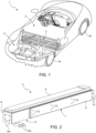
- reference numeral 1 indicates, as a whole, a road vehicle provided with two front wheels W and two rear wheels W.
- the road vehicle 1 is a vehicle powered at least partially electrically and is provided with a frame 2.
- the road vehicle 1 comprises a battery pack 3, in this example supported by the frame 2 inside an engine compartment 4.
- the battery pack is arranged at the back of a passenger compartment 5, for example at a vehicle floor, behind the seats contained inside the passenger compartment 5.
- FIG 2 shows an example of a battery pack 3 which can be improved according to the present invention.
- the battery pack 3 has a substantially elongated parallelepiped shape and can be arranged transversely to a longitudinal axis of the vehicle.
- the battery pack 3 is suitable for being connected to an electric propulsion system (not illustrated) of the vehicle 1 and is adapted to store the electric energy produced by an electric machine (not illustrated) or released by other sources.
- the battery pack 3 comprises at least one portion 6 configured to house a battery control and monitoring system 8 (normally called BMS - "Battery Management System"), adapted to control the operating parameters of the battery.
- BMS Battery Management System
- the battery comprises, as is known, a plurality of cells and the ends of such cells C are connected to terminals T at the portion 6.
- Two connectors CN project out of the control system 8, said connectors CN being configured to conduct current from and towards the control system 8.
- the battery pack 3 further comprises a portion 7 configured to house the electrochemical cells C (i.e.) the active material of the battery pack 3.
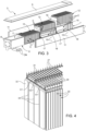
- the vehicle battery pack 3 comprises a support structure 15 comprising, in turn, at least two elongated perimeter elements 16 and 18 facing each other, which define between them a box-like portion BP.
- the battery pack 3 further comprises one or more bulkheads 17 arranged so as to divide the box-like portion BP delimiting at least two housings, in which the bulkheads 17 are arranged transversely to the two perimeter elements 16 and 18 facing each other.
- the perimeter elements 16 and 18 define two parallel planes, between which the bulkheads 17 extend transversely (perpendicularly).
- the bulkheads 17 delimit, inside the box-like portion BP, three different housings.
- the electrochemical cells C are of planar type, electrically connected and parallel both to one another and to the bulkheads 17 and divided, in this example, into three modules 12.
- the modules 12 each comprise at least two insertion plates 32, arranged at the ends of each module 12, parallel to the bulkheads 17, and configured to facilitate the insertion of each module 12 in compression inside the relative housing, so that the compression remains also following the insertion.
- the modules 12 of cells C are compressed outside the housing and inserted maintaining the compression.
- the cells C remain compressed between the two bulkheads 17 which delimit the respective housing.
- each insertion plate 32 comprises guiding elements 34 configured to direct the module 12 during the insertion into the respective housing.
- the battery pack 3 comprises a plurality of heat dissipating elements 20.
- each cell C comprises a pair of terminal poles TT', TT" (positive and negative, i.e. cathode and anode), extending from the same side of the cells C.
- the poles TT', TT'' are supported by a support 27 made of plastic material.
- the support 27 has a separator 29.
- the connection of the terminal poles TT', TT" is made at one or more connection planes 31.
- the battery pack 3 comprises at least one cooling panel 11, arranged at the at least one side surface and configured to be fixed to the support structure 15 by means of fixing elements 10, 10' so as to dissipate the heat transmitted by the dissipating elements 20.
- the battery pack 3 comprises a top opening, hermetically closed by a cover element 9.
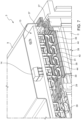
- Figure 5 shows an enlarged cutaway view of a detail of the battery pack of Figure 3 .
- a control unit 13 comprising a substrate 37 constrained to the cover 9 facing the connection planes 31 of the terminal poles TT', TT" of the cells.
- the substrate 37 supports a plurality of elements 14 configured to control the operating parameters of the electrochemical cells C of the module 12 (voltage, temperature, ).
- reference numeral 39 indicates elastically deformable conducting contact elements of the spring type for sensing the voltage of the cells.
- Such spring elements 39 are configured to be, in use, elastically compressed between the planar support substrate 37 and the plane 31 of the terminal poles TT', TT".
- a plurality of springs 39 is provided arranged in single rows so that more than one spring 39 is at the plane 31 of the terminal poles TT', TT'' of each electrochemical cell C.
- the coupling according to the prior art between the springs 39 and the plane 31 of the poles of the cells of the battery pack is schematized in Figure 5 .
- the coupling between the overlapped terminal poles TT' , TT" is made by means of a continuous welding line 40 which substantially develops along the entire length of the plane 31 and of the edge of the underlying cell.
- the contact of the springs 39 with the plane 31 thus occurs at the welding line 40 and this involves a series of drawbacks (described in the foregoing).
- Figure 6 shows an enlarged view of a detail of the battery pack of Figure 3 in which spring elements 39, described in the foregoing, are present for measuring the voltage of the cells and in such figure a first step of making a coupling according to the present invention between the springs and the poles of the cells of the battery pack in order to optimize the contact zone of the springs 39 is schematized.
- a welding is performed along the edge of the cell so as to make the coupling between the overlapped terminal poles TT', TT".
- the longitudinal welding line 41 is not continuous but made in the form of portions in series of welding alternated with portions in which the welding is not performed. In particular, such portions in which the welding is not performed are located at the space provided between two adjacent springs 39 of the same row.
- Reference numeral 42 identifies the portions unprovided with the longitudinal welding line 41.
- FIG 7 shows an enlarged view of the detail of the battery pack of Figure 6 in which a second step of making the coupling according to the present invention between the springs and the poles of the cells of the battery pack is schematized.
- the invention provides for the presence of a conductive plane 43 which covers the longitudinal welding line 41 and which makes an intermediate layer between the springs 39 and the underlying joining plane 31 joining the poles.
- the connection between such conductive plane 43 and the plane 31 is obtained by means of welding points or transverse welding lines 44 performed at the portions 42 previously left unprovided with the longitudinal welding line 41.
- the transverse welding lines 44 are located at the space between two adjacent springs 39 of the row and in this manner when the springs 39 are pressed towards the cells C, they are in contact with a surface zone without welding, namely the portions of the conductive plane 43 between the transverse welding lines 44.
- Figure 8 shows how the conductive plane 43 is supported by a handling structure 45 made of non-conductive material, in this case bridge-shaped, for allowing the operators to safely and precisely position the plane 43 on the poles of the cells.
Landscapes
- Chemical & Material Sciences (AREA)
- Chemical Kinetics & Catalysis (AREA)
- Electrochemistry (AREA)
- General Chemical & Material Sciences (AREA)
- Engineering & Computer Science (AREA)
- Aviation & Aerospace Engineering (AREA)
- Manufacturing & Machinery (AREA)
- Combustion & Propulsion (AREA)
- Transportation (AREA)
- Mechanical Engineering (AREA)
- Battery Mounting, Suspending (AREA)
- Connection Of Batteries Or Terminals (AREA)
Abstract
Description
- This patent application claims priority from
Italian patent application no. 102023000014934 filed on July 17, 2023 - The technical field of the present invention refers to the sector of electric-powered road vehicles. Such indication comprises both the road vehicles powered only electrically, and road vehicles powered both electrically and endothermically. Still more specifically, the present invention refers to a battery pack, namely a battery pack to be mounted in the aforementioned road vehicle and configured to store electric energy to be supplied during the electric propulsion. In such background, the present invention will deal with the problem of how to improve the monitoring of the voltage of the single cells forming the battery pack. Finally, the present invention also refers to a road vehicle comprising an aforementioned battery pack.
- In the automotive industry, and in particular with reference to the electric-powered road vehicles, it is known to utilize lithium batteries for storing electric energy to be supplied during the electric propulsion. In fact, such lithium batteries offer a high energy density ideal for implementing the electric power in the automotive industry. Currently, in fact, lithium polymers represent, from the chemical point of view, the state of the art in the production of high-capacity batteries. In such batteries, the interconnection in series and in parallel of various cells (generally, each of 3.7 V) is provided for reaching the desired total voltage and energy density for a battery pack. The battery modules usually available on the market (not only the automotive one, but also that of the consumer electronics) often comprise planar pouch batteries, which have a very limited thickness with respect to the other dimensions. Two very wide opposite faces (through which the heat is almost integrally dissipated) are identified, as well as four thin and elongated sides, wherein the positive and negative terminals of the cell are arranged on one side or on two opposite sides. Specifically, a known electric energy storage system for an electric-powered road vehicle comprises a battery pack consisting of a plurality of battery modules electrically connected to one another. Each battery module comprises, in turn, a support structure which carries a plurality of electrochemical cells electrically connected to one another in series and in parallel. In a known manner, also an electric connector is provided for connecting the battery pack to the propulsion system of the vehicle as well as a control unit (normally called BMS - "Battery Management System") which interacts with all of the battery modules so as to control and manage each cell or sets of electrochemical cells of each battery module.
- As is known, in such structure each electrochemical cell has a positive pole at an end and a negative pole at an opposite end (or at the same end) and the control unit (i.e. the BMS) connected to each pole of the electrochemical cells so as to control the voltage values of each electrochemical cell. Generally, the connection of the poles of the single electrochemical cells to the control unit occurs by means of a plurality of electric cables which extend inside the storage system. The presence of this plurality of electric cables complicates the structure and the assembly of the electric energy storage system, involves an increase in the volumes, in the bulks and in the weights of the electric energy storage system, and risks compromising the safety of the electric energy storage system, especially since there can be a significant voltage difference also in the order of several hundreds of Volts between the cables connecting the initial electrochemical cells of the battery pack and the cables connecting the final electrochemical cells of the battery pack.
-
EP4092795 , by the same Applicant of the present invention, describes an alternative solution to the aforementioned electric cables monitoring the voltage of the electrochemical cells of the battery pack. In brief, the solution described inEP4092795 provides for equipping the battery with a control unit directly facing the cells and on another side protected by a specially provided casing in which the sensor elements for sensing the voltage of the cells comprise a plurality of elastically deformable conductors, in practice a sort of spring elements, on one side directly fixed to the control unit and on the other side, in use, elastically compressed against the poles of the cell. For further details, reference is obviously made toEP4092795 since the structure of the battery pack described therein represents a starting point which can be improved thanks to the present invention. In particular, such improvement, as it will become clear, concerns the point of contact between the described spring elements and the poles of the cell because, as inferable, the measurement of the voltage of the cells, and thus the operation of the battery pack controlled by the control unit, are strictly linked to the "contact" between tab and the end of the spring. Currently, the free ends of the springs enter into contact with the cells at welds provided for connecting the poles to one another and through which the power of the battery passes. In such sense, these welds may not be eliminated, nor may they be reduced at will, because the performance of the overall battery module depends on them. Such known contact between springs and cell has some drawbacks. In fact, the welds can be bad current conductors and can also generate in the contact area the presence of impurities and roughness which can lead to the loss of contact or can ruin the covering of the springs thereby triggering undesired corrosion mechanisms. - Starting from such prior art, there is thus the current need to improve the contact zone between the aforementioned springs measuring the voltage and the poles of the cells so as to overcome the mentioned drawbacks.
- The object of the present invention is thus to provide a battery pack for an electric-powered road vehicle capable of overcoming the drawbacks described above. Besides the battery pack per se, the present invention also extends to the electric road vehicle equipped with such battery pack.
- Starting point of the present invention is a battery pack comprising:
- a plurality of electrochemical cells, preferably with lithium ion technology, in which the cells are planar and arranged in a pack pattern side by side so as to form at least one module; as is known, each cell comprises two terminal poles which according to the present invention are brought back at a first edge of the cell so that they can be easily connected to one another by a longitudinal welding line along the edge (as it will be evident, preferably a welding line with some interruptions for making a sort of dashed welding line). As is known, the length of the longitudinal welding may not be reduced at will because it must satisfy design specifications (the power of the battery passes through the welding) and thus the above-mentioned interruptions are only a few small sections of the length of the edge of the cells;
- a support (preferably in the form of a planar substrate made of non-conductive material) installed in the battery so as to have a separate face facing the terminal poles of the cells;
- a plurality of spring-conducting elements, namely elastically deformable conducting elements, having first ends coupled to the support and second ends intended to enter in contact (mediated contact, as it will become clear) with the poles so as to allow measuring the voltage of the cells or to power with current some external devices. In particular, the spring-conducting elements are arranged in rows parallel to one another in positions such that, when the battery pack is in use, each row of the spring-conducting elements is pressed against the terminal poles along the edge of a corresponding cell. In this manner, a conductive bridge is made between each cell and the support for measuring the voltage.
- Such structure is known, for example it is described in
EP4092795 by the same Applicant, and thus the person skilled in the art has no need for other details in order to understand the elements listed above. - Starting from such known structure, the present invention proposes to provide each cell with a further element, namely a conductive plane, which covers the terminal poles (is interposed between the poles and the corresponding row of spring-conducting elements), wherein each conductive plane is constrained to the corresponding terminal poles by means of points or transverse welding lines only in specific positions. Such welding points are in particular at the separation space provided between two adjacent spring-conducting elements of the same row so that, when the battery is in use and the spring-conducting elements are pressed against the conductive plane, the free ends of the springs are in contact with the conductive plane in zones unprovided with welding points or lines.
- The lengths of these welding points can be limited because the design characteristics (the passing of the power of the battery) are entrusted to the longitudinal welding line placed below the conductive plane, namely on the opposite side with respect to the springs. The fact that the springs are in contact with zones of a surface unprovided with welds allows overcoming the drawbacks mentioned with reference to the prior art. Furthermore, the conductive plane is thin and thus there are no undesired bulks.
- Preferably, as already mentioned in the foregoing, each longitudinal welding line connecting corresponding terminal poles is a non-continuous line along the entire edge of the cell but it is of the "dashed" type, namely has discontinuity points or welding gaps. The interruption points of the longitudinal welding line are not random but are exactly at the connecting points or connecting transverse welding lines made on the new conductive planes. In this manner, the points or transverse welding lines do not overlap with the longitudinal welding lines.
- Preferably, the terminal poles are made in the form of conductive plates overlapped along substantially the entire first edge of each cell.
- Preferably, the battery pack further comprises:
- a box-shaped support structure with a back wall, two side walls and an opening opposite the back wall from which the terminal poles of the cells are accessible;
- a cover coupled to the support structure at the opening; in this case, the support supporting the spring elements is in the form of a substrate coupled to the cover and facing the cells;
- at least one voltage sensing device of the cells supported by the support and connected to the spring elements for monitoring the voltage of each cell.
- As is clear, the innovative element provided by the present invention is the conductive plane covering the poles and the longitudinal welding line joining them. In order to enable the safe manoeuvrability and installation thereof in the battery, each conductive plane is coupled to a handling body made of non-conductive material. Preferably, each handling body made of non-conductive material comprises a bridge portion parallel to the corresponding conductive plane and two side portions configured to couple to corresponding elements of the battery pack and guarantee the correct positioning of the new conductive plane.
- Preferably, the new conductive planes, the spring-conducting elements, the terminal poles are made of the same conductive material.
- Finally, the present invention also extends to every electric-powered road vehicle in which a battery pack, as object of the appended claims, is installed. Preferably, the battery pack is arranged transversely to a longitudinal direction of the vehicle and is mounted on a frame at the back of a passenger compartment.
- The present invention will now be described with reference to the accompanying drawings, which illustrate some non-limiting example embodiments thereof, wherein:
-
Figure 1 is a schematic perspective view of an electric-powered vehicle which can be equipped with a battery pack in accordance with the present invention; -
Figure 2 is a schematic perspective view of a battery pack for an electric-powered vehicle which can be improved in accordance with the present invention; -
Figure 3 is an exploded view of the battery pack ofFigure 2 ; -
Figure 4 is an enlarged view of a detail of a module of the battery pack ofFigure 3 ; -
Figure 5 shows an enlarged view of a detail of the battery pack ofFigure 3 in which spring elements are present for measuring the voltage of the cells connecting the poles of the cells to a control unit; in such figure, the coupling according to the prior art between the springs and the poles of the cells of the battery pack is schematized; -
Figure 6 shows an enlarged view of a detail of the battery pack ofFigure 3 in which spring elements are present for measuring the voltage of the cells connecting the poles of the cells to the control unit; in such figure, a first step of making a coupling according to the present invention between the springs and the poles of the cells of the battery pack is schematized; -
Figure 7 shows an enlarged view of a detail of the battery pack ofFigure 3 in which spring elements are present for measuring the voltage of the cells connecting the poles of the cells to a control unit; in such figure, a second step of making the coupling according to the present invention between the springs and the poles of the cells of the battery pack is schematized; -
Figure 8 shows an enlarged view of an additional component which has been introduced in the battery pack for making the coupling according to the present invention between the springs and the poles of the cells of the battery pack. - Referring to
Figure 1 ,reference numeral 1 indicates, as a whole, a road vehicle provided with two front wheels W and two rear wheels W. Theroad vehicle 1 is a vehicle powered at least partially electrically and is provided with aframe 2. Theroad vehicle 1 comprises abattery pack 3, in this example supported by theframe 2 inside anengine compartment 4. As is visible, preferably the battery pack is arranged at the back of apassenger compartment 5, for example at a vehicle floor, behind the seats contained inside thepassenger compartment 5. -
Figure 2 shows an example of abattery pack 3 which can be improved according to the present invention. In this example, thebattery pack 3 has a substantially elongated parallelepiped shape and can be arranged transversely to a longitudinal axis of the vehicle. In particular, thebattery pack 3 is suitable for being connected to an electric propulsion system (not illustrated) of thevehicle 1 and is adapted to store the electric energy produced by an electric machine (not illustrated) or released by other sources. As is illustrated inFigures 2 and3 , thebattery pack 3 comprises at least oneportion 6 configured to house a battery control and monitoring system 8 (normally called BMS - "Battery Management System"), adapted to control the operating parameters of the battery. The battery comprises, as is known, a plurality of cells and the ends of such cells C are connected to terminals T at theportion 6. Two connectors CN project out of thecontrol system 8, said connectors CN being configured to conduct current from and towards thecontrol system 8. Thebattery pack 3 further comprises aportion 7 configured to house the electrochemical cells C (i.e.) the active material of thebattery pack 3. As is illustrated for example inFigure 3 , thevehicle battery pack 3 comprises asupport structure 15 comprising, in turn, at least twoelongated perimeter elements battery pack 3 further comprises one ormore bulkheads 17 arranged so as to divide the box-like portion BP delimiting at least two housings, in which thebulkheads 17 are arranged transversely to the twoperimeter elements perimeter elements bulkheads 17 extend transversely (perpendicularly). In the non-limiting embodiment ofFigure 3 , thebulkheads 17 delimit, inside the box-like portion BP, three different housings. The electrochemical cells C are of planar type, electrically connected and parallel both to one another and to thebulkheads 17 and divided, in this example, into threemodules 12. As is visible inFigure 4 , in this example themodules 12 each comprise at least twoinsertion plates 32, arranged at the ends of eachmodule 12, parallel to thebulkheads 17, and configured to facilitate the insertion of eachmodule 12 in compression inside the relative housing, so that the compression remains also following the insertion. In such manner, themodules 12 of cells C are compressed outside the housing and inserted maintaining the compression. By so doing, the cells C remain compressed between the twobulkheads 17 which delimit the respective housing. In this example, eachinsertion plate 32 comprises guidingelements 34 configured to direct themodule 12 during the insertion into the respective housing. As is visible in the example ofFigure 4 , thebattery pack 3 comprises a plurality ofheat dissipating elements 20. As is known and as is visible in the example ofFigure 4 , each cell C comprises a pair of terminal poles TT', TT" (positive and negative, i.e. cathode and anode), extending from the same side of the cells C. The poles TT', TT'' are supported by asupport 27 made of plastic material. In order to prevent the contact between two adjacent cells, thesupport 27 has aseparator 29. In particular, the connection of the terminal poles TT', TT" is made at one or more connection planes 31. - Going back to
Figure 2 , thebattery pack 3 comprises at least onecooling panel 11, arranged at the at least one side surface and configured to be fixed to thesupport structure 15 by means of fixingelements 10, 10' so as to dissipate the heat transmitted by the dissipatingelements 20. Thebattery pack 3 comprises a top opening, hermetically closed by acover element 9. -
Figure 5 shows an enlarged cutaway view of a detail of the battery pack ofFigure 3 . Such view shows the presence of acontrol unit 13 comprising asubstrate 37 constrained to thecover 9 facing the connection planes 31 of the terminal poles TT', TT" of the cells. Thesubstrate 37 supports a plurality ofelements 14 configured to control the operating parameters of the electrochemical cells C of the module 12 (voltage, temperature, ...). InFigure 5 ,reference numeral 39 indicates elastically deformable conducting contact elements of the spring type for sensing the voltage of the cells.Such spring elements 39 are configured to be, in use, elastically compressed between theplanar support substrate 37 and theplane 31 of the terminal poles TT', TT". For such purpose, a plurality ofsprings 39 is provided arranged in single rows so that more than onespring 39 is at theplane 31 of the terminal poles TT', TT'' of each electrochemical cell C. The coupling according to the prior art between thesprings 39 and theplane 31 of the poles of the cells of the battery pack is schematized inFigure 5 . In particular, the coupling between the overlapped terminal poles TT' , TT" is made by means of acontinuous welding line 40 which substantially develops along the entire length of theplane 31 and of the edge of the underlying cell. The contact of thesprings 39 with theplane 31 thus occurs at thewelding line 40 and this involves a series of drawbacks (described in the foregoing). -
Figure 6 shows an enlarged view of a detail of the battery pack ofFigure 3 in which springelements 39, described in the foregoing, are present for measuring the voltage of the cells and in such figure a first step of making a coupling according to the present invention between the springs and the poles of the cells of the battery pack in order to optimize the contact zone of thesprings 39 is schematized. As is visible inFigure 6 , also in this case, a welding is performed along the edge of the cell so as to make the coupling between the overlapped terminal poles TT', TT". However, in an innovative manner in this case thelongitudinal welding line 41 is not continuous but made in the form of portions in series of welding alternated with portions in which the welding is not performed. In particular, such portions in which the welding is not performed are located at the space provided between twoadjacent springs 39 of the same row.Reference numeral 42 identifies the portions unprovided with thelongitudinal welding line 41. -
Figure 7 shows an enlarged view of the detail of the battery pack ofFigure 6 in which a second step of making the coupling according to the present invention between the springs and the poles of the cells of the battery pack is schematized. As is visible in such figure, the invention provides for the presence of aconductive plane 43 which covers thelongitudinal welding line 41 and which makes an intermediate layer between thesprings 39 and the underlying joiningplane 31 joining the poles. The connection between suchconductive plane 43 and theplane 31 is obtained by means of welding points ortransverse welding lines 44 performed at theportions 42 previously left unprovided with thelongitudinal welding line 41. Therefore, thetransverse welding lines 44 are located at the space between twoadjacent springs 39 of the row and in this manner when thesprings 39 are pressed towards the cells C, they are in contact with a surface zone without welding, namely the portions of theconductive plane 43 between the transverse welding lines 44. This solution achieves the desired results because in this manner impurities and roughness deriving from the welding are not present in the contact area and therefore the possibility of loss of contact or of damage of the covering of the springs is reduced. - Finally,
Figure 8 shows how theconductive plane 43 is supported by ahandling structure 45 made of non-conductive material, in this case bridge-shaped, for allowing the operators to safely and precisely position theplane 43 on the poles of the cells.
Claims (10)
- Battery pack for an electric-powered road vehicle (1), wherein the battery pack (3) comprises:- a plurality of planar electrochemical cells (C) arranged in a pack pattern side by side; wherein each cell (C) comprises terminal poles (TT', TT") at a first edge;- a support (37) facing the terminal poles (TT', TT") of the cells (C);- a plurality of elastically deformable spring-conducting elements (39) having first ends coupled to the support (37),wherein the spring-conducting elements (39) are arranged in rows so that when the battery pack (3) is in use each row of the spring-conducting elements (39) is pressed against the terminal poles (TT', TT'') of a corresponding cell (C) to make a conductive bridge between each cell (C) and the support (37);wherein the terminal poles (TT', TT'') of each cell (C) are connected to one another by a longitudinal welding line (41) parallel to the first edge of the corresponding cell (C); characterized by the fact that:
for each cell (C) a conductive plane (43) is provided between the terminal poles (TT', TT") and the corresponding row of spring-conducting elements (39); wherein each conductive plane (43) is constrained to the corresponding terminal poles (TT', TT") by means of points or transverse welding lines (44) at the space provided between two adjacent spring-conducting elements (39) of the same row so that when the battery is in use the spring-conducting elements (39) are pressed against portions of the conductive planes (43) unprovided with welding points or lines. - Battery pack as claimed in claim 1, wherein for each cell (C) a joining plane (31) joining the terminal poles (TT', TT") is provided, wherein the longitudinal welding line (41) connecting the terminal poles (TT', TT'') of each cell (C) being made on the corresponding joining plane (31) below the conductive plane (43).
- Battery pack as claimed in claim 1 or 2, wherein each longitudinal welding line (41) connecting the corresponding terminal poles (TT', TT") is a dashed line, the points or transverse welding lines (44) connecting the conductive planes (43) to the terminal poles (TT', TT'') being at the gaps of the dashed longitudinal welding lines (41) so that the points or transverse welding lines (44) do not overlap with the longitudinal welding lines (41).
- Battery pack as claimed in any of the preceding claims, wherein the terminal poles (TT', TT") are made in the form of a conductive plate along substantially the entire first edge of each cell.
- Battery pack as claimed in any of the preceding claims, wherein the battery pack also comprises:- a box-shaped support structure (15) with a back wall and two side walls and an opening opposite the back wall from which the terminal poles (TT', TT") of the cells (C) are accessible;- a cover (9) coupled to the support structure (15) at the opening; the support (37) supporting the spring elements (39) being in the form of a substrate coupled to the cover (9) and facing the cells (C).- at least one voltage sensing device (14) of the cells (C) supported by the support (37) and connected to the spring elements (39) to monitor the voltage of each cell (C).
- Battery pack as claimed in any of the preceding claims, wherein each conductive plane (43) is coupled to a handling body (45) made of non-conductive material.
- Battery pack as claimed in claim 6, wherein the handling body (45) of non-conductive material comprises a bridge portion parallel to the corresponding conductive plane (43) and two side portions configured to couple to corresponding elements of the battery pack (3).
- Battery pack as claimed in any of the preceding claims, wherein the conductive planes (43), the spring-conducting elements (39), the terminal poles (TT', TT") are made of the same conductive material.
- Electric-powered road vehicle (1), wherein the vehicle (1) comprises a battery pack (3) according to any of the preceding claims.
- Vehicle as claimed in claim 9, wherein the battery pack (3) is arranged transversely to a longitudinal direction of the vehicle (1) and is mounted on a frame (2) at the back of a passenger compartment (5).
Applications Claiming Priority (1)
| Application Number | Priority Date | Filing Date | Title |
|---|---|---|---|
| IT102023000014934A IT202300014934A1 (en) | 2023-07-17 | 2023-07-17 | BATTERY PACK FOR AN ELECTRIC POWERED ROAD VEHICLE AND AN ELECTRIC POWERED ROAD VEHICLE EQUIPPED WITH SUCH A BATTERY PACK |
Publications (2)
| Publication Number | Publication Date |
|---|---|
| EP4496091A1 true EP4496091A1 (en) | 2025-01-22 |
| EP4496091B1 EP4496091B1 (en) | 2025-12-03 |
Family
ID=88291253
Family Applications (1)
| Application Number | Title | Priority Date | Filing Date |
|---|---|---|---|
| EP24187959.2A Active EP4496091B1 (en) | 2023-07-17 | 2024-07-11 | Battery pack for an electric-powered road vehicle and electric-powered road vehicle equipped with such a battery pack |
Country Status (5)
| Country | Link |
|---|---|
| US (1) | US20250030130A1 (en) |
| EP (1) | EP4496091B1 (en) |
| JP (1) | JP2025014119A (en) |
| CN (1) | CN119324285A (en) |
| IT (1) | IT202300014934A1 (en) |
Families Citing this family (1)
| Publication number | Priority date | Publication date | Assignee | Title |
|---|---|---|---|---|
| SE2150220A1 (en) * | 2021-03-01 | 2022-03-15 | Elonroad Ab | A housing for a sunken electric road track and a sunken electric road track |
Citations (6)
| Publication number | Priority date | Publication date | Assignee | Title |
|---|---|---|---|---|
| US20180108898A1 (en) * | 2016-10-17 | 2018-04-19 | Yazaki Corporation | Bus bar module |
| US11094974B2 (en) * | 2016-09-13 | 2021-08-17 | Yazaki Corporation | Voltage detector of battery module and battery pack |
| KR20220115077A (en) * | 2021-02-09 | 2022-08-17 | 몰렉스 엘엘씨 | Battery connection module |
| US20220367925A1 (en) * | 2021-05-17 | 2022-11-17 | Ferrari S.P.A. | Control unit, vehicular battery pack and relative assembly method |
| EP4092794A1 (en) * | 2021-05-17 | 2022-11-23 | FERRARI S.p.A. | Vehicular battery pack and relative assembly method |
| EP4092795A1 (en) | 2021-05-17 | 2022-11-23 | FERRARI S.p.A. | Control unit, vehicular battery pack and relative assembly method |
-
2023
- 2023-07-17 IT IT102023000014934A patent/IT202300014934A1/en unknown
-
2024
- 2024-07-08 US US18/765,879 patent/US20250030130A1/en active Pending
- 2024-07-11 EP EP24187959.2A patent/EP4496091B1/en active Active
- 2024-07-12 JP JP2024112110A patent/JP2025014119A/en active Pending
- 2024-07-16 CN CN202410953041.6A patent/CN119324285A/en active Pending
Patent Citations (6)
| Publication number | Priority date | Publication date | Assignee | Title |
|---|---|---|---|---|
| US11094974B2 (en) * | 2016-09-13 | 2021-08-17 | Yazaki Corporation | Voltage detector of battery module and battery pack |
| US20180108898A1 (en) * | 2016-10-17 | 2018-04-19 | Yazaki Corporation | Bus bar module |
| KR20220115077A (en) * | 2021-02-09 | 2022-08-17 | 몰렉스 엘엘씨 | Battery connection module |
| US20220367925A1 (en) * | 2021-05-17 | 2022-11-17 | Ferrari S.P.A. | Control unit, vehicular battery pack and relative assembly method |
| EP4092794A1 (en) * | 2021-05-17 | 2022-11-23 | FERRARI S.p.A. | Vehicular battery pack and relative assembly method |
| EP4092795A1 (en) | 2021-05-17 | 2022-11-23 | FERRARI S.p.A. | Control unit, vehicular battery pack and relative assembly method |
Also Published As
| Publication number | Publication date |
|---|---|
| IT202300014934A1 (en) | 2025-01-17 |
| CN119324285A (en) | 2025-01-17 |
| US20250030130A1 (en) | 2025-01-23 |
| EP4496091B1 (en) | 2025-12-03 |
| JP2025014119A (en) | 2025-01-29 |
Similar Documents
| Publication | Publication Date | Title |
|---|---|---|
| CN102804447B (en) | Battery module including novel structural sensing member | |
| US20220285755A1 (en) | Top Cooling Type Battery Pack | |
| JP5537111B2 (en) | Secondary battery device | |
| KR101371212B1 (en) | Battery module and cell-cartridge for battery module | |
| EP2562842B1 (en) | Battery module | |
| KR20190096674A (en) | Bus Bar Having Current Interruption Part and Battery Module Having the Same | |
| CN110337736B (en) | Battery pack, bracket | |
| EP4160783B1 (en) | Battery pack | |
| EP3688826B1 (en) | Battery pack including cell restraint | |
| US10818958B2 (en) | Battery cell and battery system | |
| KR20150034495A (en) | Voltage Sensing Assembly and Battery Module Including the Same | |
| US20210021007A1 (en) | Battery module including internal plate | |
| CN113767513A (en) | Battery pack including connection plate, electronic device, and vehicle | |
| US20190280353A1 (en) | Cell Pack | |
| JP2022552154A (en) | Battery pack with improved vibration resistance | |
| EP4496091B1 (en) | Battery pack for an electric-powered road vehicle and electric-powered road vehicle equipped with such a battery pack | |
| US10069120B2 (en) | Battery module | |
| US10461305B2 (en) | Battery cell and battery system | |
| JP2012033299A (en) | Power storage device | |
| WO2019244413A1 (en) | Battery pack | |
| JP2007059279A (en) | Battery housing and battery pack | |
| US20250183393A1 (en) | Battery pack for a road vehicle with electric propulsion and electrically propelled road vehicle provided with said battery pack | |
| CN110291658A (en) | Battery cells and battery modules | |
| KR102925167B1 (en) | Battery module and battery pack including the same and vehicle including the same | |
| EP4576411A1 (en) | Battery pack and vehicle including same |
Legal Events
| Date | Code | Title | Description |
|---|---|---|---|
| PUAI | Public reference made under article 153(3) epc to a published international application that has entered the european phase |
Free format text: ORIGINAL CODE: 0009012 |
|
| STAA | Information on the status of an ep patent application or granted ep patent |
Free format text: STATUS: THE APPLICATION HAS BEEN PUBLISHED |
|
| AK | Designated contracting states |
Kind code of ref document: A1 Designated state(s): AL AT BE BG CH CY CZ DE DK EE ES FI FR GB GR HR HU IE IS IT LI LT LU LV MC ME MK MT NL NO PL PT RO RS SE SI SK SM TR |
|
| STAA | Information on the status of an ep patent application or granted ep patent |
Free format text: STATUS: REQUEST FOR EXAMINATION WAS MADE |
|
| 17P | Request for examination filed |
Effective date: 20250522 |
|
| GRAP | Despatch of communication of intention to grant a patent |
Free format text: ORIGINAL CODE: EPIDOSNIGR1 |
|
| STAA | Information on the status of an ep patent application or granted ep patent |
Free format text: STATUS: GRANT OF PATENT IS INTENDED |
|
| RIC1 | Information provided on ipc code assigned before grant |
Ipc: H01M 50/209 20210101AFI20250606BHEP Ipc: H01M 50/249 20210101ALI20250606BHEP Ipc: H01M 50/502 20210101ALI20250606BHEP Ipc: H01M 50/503 20210101ALI20250606BHEP Ipc: H01M 50/507 20210101ALI20250606BHEP Ipc: H01M 50/514 20210101ALI20250606BHEP Ipc: H01M 10/48 20060101ALI20250606BHEP |
|
| INTG | Intention to grant announced |
Effective date: 20250701 |
|
| GRAS | Grant fee paid |
Free format text: ORIGINAL CODE: EPIDOSNIGR3 |
|
| GRAA | (expected) grant |
Free format text: ORIGINAL CODE: 0009210 |
|
| STAA | Information on the status of an ep patent application or granted ep patent |
Free format text: STATUS: THE PATENT HAS BEEN GRANTED |
|
| AK | Designated contracting states |
Kind code of ref document: B1 Designated state(s): AL AT BE BG CH CY CZ DE DK EE ES FI FR GB GR HR HU IE IS IT LI LT LU LV MC ME MK MT NL NO PL PT RO RS SE SI SK SM TR |
|
| REG | Reference to a national code |
Ref country code: CH Ref legal event code: F10 Free format text: ST27 STATUS EVENT CODE: U-0-0-F10-F00 (AS PROVIDED BY THE NATIONAL OFFICE) Effective date: 20251203 Ref country code: GB Ref legal event code: FG4D |
|
| REG | Reference to a national code |
Ref country code: DE Ref legal event code: R096 Ref document number: 602024001513 Country of ref document: DE |
|
| REG | Reference to a national code |
Ref country code: IE Ref legal event code: FG4D |
|
| REG | Reference to a national code |
Ref country code: NL Ref legal event code: MP Effective date: 20251203 |
|
| PG25 | Lapsed in a contracting state [announced via postgrant information from national office to epo] |
Ref country code: ES Free format text: LAPSE BECAUSE OF FAILURE TO SUBMIT A TRANSLATION OF THE DESCRIPTION OR TO PAY THE FEE WITHIN THE PRESCRIBED TIME-LIMIT Effective date: 20251203 |
|
| REG | Reference to a national code |
Ref country code: LT Ref legal event code: MG9D |
|
| PG25 | Lapsed in a contracting state [announced via postgrant information from national office to epo] |
Ref country code: NO Free format text: LAPSE BECAUSE OF FAILURE TO SUBMIT A TRANSLATION OF THE DESCRIPTION OR TO PAY THE FEE WITHIN THE PRESCRIBED TIME-LIMIT Effective date: 20260303 |
|
| PG25 | Lapsed in a contracting state [announced via postgrant information from national office to epo] |
Ref country code: FI Free format text: LAPSE BECAUSE OF FAILURE TO SUBMIT A TRANSLATION OF THE DESCRIPTION OR TO PAY THE FEE WITHIN THE PRESCRIBED TIME-LIMIT Effective date: 20251203 Ref country code: HR Free format text: LAPSE BECAUSE OF FAILURE TO SUBMIT A TRANSLATION OF THE DESCRIPTION OR TO PAY THE FEE WITHIN THE PRESCRIBED TIME-LIMIT Effective date: 20251203 |
|
| PG25 | Lapsed in a contracting state [announced via postgrant information from national office to epo] |
Ref country code: RS Free format text: LAPSE BECAUSE OF FAILURE TO SUBMIT A TRANSLATION OF THE DESCRIPTION OR TO PAY THE FEE WITHIN THE PRESCRIBED TIME-LIMIT Effective date: 20260303 |
|
| PG25 | Lapsed in a contracting state [announced via postgrant information from national office to epo] |
Ref country code: PL Free format text: LAPSE BECAUSE OF FAILURE TO SUBMIT A TRANSLATION OF THE DESCRIPTION OR TO PAY THE FEE WITHIN THE PRESCRIBED TIME-LIMIT Effective date: 20251203 |
|
| PG25 | Lapsed in a contracting state [announced via postgrant information from national office to epo] |
Ref country code: LV Free format text: LAPSE BECAUSE OF FAILURE TO SUBMIT A TRANSLATION OF THE DESCRIPTION OR TO PAY THE FEE WITHIN THE PRESCRIBED TIME-LIMIT Effective date: 20251203 |