EP4496090A2 - Battery pack - Google Patents
Battery pack Download PDFInfo
- Publication number
- EP4496090A2 EP4496090A2 EP24186884.3A EP24186884A EP4496090A2 EP 4496090 A2 EP4496090 A2 EP 4496090A2 EP 24186884 A EP24186884 A EP 24186884A EP 4496090 A2 EP4496090 A2 EP 4496090A2
- Authority
- EP
- European Patent Office
- Prior art keywords
- battery
- battery cells
- battery pack
- reinforcement cover
- cover
- Prior art date
- Legal status (The legal status is an assumption and is not a legal conclusion. Google has not performed a legal analysis and makes no representation as to the accuracy of the status listed.)
- Pending
Links
Images


Classifications
-
- H—ELECTRICITY
- H01—ELECTRIC ELEMENTS
- H01M—PROCESSES OR MEANS, e.g. BATTERIES, FOR THE DIRECT CONVERSION OF CHEMICAL ENERGY INTO ELECTRICAL ENERGY
- H01M50/00—Constructional details or processes of manufacture of the non-active parts of electrochemical cells other than fuel cells, e.g. hybrid cells
- H01M50/20—Mountings; Secondary casings or frames; Racks, modules or packs; Suspension devices; Shock absorbers; Transport or carrying devices; Holders
- H01M50/271—Lids or covers for the racks or secondary casings
- H01M50/273—Lids or covers for the racks or secondary casings characterised by the material
- H01M50/276—Inorganic material
-
- H—ELECTRICITY
- H01—ELECTRIC ELEMENTS
- H01M—PROCESSES OR MEANS, e.g. BATTERIES, FOR THE DIRECT CONVERSION OF CHEMICAL ENERGY INTO ELECTRICAL ENERGY
- H01M50/00—Constructional details or processes of manufacture of the non-active parts of electrochemical cells other than fuel cells, e.g. hybrid cells
- H01M50/30—Arrangements for facilitating escape of gases
-
- H—ELECTRICITY
- H01—ELECTRIC ELEMENTS
- H01M—PROCESSES OR MEANS, e.g. BATTERIES, FOR THE DIRECT CONVERSION OF CHEMICAL ENERGY INTO ELECTRICAL ENERGY
- H01M10/00—Secondary cells; Manufacture thereof
- H01M10/60—Heating or cooling; Temperature control
- H01M10/65—Means for temperature control structurally associated with the cells
- H01M10/658—Means for temperature control structurally associated with the cells by thermal insulation or shielding
-
- H—ELECTRICITY
- H01—ELECTRIC ELEMENTS
- H01M—PROCESSES OR MEANS, e.g. BATTERIES, FOR THE DIRECT CONVERSION OF CHEMICAL ENERGY INTO ELECTRICAL ENERGY
- H01M50/00—Constructional details or processes of manufacture of the non-active parts of electrochemical cells other than fuel cells, e.g. hybrid cells
- H01M50/20—Mountings; Secondary casings or frames; Racks, modules or packs; Suspension devices; Shock absorbers; Transport or carrying devices; Holders
- H01M50/204—Racks, modules or packs for multiple batteries or multiple cells
-
- H—ELECTRICITY
- H01—ELECTRIC ELEMENTS
- H01M—PROCESSES OR MEANS, e.g. BATTERIES, FOR THE DIRECT CONVERSION OF CHEMICAL ENERGY INTO ELECTRICAL ENERGY
- H01M50/00—Constructional details or processes of manufacture of the non-active parts of electrochemical cells other than fuel cells, e.g. hybrid cells
- H01M50/20—Mountings; Secondary casings or frames; Racks, modules or packs; Suspension devices; Shock absorbers; Transport or carrying devices; Holders
- H01M50/233—Mountings; Secondary casings or frames; Racks, modules or packs; Suspension devices; Shock absorbers; Transport or carrying devices; Holders characterised by physical properties of casings or racks, e.g. dimensions
- H01M50/236—Hardness
-
- H—ELECTRICITY
- H01—ELECTRIC ELEMENTS
- H01M—PROCESSES OR MEANS, e.g. BATTERIES, FOR THE DIRECT CONVERSION OF CHEMICAL ENERGY INTO ELECTRICAL ENERGY
- H01M50/00—Constructional details or processes of manufacture of the non-active parts of electrochemical cells other than fuel cells, e.g. hybrid cells
- H01M50/20—Mountings; Secondary casings or frames; Racks, modules or packs; Suspension devices; Shock absorbers; Transport or carrying devices; Holders
- H01M50/271—Lids or covers for the racks or secondary casings
-
- H—ELECTRICITY
- H01—ELECTRIC ELEMENTS
- H01M—PROCESSES OR MEANS, e.g. BATTERIES, FOR THE DIRECT CONVERSION OF CHEMICAL ENERGY INTO ELECTRICAL ENERGY
- H01M50/00—Constructional details or processes of manufacture of the non-active parts of electrochemical cells other than fuel cells, e.g. hybrid cells
- H01M50/20—Mountings; Secondary casings or frames; Racks, modules or packs; Suspension devices; Shock absorbers; Transport or carrying devices; Holders
- H01M50/271—Lids or covers for the racks or secondary casings
- H01M50/273—Lids or covers for the racks or secondary casings characterised by the material
-
- H—ELECTRICITY
- H01—ELECTRIC ELEMENTS
- H01M—PROCESSES OR MEANS, e.g. BATTERIES, FOR THE DIRECT CONVERSION OF CHEMICAL ENERGY INTO ELECTRICAL ENERGY
- H01M50/00—Constructional details or processes of manufacture of the non-active parts of electrochemical cells other than fuel cells, e.g. hybrid cells
- H01M50/30—Arrangements for facilitating escape of gases
- H01M50/342—Non-re-sealable arrangements
-
- H—ELECTRICITY
- H01—ELECTRIC ELEMENTS
- H01M—PROCESSES OR MEANS, e.g. BATTERIES, FOR THE DIRECT CONVERSION OF CHEMICAL ENERGY INTO ELECTRICAL ENERGY
- H01M50/00—Constructional details or processes of manufacture of the non-active parts of electrochemical cells other than fuel cells, e.g. hybrid cells
- H01M50/30—Arrangements for facilitating escape of gases
- H01M50/35—Gas exhaust passages comprising elongated, tortuous or labyrinth-shaped exhaust passages
- H01M50/358—External gas exhaust passages located on the battery cover or case
-
- H—ELECTRICITY
- H01—ELECTRIC ELEMENTS
- H01M—PROCESSES OR MEANS, e.g. BATTERIES, FOR THE DIRECT CONVERSION OF CHEMICAL ENERGY INTO ELECTRICAL ENERGY
- H01M50/00—Constructional details or processes of manufacture of the non-active parts of electrochemical cells other than fuel cells, e.g. hybrid cells
- H01M50/30—Arrangements for facilitating escape of gases
- H01M50/35—Gas exhaust passages comprising elongated, tortuous or labyrinth-shaped exhaust passages
- H01M50/367—Internal gas exhaust passages forming part of the battery cover or case; Double cover vent systems
-
- H—ELECTRICITY
- H01—ELECTRIC ELEMENTS
- H01M—PROCESSES OR MEANS, e.g. BATTERIES, FOR THE DIRECT CONVERSION OF CHEMICAL ENERGY INTO ELECTRICAL ENERGY
- H01M50/00—Constructional details or processes of manufacture of the non-active parts of electrochemical cells other than fuel cells, e.g. hybrid cells
- H01M50/20—Mountings; Secondary casings or frames; Racks, modules or packs; Suspension devices; Shock absorbers; Transport or carrying devices; Holders
- H01M50/204—Racks, modules or packs for multiple batteries or multiple cells
- H01M50/207—Racks, modules or packs for multiple batteries or multiple cells characterised by their shape
- H01M50/209—Racks, modules or packs for multiple batteries or multiple cells characterised by their shape adapted for prismatic or rectangular cells
-
- Y—GENERAL TAGGING OF NEW TECHNOLOGICAL DEVELOPMENTS; GENERAL TAGGING OF CROSS-SECTIONAL TECHNOLOGIES SPANNING OVER SEVERAL SECTIONS OF THE IPC; TECHNICAL SUBJECTS COVERED BY FORMER USPC CROSS-REFERENCE ART COLLECTIONS [XRACs] AND DIGESTS
- Y02—TECHNOLOGIES OR APPLICATIONS FOR MITIGATION OR ADAPTATION AGAINST CLIMATE CHANGE
- Y02E—REDUCTION OF GREENHOUSE GAS [GHG] EMISSIONS, RELATED TO ENERGY GENERATION, TRANSMISSION OR DISTRIBUTION
- Y02E60/00—Enabling technologies; Technologies with a potential or indirect contribution to GHG emissions mitigation
- Y02E60/10—Energy storage using batteries
Definitions
- Embodiments relate to a battery pack capable of, upon occurrence of a predetermined event in a certain battery cell, reducing propagation of heat to a cell adjacent thereto.
- a secondary battery is a battery that is chargeable and dischargeable, unlike a primary battery that is not rechargeable.
- a low-capacity secondary battery in which one battery cell is packaged in the form of a pack is used in portable small-sized electronic devices, such as cellular phones and camcorders, and a large-capacity secondary battery in which dozens of battery cells are connected to each other in a battery pack is widely used as power sources for driving motors in hybrid vehicles and the like.
- a secondary battery may include an electrode assembly including a positive electrode plate, a negative electrode plate, and a separator between the positive and negative electrode plates.
- the electrode assembly and an electrolyte are accommodated in a case, and a cap plate is mounted on the case.
- the electrode assembly may be a wound electrode assembly or a stacked electrode assembly. In such an electrode assembly, an electrode tab may protrude in an upward or lateral direction, and a current collector may be connected to the electrode tab.
- a secondary battery has recently been applied to high-output products, such as electric vehicles and energy storage systems (ESSs).
- ESSs electric vehicles and energy storage systems
- a plurality of secondary batteries may be provided in the form of a battery pack.
- Embodiments provide a battery pack capable of, upon occurrence of a predetermined event in a certain battery cell, reducing propagation of heat to a cell adjacent thereto.
- a battery pack includes battery cells and a cover member configured to cover the battery cells and including a reinforcement cover on the battery cells.
- the reinforcement cover includes flange portions arranged in two rows at a central part of the reinforcement cover and extending in the arrangement direction of the battery cells.
- the flange portions may be located at positions corresponding to opposite sides of vents of the battery cells.
- the reinforcement cover may further include a plate portion covering upper surfaces of the battery cells, and the flange portions may have a bent shape and may be coupled to an upper surface of the plate portion.
- the flange portions may include at least one of steel, stainless steel, or aluminum.
- the flange portions may have a thickness in a range from approximately 1 mm to approximately 2 mm.
- the reinforcement cover may further include vent protruding portions between the flange portions and corresponding to the vents of the battery cells.
- the vent protruding portions may protrude upward at positions corresponding to the positions of the vents.
- the vent protruding portions may have a thickness in a range from approximately 1 mm to approximately 2 mm.
- the reinforcement cover may further include support portions on both ends of the reinforcement cover in the width direction of the battery cells and may protrude and be spaced apart from each other in the arrangement direction of the battery cells.
- the reinforcement cover may further include ventilation portions between the support portions that protrude to a height lower than the support portions.
- each of the battery cells may include a terminal provided on a side portion thereof on which the reinforcement cover is not present.
- the battery pack may further include a heat blocking member between the battery cells and the reinforcement cover.
- each of the battery cells may include a terminal provided on an upper side thereof on which the reinforcement cover is present.
- the battery pack may further include a heat blocking member located outside of the reinforcement cover and covering the terminal of each of the battery cells.
- the width of the reinforcement cover may be smaller than the width of each of the plurality of battery cells.
- Embodiments are provided to more fully illustrate the disclosure to a person having ordinary skill in the art, and the following embodiments may be modified in various other forms, and the scope of the disclosure is not limited to the following embodiments.
- the embodiments are provided to make the disclosure more faithful and complete and to completely convey the idea of the disclosure fully to those skilled in the art.
- the thickness or size of each layer is exaggerated for convenience and clarity of description, and same reference symbols in the drawings refer to the same elements.
- the term “and/or” includes any one of the enumerated items and any combination of one or more thereof.
- the term “connected” refers not only to direct connection between members A and B but also to indirect connection between members A and B with member C interposed therebetween.
- first and second are used herein to describe various members, parts, regions, layers, and/or portions, the members, the parts, the regions, the layers, and/or the portions are not to be limited by the terms. The terms are used only to distinguish one member, one part, one region, one layer, or one portion from another member, another part, another region, another layer, or another portion.
- a first member, a first part, a first region, a first layer, or a first portion hereinafter described may refer to a second member, a second part, a second region, a second layer, or a second portion without departing from the teachings of the disclosure.
- a battery pack may include at least one battery module and a pack housing including an accommodation space defined therein to accommodate the at least one battery module.
- the battery module may include a plurality of battery cells and a module housing.
- the battery cells may be accommodated in the module housing in a stacked form.
- Each of the battery cells may include a positive electrode lead and a negative electrode lead.
- the battery cells may be classified as a cylindrical type, a prismatic type, and/or a pouch type, depending on the type of battery.
- one cell stack in which battery cells are stacked may constitute one module in the battery pack.
- the cell stack may be accommodated in the accommodation space in the pack housing or may be accommodated in an accommodation space defined by a frame, a partition wall, etc.
- the battery cells may generate a large amount of heat during charging/discharging.
- the generated heat may accumulate in the battery cells and may accelerate deterioration of the battery cells.
- the battery pack may further include a cooling member in order to suppress deterioration of the battery cells.
- the cooling member may be disposed on the bottom of the accommodation space in which the battery cells are provided. However, the embodiments are not limited thereto.
- the cooling member may be disposed on the top or side surface of the accommodation space, depending on the battery pack.
- Gas generated in the battery cells under an abnormal operating condition also known as thermal runaway or a thermal event, may be discharged outside the battery cells.
- the battery pack or the battery module may be provided with an exhaust port for discharge of exhaust gas in order to suppress damage thereto due to exhaust gas.
- the battery pack may include a battery and a battery management system (BMS) configured to manage the battery.
- BMS battery management system
- the battery management system may include a detection device, a balancing device, and a control device.
- the battery module may include a plurality of cells connected to each other in series or in parallel.
- a plurality of battery modules may be connected to each other in series or in parallel.
- the detection device may detect the state (voltage, current, temperature, etc.) of the battery to obtain state information indicating the state of the battery.
- the detection device may detect the voltage of each of the cells or each of the battery modules constituting the battery.
- the detection device may detect the current flowing through each of the battery modules constituting the battery or the battery pack.
- the detection device may detect the temperature of the cells and/or the modules and/or ambient temperature at at least one point in the battery.
- the balancing device may perform balancing operation on the battery modules and/or the cells constituting the battery.
- the control device may receive the state information indicating the state (voltage, current, temperature, etc.) of the battery modules from the detection device.
- the control device may monitor and calculate the state (voltage, current, temperature, state of charge (SOC), state of health (SOH), etc.) of the battery modules based on the state information received from the detection device.
- the control device may perform a control function (e.g., temperature control, balancing control, charging/discharging control, etc.) and a protection function (e.g., overdischarge prevention, overcharge prevention, overcurrent prevention, short circuit prevention, fire extinguishing, etc.) based on a result of monitoring the state of the battery modules.
- the control device may perform a function of executing wired or wireless communication with an external device (e.g., an upper-level controller, a vehicle, a charger, a power conversion system (PCS), etc.) located outside the battery pack.
- an external device e.g., an upper-level controller, a vehicle,
- the control device may control charging/discharging operation and protection operation of the battery.
- the control device may include a charging/discharging controller, a balancing controller, and a protection unit.
- the battery management system may be a system that monitors the state of the battery and performs diagnosis, control, communication, and protection functions.
- the battery management system may calculate the state of charge/discharge of the battery, may calculate the lifespan or the state of health (SOH) of the battery, may interrupt supply of power from the battery (perform relay control) as needed, may perform thermal management control (cooling, heating, etc.), may perform a high-voltage interlock function, and may detect or calculate insulation and short circuit states.
- SOH state of health
- the relay may be a mechanical contactor that is turned on or off by a magnetic force of a coil or it may be a semiconductor switch such as a metal oxide semiconductor field effect transistor (MOSFET).
- MOSFET metal oxide semiconductor field effect transistor
- Relay control may be a function of interrupting supply of power from the battery when a problem occurs in the vehicle and/or the battery system.
- One or more relays and precharge relays may be provided at each of a positive electrode terminal and a negative electrode terminal.
- An in-rush current may be generated in a high-voltage capacitor on an input side of an inverter at the time of connection to the battery load.
- Precharge control may be a function of performing connection to a precharge resistor by operating the precharge relay before connection of the main relay in order to prevent draw of the in-rush current at the time of startup of the vehicle.
- a high-voltage interlock may be a detection circuit that uses a small signal in order to check whether all high-voltage components are connected to the entire vehicle system.
- the high-voltage interlock function may be a function of forcibly opening the relay when any one part of the entire loop is in an open state.
- FIG. 1 is a perspective view of a battery pack according to an embodiment.
- FIG. 2 is an exploded perspective view of the battery pack according to the embodiment.
- FIG. 3 is an enlarged view of portion A in FIG. 1 .
- the battery pack 100 may include a plurality of battery cells 110 and a cover member 120 coupled to the battery cells 110 and covering the outer surfaces of the battery cells 110.
- the battery pack 100 may further include a heat blocking member 130 between the battery cells 110 and the cover member 120 (see Figure 2 ).
- the plurality of battery cells 110 may be arranged in one direction as shown.
- Each of the battery cells 110 may include an electrode assembly.
- the electrode assembly may include a first electrode plate, a separator, and a second electrode plate, each of which is formed in a thin plate shape or a membrane shape.
- the first electrode plate, the separator, and the second electrode plate may be stacked or wound.
- the first electrode plate may be a negative electrode
- the second electrode plate may be a positive electrode.
- the first electrode plate may be a positive electrode
- the second electrode plate may be a negative electrode.
- the first electrode plate may be formed by applying a first electrode active material, such as graphite or carbon, to a first electrode current collector formed as a metal foil made of copper or nickel, and may include a first electrode uncoated portion, which is an area to which the first electrode active material is not applied.
- the first electrode uncoated portion may provide a passage for the flow of current between the first electrode plate and the outside.
- the second electrode plate may be formed by applying a second electrode active material, such as a transition metal oxide, to a second electrode current collector formed as a metal foil made of aluminum, and may include a second electrode uncoated portion, which is an area to which the second electrode active material is not applied.
- a second electrode active material such as a transition metal oxide
- the separator may be between the first electrode plate and the second electrode plate to prevent a short circuit and to enable the movement of lithium ions.
- the separator may be a film made of polyethylene, polypropylene, or a combination thereof.
- the electrode assembly may be accommodated in a case together with an electrolyte (optional).
- the electrolyte may include an organic solvent such as ethylene carbonate (EC), propylene carbonate (PC), diethyl carbonate (DEC), ethyl methyl carbonate (EMC), or dimethyl carbonate (DMC) and a lithium salt such as LiPF 6 or LiBF 4 .
- the case may be sealed by a component such as a cap plate or a side plate.
- FIG. 1 illustrates an embodiment in which the case is sealed by a side plate, and electrode terminals 111, which are coupled to the first electrode plate and the second electrode plate, are formed on both sides of the side plate.
- the electrode terminals 111 may protrude from both sides (e.g., opposite sides) of the case.
- each of the battery cells 110 may include a vent 112 in an upper surface thereof.
- the vent 112 may be thinner than the other regions of the battery cell 110 and thus may be configured to be opened (to rupture) earlier than the other regions of the battery cell 110 when an internal pressure in the battery cell 110 is equal to or higher than a reference pressure.
- the vent 112 may serve to guide internal gas in the battery cell 110 to be discharged to the outside in response to the internal pressure in the battery cell 110 being equal to or higher than the reference pressure, thereby preventing an accident such as an explosion.
- structures such as bus bars may be provided for electrical connection between the battery cells through the electrode terminals 111 formed on the side portions of the battery cells.
- the structures typically will not be affected by opening of the vent 112 of the battery cell 110.
- a spacer may be between every two adjacent ones of the battery cells 110.
- the spacer may serve to allow adjacent battery cells to be electrically isolated from each other and to block propagation of heat from one battery cell to another battery cell adjacent thereto.
- the cover member 120 may surround the battery cells 110 to protect the battery cells 110 from external impact.
- the cover member 120 may include a lower cover 121 under the battery cells 110, side covers 122 along the side surfaces of the battery cells 110, end covers 123 coupled to the foremost (frontmost) and rearmost battery cells among the battery cells 110, and a reinforcement cover 124 over or on the battery cells 110. In some embodiments, these covers may be referred to as plates.
- the lower cover 121 may extend along surfaces of the plurality of battery cells 110, for example, the lower surfaces of the battery cells 110.
- the lower cover 121 may support loads of the battery cells 110 and the heat blocking member 130.
- the lower cover 121 may also be configured to dissipate heat generated in the battery cells 110 through the lower surface of the battery pack 100.
- the side covers 122 may be above the lower cover 121 and may be coupled to both side surfaces of the battery cells 110 in the direction in which the battery cells 110 are arranged, thereby fixing the positions of the battery cells 110.
- the electrode terminals 111 of the battery cells 110 may be exposed through the side covers 122, and separate bus bars may be coupled to the electrode terminals 111 to electrically connect the battery cells 110 to each other.
- the end covers 123 may be coupled to the foremost (frontmost) and rearmost battery cells among the battery cells 110.
- the end covers 123 may fix the positions of the battery cells 110 and press the foremost (frontmost) and rearmost battery cells among the battery cells 110.
- the end covers 123 may be coupled to the lower cover 121, the side covers 122, and the reinforcement cover 124, and the battery cells 110 may be accommodated in an internal space defined by these covers 121, 122, 123, and 124.
- the reinforcement cover 124 may be coupled to the upper surfaces of the battery cells 110.
- the reinforcement cover 124 may protect the upper surfaces of the battery cells 110 and provide mechanical rigidity thereto.
- the reinforcement cover 124 may be made of steel. In other embodiments, the reinforcement cover 124 may be made of stainless steel or aluminum.
- the reinforcement cover 124 may include open holes in regions corresponding to the vents of the battery cells 110. Because the reinforcement cover 124 does not interfere with the vents due to the open holes in the reinforcement cover 124, operation of the vents of the battery cells 110 typically will not be inhibited.
- the reinforcement cover 124 may include a plate portion 124a, support portions 124b on both edges of the plate portion 124a and arranged in the longitudinal direction of the plate portion 124a, ventilation portions 124c on both edges of the plate portion 124a and arranged in the longitudinal direction of the plate portion 124a, two rows of flange portions 124d at the central part of the plate portion 124a and spaced apart from each other in the width direction of the plate portion 124a, and vent protruding portions 124e between the flange portions 124d and corresponding to the vents 112 of the battery cells 110.
- the plate portion 124a may have a substantially flat shape and may completely (or substantially completely) cover the upper surfaces of the battery cells 110.
- the support portions 124b may be on both edges of the plate portion 124a and may be arranged in the longitudinal direction of the plate portion 124a.
- the support portions 124b may be spaced apart from each other and may protrude farther upward than the plate portion 124a.
- the ventilation portions 124c may be between the support portions 124c along both edges of the plate portion 124a and may protrude farther upward than the plate portion 124a.
- the ventilation portions 124c may be lower than the support portions 124b in order to allow gases generated upon occurrence of an event in the battery cell 110 to move along the ventilation portions 124c on the upper surface of the plate portion 124a.
- Gas movement passages defined by the ventilation portions 125c may be on the upper surface of the plate portion 124a in the longitudinal direction of the plate portion 124a in the width direction of the plate portion 124a perpendicular to the longitudinal direction thereof, and thus gases may be easily moved and discharged to the outside of the battery pack 100.
- the flange portions 124d may be arranged in two rows at the central part of the plate portion 124a in order to provide rigidity to the reinforcement cover 124.
- the flange portions 124d may be separate components and they may each have, or they may be formed to be bent in, a substantially L-shape.
- the flange portions 124d may be coupled to the plate portion 124a.
- the flange portions 124d having this L-shape may more reliably provide rigidity to the entirety of the reinforcement cover 124 and may prevent (or at least mitigate) sagging of the reinforcement cover 124.
- the flange portions 124d may have a thickness of about (approximately) 1 mm to about (approximately) 2 mm. If the thickness of the flange portions 124d is equal to or greater than 1 mm, it may be possible to achieve the required rigidity, and if the thickness of the flange portions 124d is equal to or less than 2 mm, it may be suitable for reduction of the overall weight of the battery pack 100.
- the vent protruding portions 124e may be located at positions corresponding to the positions of the respective vents 112 of the battery cells 110.
- the vent protruding portions 124e may provide rigidity to the peripheries of the vents 112 of the battery cells 110.
- the vent protruding portions 124e may protrude upward along the peripheries of the vents 112, which are formed in the upper surfaces of the battery cells 110 so as to have a relatively small thickness, thereby protecting the vents 112 from external forces that may be applied to the vents 112.
- vent protruding portions 124e may expose the vents 112 through the open holes formed therein, and thus will not disturb or inhibit operation of the vents 112 upon the occurrence of an event.
- the vent protruding portions 124e may have a thickness of about (approximately) 1 mm to about (approximately) 2 mm. If the thickness of the vent protruding portions 124e is equal to or greater than 1 mm, it may be possible to achieve the required rigidity, and if the thickness of the vent protruding portions 124e is equal to or less than 2 mm, it may be suitable for reduction of the overall weight of the battery pack 100.
- the heat blocking member 130 may be between the battery cells 110 and the reinforcement cover 124.
- the heat blocking member 130 may cover the upper surfaces of the battery cells 110 in which the vents 112 are formed.
- a high-temperature substance may be discharged out of the corresponding battery cell. If this high-temperature substance scatters to a neighboring battery cell 110, for example, onto the vent of a neighboring battery cell 110, which is vulnerable to heat, the vent 112 of the neighboring battery cell 110 may be opened. This may result in a problem in which an event occurring in a certain battery cell 110 propagates to another battery cell 110 adjacent thereto.
- the heat blocking member 130 may prevent the high-temperature substance scattering from any one of the battery cells 110 from coming into direct contact with another battery cell 110.
- the heat blocking member 130 may be on the outer surfaces of the battery cells 110 and cover the vents 112 of the battery cells 110, and thus the heat blocking member 130 may protect the vents 112, which are relatively vulnerable to heat, from the high-temperature scattering substance.
- the heat blocking member 130 may block (or at least mitigate against) the transfer of heat from the high-temperature substance scattering from any one of the battery cells 110 to another battery cell 110.
- the heat blocking member 130 may be configured to be opened along with the opening of the vent 112 when the vent 112 is operated by the internal pressure in the corresponding battery cell 110. In this manner, the heat blocking member 130 may protect the battery cells 110 from the high-temperature scattering substance without disturbing or inhibiting operation of the vents 112.
- the heat blocking member 130 may be, or may include, for example, a mica sheet.
- the mica sheet may have a thickness of about (approximately) 0.1 mm to about (approximately) 2 mm. If the thickness of the mica sheet is equal to or greater than 0.1 mm, it may be possible to secure required rigidity, and if the thickness of the mica sheet is equal to or less than 2 mm, it may be suitable for reduction of the overall weight of the battery pack 100.
- gases generated upon the occurrence of an event in the battery cell 110 may move in the longitudinal and width directions of the plate portion 124a through the support portions 124b and the ventilation portions 124c formed in the longitudinal direction of the plate portion 124a, and the rigidity of the reinforcement cover 124 may be secured by the flange portions 124d arranged in two rows at the central part of the plate portion 124a.
- the vent protruding portions 124e of the reinforcement cover 124 that are located at positions corresponding to the positions of the respective vents 112 of the battery cells 110 may protect the vents 112 and may provide rigidity to the vents 112.
- FIG. 4 is a perspective view of a battery pack 200 according to another embodiment.
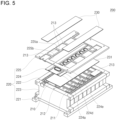
- FIG. 5 is an exploded perspective view of the battery pack 200 according to the other embodiment.
- the battery pack 200 may include a plurality of battery cells 210 and a cover member 220 coupled to the battery cells 210 and covering the outer surfaces of the battery cells 210.
- the battery pack 200 according to the other embodiment may further include heat blocking members 230 on the cover member 220. Components similar to those of the above-described embodiment are denoted by similar reference numerals, and differences therebetween will be mainly described below.
- Each of the battery cells 210 may include electrode terminals 211 on the upper surface thereof and a vent 212 located between the electrode terminals 211. Unlike the previously-described embodiment, both the electrode terminals 211 and the vent 212 are on the upper surface of each of the battery cells 210, for example on predetermined regions on the upper surface.
- the cover member 220 may include a lower cover 221 under the battery cells 210, side covers 222 along the side surfaces of the battery cells 210, end covers 223 coupled to the foremost (frontmost) and rearmost battery cells among the battery cells 210, a reinforcement cover 224 on or over the battery cells 210, and an upper cover 225 on the reinforcement cover 224.
- the lower cover 221 may extend along surfaces of the plurality of arranged battery cells 210, for example, the lower surfaces of the battery cells 210.
- the side covers 222 may be on the lower cover 221 and may be coupled to both side surfaces of the battery cells 210 in the direction in which the battery cells 210 are arranged.
- the end covers 223 may be coupled to the foremost (frontmost) and rearmost battery cells among the battery cells 210, thereby fixing the positions of the battery cells 210 and pressing the foremost (frontmost) and rearmost battery cells among the battery cells 210.
- the reinforcement cover 224 may be coupled to the upper surfaces of the battery cells 210.
- the reinforcement cover 224 may be configured to protect the upper surfaces of the battery cells 210 and to provide mechanical rigidity thereto.
- the reinforcement cover 224 typically does not cover the electrode terminals 211, but may cover the central regions of the upper surfaces of the battery cells 210 in which the vents 212 are formed.
- the width of the reinforcement cover 224 may be smaller than the width of each of the battery cells 210.
- the electrode terminals 211 may be exposed to the outside of the reinforcement cover 224 and may be used for electrical connection using bus bars.
- the reinforcement cover 224 may include open holes formed in regions thereof corresponding to the vents 212 of the battery cells 210. Because the reinforcement cover 224 does not interfere with the vents 212 due to the open holes in the reinforcement cover 224, operation of the vents 212 of the battery cells 210 typically will not be inhibited.
- the reinforcement cover 224 may include a plate portion 224a, two rows of flange portions 224d at the central part of the plate portion 224a and spaced apart from each other in the width direction of the plate portion 224a, and vent protruding portions 224e between the flange portions 224d and located to correspond (e.g., match) the vents 212 of the battery cells 210.
- the flange portions 224d may be arranged in two rows at the central part of the plate portion 224a in order to provide rigidity to the reinforcement cover 224.
- the flange portions 224d may each have a substantially L-shape, like the above-described embodiment.
- the flange portions 224d may be integrally formed with the plate portion 224a by, for example, bending the plate portion 224a so as to protrude in a substantially U-shape.
- the flange portions 224d may have a thickness of about (approximately) 1 mm to about (approximately) 2 mm. If the thickness of the flange portions 224d is equal to or greater than 1 mm, it may be possible to achieve the required rigidity, and if the thickness of the flange portions 224d is equal to or less than 2 mm, it may be suitable for reduction of the overall weight of the battery pack 200.
- the vent protruding portions 224e may be at positions corresponding to the positions of the respective vents 212 of the battery cells 210.
- the vent protruding portions 224e may provide rigidity to the peripheries of the vents 212 of the battery cells 210.
- the vent protruding portions 224e may expose the vents 212 through the open holes formed therein, and thus typically will not disturb or inhibit operation of the vents 212 upon occurrence of an event.
- the vent protruding portions 224e may have a thickness of about (approximately) 1 mm to about (approximately) 2 mm. If the thickness of the vent protruding portions 224e is equal to or greater than 1 mm, it may be possible to achieve the required rigidity, and if the thickness of the vent protruding portions 224e is equal to or less than 2 mm, it may be suitable for reduction of the overall weight of the battery pack 100.
- the heat blocking members 230 may be on or above the reinforcement cover 224.
- the heat blocking members 230 may be coupled to the regions of the upper cover 225 that correspond to the electrode terminals 211 of the battery cells 210 that are exposed to the outside of the reinforcement cover 224.
- the battery pack 200 may further include a heat blocking member 231 between the plurality of battery cells 210 and the reinforcement cover 224 similar to that shown in FIG. 2 .
- the heat blocking members 230 may be placed so as to cover the upper sides of the electrode terminals 211 and the bus bars 213.
- the heat blocking members 230 and 231 may prevent (or at least mitigate) a high-temperature substance generated upon occurrence of an event in any one of the battery cells 210 from scattering to and coming into contact with another battery cell 210 adjacent thereto, thereby blocking (or at least mitigating against) propagation of the event or heat to the other battery cell 210.
- the upper cover 225 may include a plurality of openings 225a arranged at both edges and one opening 225b arranged in the center.
- the bus bars 213 may be located in the openings 225a and may be electrically connected to the terminals of the battery cell 210.
- the heat blocking member 231 and the reinforcement cover 224 may be positioned through the opening 225b and placed on the battery cell 210.
- the rigidity of the reinforcement cover 224 may be achieved by the flange portions 224d arranged in two rows at a central part of the plate portion 224a in the longitudinal direction of the plate portion 224a.
- the vent protruding portions 224e of the reinforcement cover 224 that are located at positions corresponding to the positions of the respective vents 212 of the battery cells 210 may protect the vents 212 and may provide rigidity to the vents 212.
- a battery pack may include a reinforcement cover covering battery cells. Gases generated upon occurrence of an event in a battery cell may move in the longitudinal and width directions of a plate portion of the reinforcement cover through support portions and ventilation portions formed in the longitudinal direction of the plate portion, and the rigidity of the reinforcement cover may be achieved by flange portions arranged in two rows at the central part of the plate portion.
- the reinforcement cover may include vent protruding portions located at positions corresponding to the positions of vents of the battery cells, thereby protecting the vents and providing rigidity to the vents.
Landscapes
- Chemical & Material Sciences (AREA)
- Chemical Kinetics & Catalysis (AREA)
- Electrochemistry (AREA)
- General Chemical & Material Sciences (AREA)
- Engineering & Computer Science (AREA)
- Manufacturing & Machinery (AREA)
- Inorganic Chemistry (AREA)
- Battery Mounting, Suspending (AREA)
Abstract
Description
- Embodiments relate to a battery pack capable of, upon occurrence of a predetermined event in a certain battery cell, reducing propagation of heat to a cell adjacent thereto.
- A secondary battery is a battery that is chargeable and dischargeable, unlike a primary battery that is not rechargeable. A low-capacity secondary battery in which one battery cell is packaged in the form of a pack is used in portable small-sized electronic devices, such as cellular phones and camcorders, and a large-capacity secondary battery in which dozens of battery cells are connected to each other in a battery pack is widely used as power sources for driving motors in hybrid vehicles and the like.
- A secondary battery may include an electrode assembly including a positive electrode plate, a negative electrode plate, and a separator between the positive and negative electrode plates. The electrode assembly and an electrolyte are accommodated in a case, and a cap plate is mounted on the case. The electrode assembly may be a wound electrode assembly or a stacked electrode assembly. In such an electrode assembly, an electrode tab may protrude in an upward or lateral direction, and a current collector may be connected to the electrode tab.
- A secondary battery has recently been applied to high-output products, such as electric vehicles and energy storage systems (ESSs). In order to produce the output required for these products, a plurality of secondary batteries may be provided in the form of a battery pack.
- The information disclosed in this section is provided only for enhancement of understanding of the background of the disclosure and therefore it may contain information that does not form the related art.
- Embodiments provide a battery pack capable of, upon occurrence of a predetermined event in a certain battery cell, reducing propagation of heat to a cell adjacent thereto.
- A battery pack according to an embodiment includes battery cells and a cover member configured to cover the battery cells and including a reinforcement cover on the battery cells. The reinforcement cover includes flange portions arranged in two rows at a central part of the reinforcement cover and extending in the arrangement direction of the battery cells.
- In one or more embodiments, the flange portions may be located at positions corresponding to opposite sides of vents of the battery cells.
- In one or more embodiments, the reinforcement cover may further include a plate portion covering upper surfaces of the battery cells, and the flange portions may have a bent shape and may be coupled to an upper surface of the plate portion.
- In one or more embodiments, the flange portions may include at least one of steel, stainless steel, or aluminum.
- In one or more embodiments, the flange portions may have a thickness in a range from approximately 1 mm to approximately 2 mm.
- In one or more embodiments, the reinforcement cover may further include vent protruding portions between the flange portions and corresponding to the vents of the battery cells.
- In one or more embodiments, the vent protruding portions may protrude upward at positions corresponding to the positions of the vents.
- In one or more embodiments, the vent protruding portions may have a thickness in a range from approximately 1 mm to approximately 2 mm.
- In one or more embodiments, the reinforcement cover may further include support portions on both ends of the reinforcement cover in the width direction of the battery cells and may protrude and be spaced apart from each other in the arrangement direction of the battery cells.
- In one or more embodiments, the reinforcement cover may further include ventilation portions between the support portions that protrude to a height lower than the support portions.
- In one or more embodiments, each of the battery cells may include a terminal provided on a side portion thereof on which the reinforcement cover is not present.
- In one or more embodiments, the battery pack may further include a heat blocking member between the battery cells and the reinforcement cover.
- In one or more embodiments, each of the battery cells may include a terminal provided on an upper side thereof on which the reinforcement cover is present.
- In one or more embodiments, the battery pack may further include a heat blocking member located outside of the reinforcement cover and covering the terminal of each of the battery cells.
- In one or more embodiments, the width of the reinforcement cover may be smaller than the width of each of the plurality of battery cells.
- At least some of the above and other features of the invention are set out in the claims.
- The accompanying drawings, which are incorporated in this specification, illustrate embodiments and serve to further illustrate the technical ideas of the disclosure in conjunction with the detailed description of embodiments that follows, and the disclosure is not to be construed as being limited to what is shown in such drawings. In the drawings:
-
FIG. 1 is a perspective view of a battery pack according to an embodiment; -
FIG. 2 is an exploded perspective view of the battery pack according to the embodiment; -
FIG. 3 is an enlarged view of portion A inFIG. 1 ; -
FIG. 4 is a perspective view of a battery pack according to another embodiment; and -
FIG. 5 is an exploded perspective view of the battery pack according to the other embodiment. - Hereinafter, embodiments will be described in detail with reference to the accompanying drawings.
- Embodiments are provided to more fully illustrate the disclosure to a person having ordinary skill in the art, and the following embodiments may be modified in various other forms, and the scope of the disclosure is not limited to the following embodiments. The embodiments are provided to make the disclosure more faithful and complete and to completely convey the idea of the disclosure fully to those skilled in the art.
- In the following drawings, the thickness or size of each layer is exaggerated for convenience and clarity of description, and same reference symbols in the drawings refer to the same elements. As used herein, the term "and/or" includes any one of the enumerated items and any combination of one or more thereof. As used herein, the term "connected" refers not only to direct connection between members A and B but also to indirect connection between members A and B with member C interposed therebetween.
- The terms used in the specification are intended to describe specific embodiments and are not intended to limit the disclosure. As used herein, singular forms may include plural forms, unless the context clearly indicates otherwise. As used herein, the terms "comprise" (or "include") and/or "comprising" (or "including") are intended to specify the presence of stated figures, numbers, steps, operations, members, elements, and/or groups thereof and do not exclude the presence or addition of one or more other figures, numbers, steps, operations, members, elements, and/or groups thereof. Further, the use of "may" when describing embodiments may refer to "one or more embodiments."
- While terms such as first and second are used herein to describe various members, parts, regions, layers, and/or portions, the members, the parts, the regions, the layers, and/or the portions are not to be limited by the terms. The terms are used only to distinguish one member, one part, one region, one layer, or one portion from another member, another part, another region, another layer, or another portion. Thus, a first member, a first part, a first region, a first layer, or a first portion hereinafter described may refer to a second member, a second part, a second region, a second layer, or a second portion without departing from the teachings of the disclosure.
- Terms related to space, such as "beneath," "below," "lower," "above," and "upper," may be utilized to facilitate understanding of one element or feature shown in the drawings as different from another element or feature. The terms related to space are intended to facilitate understanding of the disclosure in various states of process or use and are not intended to limit the disclosure. For example, if an element or feature in a figure is inverted, an element or feature described as "beneath" or "below" becomes "above" or "upper." Thus, "beneath" is a concept that encompasses "above" or "below."
- A battery pack may include at least one battery module and a pack housing including an accommodation space defined therein to accommodate the at least one battery module.
- The battery module may include a plurality of battery cells and a module housing. The battery cells may be accommodated in the module housing in a stacked form. Each of the battery cells may include a positive electrode lead and a negative electrode lead. The battery cells may be classified as a cylindrical type, a prismatic type, and/or a pouch type, depending on the type of battery.
- Instead of the battery module, one cell stack in which battery cells are stacked may constitute one module in the battery pack. The cell stack may be accommodated in the accommodation space in the pack housing or may be accommodated in an accommodation space defined by a frame, a partition wall, etc.
- The battery cells may generate a large amount of heat during charging/discharging. The generated heat may accumulate in the battery cells and may accelerate deterioration of the battery cells. The battery pack may further include a cooling member in order to suppress deterioration of the battery cells. The cooling member may be disposed on the bottom of the accommodation space in which the battery cells are provided. However, the embodiments are not limited thereto. The cooling member may be disposed on the top or side surface of the accommodation space, depending on the battery pack.
- Gas generated in the battery cells under an abnormal operating condition, also known as thermal runaway or a thermal event, may be discharged outside the battery cells. The battery pack or the battery module may be provided with an exhaust port for discharge of exhaust gas in order to suppress damage thereto due to exhaust gas.
- The battery pack may include a battery and a battery management system (BMS) configured to manage the battery. The battery management system may include a detection device, a balancing device, and a control device.
- The battery module may include a plurality of cells connected to each other in series or in parallel. A plurality of battery modules may be connected to each other in series or in parallel.
- The detection device may detect the state (voltage, current, temperature, etc.) of the battery to obtain state information indicating the state of the battery. The detection device may detect the voltage of each of the cells or each of the battery modules constituting the battery. The detection device may detect the current flowing through each of the battery modules constituting the battery or the battery pack. The detection device may detect the temperature of the cells and/or the modules and/or ambient temperature at at least one point in the battery.
- The balancing device may perform balancing operation on the battery modules and/or the cells constituting the battery.
- The control device may receive the state information indicating the state (voltage, current, temperature, etc.) of the battery modules from the detection device. The control device may monitor and calculate the state (voltage, current, temperature, state of charge (SOC), state of health (SOH), etc.) of the battery modules based on the state information received from the detection device. In some embodiments, the control device may perform a control function (e.g., temperature control, balancing control, charging/discharging control, etc.) and a protection function (e.g., overdischarge prevention, overcharge prevention, overcurrent prevention, short circuit prevention, fire extinguishing, etc.) based on a result of monitoring the state of the battery modules. In some embodiments, the control device may perform a function of executing wired or wireless communication with an external device (e.g., an upper-level controller, a vehicle, a charger, a power conversion system (PCS), etc.) located outside the battery pack.
- The control device may control charging/discharging operation and protection operation of the battery. To this end, the control device may include a charging/discharging controller, a balancing controller, and a protection unit.
- The battery management system may be a system that monitors the state of the battery and performs diagnosis, control, communication, and protection functions. The battery management system may calculate the state of charge/discharge of the battery, may calculate the lifespan or the state of health (SOH) of the battery, may interrupt supply of power from the battery (perform relay control) as needed, may perform thermal management control (cooling, heating, etc.), may perform a high-voltage interlock function, and may detect or calculate insulation and short circuit states.
- The relay may be a mechanical contactor that is turned on or off by a magnetic force of a coil or it may be a semiconductor switch such as a metal oxide semiconductor field effect transistor (MOSFET).
- Relay control may be a function of interrupting supply of power from the battery when a problem occurs in the vehicle and/or the battery system.
- One or more relays and precharge relays may be provided at each of a positive electrode terminal and a negative electrode terminal.
- An in-rush current may be generated in a high-voltage capacitor on an input side of an inverter at the time of connection to the battery load. Precharge control may be a function of performing connection to a precharge resistor by operating the precharge relay before connection of the main relay in order to prevent draw of the in-rush current at the time of startup of the vehicle.
- A high-voltage interlock may be a detection circuit that uses a small signal in order to check whether all high-voltage components are connected to the entire vehicle system. The high-voltage interlock function may be a function of forcibly opening the relay when any one part of the entire loop is in an open state.
- Hereinafter, the configuration of a battery pack according to an embodiment will be described.
-
FIG. 1 is a perspective view of a battery pack according to an embodiment.FIG. 2 is an exploded perspective view of the battery pack according to the embodiment.FIG. 3 is an enlarged view of portion A inFIG. 1 . - Referring to
FIGs. 1 to 3 , thebattery pack 100 according to one embodiment may include a plurality ofbattery cells 110 and acover member 120 coupled to thebattery cells 110 and covering the outer surfaces of thebattery cells 110. In some embodiments, thebattery pack 100 may further include aheat blocking member 130 between thebattery cells 110 and the cover member 120 (seeFigure 2 ). - The plurality of
battery cells 110 may be arranged in one direction as shown. Each of thebattery cells 110 may include an electrode assembly. The electrode assembly may include a first electrode plate, a separator, and a second electrode plate, each of which is formed in a thin plate shape or a membrane shape. The first electrode plate, the separator, and the second electrode plate may be stacked or wound. In some embodiments, the first electrode plate may be a negative electrode, and the second electrode plate may be a positive electrode. In other embodiments, the first electrode plate may be a positive electrode, and the second electrode plate may be a negative electrode. - The first electrode plate may be formed by applying a first electrode active material, such as graphite or carbon, to a first electrode current collector formed as a metal foil made of copper or nickel, and may include a first electrode uncoated portion, which is an area to which the first electrode active material is not applied. The first electrode uncoated portion may provide a passage for the flow of current between the first electrode plate and the outside.
- The second electrode plate may be formed by applying a second electrode active material, such as a transition metal oxide, to a second electrode current collector formed as a metal foil made of aluminum, and may include a second electrode uncoated portion, which is an area to which the second electrode active material is not applied.
- The separator may be between the first electrode plate and the second electrode plate to prevent a short circuit and to enable the movement of lithium ions. The separator may be a film made of polyethylene, polypropylene, or a combination thereof.
- The electrode assembly may be accommodated in a case together with an electrolyte (optional). The electrolyte may include an organic solvent such as ethylene carbonate (EC), propylene carbonate (PC), diethyl carbonate (DEC), ethyl methyl carbonate (EMC), or dimethyl carbonate (DMC) and a lithium salt such as LiPF6 or LiBF4.
- The case may be sealed by a component such as a cap plate or a side plate.
FIG. 1 illustrates an embodiment in which the case is sealed by a side plate, andelectrode terminals 111, which are coupled to the first electrode plate and the second electrode plate, are formed on both sides of the side plate. In one or more embodiments, theelectrode terminals 111 may protrude from both sides (e.g., opposite sides) of the case. - In one or more embodiments, each of the
battery cells 110 may include avent 112 in an upper surface thereof. Thevent 112 may be thinner than the other regions of thebattery cell 110 and thus may be configured to be opened (to rupture) earlier than the other regions of thebattery cell 110 when an internal pressure in thebattery cell 110 is equal to or higher than a reference pressure. Thevent 112 may serve to guide internal gas in thebattery cell 110 to be discharged to the outside in response to the internal pressure in thebattery cell 110 being equal to or higher than the reference pressure, thereby preventing an accident such as an explosion. - In the
battery pack 100, structures such as bus bars may be provided for electrical connection between the battery cells through theelectrode terminals 111 formed on the side portions of the battery cells. In an embodiment in which thevent 112 is in the upper surface of thebattery cell 110, the structures typically will not be affected by opening of thevent 112 of thebattery cell 110. - In one or more embodiments, a spacer may be between every two adjacent ones of the
battery cells 110. The spacer may serve to allow adjacent battery cells to be electrically isolated from each other and to block propagation of heat from one battery cell to another battery cell adjacent thereto. - The
cover member 120 may surround thebattery cells 110 to protect thebattery cells 110 from external impact. Thecover member 120 may include alower cover 121 under thebattery cells 110, side covers 122 along the side surfaces of thebattery cells 110, end covers 123 coupled to the foremost (frontmost) and rearmost battery cells among thebattery cells 110, and areinforcement cover 124 over or on thebattery cells 110. In some embodiments, these covers may be referred to as plates. - The
lower cover 121 may extend along surfaces of the plurality ofbattery cells 110, for example, the lower surfaces of thebattery cells 110. Thelower cover 121 may support loads of thebattery cells 110 and theheat blocking member 130. Thelower cover 121 may also be configured to dissipate heat generated in thebattery cells 110 through the lower surface of thebattery pack 100. - The side covers 122 may be above the
lower cover 121 and may be coupled to both side surfaces of thebattery cells 110 in the direction in which thebattery cells 110 are arranged, thereby fixing the positions of thebattery cells 110. - The
electrode terminals 111 of thebattery cells 110 may be exposed through the side covers 122, and separate bus bars may be coupled to theelectrode terminals 111 to electrically connect thebattery cells 110 to each other. - The end covers 123 may be coupled to the foremost (frontmost) and rearmost battery cells among the
battery cells 110. The end covers 123 may fix the positions of thebattery cells 110 and press the foremost (frontmost) and rearmost battery cells among thebattery cells 110. The end covers 123 may be coupled to thelower cover 121, the side covers 122, and thereinforcement cover 124, and thebattery cells 110 may be accommodated in an internal space defined by thesecovers - The
reinforcement cover 124 may be coupled to the upper surfaces of thebattery cells 110. Thereinforcement cover 124 may protect the upper surfaces of thebattery cells 110 and provide mechanical rigidity thereto. Thereinforcement cover 124 may be made of steel. In other embodiments, thereinforcement cover 124 may be made of stainless steel or aluminum. - The
reinforcement cover 124 may include open holes in regions corresponding to the vents of thebattery cells 110. Because thereinforcement cover 124 does not interfere with the vents due to the open holes in thereinforcement cover 124, operation of the vents of thebattery cells 110 typically will not be inhibited. - In some embodiments, the
reinforcement cover 124 may include aplate portion 124a,support portions 124b on both edges of theplate portion 124a and arranged in the longitudinal direction of theplate portion 124a,ventilation portions 124c on both edges of theplate portion 124a and arranged in the longitudinal direction of theplate portion 124a, two rows offlange portions 124d at the central part of theplate portion 124a and spaced apart from each other in the width direction of theplate portion 124a, and vent protrudingportions 124e between theflange portions 124d and corresponding to thevents 112 of thebattery cells 110. - The
plate portion 124a may have a substantially flat shape and may completely (or substantially completely) cover the upper surfaces of thebattery cells 110. - The
support portions 124b may be on both edges of theplate portion 124a and may be arranged in the longitudinal direction of theplate portion 124a. Thesupport portions 124b may be spaced apart from each other and may protrude farther upward than theplate portion 124a. Theventilation portions 124c may be between thesupport portions 124c along both edges of theplate portion 124a and may protrude farther upward than theplate portion 124a. Theventilation portions 124c may be lower than thesupport portions 124b in order to allow gases generated upon occurrence of an event in thebattery cell 110 to move along theventilation portions 124c on the upper surface of theplate portion 124a. Gas movement passages defined by the ventilation portions 125c may be on the upper surface of theplate portion 124a in the longitudinal direction of theplate portion 124a in the width direction of theplate portion 124a perpendicular to the longitudinal direction thereof, and thus gases may be easily moved and discharged to the outside of thebattery pack 100. - The
flange portions 124d may be arranged in two rows at the central part of theplate portion 124a in order to provide rigidity to thereinforcement cover 124. Theflange portions 124d may be separate components and they may each have, or they may be formed to be bent in, a substantially L-shape. Theflange portions 124d may be coupled to theplate portion 124a. Theflange portions 124d having this L-shape may more reliably provide rigidity to the entirety of thereinforcement cover 124 and may prevent (or at least mitigate) sagging of thereinforcement cover 124. - In one or more embodiments, the
flange portions 124d may have a thickness of about (approximately) 1 mm to about (approximately) 2 mm. If the thickness of theflange portions 124d is equal to or greater than 1 mm, it may be possible to achieve the required rigidity, and if the thickness of theflange portions 124d is equal to or less than 2 mm, it may be suitable for reduction of the overall weight of thebattery pack 100. - The
vent protruding portions 124e may be located at positions corresponding to the positions of therespective vents 112 of thebattery cells 110. Thevent protruding portions 124e may provide rigidity to the peripheries of thevents 112 of thebattery cells 110. Thevent protruding portions 124e may protrude upward along the peripheries of thevents 112, which are formed in the upper surfaces of thebattery cells 110 so as to have a relatively small thickness, thereby protecting thevents 112 from external forces that may be applied to thevents 112. - The
vent protruding portions 124e may expose thevents 112 through the open holes formed therein, and thus will not disturb or inhibit operation of thevents 112 upon the occurrence of an event. - The
vent protruding portions 124e may have a thickness of about (approximately) 1 mm to about (approximately) 2 mm. If the thickness of thevent protruding portions 124e is equal to or greater than 1 mm, it may be possible to achieve the required rigidity, and if the thickness of thevent protruding portions 124e is equal to or less than 2 mm, it may be suitable for reduction of the overall weight of thebattery pack 100. - The
heat blocking member 130 may be between thebattery cells 110 and thereinforcement cover 124. Theheat blocking member 130 may cover the upper surfaces of thebattery cells 110 in which thevents 112 are formed. In an event in which thevent 112 of any one of thebattery cells 110 is opened, a high-temperature substance may be discharged out of the corresponding battery cell. If this high-temperature substance scatters to a neighboringbattery cell 110, for example, onto the vent of a neighboringbattery cell 110, which is vulnerable to heat, thevent 112 of the neighboringbattery cell 110 may be opened. This may result in a problem in which an event occurring in acertain battery cell 110 propagates to anotherbattery cell 110 adjacent thereto. Because theheat blocking member 130 covers the outer sides of the upper surfaces of thebattery cells 110 in which thevents 112 are formed, theheat blocking member 130 may prevent the high-temperature substance scattering from any one of thebattery cells 110 from coming into direct contact with anotherbattery cell 110. In some embodiments, theheat blocking member 130 may be on the outer surfaces of thebattery cells 110 and cover thevents 112 of thebattery cells 110, and thus theheat blocking member 130 may protect thevents 112, which are relatively vulnerable to heat, from the high-temperature scattering substance. - The
heat blocking member 130 may block (or at least mitigate against) the transfer of heat from the high-temperature substance scattering from any one of thebattery cells 110 to anotherbattery cell 110. - The
heat blocking member 130 may be configured to be opened along with the opening of thevent 112 when thevent 112 is operated by the internal pressure in the correspondingbattery cell 110. In this manner, theheat blocking member 130 may protect thebattery cells 110 from the high-temperature scattering substance without disturbing or inhibiting operation of thevents 112. In one or more embodiments, theheat blocking member 130 may be, or may include, for example, a mica sheet. - In some embodiments, the mica sheet may have a thickness of about (approximately) 0.1 mm to about (approximately) 2 mm. If the thickness of the mica sheet is equal to or greater than 0.1 mm, it may be possible to secure required rigidity, and if the thickness of the mica sheet is equal to or less than 2 mm, it may be suitable for reduction of the overall weight of the
battery pack 100. - As described above, in the
battery pack 100 according to one embodiment including thereinforcement cover 124 covering thebattery cells 110, gases generated upon the occurrence of an event in thebattery cell 110 may move in the longitudinal and width directions of theplate portion 124a through thesupport portions 124b and theventilation portions 124c formed in the longitudinal direction of theplate portion 124a, and the rigidity of thereinforcement cover 124 may be secured by theflange portions 124d arranged in two rows at the central part of theplate portion 124a. Thevent protruding portions 124e of thereinforcement cover 124 that are located at positions corresponding to the positions of therespective vents 112 of thebattery cells 110 may protect thevents 112 and may provide rigidity to thevents 112. - Hereinafter, the configuration of a battery pack according to another embodiment will be described.
-
FIG. 4 is a perspective view of abattery pack 200 according to another embodiment.FIG. 5 is an exploded perspective view of thebattery pack 200 according to the other embodiment. - Referring to
FIGs. 4 and5 , thebattery pack 200 according to the other embodiment may include a plurality ofbattery cells 210 and acover member 220 coupled to thebattery cells 210 and covering the outer surfaces of thebattery cells 210. Thebattery pack 200 according to the other embodiment may further includeheat blocking members 230 on thecover member 220. Components similar to those of the above-described embodiment are denoted by similar reference numerals, and differences therebetween will be mainly described below. - Each of the
battery cells 210 may includeelectrode terminals 211 on the upper surface thereof and avent 212 located between theelectrode terminals 211. Unlike the previously-described embodiment, both theelectrode terminals 211 and thevent 212 are on the upper surface of each of thebattery cells 210, for example on predetermined regions on the upper surface. - The
cover member 220 may include alower cover 221 under thebattery cells 210, side covers 222 along the side surfaces of thebattery cells 210, end covers 223 coupled to the foremost (frontmost) and rearmost battery cells among thebattery cells 210, areinforcement cover 224 on or over thebattery cells 210, and anupper cover 225 on thereinforcement cover 224. - In some embodiments, the
lower cover 221 may extend along surfaces of the plurality of arrangedbattery cells 210, for example, the lower surfaces of thebattery cells 210. The side covers 222 may be on thelower cover 221 and may be coupled to both side surfaces of thebattery cells 210 in the direction in which thebattery cells 210 are arranged. The end covers 223 may be coupled to the foremost (frontmost) and rearmost battery cells among thebattery cells 210, thereby fixing the positions of thebattery cells 210 and pressing the foremost (frontmost) and rearmost battery cells among thebattery cells 210. - The
reinforcement cover 224 may be coupled to the upper surfaces of thebattery cells 210. Thereinforcement cover 224 may be configured to protect the upper surfaces of thebattery cells 210 and to provide mechanical rigidity thereto. - The
reinforcement cover 224 typically does not cover theelectrode terminals 211, but may cover the central regions of the upper surfaces of thebattery cells 210 in which thevents 212 are formed. - In some embodiments, the width of the
reinforcement cover 224 may be smaller than the width of each of thebattery cells 210. Thus, theelectrode terminals 211 may be exposed to the outside of thereinforcement cover 224 and may be used for electrical connection using bus bars. - The
reinforcement cover 224 may include open holes formed in regions thereof corresponding to thevents 212 of thebattery cells 210. Because thereinforcement cover 224 does not interfere with thevents 212 due to the open holes in thereinforcement cover 224, operation of thevents 212 of thebattery cells 210 typically will not be inhibited. - In some embodiments, the
reinforcement cover 224 may include aplate portion 224a, two rows offlange portions 224d at the central part of theplate portion 224a and spaced apart from each other in the width direction of theplate portion 224a, and vent protrudingportions 224e between theflange portions 224d and located to correspond (e.g., match) thevents 212 of thebattery cells 210. - The
flange portions 224d may be arranged in two rows at the central part of theplate portion 224a in order to provide rigidity to thereinforcement cover 224. Theflange portions 224d may each have a substantially L-shape, like the above-described embodiment. In other embodiments, theflange portions 224d may be integrally formed with theplate portion 224a by, for example, bending theplate portion 224a so as to protrude in a substantially U-shape. - The
flange portions 224d may have a thickness of about (approximately) 1 mm to about (approximately) 2 mm. If the thickness of theflange portions 224d is equal to or greater than 1 mm, it may be possible to achieve the required rigidity, and if the thickness of theflange portions 224d is equal to or less than 2 mm, it may be suitable for reduction of the overall weight of thebattery pack 200. - The
vent protruding portions 224e may be at positions corresponding to the positions of therespective vents 212 of thebattery cells 210. Thevent protruding portions 224e may provide rigidity to the peripheries of thevents 212 of thebattery cells 210. Thevent protruding portions 224e may expose thevents 212 through the open holes formed therein, and thus typically will not disturb or inhibit operation of thevents 212 upon occurrence of an event. - The
vent protruding portions 224e may have a thickness of about (approximately) 1 mm to about (approximately) 2 mm. If the thickness of thevent protruding portions 224e is equal to or greater than 1 mm, it may be possible to achieve the required rigidity, and if the thickness of thevent protruding portions 224e is equal to or less than 2 mm, it may be suitable for reduction of the overall weight of thebattery pack 100. - The
heat blocking members 230 may be on or above thereinforcement cover 224. Theheat blocking members 230 may be coupled to the regions of theupper cover 225 that correspond to theelectrode terminals 211 of thebattery cells 210 that are exposed to the outside of thereinforcement cover 224. In some embodiments, thebattery pack 200 may further include aheat blocking member 231 between the plurality ofbattery cells 210 and thereinforcement cover 224 similar to that shown inFIG. 2 . - In some embodiments, after bus bars 213 are coupled to the upper sides of the
electrode terminals 211 of thebattery cells 210, theheat blocking members 230 may be placed so as to cover the upper sides of theelectrode terminals 211 and the bus bars 213. Theheat blocking members battery cells 210 from scattering to and coming into contact with anotherbattery cell 210 adjacent thereto, thereby blocking (or at least mitigating against) propagation of the event or heat to theother battery cell 210. - In some embodiments, the
upper cover 225 may include a plurality ofopenings 225a arranged at both edges and oneopening 225b arranged in the center. The bus bars 213 may be located in theopenings 225a and may be electrically connected to the terminals of thebattery cell 210. Theheat blocking member 231 and thereinforcement cover 224 may be positioned through theopening 225b and placed on thebattery cell 210. - As described above, in the
battery pack 200 according to the embodiment ofFigures 4 and5 , including thereinforcement cover 224 covering thebattery cells 210, the rigidity of thereinforcement cover 224 may be achieved by theflange portions 224d arranged in two rows at a central part of theplate portion 224a in the longitudinal direction of theplate portion 224a. Thevent protruding portions 224e of thereinforcement cover 224 that are located at positions corresponding to the positions of therespective vents 212 of thebattery cells 210 may protect thevents 212 and may provide rigidity to thevents 212. - As is apparent from the above description, a battery pack according to an embodiment may include a reinforcement cover covering battery cells. Gases generated upon occurrence of an event in a battery cell may move in the longitudinal and width directions of a plate portion of the reinforcement cover through support portions and ventilation portions formed in the longitudinal direction of the plate portion, and the rigidity of the reinforcement cover may be achieved by flange portions arranged in two rows at the central part of the plate portion.
- The reinforcement cover may include vent protruding portions located at positions corresponding to the positions of vents of the battery cells, thereby protecting the vents and providing rigidity to the vents.
- The above is only one embodiment for implementing a battery pack according to the disclosure, the disclosure is not limited to the above embodiment, and it is to be understood by those skilled in the art that various modifications can be made without departing from the gist of the disclosure as claimed in the following claims.
Claims (15)
- A battery pack comprising:a plurality of battery cells; anda cover member configured to cover the plurality of battery cells, the cover member comprising a reinforcement cover on the plurality of battery cells,wherein the reinforcement cover comprises flange portions arranged in two rows at a central portion of the reinforcement cover and extending in an arrangement direction of the plurality of battery cells.
- The battery pack as claimed in claim 1, wherein the flange portions are located at positions corresponding to opposite sides of vents of the plurality of battery cells.
- The battery pack as claimed in claim 1 or claim 2, wherein the reinforcement cover further comprises a plate portion covering upper surfaces of the plurality of battery cells, and
wherein each of the flange portions has a bent shape and is coupled to an upper surface of the plate portion. - The battery pack as claimed in any one of the preceding claims,
wherein the flange portions comprise at least one of steel, stainless steel, or aluminum. - The battery pack as claimed in any one of the preceding claims,
wherein the flange portions have a thickness in a range from approximately 1 mm to approximately 2 mm. - The battery pack as claimed in any one of the preceding claims,
wherein the reinforcement cover further comprises vent protruding portions between the flange portions and corresponding to vents of the plurality of battery cells. - The battery pack as claimed in claim 6, wherein the vent protruding portions protrude upward at positions corresponding to positions of the vents.
- The battery pack as claimed in claim 6 or claim 7, wherein the vent protruding portions have a thickness in a range from approximately 1 mm to approximately 2 mm.
- The battery pack as claimed in any one of the preceding claims,
wherein the reinforcement cover further comprises support portions on both ends of the reinforcement cover in a width direction of the plurality of battery cells, the support portions being arranged along and spaced apart from each other in the arrangement direction of the plurality of battery cells. - The battery pack as claimed in claim 9, wherein the reinforcement cover further comprises ventilation portions between the support portions, the ventilation portions protruding to a height lower than the support portions.
- The battery pack as claimed in any one of the preceding claims,
wherein each battery cell of the plurality of battery cells comprises a terminal on a side portion of the each battery cell, and wherein the reinforcement cover is not on the side portion. - The battery pack as claimed in any one of the preceding claims,
further comprising a heat blocking member between the plurality of battery cells and the reinforcement cover. - The battery pack as claimed in any one of the preceding claims,
wherein each battery cell of the plurality of battery cells comprises a terminal on an upper side of the each battery cell, and wherein the reinforcement cover is on the upper side of the each battery cell. - The battery pack as claimed in claim 13, further comprising a heat blocking member outside the reinforcement cover and covering the terminal of each battery cell.
- The battery pack as claimed in claim 13 or claim 14, wherein a width of the reinforcement cover is smaller than a width of the each battery cell.
Applications Claiming Priority (1)
| Application Number | Priority Date | Filing Date | Title |
|---|---|---|---|
| KR1020230095339A KR20250014787A (en) | 2023-07-21 | 2023-07-21 | Battery Pack |
Publications (2)
| Publication Number | Publication Date |
|---|---|
| EP4496090A2 true EP4496090A2 (en) | 2025-01-22 |
| EP4496090A3 EP4496090A3 (en) | 2025-02-05 |
Family
ID=91853731
Family Applications (1)
| Application Number | Title | Priority Date | Filing Date |
|---|---|---|---|
| EP24186884.3A Pending EP4496090A3 (en) | 2023-07-21 | 2024-07-05 | Battery pack |
Country Status (4)
| Country | Link |
|---|---|
| US (1) | US20250030109A1 (en) |
| EP (1) | EP4496090A3 (en) |
| KR (1) | KR20250014787A (en) |
| CN (2) | CN119340592A (en) |
Family Cites Families (5)
| Publication number | Priority date | Publication date | Assignee | Title |
|---|---|---|---|---|
| US9263713B2 (en) * | 2010-05-26 | 2016-02-16 | Samsung Sdi Co., Ltd. | Battery pack |
| US8748021B2 (en) * | 2010-10-19 | 2014-06-10 | Samsung Sdi Co., Ltd. | Battery module |
| US9614208B2 (en) * | 2011-10-10 | 2017-04-04 | Samsung Sdi Co., Ltd. | Battery pack with degassing cover and plate thereon |
| KR102152886B1 (en) * | 2017-12-11 | 2020-09-07 | 삼성에스디아이 주식회사 | Battery pack |
| US12300848B2 (en) * | 2019-09-05 | 2025-05-13 | Samsung Sdi Co., Ltd. | Energy storage module including extinguisher sheet |
-
2023
- 2023-07-21 KR KR1020230095339A patent/KR20250014787A/en active Pending
-
2024
- 2024-07-02 US US18/761,925 patent/US20250030109A1/en active Pending
- 2024-07-05 EP EP24186884.3A patent/EP4496090A3/en active Pending
- 2024-07-19 CN CN202410972027.0A patent/CN119340592A/en active Pending
- 2024-07-19 CN CN202421717557.2U patent/CN223006922U/en active Active
Also Published As
| Publication number | Publication date |
|---|---|
| US20250030109A1 (en) | 2025-01-23 |
| CN119340592A (en) | 2025-01-21 |
| CN223006922U (en) | 2025-06-20 |
| EP4496090A3 (en) | 2025-02-05 |
| KR20250014787A (en) | 2025-02-03 |
Similar Documents
| Publication | Publication Date | Title |
|---|---|---|
| KR101447062B1 (en) | Battery Module and Battery Pack Containing the Same | |
| JP5575761B2 (en) | Medium or large battery pack with improved safety | |
| KR20090095525A (en) | Battery module with improved safety and medium and large battery packs including the same | |
| EP4560802A1 (en) | Battery pack | |
| EP4369501A1 (en) | Secondary battery | |
| EP4496090A2 (en) | Battery pack | |
| EP4407755A2 (en) | Battery pack | |
| US20250007042A1 (en) | Battery module | |
| US20250030085A1 (en) | Battery pack | |
| US20250266531A1 (en) | Battery cells and battery modules | |
| US20250329868A1 (en) | Battery module | |
| EP4712210A1 (en) | Battery module | |
| EP4492554A1 (en) | Battery pack | |
| EP4471942A1 (en) | Battery pack | |
| KR20260029055A (en) | Battery cell assembly and battery pack including the same | |
| KR20260017793A (en) | Battery cell assembly and battery pack | |
| CN121970177A (en) | Battery pack and vehicle including the battery pack | |
| KR20240066051A (en) | Secondary Battery | |
| KR20260023722A (en) | Heat dissipation member, battery cell assembly comprising the same, and battery pack comprising the same | |
| KR20260011326A (en) | Cover-cell assembly, battery cell assembly comprising the same and battery pack comprising the same | |
| KR20260044411A (en) | Battery pack | |
| KR20260022675A (en) | Heat dissipation member, battery cell assembly comprising the same, and batter pack comprising the same |
Legal Events
| Date | Code | Title | Description |
|---|---|---|---|
| PUAI | Public reference made under article 153(3) epc to a published international application that has entered the european phase |
Free format text: ORIGINAL CODE: 0009012 |
|
| STAA | Information on the status of an ep patent application or granted ep patent |
Free format text: STATUS: REQUEST FOR EXAMINATION WAS MADE |
|
| PUAL | Search report despatched |
Free format text: ORIGINAL CODE: 0009013 |
|
| 17P | Request for examination filed |
Effective date: 20240705 |
|
| AK | Designated contracting states |
Kind code of ref document: A2 Designated state(s): AL AT BE BG CH CY CZ DE DK EE ES FI FR GB GR HR HU IE IS IT LI LT LU LV MC ME MK MT NL NO PL PT RO RS SE SI SK SM TR |
|
| AK | Designated contracting states |
Kind code of ref document: A3 Designated state(s): AL AT BE BG CH CY CZ DE DK EE ES FI FR GB GR HR HU IE IS IT LI LT LU LV MC ME MK MT NL NO PL PT RO RS SE SI SK SM TR |
|
| RIC1 | Information provided on ipc code assigned before grant |
Ipc: H01M 50/358 20210101ALI20250102BHEP Ipc: H01M 50/273 20210101ALI20250102BHEP Ipc: H01M 50/271 20210101ALI20250102BHEP Ipc: H01M 50/209 20210101AFI20250102BHEP |
|
| STAA | Information on the status of an ep patent application or granted ep patent |
Free format text: STATUS: EXAMINATION IS IN PROGRESS |
|
| 17Q | First examination report despatched |
Effective date: 20250911 |
|
| GRAP | Despatch of communication of intention to grant a patent |
Free format text: ORIGINAL CODE: EPIDOSNIGR1 |
|
| STAA | Information on the status of an ep patent application or granted ep patent |
Free format text: STATUS: GRANT OF PATENT IS INTENDED |
|
| INTG | Intention to grant announced |
Effective date: 20260129 |