EP4495967A1 - Contactor - Google Patents
Contactor Download PDFInfo
- Publication number
- EP4495967A1 EP4495967A1 EP24306098.5A EP24306098A EP4495967A1 EP 4495967 A1 EP4495967 A1 EP 4495967A1 EP 24306098 A EP24306098 A EP 24306098A EP 4495967 A1 EP4495967 A1 EP 4495967A1
- Authority
- EP
- European Patent Office
- Prior art keywords
- housing
- junction box
- wiring
- contactor
- terminal
- Prior art date
- Legal status (The legal status is an assumption and is not a legal conclusion. Google has not performed a legal analysis and makes no representation as to the accuracy of the status listed.)
- Pending
Links
Images

Classifications
-
- H—ELECTRICITY
- H01—ELECTRIC ELEMENTS
- H01H—ELECTRIC SWITCHES; RELAYS; SELECTORS; EMERGENCY PROTECTIVE DEVICES
- H01H9/00—Details of switching devices, not covered by groups H01H1/00 - H01H7/00
- H01H9/02—Bases, casings, or covers
- H01H9/0264—Protective covers for terminals
-
- H—ELECTRICITY
- H01—ELECTRIC ELEMENTS
- H01H—ELECTRIC SWITCHES; RELAYS; SELECTORS; EMERGENCY PROTECTIVE DEVICES
- H01H50/00—Details of electromagnetic relays
- H01H50/14—Terminal arrangements
-
- H—ELECTRICITY
- H01—ELECTRIC ELEMENTS
- H01H—ELECTRIC SWITCHES; RELAYS; SELECTORS; EMERGENCY PROTECTIVE DEVICES
- H01H50/00—Details of electromagnetic relays
- H01H50/02—Bases; Casings; Covers
-
- H—ELECTRICITY
- H01—ELECTRIC ELEMENTS
- H01H—ELECTRIC SWITCHES; RELAYS; SELECTORS; EMERGENCY PROTECTIVE DEVICES
- H01H50/00—Details of electromagnetic relays
- H01H50/54—Contact arrangements
-
- H—ELECTRICITY
- H01—ELECTRIC ELEMENTS
- H01H—ELECTRIC SWITCHES; RELAYS; SELECTORS; EMERGENCY PROTECTIVE DEVICES
- H01H11/00—Apparatus or processes specially adapted for the manufacture of electric switches
- H01H11/0006—Apparatus or processes specially adapted for the manufacture of electric switches for converting electric switches
- H01H11/0031—Apparatus or processes specially adapted for the manufacture of electric switches for converting electric switches for allowing different types or orientation of connections to contacts
- H01H2011/0037—Apparatus or processes specially adapted for the manufacture of electric switches for converting electric switches for allowing different types or orientation of connections to contacts with removable or replaceable terminal blocks
-
- H—ELECTRICITY
- H01—ELECTRIC ELEMENTS
- H01R—ELECTRICALLY-CONDUCTIVE CONNECTIONS; STRUCTURAL ASSOCIATIONS OF A PLURALITY OF MUTUALLY-INSULATED ELECTRICAL CONNECTING ELEMENTS; COUPLING DEVICES; CURRENT COLLECTORS
- H01R4/00—Electrically-conductive connections between two or more conductive members in direct contact, i.e. touching one another; Means for effecting or maintaining such contact; Electrically-conductive connections having two or more spaced connecting locations for conductors and using contact members penetrating insulation
- H01R4/10—Electrically-conductive connections between two or more conductive members in direct contact, i.e. touching one another; Means for effecting or maintaining such contact; Electrically-conductive connections having two or more spaced connecting locations for conductors and using contact members penetrating insulation effected solely by twisting, wrapping, bending, crimping, or other permanent deformation
- H01R4/18—Electrically-conductive connections between two or more conductive members in direct contact, i.e. touching one another; Means for effecting or maintaining such contact; Electrically-conductive connections having two or more spaced connecting locations for conductors and using contact members penetrating insulation effected solely by twisting, wrapping, bending, crimping, or other permanent deformation by crimping
-
- H—ELECTRICITY
- H01—ELECTRIC ELEMENTS
- H01R—ELECTRICALLY-CONDUCTIVE CONNECTIONS; STRUCTURAL ASSOCIATIONS OF A PLURALITY OF MUTUALLY-INSULATED ELECTRICAL CONNECTING ELEMENTS; COUPLING DEVICES; CURRENT COLLECTORS
- H01R4/00—Electrically-conductive connections between two or more conductive members in direct contact, i.e. touching one another; Means for effecting or maintaining such contact; Electrically-conductive connections having two or more spaced connecting locations for conductors and using contact members penetrating insulation
- H01R4/28—Clamped connections, spring connections
- H01R4/30—Clamped connections, spring connections utilising a screw or nut clamping member
- H01R4/34—Conductive members located under head of screw
-
- H—ELECTRICITY
- H02—GENERATION; CONVERSION OR DISTRIBUTION OF ELECTRIC POWER
- H02G—INSTALLATION OF ELECTRIC CABLES OR LINES, OR OF COMBINED OPTICAL AND ELECTRIC CABLES OR LINES
- H02G3/00—Installations of electric cables or lines or protective tubing therefor in or on buildings, equivalent structures or vehicles
- H02G3/02—Details
- H02G3/08—Distribution boxes; Connection or junction boxes
Definitions
- the present disclosure relates to a contactor.
- Contactors are widely used. There are many connection modes between contactor and wires. When facing different connection methods with different demands, it is usually necessary to design different contactor interfaces, which leads to an increase in design cost, manufacturing cost, and management cost.
- a contactor in view of the above problems, according to a first aspect of the present disclosure, includes a housing; a plurality of stationary contact brackets, fixed to the housing, wherein each of the plurality of stationary contact brackets includes a bracket body accommodated in the housing and a wiring terminal extending out of the housing and configured to be connected with an electric wire, the wiring terminal includes a sheet-shaped terminal body and a terminal hole penetrating through a thickness of the terminal body; and an isolation sheet, arranged between adjacent wiring terminals and separates the adjacent wiring terminals.
- the design of the contactor according to the present disclosure can meet at least four different connection modes of different customers at the same time, thus increasing the application compatibility of the contactor and reducing the design cost and management cost.
- the contactor according to the present disclosure can have one or more of the following features.
- the isolation sheet is insulated and detachably assembled to the housing.
- the contactor includes a junction box detachably assembled to the housing, and the junction box includes: a plurality of wiring holes, each of the plurality of wiring holes being configured to accommodate a corresponding wiring terminal upon the junction box being assembled to the housing; and an isolation sheet avoidance hole arranged between adjacent wiring holes and configured to allow the isolation sheet to pass through upon the junction box being assembled to the housing.
- a surface of the junction box facing the housing includes a first installation feature
- a surface of the housing facing the junction box includes a second installation feature
- the first installation feature and the second installation feature cooperate with each other to assemble the junction box to the housing.
- the first installation feature is a mounting boss and the second installation feature is a mounting groove.
- the junction box further includes: an upper crimping piece positioned above the wiring terminal; a lower crimping piece positioned below the wiring terminal; and an actuating piece configured to simultaneously drive the upper crimping piece to move downward and the lower crimping piece to move upward toward the wiring terminal upon being driven.
- At least one of the upper crimping piece and the lower crimping piece is a deformable elastic piece.
- the junction box includes an upper elastic element that biases the upper crimping piece downward, and/or the junction box includes a lower elastic element that biases the lower crimping piece upward.
- the junction box further includes: a bolt including a bolt post configured to pass through the terminal hole of a corresponding wiring terminal and a bolt head with a diameter being lager than a diameter of the bolt post; a washer arranged between the wiring terminal and the bolt head, an outer diameter of the washer is larger than the diameter of the bolt head, and a diameter of a center hole of the washer is smaller than the diameter of the bolt head and allows the bolt post to pass through; a nut fixed to a box body of the junction box below the wiring terminal; and an upper passage extending upward from a position of the wiring terminal, thereby allowing a tool to extend downward through the upper passage from outside and tighten the bolt to the nut, so that the washer is pressed against the wiring terminal.
- the contactor includes a first group of wiring terminals protruding out of the housing in a first direction and a second group of wiring terminals protruding out of the housing in a second direction opposite to the first direction.
- the contactor includes three stationary contact brackets and four isolation sheets, two of the four isolation sheets are respectively arranged between adjacent wiring terminals of the first group of wiring terminals and other two of the four isolation sheets are respectively arranged between adjacent wiring terminals of the second group of wiring terminals.
- the interface design of the contactor according to the present disclosure is suitable for various connection modes.
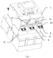
- the contactor according to the present disclosure includes a housing 1, and the housing 1 is configured to accommodate components of the contactor.
- the contactor according to the present disclosure also includes a plurality of stationary contact brackets, for example, in the embodiment of Fig. 1 , the contactor includes three stationary contact brackets.
- the plurality of stationary contact brackets are fixed to the housing 1, and each of the plurality of stationary contact brackets includes a bracket body accommodated in the housing 1 and a wiring terminal 2 extending out of the housing 1 and configured to be connected with an electric wire.
- the wiring terminal 2 includes a sheet-shaped terminal body and a terminal hole 21 penetrating through the terminal body in a thickness direction.
- Each of the plurality of stationary contact brackets includes a first wiring terminal protruding out of the housing 1 in a first direction and a second wiring terminal protruding out of the housing 1 in a second direction opposite to the first direction, so that after the first wiring terminal and the second wiring terminal are connected with external wires, a closed loop that can be broken by the contactor can be formed.
- the first wiring terminals of the three stationary contact brackets constitute a first group of wiring terminals
- the second wiring terminals of the three stationary contact brackets constitute a second group of wiring terminals.
- the contactor according to the present disclosure further includes an isolation sheet 3, the isolation sheet 3 is arranged between adjacent wiring terminals 2 and separates the adjacent wiring terminals 2.
- the contactor includes four isolation sheets 3, two of the four isolation sheets 3 are respectively arranged between adjacent wiring terminals 2 of the first group of wiring terminals, and the other two of the four isolation sheets 3 are respectively arranged between adjacent wiring terminals 2 of the second group of wiring terminals.
- the isolation sheet 3 is insulated.
- the isolation sheet 3 is detachably assembled to the housing 1. Due to the existence of the isolation sheet 3, the contactor according to the present disclosure can be directly connected with a bare copper bar or a wire with lug. Due to the above-mentioned structure of the contactor according to the present disclosure, the contactor can also be connected with a junction box 4, and can be suitable for different types of junction boxes 4. The structures of different types of junction boxes 4 are described in detail as follows.
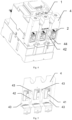
- Fig. 2 is a perspective view of a contactor assembled with a first junction box 4 according to the present disclosure.
- Fig. 3 is a perspective view of a first junction box 4 according to the present disclosure.
- the first junction box 4 is detachably assembled to the housing 1 of the contactor.
- the first junction box 4 and the housing 1 may include complementary installation features, respectively.
- a surface of the first junction box 4 facing the housing 1 may include a first installation feature
- the surface of the housing 1 facing the first junction box 4 may include a second installation feature, which cooperate with each other to assemble the first junction box 4 to the housing 1.
- a surface of the first junction box 4 facing the housing 1 may include a first installation feature
- the surface of the housing 1 facing the first junction box 4 may include a second installation feature, which cooperate with each other to assemble the first junction box 4 to the housing 1.
- the surface of the housing 1 facing the first junction box 4 includes four mounting grooves 11
- the surface of the first junction box 4 facing the housing 1 includes four mounting bosses 43
- the positions of the mounting grooves 11 and the mounting bosses 43 are corresponding, so that when it is needed to assemble the first junction box 4 to the housing 1, it is only needed to align the corresponding installation features and snap fit them in place, for example.
- the first junction box 4 and the housing 1 can be assembled in other ways, and the installation features can be arranged at other positions different from those shown in the figure, or even on other surfaces of the housing 1.
- the first junction box 4 includes a plurality of wiring holes 41, and the wiring holes 41 accommodate the corresponding wiring terminals 2 when the first junction box 4 is assembled to the housing 1.
- the first junction box 4 includes three connection holes 41, each of the three connection holes 41 allows the corresponding wiring terminal 2 to extend into it.
- the electric wire can extend into the wiring hole 41 from a side of the first junction box 4 away from the housing 1 and be connected with the wiring terminal 2.
- each of the wiring holes 41 includes two openings on the side of the first junction box 4 away from the housing 1, the upper opening is located above the wiring terminal 2 and the lower opening is located below the wiring terminal 2, so that the electric wire can extend into the wiring hole 41 from the upper opening and/or the lower opening and be connected with the wiring terminal 2.
- the first junction box 4 may further include an upper crimping piece positioned above the wiring terminal 2; a lower crimping piece 44 positioned below the wiring terminal 2; and an actuating member, which can be driven by the user, and thus simultaneously drives the upper crimping piece to move downward and the lower crimping piece 44 to move upward toward the wiring terminal 2, thereby tightly crimping the electric wire with the wiring terminal 2.
- the first junction box 4 further includes an isolation sheet avoidance hole 42, as illustrated by Fig. 3 , the isolation sheet avoidance hole 42 is arranged between adjacent wiring holes 41 and configured to allow the isolation sheet 3 to pass through when the first junction box 4 is assembled to the housing 1.
- the isolation sheet avoidance hole 42 is arranged between adjacent wiring holes 41 and configured to allow the isolation sheet 3 to pass through when the first junction box 4 is assembled to the housing 1.
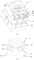
- Fig. 4 is a perspective view of a contactor assembled with a second junction box 4 according to the present disclosure.
- Fig. 5 is a perspective view of a second junction box 4 according to the present disclosure.
- the second junction box 4 has a similar structure to the first junction box 4, and only the differences from the first junction box 4 will be described below.
- the second junction box 4 is added with an elastic compensation function, that is, when the connected electric wire has a loosening trend, this part of the loosening gap can be compensated.
- at least one of the upper crimping piece and the lower crimping piece 44 of the second junction box 4 may be a deformable elastic piece. In the embodiment shown in Figs.
- the lower crimping piece 44 of the second junction box 4 is an elastic piece.
- the second junction box 4 may include an upper elastic element that biases the upper crimping piece downward; and/or the junction box 4 may include a lower elastic element that biases the lower crimping piece 44 upward, thereby achieving a similar elastic compensation function.
- Fig. 6 is a perspective view of a contactor assembled with a third junction box 4 according to the present disclosure.
- Fig. 7 is a perspective view of a third junction box 4 according to the present disclosure.
- the third junction box 4 includes installation features, isolation sheet avoidance holes 42, and wiring holes 41 which are similar to those of the first junction box 4, so that the third junction box 4 can also be adapted to the housing 1 of Fig. 1 , so that the third junction box 4 can be assembled to the housing 1.
- the main difference between the third junction box 4 and the first junction box 4 is that, instead of the upper crimping piece and the lower crimping piece, the third junction box 4 uses a bolt 45 and a nut to press the electric wire (or copper bar) and the wiring terminal 2. Specifically, as illustrated by Fig.
- the third junction box 4 may include a bolt 45 including a bolt post configured to pass through the terminal hole 21 of a corresponding wiring terminal 2 and a bolt head with a diameter being larger than the bolt post; a washer 46, arranged between the wiring terminal 2 and the bolt head, an outer diameter of the washer 46 is larger than the diameter of the bolt head, and a diameter of a center hole of the washer 46 is smaller than the diameter of the bolt head and allows the bolt to pass through; a nut, fixed to a box body of the junction box 4 below the wiring terminal 2; and an upper passage extending upward from a position of the wiring terminal 2, thereby allowing a tool to extend downward through the upper passage from the outside and tighten the bolt 45 to the nut, so that the washer 46 is pressed against the wiring terminal 2.
- the contactor according to the present disclosure can be applied to at least the following four connection modes:
- the design of a contactor can meet at least four different connection modes of different customers at the same time, the application compatibility of the contactor is increased and the design cost and management cost are reduced.
Landscapes
- Physics & Mathematics (AREA)
- Electromagnetism (AREA)
- Connection Or Junction Boxes (AREA)
Abstract
A contactor, which includes: a housing; a plurality of stationary contact brackets, fixed to the housing, wherein each of the plurality of stationary contact brackets includes a bracket body accommodated in the housing and a wiring terminal extending out of the housing and configured to be connected with an electric wire, the wiring terminal includes a sheet-shaped terminal body and a terminal hole penetrating through a thickness of the terminal body; and an isolation sheet, arranged between adjacent wiring terminals and separates the adjacent wiring terminals. The design of the contactor according to the present disclosure can meet at least four different connection modes of different customers at the same time, thus increasing the application compatibility of the contactor and reducing the design cost and management cost.
Description
- The present disclosure relates to a contactor.
- Contactors are widely used. There are many connection modes between contactor and wires. When facing different connection methods with different demands, it is usually necessary to design different contactor interfaces, which leads to an increase in design cost, manufacturing cost, and management cost.
- In view of the above problems, according to a first aspect of the present disclosure, a contactor is provided, the contactor includes a housing; a plurality of stationary contact brackets, fixed to the housing, wherein each of the plurality of stationary contact brackets includes a bracket body accommodated in the housing and a wiring terminal extending out of the housing and configured to be connected with an electric wire, the wiring terminal includes a sheet-shaped terminal body and a terminal hole penetrating through a thickness of the terminal body; and an isolation sheet, arranged between adjacent wiring terminals and separates the adjacent wiring terminals.
- The design of the contactor according to the present disclosure can meet at least four different connection modes of different customers at the same time, thus increasing the application compatibility of the contactor and reducing the design cost and management cost.
- The contactor according to the present disclosure can have one or more of the following features.
- According to an embodiment, the isolation sheet is insulated and detachably assembled to the housing.
- According to an embodiment, the contactor includes a junction box detachably assembled to the housing, and the junction box includes: a plurality of wiring holes, each of the plurality of wiring holes being configured to accommodate a corresponding wiring terminal upon the junction box being assembled to the housing; and an isolation sheet avoidance hole arranged between adjacent wiring holes and configured to allow the isolation sheet to pass through upon the junction box being assembled to the housing.
- According to an embodiment, a surface of the junction box facing the housing includes a first installation feature, and a surface of the housing facing the junction box includes a second installation feature, the first installation feature and the second installation feature cooperate with each other to assemble the junction box to the housing.
- According to an embodiment, the first installation feature is a mounting boss and the second installation feature is a mounting groove.
- According to an embodiment, the junction box further includes: an upper crimping piece positioned above the wiring terminal; a lower crimping piece positioned below the wiring terminal; and an actuating piece configured to simultaneously drive the upper crimping piece to move downward and the lower crimping piece to move upward toward the wiring terminal upon being driven.
- According to an embodiment, at least one of the upper crimping piece and the lower crimping piece is a deformable elastic piece.
- According to an embodiment, the junction box includes an upper elastic element that biases the upper crimping piece downward, and/or the junction box includes a lower elastic element that biases the lower crimping piece upward.
- According to an embodiment, the junction box further includes: a bolt including a bolt post configured to pass through the terminal hole of a corresponding wiring terminal and a bolt head with a diameter being lager than a diameter of the bolt post; a washer arranged between the wiring terminal and the bolt head, an outer diameter of the washer is larger than the diameter of the bolt head, and a diameter of a center hole of the washer is smaller than the diameter of the bolt head and allows the bolt post to pass through; a nut fixed to a box body of the junction box below the wiring terminal; and an upper passage extending upward from a position of the wiring terminal, thereby allowing a tool to extend downward through the upper passage from outside and tighten the bolt to the nut, so that the washer is pressed against the wiring terminal.
- According to an embodiment, the contactor includes a first group of wiring terminals protruding out of the housing in a first direction and a second group of wiring terminals protruding out of the housing in a second direction opposite to the first direction.
- According to an embodiment, the contactor includes three stationary contact brackets and four isolation sheets, two of the four isolation sheets are respectively arranged between adjacent wiring terminals of the first group of wiring terminals and other two of the four isolation sheets are respectively arranged between adjacent wiring terminals of the second group of wiring terminals.
- In order to illustrate the technical solution of the present disclosure clearer, the accompanying drawings of the present disclosure will be described briefly in the following. The accompanying drawings described here are only for illustrative purposes of some embodiments, and are not intended to limit all embodiments of the present disclosure.
-
Fig. 1 is a perspective view of a contactor according to the present disclosure. -
Fig. 2 is a perspective view of a contactor assembled with a first junction box according to the present disclosure. -
Fig. 3 is a perspective view of a first junction box according to the present disclosure. -
Fig. 4 is a perspective view of a contactor assembled with a second junction box according to the present disclosure. -
Fig. 5 is a perspective view of a second junction box according to the present disclosure. -
Fig. 6 is a perspective view of a contactor assembled with a third junction box according to the present disclosure. -
Fig. 7 is a perspective view of a third junction box according to the present disclosure. - List of reference numerals:
- 1-housing
- 11 -installation slot
- 2-wiring terminal
- 21-terminal hole
- 3-isolation sheet
- 4junction box
- 41-wiring hole
- 42-isolation sheet avoidance hole
- 43-mounting boss
- 44-lower crimping piece
- 45-bolt
- 46-washer
- In order to make the purpose, technical solution and advantages of the technical solution of the present disclosure clearer, the technical solution of the embodiments of the present disclosure will be described clearly and completely with the attached drawings of the specific embodiment of the present disclosure. Like reference numerals in the drawings represent like parts. It should be noted that the described embodiment is a part of the embodiment of the present disclosure, not the whole embodiments. Based on the described embodiment of the present disclosure, all other embodiments obtained by ordinary skilled in the art without creative labor belong to the protection scope of the present disclosure.
- Unless otherwise defined, technical terms or scientific terms used here shall have their ordinary meanings as understood by people with ordinary skills in the field to which this present disclosure belongs. The "first", "second" and similar words used in the specification and claims of the present disclosure patent application do not indicate any order, quantity or importance, but are only used to distinguish different components. Similar words such as "including" or "containing" mean that the elements or objects appearing before the word cover the elements or objects listed after the word and their equivalents, without excluding other elements or objects. Similar words such as "connected" or "connected" are not limited to physical or mechanical connection, but can include electrical connection, whether direct or indirect. "Up", "Down", "Left" and "Right" are only used to indicate the relative positional relationship. When the absolute position of the described object changes, the relative positional relationship may also change accordingly.
- Hereinafter, the present disclosure will be described in detail by describing the example embodiments.
- In order to meet the requirements of different customers for different connection modes, the interface design of the contactor according to the present disclosure is suitable for various connection modes. Specifically, as illustrated by
Fig. 1 , the contactor according to the present disclosure includes ahousing 1, and thehousing 1 is configured to accommodate components of the contactor. The contactor according to the present disclosure also includes a plurality of stationary contact brackets, for example, in the embodiment ofFig. 1 , the contactor includes three stationary contact brackets. The plurality of stationary contact brackets are fixed to thehousing 1, and each of the plurality of stationary contact brackets includes a bracket body accommodated in thehousing 1 and awiring terminal 2 extending out of thehousing 1 and configured to be connected with an electric wire. As illustrated byFig. 1 , thewiring terminal 2 includes a sheet-shaped terminal body and aterminal hole 21 penetrating through the terminal body in a thickness direction. Each of the plurality of stationary contact brackets includes a first wiring terminal protruding out of thehousing 1 in a first direction and a second wiring terminal protruding out of thehousing 1 in a second direction opposite to the first direction, so that after the first wiring terminal and the second wiring terminal are connected with external wires, a closed loop that can be broken by the contactor can be formed. In the embodiment ofFig. 1 , the first wiring terminals of the three stationary contact brackets constitute a first group of wiring terminals, and the second wiring terminals of the three stationary contact brackets constitute a second group of wiring terminals. The contactor according to the present disclosure further includes anisolation sheet 3, theisolation sheet 3 is arranged betweenadjacent wiring terminals 2 and separates theadjacent wiring terminals 2. In the embodiment ofFig. 1 , the contactor includes fourisolation sheets 3, two of the fourisolation sheets 3 are respectively arranged betweenadjacent wiring terminals 2 of the first group of wiring terminals, and the other two of the fourisolation sheets 3 are respectively arranged betweenadjacent wiring terminals 2 of the second group of wiring terminals. Theisolation sheet 3 is insulated. Optionally, theisolation sheet 3 is detachably assembled to thehousing 1. Due to the existence of theisolation sheet 3, the contactor according to the present disclosure can be directly connected with a bare copper bar or a wire with lug. Due to the above-mentioned structure of the contactor according to the present disclosure, the contactor can also be connected with ajunction box 4, and can be suitable for different types ofjunction boxes 4. The structures of different types ofjunction boxes 4 are described in detail as follows. -
Fig. 2 is a perspective view of a contactor assembled with afirst junction box 4 according to the present disclosure.Fig. 3 is a perspective view of afirst junction box 4 according to the present disclosure. Referring toFigs. 2 and 3 , thefirst junction box 4 is detachably assembled to thehousing 1 of the contactor. In order to achieve detachable assembly, thefirst junction box 4 and thehousing 1 may include complementary installation features, respectively. As one embodiment, a surface of thefirst junction box 4 facing thehousing 1 may include a first installation feature, and the surface of thehousing 1 facing thefirst junction box 4 may include a second installation feature, which cooperate with each other to assemble thefirst junction box 4 to thehousing 1. Specifically, in the embodiment shown inFigs. 1 and3 , the surface of thehousing 1 facing thefirst junction box 4 includes four mountinggrooves 11, the surface of thefirst junction box 4 facing thehousing 1 includes four mountingbosses 43, and the positions of the mountinggrooves 11 and the mountingbosses 43 are corresponding, so that when it is needed to assemble thefirst junction box 4 to thehousing 1, it is only needed to align the corresponding installation features and snap fit them in place, for example. It should be noted that thefirst junction box 4 and thehousing 1 can be assembled in other ways, and the installation features can be arranged at other positions different from those shown in the figure, or even on other surfaces of thehousing 1. - In order to realize wiring in the
first junction box 4, thefirst junction box 4 includes a plurality of wiring holes 41, and the wiring holes 41 accommodate thecorresponding wiring terminals 2 when thefirst junction box 4 is assembled to thehousing 1. As illustrated by the embodiment ofFig. 3 , thefirst junction box 4 includes threeconnection holes 41, each of the threeconnection holes 41 allows the correspondingwiring terminal 2 to extend into it. The electric wire can extend into thewiring hole 41 from a side of thefirst junction box 4 away from thehousing 1 and be connected with thewiring terminal 2. In the embodiment ofFig. 2 , each of the wiring holes 41 includes two openings on the side of thefirst junction box 4 away from thehousing 1, the upper opening is located above thewiring terminal 2 and the lower opening is located below thewiring terminal 2, so that the electric wire can extend into thewiring hole 41 from the upper opening and/or the lower opening and be connected with thewiring terminal 2. Thefirst junction box 4 may further include an upper crimping piece positioned above thewiring terminal 2; a lower crimpingpiece 44 positioned below thewiring terminal 2; and an actuating member, which can be driven by the user, and thus simultaneously drives the upper crimping piece to move downward and the lower crimpingpiece 44 to move upward toward thewiring terminal 2, thereby tightly crimping the electric wire with thewiring terminal 2. - The
first junction box 4 further includes an isolationsheet avoidance hole 42, as illustrated byFig. 3 , the isolationsheet avoidance hole 42 is arranged between adjacent wiring holes 41 and configured to allow theisolation sheet 3 to pass through when thefirst junction box 4 is assembled to thehousing 1. Through the design of thefirst junction box 4, the interference between thefirst junction box 4 and theisolation sheet 3 is avoided, and thefirst junction box 4 can be directly assembled without disassembling theisolation sheet 3, so that the contactor according to the present disclosure can be suitable for different connection modes and can be conveniently switched between different connection modes. -
Fig. 4 is a perspective view of a contactor assembled with asecond junction box 4 according to the present disclosure.Fig. 5 is a perspective view of asecond junction box 4 according to the present disclosure. Referring toFigs. 4 and 5 , thesecond junction box 4 has a similar structure to thefirst junction box 4, and only the differences from thefirst junction box 4 will be described below. Compared with thefirst junction box 4, thesecond junction box 4 is added with an elastic compensation function, that is, when the connected electric wire has a loosening trend, this part of the loosening gap can be compensated. Specifically, at least one of the upper crimping piece and the lower crimpingpiece 44 of thesecond junction box 4 may be a deformable elastic piece. In the embodiment shown inFigs. 4 and 5 , the lower crimpingpiece 44 of thesecond junction box 4 is an elastic piece. When wiring, the lower crimpingpiece 44 is compressed to store energy; when the connected electric wire has a loosening trend, the lower crimpingpiece 44 releases energy and rebounds, and continues to press the electric wire to thewiring terminal 2. Alternatively, in another embodiment not shown, thesecond junction box 4 may include an upper elastic element that biases the upper crimping piece downward; and/or thejunction box 4 may include a lower elastic element that biases the lower crimpingpiece 44 upward, thereby achieving a similar elastic compensation function. -
Fig. 6 is a perspective view of a contactor assembled with athird junction box 4 according to the present disclosure.Fig. 7 is a perspective view of athird junction box 4 according to the present disclosure. Referring toFigs. 6 and 7 , thethird junction box 4 includes installation features, isolation sheet avoidance holes 42, and wiring holes 41 which are similar to those of thefirst junction box 4, so that thethird junction box 4 can also be adapted to thehousing 1 ofFig. 1 , so that thethird junction box 4 can be assembled to thehousing 1. The main difference between thethird junction box 4 and thefirst junction box 4 is that, instead of the upper crimping piece and the lower crimping piece, thethird junction box 4 uses abolt 45 and a nut to press the electric wire (or copper bar) and thewiring terminal 2. Specifically, as illustrated byFig. 6 , thethird junction box 4 may include abolt 45 including a bolt post configured to pass through theterminal hole 21 of acorresponding wiring terminal 2 and a bolt head with a diameter being larger than the bolt post; awasher 46, arranged between thewiring terminal 2 and the bolt head, an outer diameter of thewasher 46 is larger than the diameter of the bolt head, and a diameter of a center hole of thewasher 46 is smaller than the diameter of the bolt head and allows the bolt to pass through; a nut, fixed to a box body of thejunction box 4 below thewiring terminal 2; and an upper passage extending upward from a position of thewiring terminal 2, thereby allowing a tool to extend downward through the upper passage from the outside and tighten thebolt 45 to the nut, so that thewasher 46 is pressed against thewiring terminal 2. - To sum up, the contactor according to the present disclosure can be applied to at least the following four connection modes:
- 1) Direct connection with a bare copper bar or a wire with lug;
- 2) A junction box for realizing crimping by an upper crimping piece and a lower crimping piece approaching to the wiring terminal;
- 3) A junction box with elastic compensation function, which realizes crimping by an upper crimping piece and a lower crimping piece approaching to the wiring terminal;
- 4) A junction box for realizing crimping by a tightening fit of a bolt and a nut to tighten.
- Because the design of a contactor can meet at least four different connection modes of different customers at the same time, the application compatibility of the contactor is increased and the design cost and management cost are reduced.
- The exemplary implementation of the contactor proposed by the present disclosure has been described in detail above with reference to the preferred embodiment. However, it can be understood by those skilled in the art that various variations and modifications can be made to the above specific embodiment without departing from the concept of the present disclosure, and various technical features and structures proposed by the present disclosure can be combined in various ways without exceeding the protection scope of this present disclosure.
Claims (11)
- A contactor, comprising:a housing;a plurality of stationary contact brackets fixed to the housing, wherein each of the plurality of stationary contact brackets comprises a bracket body accommodated in the housing and a wiring terminal extending out of the housing and configured to be connected with an electric wire, the wiring terminal comprises a sheet-shaped terminal body and a terminal hole penetrating through a thickness of the terminal body; andan isolation sheet, arranged between adjacent wiring terminals and separates the adjacent wiring terminals.
- The contactor according to claim 1, wherein the isolation sheet is insulated and detachably assembled to the housing.
- The contactor according to claim 1 or 2, wherein the contactor comprises a junction box detachably assembled to the housing, and the junction box comprises:a plurality of wiring holes, each of the plurality of wiring holes being configured to accommodate a corresponding wiring terminal upon the junction box being assembled to the housing; andan isolation sheet avoidance hole, arranged between adjacent wiring holes and configured to allow the isolation sheet to pass through upon the junction box being assembled to the housing.
- The contactor according to claim 3, wherein a surface of the junction box facing the housing comprises a first installation feature, and a surface of the housing facing the junction box comprises a second installation feature, the first installation feature and the second installation feature cooperate with each other to assemble the junction box to the housing.
- The contactor according to claim 4, wherein the first installation feature is a mounting boss and the second installation feature is a mounting groove.
- The contactor according to claim 3, wherein the junction box further comprises:an upper crimping piece positioned above the wiring terminal;a lower crimping piece positioned below the wiring terminal; andan actuating piece configured to simultaneously drive the upper crimping piece to move downward and the lower crimping piece to move upward toward the wiring terminal upon being driven.
- The contactor according to claim 6, wherein at least one of the upper crimping piece and the lower crimping piece is a deformable elastic piece.
- The contactor according to claim 6, wherein the junction box comprises an upper elastic element that biases the upper crimping piece downward,
and/or the junction box comprises a lower elastic element that biases the lower crimping piece upward. - The contactor according to claim 3, wherein the junction box further comprises:a bolt comprising a bolt post configured to pass through the terminal hole of a corresponding wiring terminal and a bolt head with a diameter being lager than a diameter of the bolt post;a washer arranged between the wiring terminal and the bolt head, an outer diameter of the washer is larger than the diameter of the bolt head, and a diameter of a center hole of the washer is smaller than the diameter of the bolt head and allows the bolt post to pass through;a nut fixed to a box body of the junction box below the wiring terminal; andan upper passage extending upward from a position of the wiring terminal, thereby allowing a tool to extend downward through the upper passage from outside and tighten the bolt to the nut, so that the washer is pressed against the wiring terminal.
- The contactor according to claim 1 or 2, wherein the contactor comprises a first group of wiring terminals protruding out of the housing in a first direction and a second group of wiring terminals protruding out of the housing in a second direction opposite to the first direction.
- The contactor according to claim 10, wherein the contactor comprises three stationary contact brackets and four isolation sheets, two of the four isolation sheets are respectively arranged between adjacent wiring terminals of the first group of wiring terminals and the other two of the four isolation sheets are respectively arranged between adjacent wiring terminals of the second group of wiring terminals.
Applications Claiming Priority (1)
| Application Number | Priority Date | Filing Date | Title |
|---|---|---|---|
| CN202321915628.5U CN220382010U (en) | 2023-07-19 | 2023-07-19 | contactor |
Publications (1)
| Publication Number | Publication Date |
|---|---|
| EP4495967A1 true EP4495967A1 (en) | 2025-01-22 |
Family
ID=89563952
Family Applications (1)
| Application Number | Title | Priority Date | Filing Date |
|---|---|---|---|
| EP24306098.5A Pending EP4495967A1 (en) | 2023-07-19 | 2024-07-03 | Contactor |
Country Status (3)
| Country | Link |
|---|---|
| US (1) | US20250029803A1 (en) |
| EP (1) | EP4495967A1 (en) |
| CN (1) | CN220382010U (en) |
Families Citing this family (1)
| Publication number | Priority date | Publication date | Assignee | Title |
|---|---|---|---|---|
| CN223842841U (en) * | 2024-02-23 | 2026-01-27 | 施耐德电气工业公司 | Contactor |
Citations (5)
| Publication number | Priority date | Publication date | Assignee | Title |
|---|---|---|---|---|
| US4774390A (en) * | 1987-01-21 | 1988-09-27 | Square D Company | Hand protector apparatus for electrical apparatus |
| US20080074217A1 (en) * | 2006-09-25 | 2008-03-27 | Rockwell Automation Technologies, Inc. | Gas diverter for an electrical switching device |
| US8618897B2 (en) * | 2010-09-08 | 2013-12-31 | Eaton Electrical Ip Gmbh & Co. Kg | Switching device and terminal-side accessories |
| US20150129550A1 (en) * | 2013-11-11 | 2015-05-14 | Rockwell Automation Technologies, Inc. | Circuit breaker gas directing system |
| US20210035762A1 (en) * | 2019-08-02 | 2021-02-04 | Abb S.P.A. | Device for door and phase segregation in molded case circuit breakers |
Family Cites Families (4)
| Publication number | Priority date | Publication date | Assignee | Title |
|---|---|---|---|---|
| DZ2952A1 (en) * | 1998-12-01 | 2004-03-15 | Schneider Electric Ind Sa | Electromechanical collector housing an electromagnet and a movable contact carrier in a body. |
| US6407354B1 (en) * | 2001-04-23 | 2002-06-18 | Eaton Corporation | Electrical switching apparatus including a baffle member having a deflectable flap |
| WO2021141320A1 (en) * | 2020-01-10 | 2021-07-15 | 엘에스일렉트릭 (주) | Electromagnetic contactor |
| CN115997267A (en) * | 2021-07-05 | 2023-04-21 | 富士电机机器制御株式会社 | Electromagnetic contactor |
-
2023
- 2023-07-19 CN CN202321915628.5U patent/CN220382010U/en active Active
-
2024
- 2024-07-02 US US18/761,576 patent/US20250029803A1/en active Pending
- 2024-07-03 EP EP24306098.5A patent/EP4495967A1/en active Pending
Patent Citations (5)
| Publication number | Priority date | Publication date | Assignee | Title |
|---|---|---|---|---|
| US4774390A (en) * | 1987-01-21 | 1988-09-27 | Square D Company | Hand protector apparatus for electrical apparatus |
| US20080074217A1 (en) * | 2006-09-25 | 2008-03-27 | Rockwell Automation Technologies, Inc. | Gas diverter for an electrical switching device |
| US8618897B2 (en) * | 2010-09-08 | 2013-12-31 | Eaton Electrical Ip Gmbh & Co. Kg | Switching device and terminal-side accessories |
| US20150129550A1 (en) * | 2013-11-11 | 2015-05-14 | Rockwell Automation Technologies, Inc. | Circuit breaker gas directing system |
| US20210035762A1 (en) * | 2019-08-02 | 2021-02-04 | Abb S.P.A. | Device for door and phase segregation in molded case circuit breakers |
Also Published As
| Publication number | Publication date |
|---|---|
| US20250029803A1 (en) | 2025-01-23 |
| CN220382010U (en) | 2024-01-23 |
Similar Documents
| Publication | Publication Date | Title |
|---|---|---|
| US6981901B2 (en) | Terminal device of electrical apparatus | |
| EP4156222B1 (en) | High-voltage dc relay with auxiliary contact | |
| US7098397B2 (en) | Housing arrangement with at least one junction box | |
| KR101317840B1 (en) | Terminal block for relays | |
| US20250029803A1 (en) | Contactor | |
| EP3098918A1 (en) | Switching device | |
| US20250372319A1 (en) | Electrical device with switch panel | |
| JP3140226U (en) | Solar cell module with cable clamp on back | |
| US7201586B2 (en) | Housing for fastening of electrical and/or electronic power components to a circuit board | |
| CN219429415U (en) | Control cabinets and elevator equipment | |
| CN212810212U (en) | Tripping device and circuit breaker | |
| US20250273417A1 (en) | Contactor | |
| CN218631824U (en) | Casing subassembly and contactor | |
| CN220381946U (en) | Travel limit switch and direct-insertion switch contact module thereof | |
| JP4220668B2 (en) | Terminal block | |
| CN220673078U (en) | Mounting bracket of electric component and mobile power station | |
| CN221507983U (en) | Switchgear | |
| KR200497654Y1 (en) | Wiring apparatus assembly | |
| JP3482906B2 (en) | Electrical junction box | |
| US7227740B2 (en) | Bus shroud | |
| KR200328977Y1 (en) | A terminal assembly for connecting wires | |
| KR200229100Y1 (en) | fixing structure for terminal screw of magnetic contactor | |
| KR200284459Y1 (en) | integration switch box | |
| JP2538494Y2 (en) | Conductive connection device | |
| JP2526370Y2 (en) | Conductive connection device |
Legal Events
| Date | Code | Title | Description |
|---|---|---|---|
| PUAI | Public reference made under article 153(3) epc to a published international application that has entered the european phase |
Free format text: ORIGINAL CODE: 0009012 |
|
| STAA | Information on the status of an ep patent application or granted ep patent |
Free format text: STATUS: THE APPLICATION HAS BEEN PUBLISHED |
|
| AK | Designated contracting states |
Kind code of ref document: A1 Designated state(s): AL AT BE BG CH CY CZ DE DK EE ES FI FR GB GR HR HU IE IS IT LI LT LU LV MC ME MK MT NL NO PL PT RO RS SE SI SK SM TR |
|
| STAA | Information on the status of an ep patent application or granted ep patent |
Free format text: STATUS: REQUEST FOR EXAMINATION WAS MADE |
|
| 17P | Request for examination filed |
Effective date: 20250711 |