EP4495714A1 - System and method for optimizing flow of ammonia, and computer-readable medium - Google Patents
System and method for optimizing flow of ammonia, and computer-readable medium Download PDFInfo
- Publication number
- EP4495714A1 EP4495714A1 EP24185335.7A EP24185335A EP4495714A1 EP 4495714 A1 EP4495714 A1 EP 4495714A1 EP 24185335 A EP24185335 A EP 24185335A EP 4495714 A1 EP4495714 A1 EP 4495714A1
- Authority
- EP
- European Patent Office
- Prior art keywords
- physical plant
- digital twin
- twin model
- plant
- flow rate
- Prior art date
- Legal status (The legal status is an assumption and is not a legal conclusion. Google has not performed a legal analysis and makes no representation as to the accuracy of the status listed.)
- Pending
Links
Images

Classifications
-
- G—PHYSICS
- G05—CONTROLLING; REGULATING
- G05B—CONTROL OR REGULATING SYSTEMS IN GENERAL; FUNCTIONAL ELEMENTS OF SUCH SYSTEMS; MONITORING OR TESTING ARRANGEMENTS FOR SUCH SYSTEMS OR ELEMENTS
- G05B13/00—Adaptive control systems, i.e. systems automatically adjusting themselves to have a performance which is optimum according to some preassigned criterion
- G05B13/02—Adaptive control systems, i.e. systems automatically adjusting themselves to have a performance which is optimum according to some preassigned criterion electric
- G05B13/04—Adaptive control systems, i.e. systems automatically adjusting themselves to have a performance which is optimum according to some preassigned criterion electric involving the use of models or simulators
- G05B13/042—Adaptive control systems, i.e. systems automatically adjusting themselves to have a performance which is optimum according to some preassigned criterion electric involving the use of models or simulators in which a parameter or coefficient is automatically adjusted to optimise the performance
-
- G—PHYSICS
- G05—CONTROLLING; REGULATING
- G05B—CONTROL OR REGULATING SYSTEMS IN GENERAL; FUNCTIONAL ELEMENTS OF SUCH SYSTEMS; MONITORING OR TESTING ARRANGEMENTS FOR SUCH SYSTEMS OR ELEMENTS
- G05B19/00—Program-control systems
- G05B19/02—Program-control systems electric
- G05B19/418—Total factory control, i.e. centrally controlling a plurality of machines, e.g. direct or distributed numerical control [DNC], flexible manufacturing systems [FMS], integrated manufacturing systems [IMS] or computer integrated manufacturing [CIM]
- G05B19/41885—Total factory control, i.e. centrally controlling a plurality of machines, e.g. direct or distributed numerical control [DNC], flexible manufacturing systems [FMS], integrated manufacturing systems [IMS] or computer integrated manufacturing [CIM] characterised by modeling, simulation of the manufacturing system
-
- G—PHYSICS
- G06—COMPUTING OR CALCULATING; COUNTING
- G06F—ELECTRIC DIGITAL DATA PROCESSING
- G06F30/00—Computer-aided design [CAD]
- G06F30/20—Design optimisation, verification or simulation
- G06F30/28—Design optimisation, verification or simulation using fluid dynamics, e.g. using Navier-Stokes equations or computational fluid dynamics [CFD]
-
- G—PHYSICS
- G05—CONTROLLING; REGULATING
- G05B—CONTROL OR REGULATING SYSTEMS IN GENERAL; FUNCTIONAL ELEMENTS OF SUCH SYSTEMS; MONITORING OR TESTING ARRANGEMENTS FOR SUCH SYSTEMS OR ELEMENTS
- G05B19/00—Program-control systems
- G05B19/02—Program-control systems electric
- G05B19/418—Total factory control, i.e. centrally controlling a plurality of machines, e.g. direct or distributed numerical control [DNC], flexible manufacturing systems [FMS], integrated manufacturing systems [IMS] or computer integrated manufacturing [CIM]
- G05B19/41865—Total factory control, i.e. centrally controlling a plurality of machines, e.g. direct or distributed numerical control [DNC], flexible manufacturing systems [FMS], integrated manufacturing systems [IMS] or computer integrated manufacturing [CIM] characterised by job scheduling, process planning, material flow
-
- G—PHYSICS
- G05—CONTROLLING; REGULATING
- G05B—CONTROL OR REGULATING SYSTEMS IN GENERAL; FUNCTIONAL ELEMENTS OF SUCH SYSTEMS; MONITORING OR TESTING ARRANGEMENTS FOR SUCH SYSTEMS OR ELEMENTS
- G05B23/00—Testing or monitoring of control systems or parts thereof
- G05B23/02—Electric testing or monitoring
- G05B23/0205—Electric testing or monitoring by means of a monitoring system capable of detecting and responding to faults
- G05B23/0259—Electric testing or monitoring by means of a monitoring system capable of detecting and responding to faults characterized by the response to fault detection
- G05B23/0286—Modifications to the monitored process, e.g. stopping operation or adapting control
- G05B23/0294—Optimizing process, e.g. process efficiency, product quality
-
- C—CHEMISTRY; METALLURGY
- C01—INORGANIC CHEMISTRY
- C01B—NON-METALLIC ELEMENTS; COMPOUNDS THEREOF; METALLOIDS OR COMPOUNDS THEREOF NOT COVERED BY SUBCLASS C01C
- C01B3/00—Hydrogen; Gaseous mixtures containing hydrogen; Separation of hydrogen from mixtures containing it; Purification of hydrogen; Reversible storage of hydrogen
- C01B3/02—Production of hydrogen; Production of gaseous mixtures containing hydrogen
- C01B3/025—Preparation or purification of gas mixtures for ammonia synthesis
-
- C—CHEMISTRY; METALLURGY
- C01—INORGANIC CHEMISTRY
- C01C—AMMONIA; CYANOGEN; COMPOUNDS THEREOF
- C01C1/00—Ammonia; Compounds thereof
- C01C1/02—Preparation, purification or separation of ammonia
- C01C1/04—Preparation of ammonia by synthesis
-
- G—PHYSICS
- G06—COMPUTING OR CALCULATING; COUNTING
- G06F—ELECTRIC DIGITAL DATA PROCESSING
- G06F2113/00—Details relating to the application field
- G06F2113/08—Fluids
-
- G—PHYSICS
- G06—COMPUTING OR CALCULATING; COUNTING
- G06F—ELECTRIC DIGITAL DATA PROCESSING
- G06F2113/00—Details relating to the application field
- G06F2113/14—Pipes
-
- G—PHYSICS
- G06—COMPUTING OR CALCULATING; COUNTING
- G06F—ELECTRIC DIGITAL DATA PROCESSING
- G06F2119/00—Details relating to the type or aim of the analysis or the optimisation
- G06F2119/08—Thermal analysis or thermal optimisation
-
- G—PHYSICS
- G06—COMPUTING OR CALCULATING; COUNTING
- G06F—ELECTRIC DIGITAL DATA PROCESSING
- G06F2119/00—Details relating to the type or aim of the analysis or the optimisation
- G06F2119/14—Force analysis or force optimisation, e.g. static or dynamic forces
Definitions
- the present disclosure relates to a system and a method for optimizing a flow of ammonia. It further relates to a computer-readable medium.
- FCs fuel cells
- EMS Energy Management System
- a system for optimizing a gas flow of ammonia in an industrial plant including: a physical plant; a digital twin model for the physical plant; a data collection module configured to acquire real-time data from the physical plant; a simulation module configured to simulate at least one scenario using the digital twin model and identify optimal operating conditions for the gas flow of ammonia based on simulation results; a feedback loop between the digital twin model and the physical plant to adjust the physical plant based on the simulation results; and a performance monitoring module configured to monitor performance of the physical plant to track effectiveness of the optimization process.
- the physical plant may include pipes, valves, pumps, and sensors.
- the data collection module is configured to collect the real-time data including at least one of temperature, pressure, flow rate, pump speed, pipe characteristics, and valve position from the sensors.
- the simulation module is configured to minimize an energy consumption of the system by adjusting operating conditions including at least one of the valve position, the pump speed, and the pipe characteristics, and maximize a throughput processed in the system.
- the feedback loop is configured to adjust at least one of pipes, valves, pumps, and sensors included in the physical plant in real time based on the simulation results.
- the performance monitoring module is configured to continuously monitor the performance of the physical plant and the digital twin model to determine whether the performances of the physical plant and the digital twin model satisfy preset targets.
- the system may further include an update module configured to continuously update parameter settings of the physical plant based on the real-time data of the physical plant.
- the system may further include a feedback module configured to adjust the physical plant in response to optimized settings identified by the digital twin model.
- the simulation module may be configured to: collect an input indicating an energy amount required by the system and an output of the physical plant from the digital twin model; collect a flow rate of the feed for a reforming reaction, a flow rate of the feed for a combustion reaction, and information on specific activity of catalysts in each reaction unit where the reforming reaction and combustion reaction occur from the digital twin model; and adjust, as an optimized scenario, an opening ratio of a flow rate control valve for each feed based on the collected information.
- a method for optimizing a gas flow of ammonia in an industrial plant including: obtaining real-time data from a physical plant; simulating at least one scenario using a digital twin model for the physical plant; identifying optimal operating conditions for the gas flow of ammonia based on simulation results; implementing a feedback loop between the digital twin model and the physical plant to adjust the physical plant based on the simulation results; and monitoring performance of the physical plant to track the effectiveness of the optimization process.
- the following data are collected: an input indicating the energy amount required by the system, an output of the physical plant, a flow rate of the feed for a reforming reaction, a flow rate of the feed for a combustion reaction, and information on the specific activity of the catalysts in each reaction unit where the reforming reaction and combustion reaction occur.
- operating conditions include a valve position, a pump speed, and pipe characteristics, wherein the valve, the pump and the pipe are included in an industrial plant.
- the feedback loop further regulates at least one of a pipe, a valve, a pump, and a sensor included in the physical plant 110 in real time.
- the performance of the physical plant) and the digital twin model are continuously monitored to track the effectiveness of the optimization process in order to confirm whether the performances of the physical plant and the digital twin model satisfy the targets.
- a computer-readable medium which stores instructions in the form of program code, which, when executed by a processor, is configured to generate a program module to perform operations for controlling a flow rate of ammonia flowing in a specific pipe of an industrial plant, in which the flow rate is concentrated, among a plurality of pipes.
- ⁇ unit, module, member and block' used herein may be implemented as software or hardware, and depending on the embodiments, a plurality of ⁇ units, modules, members and blocks' may be implemented as one component, or one ' part, module, member, or block ' may include a plurality of components.
- identification numerals for each step is used for the convenience of description. The identification numerals do not describe the order of each step, and each step may be performed differently from the specified order unless a specific order is clearly described in the context.
- the ' device according to the present disclosure includes all various devices that may perform computational processing and provide results thereof to a user.
- the device according to the present disclosure may include all of a computer, a server device and a portable terminal, or may be any form thereof.
- the computer may include, for example, a laptop or desktop computer, laptop PC, tablet PC, slate PC, and the like equipped with a web browser.
- the server device is a server that processes information by performing communication with an external device, and may include an application server, computing server, database server, file server, game server, mail server, proxy server and web server.
- the portable terminal is, for example, a wireless communication device with which portability and mobility are assured, and may include: all types of handheld wireless communication devices such as a personal communication system (PCS), global system for mobile communications (GSM), personal digital cellular (PDC), personal handy phone system (PHS), personal digital assistant (PDA), international mobile telecommunication (IMT)-2000, code division multiple access (CDMA)-2000, wideband code division multiple access (W-CDMA), wireless broadband internet (WiBro) terminal, and smart phone, etc.; and wearable devices such as a watch, ring, bracelet, anklet, necklace, glasses, contact lenses, and head-mounted-device (HMD), etc.
- PCS personal communication system
- GSM global system for mobile communications
- PDC personal digital cellular
- PHS personal handy phone system
- IMT international mobile telecommunication
- CDMA code division multiple access
- W-CDMA wideband code division multiple access
- WiBro wireless broadband internet
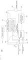
- FIG. 1 is a block diagram for describing a system according to an embodiment of the present disclosure.
- a system 100 may optimize the gas flow of ammonia in an industrial plant.
- the system 100 may include a physical plant 110, a data collection module 121, a simulation module 122, a feedback loop 123, a performance monitoring module 124, an update module 125, a feedback module 126, and a digital twin model 130.
- the physical plant 110 may include, for example, pipes 111, valves 112, pumps 113, and sensors 114.
- the data collection module 121 may acquire real-time data from the physical plant 110.
- the data collection module 121 may acquire real-time data about various environments from the sensors 114 included in the physical plant 110.
- the real-time data may include, for example, at least one of temperature, pressure, flow rate, pump speed, pipe characteristics, and valve position of the valves of the physical plant 110.
- the simulation module 122 may simulate at least one scenario using the digital twin model 130. Further, the simulation module 122 may identify optimal operating conditions for the gas flow of ammonia based on the simulation results.
- the simulation module 122 may minimize an energy consumption of the system 100 by adjusting operating conditions including at least one of the valve position, the pump speed, and the pipe characteristics. In addition, the simulation module 122 may maximize a throughput processed by the system 100.
- the simulation module 122 may collect an input indicating an energy amount required by the system 100 and an output of the physical plant 110 from the digital twin model 130.
- the simulation module 122 may collect the feed flow rate for a reforming reaction ("reforming reaction feed"), the flow rate of a feed for a combustion reaction (“combustion reaction feed”), and information on specific activity of catalysts in each reaction unit where the reforming reaction and combustion reaction occur from the digital twin model 130.
- the simulation module 122 may adjust, as an optimized scenario, an opening ratio of a flow rate control valve for each feed based on the collected information. For example, when an x data value is greater than a y data value, the opening rate may be adjusted by z.
- the feedback loop 123 may implement a feedback loop between the digital twin model 130 and the physical plant 110 to adjust the physical plant 110 based on the simulation results of the simulation module 122.
- the feedback loop 123 may adjust at least one of the pipe 111, the valve 112, the pump 113, and the sensor 114 included in the physical plant 110 in real time based on the simulation results of the simulation module 122.
- the performance monitoring module 124 may monitor the performance of the physical plant 110 to track the effectiveness of the optimization process.
- the performance monitoring module 124 may continuously monitor the performance of the physical plant 110 and the digital twin model 130 to determine whether the performances of the physical plant 110 and the digital twin model 130 satisfy preset targets.
- the update module 125 may continuously update parameter settings of the physical plant based on the real-time data of the physical plant 110 to ensure validity.
- the feedback module 126 may adjust the physical plant 110 in response to at least one optimized setting identified by the digital twin model 130.
- the digital twin model 130 is a digital model for the physical plant 110.
- the digital twin model 130 simulates the physical plant 110.
- the digital twin model 130 may include, for example, pipes, valves, pumps, and sensors which correspond to the pipes 131, valves 132, pumps 133, and sensors 134 of the physical plant.
- FIG. 2 is a relationship diagram between a plant and a digital twin model according to an embodiment of the present disclosure.
- a relationship diagram 200 may include a dynamic load input 210, a digital twin output amount control model 220, first and second blowers 231 and 232, a digital twin flow rate equal-distribution model 240, first information 250, first and second control valves 261 and 262, a reformer 270, a fuel cell 280, and second information 290.
- the dynamic load input 210, the first information 250, and the second information 290 may be inputs entered into the digital twin output amount control model 220.
- the first information 250 may include, for example, temperature, pressure, flow rate and the like.
- the second information 290 may include, for example, voltage, current and the like.
- the digital twin output amount control model 220 may transmit an output value to the first and second blowers 231 and 232.
- the reforming reaction feed may be fed into the first blower 231.
- Combustion reaction fuel and air may be fed into the second blower 232 as a feed.
- the second information 290 may be transmitted as input into the digital twin flow rate equal-distribution model 240.
- the digital twin flow rate equal-distribution model 240 may transmit an output value to the first and second control valves 261 and 262.
- the reforming reaction feed may be fed into the reformer 270 through the first control valve 261.
- the combustion reaction fuel and air may be fed into the reformer 270 through the second blower 232.
- a reaction may occur in the reformer 270.
- An electric power may be generated by the fuel cell 280.
- an input indicating the required energy amount may be collected in the digital twin output amount control model 220.
- the input indicating the required energy amount may include various parameters included, for example, in a graph indicating the energy amount required for decelerating or accelerating a vehicle, a graph indicating a change in the power consumption of a distributed power generation system by time and the like.
- the electric power output of fuel cells sensed from the physical plant may be collected in the digital twin output amount control model 220.
- the flow rate of the feed for a reforming reaction occurring in the reformer 270 for example, the reforming reaction feed, may be collected in the digital twin flow rate equal-distribution model 240.
- the flow rate of feed for a combustion reaction may be collected in the digital twin flow rate equal-distribution model 240.
- the information on the specific activity of the catalysts in each reaction unit where the reforming reaction and combustion reaction occur may be collected in the digital twin flow rate equal-distribution model 240.
- the specific activity of the catalyst may be obtained by measuring the temperature, composition, and flow rate of a reforming reaction product and the combustion flue gas, and calculating a conversion rate and selectivity.
- the opening rate of the flow rate control valve for each feed may be adjusted based on the collected information. In this case, the higher the specific activity of the catalyst, the less feed may be injected.
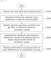
- FIG. 3 is a flow chart illustrating procedures of a method according to an embodiment of the present disclosure.
- the method according to an embodiment of the present disclosure may optimize the gas flow of ammonia in an industrial plant.
- a step of acquiring real-time data from the physical plant is performed (S100).
- the simulation module 122 may simulate at least one scenario using the digital twin model 130 and identify optimal operating conditions for the gas flow of ammonia based on the simulation results.
- the operating conditions may include, for example, the valve position, pump speed, and pipe characteristics.
- the simulation module 122 may collect an input indicating the energy amount required by the system 100, an output of the physical plant 110, a flow rate of the feed for a reforming reaction, a flow rate of the feed for a combustion reaction, and information on the specific activity of the catalysts in each reaction unit where the reforming reaction and combustion reaction occur in the digital twin model 130.
- the simulation module 122 may adjust an opening rate of the flow rate control valve for the feed based on the collected information.
- the feedback loop 123 may implement a feedback loop between the digital twin model 130 and the physical plant 110 to adjust the physical plant 110 based on the simulation results of the simulation module 122, and regulate at least one of the pipe 111, the valve 112, the pump 113, and the sensor 114 included in the physical plant 110 in real time.
- the performance monitoring module 124 may continuously monitor the performance of the physical plant 110 and the digital twin model 130 to track the effectiveness of the optimization process, such that it can be confirmed whether the performances of the physical plant 110 and the digital twin model 130 satisfy the preset targets.
- the disclosed embodiments may be implemented in the form of a recording medium which stores instructions executable by a computer.
- the instructions may be stored in the form of program code, and when executed by the processor, may generate a program module to perform operations of the disclosed embodiments.
- the recording medium may be implemented as a computer-readable recording medium.
- the computer-readable recording medium may include all types of recording media in which instructions that can be decoded by the computer are stored. For example, there may be a read only memory (ROM), random access memory (RAM), magnetic tape, magnetic disk, flash memory, optical data storage device and the like.
- ROM read only memory
- RAM random access memory
- magnetic tape magnetic tape
- magnetic disk magnetic disk
- flash memory optical data storage device and the like.
Landscapes
- Engineering & Computer Science (AREA)
- Physics & Mathematics (AREA)
- General Physics & Mathematics (AREA)
- Automation & Control Theory (AREA)
- Manufacturing & Machinery (AREA)
- Quality & Reliability (AREA)
- General Engineering & Computer Science (AREA)
- Evolutionary Computation (AREA)
- Theoretical Computer Science (AREA)
- Computer Vision & Pattern Recognition (AREA)
- Medical Informatics (AREA)
- Artificial Intelligence (AREA)
- Health & Medical Sciences (AREA)
- Software Systems (AREA)
- Mathematical Analysis (AREA)
- Geometry (AREA)
- Computer Hardware Design (AREA)
- Pure & Applied Mathematics (AREA)
- Mathematical Physics (AREA)
- Mathematical Optimization (AREA)
- Fluid Mechanics (AREA)
- Computing Systems (AREA)
- Algebra (AREA)
- Feedback Control In General (AREA)
- Fuel Cell (AREA)
- Testing And Monitoring For Control Systems (AREA)
Abstract
Disclosed are a system and a method for optimizing a gas flow of ammonia in an industrial plant. The system according to the present disclosure may include: a physical plant; a digital twin model for the physical plant; a data collection module configured to acquire real-time data from the physical plant; a simulation module configured to simulate at least one scenario using the digital twin model and identify optimal operating conditions for the gas flow of ammonia based on simulation results; a feedback loop between the digital twin model and the physical plant to adjust the physical plant based on the simulation results; and a performance monitoring module configured to monitor performance of the physical plant to track effectiveness of the optimization process.
Description
- The present disclosure relates to a system and a method for optimizing a flow of ammonia. It further relates to a computer-readable medium.
- Recently, as various environmental problems are becoming a major issue throughout the world, demand for the introduction of eco-friendly alternative energy instead of existing internal combustion engines not only for general vehicles but also for heavy equipment such as an excavator is increasing. Thereby, a fuel cell system which uses fuel cells (FCs) as a power source has been in the spotlight.
- In order to ensure smooth operation and high performance of the fuel cell system, the role of an Energy Management System (EMS) is important to appropriately determine how to distribute power demands between the power sources. To this end, stable and reliable operation of the EMS is required.
- In a situation where a plurality of pipes exist, when the flow rate is concentrated in a specific pipe, it is necessary to equalize the flow rate by automatically reducing the flow rate of the corresponding pipe. It is difficult to describe the complex interaction between different components of the system by conventional methods. To solve this problem, digital twins (DTs) are being developed for providing accurate a real-time simulation of entire physical system.
- According to one aspect of the present disclosure, it is an object to provide a system and a method for controlling a flow rate of a gas such as ammonia flowing in a specific pipe in an industrial plant, in which the flow rate is concentrated, among a plurality of pipes.
- In addition, according to one aspect of the present disclosure, it is another object to provide a system and a method for optimizing a flow of ammonia using digital twin technologies.
- To achieve the above objects, according to an aspect of the present invention, there is provided a system for optimizing a gas flow of ammonia in an industrial plant, the system including: a physical plant; a digital twin model for the physical plant; a data collection module configured to acquire real-time data from the physical plant; a simulation module configured to simulate at least one scenario using the digital twin model and identify optimal operating conditions for the gas flow of ammonia based on simulation results; a feedback loop between the digital twin model and the physical plant to adjust the physical plant based on the simulation results; and a performance monitoring module configured to monitor performance of the physical plant to track effectiveness of the optimization process.
- According to an embodiment, the physical plant may include pipes, valves, pumps, and sensors.
- According to an embodiment, the data collection module is configured to collect the real-time data including at least one of temperature, pressure, flow rate, pump speed, pipe characteristics, and valve position from the sensors.
- According to an embodiment, the simulation module is configured to minimize an energy consumption of the system by adjusting operating conditions including at least one of the valve position, the pump speed, and the pipe characteristics, and maximize a throughput processed in the system.
- According to an embodiment, the feedback loop is configured to adjust at least one of pipes, valves, pumps, and sensors included in the physical plant in real time based on the simulation results.
- According to an embodiment, the performance monitoring module is configured to continuously monitor the performance of the physical plant and the digital twin model to determine whether the performances of the physical plant and the digital twin model satisfy preset targets.
- According to an embodiment, the system may further include an update module configured to continuously update parameter settings of the physical plant based on the real-time data of the physical plant.
- According to an embodiment, the system may further include a feedback module configured to adjust the physical plant in response to optimized settings identified by the digital twin model.
- According to an embodiment, the simulation module may be configured to: collect an input indicating an energy amount required by the system and an output of the physical plant from the digital twin model; collect a flow rate of the feed for a reforming reaction, a flow rate of the feed for a combustion reaction, and information on specific activity of catalysts in each reaction unit where the reforming reaction and combustion reaction occur from the digital twin model; and adjust, as an optimized scenario, an opening ratio of a flow rate control valve for each feed based on the collected information.
- According to another aspect of the present invention, there is provided a method for optimizing a gas flow of ammonia in an industrial plant, the method including: obtaining real-time data from a physical plant; simulating at least one scenario using a digital twin model for the physical plant; identifying optimal operating conditions for the gas flow of ammonia based on simulation results; implementing a feedback loop between the digital twin model and the physical plant to adjust the physical plant based on the simulation results; and monitoring performance of the physical plant to track the effectiveness of the optimization process.
- According to another aspect of the present invention, the following data are collected: an input indicating the energy amount required by the system, an output of the physical plant, a flow rate of the feed for a reforming reaction, a flow rate of the feed for a combustion reaction, and information on the specific activity of the catalysts in each reaction unit where the reforming reaction and combustion reaction occur.
- According to another aspect of the present invention, operating conditions include a valve position, a pump speed, and pipe characteristics, wherein the valve, the pump and the pipe are included in an industrial plant.
- According to another aspect of the present invention, the feedback loop further regulates at least one of a pipe, a valve, a pump, and a sensor included in the
physical plant 110 in real time. - According to another aspect of the present invention, the performance of the physical plant) and the digital twin model are continuously monitored to track the effectiveness of the optimization process in order to confirm whether the performances of the physical plant and the digital twin model satisfy the targets.
- According to another aspect of the present invention, a computer-readable medium, is provided, which stores instructions in the form of program code, which, when executed by a processor, is configured to generate a program module to perform operations for controlling a flow rate of ammonia flowing in a specific pipe of an industrial plant, in which the flow rate is concentrated, among a plurality of pipes.
- According to an embodiment of the present disclosure, by optimizing the flow of gas such as ammonia, there are effects of improving effectiveness of the entire process, such as maximizing the throughput of ammonia, minimizing energy consumption, and identifying optimal operating conditions.
- In addition, according to an embodiment of the present disclosure, by optimizing the flow of gas, there are effects of improving the environmental impact, such as preventing the emission of harmful emissions.
- In addition, according to an embodiment of the present disclosure, by preventing potential system errors or malfunctions in the physical plant, reliability of the system may be improved.
- Further, according to an embodiment of the present disclosure, by providing real-time responses to changing conditions through the feedback loop between the digital twin model and the physical plant, there are effects of quickly performing the control operation, adjustment operation, regulation operation and the like.
- The above and other objects, features and other advantages of the present invention will be more clearly understood from the following detailed description taken in conjunction with the accompanying drawings, in which:
-
FIG. 1 is a block diagram for describing a system according to an embodiment of the present disclosure; -
FIG. 2 is a relationship diagram between a plant and a digital twin model according to an embodiment of the present disclosure; and -
FIG. 3 is a flow chart illustrating procedures of a method according to an embodiment of the present disclosure. - Hereinafter, the present disclosure will be described in detail through embodiments with reference to the accompanying drawings. However, the embodiments are merely illustrative and the present disclosure is not limited to the specific embodiments described by way of example.
- The same reference numerals are denoted to the same components throughout the present disclosure. The present disclosure does not describe all elements of the embodiments, and general contents in the technical field to which the present disclosure pertains or overlapping contents between the embodiments will not be described. The terms `unit, module, member and block' used herein may be implemented as software or hardware, and depending on the embodiments, a plurality of `units, modules, members and blocks' may be implemented as one component, or one 'part, module, member, or block' may include a plurality of components.
- Throughout the specification, when the explanatory phrase a part is "connected" to another part is used, this includes not only the case where the part is "directly connected" to the other part, but also the case where the part is "indirectly connected" to the other part, and the indirect connection includes connection through a wireless communication network.
- In addition, when the explanatory phrase a part "comprises or includes" a component is used, this means that the part may further include the component without excluding other components, unless there is a description opposite thereto.
- Throughout the specification, when the explanatory phrase a member is located "on" another member is used, this includes not only the case where the member is in contact with the other member, but also the case where another member exists between the two members.
- Terms such as first and second, etc. are used to distinguish one component from another component, and the components are not limited by the above-described terms.
- The singular forms "a," "an" and "the" are intended to include the plural forms as well, unless the context clearly indicates otherwise.
- The identification numerals for each step is used for the convenience of description. The identification numerals do not describe the order of each step, and each step may be performed differently from the specified order unless a specific order is clearly described in the context.
- In this specification, the 'device according to the present disclosure' includes all various devices that may perform computational processing and provide results thereof to a user. For example, the device according to the present disclosure may include all of a computer, a server device and a portable terminal, or may be any form thereof.
- Here, the computer may include, for example, a laptop or desktop computer, laptop PC, tablet PC, slate PC, and the like equipped with a web browser.
- The server device is a server that processes information by performing communication with an external device, and may include an application server, computing server, database server, file server, game server, mail server, proxy server and web server.
- The portable terminal is, for example, a wireless communication device with which portability and mobility are assured, and may include: all types of handheld wireless communication devices such as a personal communication system (PCS), global system for mobile communications (GSM), personal digital cellular (PDC), personal handy phone system (PHS), personal digital assistant (PDA), international mobile telecommunication (IMT)-2000, code division multiple access (CDMA)-2000, wideband code division multiple access (W-CDMA), wireless broadband internet (WiBro) terminal, and smart phone, etc.; and wearable devices such as a watch, ring, bracelet, anklet, necklace, glasses, contact lenses, and head-mounted-device (HMD), etc.
-
FIG. 1 is a block diagram for describing a system according to an embodiment of the present disclosure. - Referring to
FIG. 1 , asystem 100 may optimize the gas flow of ammonia in an industrial plant. Thesystem 100 may include aphysical plant 110, adata collection module 121, asimulation module 122, afeedback loop 123, aperformance monitoring module 124, anupdate module 125, afeedback module 126, and adigital twin model 130. - The
physical plant 110 may include, for example,pipes 111,valves 112,pumps 113, andsensors 114. - The
data collection module 121 may acquire real-time data from thephysical plant 110. Thedata collection module 121 may acquire real-time data about various environments from thesensors 114 included in thephysical plant 110. The real-time data may include, for example, at least one of temperature, pressure, flow rate, pump speed, pipe characteristics, and valve position of the valves of thephysical plant 110. - The
simulation module 122 may simulate at least one scenario using the digitaltwin model 130. Further, thesimulation module 122 may identify optimal operating conditions for the gas flow of ammonia based on the simulation results. - The
simulation module 122 may minimize an energy consumption of thesystem 100 by adjusting operating conditions including at least one of the valve position, the pump speed, and the pipe characteristics. In addition, thesimulation module 122 may maximize a throughput processed by thesystem 100. - The
simulation module 122 may collect an input indicating an energy amount required by thesystem 100 and an output of thephysical plant 110 from the digitaltwin model 130. In addition, thesimulation module 122 may collect the feed flow rate for a reforming reaction ("reforming reaction feed"), the flow rate of a feed for a combustion reaction ("combustion reaction feed"), and information on specific activity of catalysts in each reaction unit where the reforming reaction and combustion reaction occur from the digitaltwin model 130. Further, thesimulation module 122 may adjust, as an optimized scenario, an opening ratio of a flow rate control valve for each feed based on the collected information. For example, when an x data value is greater than a y data value, the opening rate may be adjusted by z. - The
feedback loop 123 may implement a feedback loop between the digitaltwin model 130 and thephysical plant 110 to adjust thephysical plant 110 based on the simulation results of thesimulation module 122. - The
feedback loop 123 may adjust at least one of thepipe 111, thevalve 112, thepump 113, and thesensor 114 included in thephysical plant 110 in real time based on the simulation results of thesimulation module 122. - The
performance monitoring module 124 may monitor the performance of thephysical plant 110 to track the effectiveness of the optimization process. - The
performance monitoring module 124 may continuously monitor the performance of thephysical plant 110 and the digitaltwin model 130 to determine whether the performances of thephysical plant 110 and the digitaltwin model 130 satisfy preset targets. - The
update module 125 may continuously update parameter settings of the physical plant based on the real-time data of thephysical plant 110 to ensure validity. - The
feedback module 126 may adjust thephysical plant 110 in response to at least one optimized setting identified by the digitaltwin model 130. - The digital
twin model 130 is a digital model for thephysical plant 110. In other words, the digitaltwin model 130 simulates thephysical plant 110. The digitaltwin model 130 may include, for example, pipes, valves, pumps, and sensors which correspond to thepipes 131,valves 132, pumps 133, andsensors 134 of the physical plant. - According to the above description, by optimizing the flow of gas such as ammonia, there are effects of improving effectiveness of the entire process, such as maximizing the throughput of ammonia, minimizing energy consumption, and identifying optimal operating conditions.
- In addition, according to the above description, by optimizing the flow of gas, there are effects of improving the environmental impact, such as preventing the emission of harmful emissions.
- In addition, according to the above description, by preventing potential system errors or malfunctions in the physical plant, reliability of the system may be improved.
- In addition, according to the above description, by providing real-time responses to changing conditions through the feedback loop between the digital twin model and the physical plant, there are effects of quickly perform the control operation, adjustment operation, regulation operation and the like.
-
FIG. 2 is a relationship diagram between a plant and a digital twin model according to an embodiment of the present disclosure. - Referring to
FIG. 2 , a relationship diagram 200 may include adynamic load input 210, a digital twin outputamount control model 220, first andsecond blowers distribution model 240,first information 250, first andsecond control valves reformer 270, afuel cell 280, andsecond information 290. - The
dynamic load input 210, thefirst information 250, and thesecond information 290 may be inputs entered into the digital twin outputamount control model 220. Thefirst information 250 may include, for example, temperature, pressure, flow rate and the like. Thesecond information 290 may include, for example, voltage, current and the like. - The digital twin output
amount control model 220 may transmit an output value to the first andsecond blowers - The reforming reaction feed may be fed into the
first blower 231. Combustion reaction fuel and air may be fed into thesecond blower 232 as a feed. - The
second information 290 may be transmitted as input into the digital twin flow rate equal-distribution model 240. The digital twin flow rate equal-distribution model 240 may transmit an output value to the first andsecond control valves reformer 270 through thefirst control valve 261. The combustion reaction fuel and air may be fed into thereformer 270 through thesecond blower 232. - A reaction may occur in the
reformer 270. An electric power may be generated by thefuel cell 280. - For the optimized scenario described above with reference to
FIG. 1 , an input indicating the required energy amount, for example, thedynamic load input 210, may be collected in the digital twin outputamount control model 220. The input indicating the required energy amount may include various parameters included, for example, in a graph indicating the energy amount required for decelerating or accelerating a vehicle, a graph indicating a change in the power consumption of a distributed power generation system by time and the like. In addition, the electric power output of fuel cells sensed from the physical plant may be collected in the digital twin outputamount control model 220. The flow rate of the feed for a reforming reaction occurring in thereformer 270, for example, the reforming reaction feed, may be collected in the digital twin flow rate equal-distribution model 240. The flow rate of feed for a combustion reaction, for example, the combustion reaction fuel and air, may be collected in the digital twin flow rate equal-distribution model 240. The information on the specific activity of the catalysts in each reaction unit where the reforming reaction and combustion reaction occur may be collected in the digital twin flow rate equal-distribution model 240. The specific activity of the catalyst may be obtained by measuring the temperature, composition, and flow rate of a reforming reaction product and the combustion flue gas, and calculating a conversion rate and selectivity. The opening rate of the flow rate control valve for each feed may be adjusted based on the collected information. In this case, the higher the specific activity of the catalyst, the less feed may be injected. -
FIG. 3 is a flow chart illustrating procedures of a method according to an embodiment of the present disclosure. - Referring to
FIG. 3 , the method according to an embodiment of the present disclosure may optimize the gas flow of ammonia in an industrial plant. - First, a step of acquiring real-time data from the physical plant is performed (S100).
- Then, a step of simulating at least one scenario using a digital twin model for the physical plant is performed (S200).
- Next, a step of identifying optimal operating conditions for the gas flow of ammonia is performed based on the simulation results (S300).
- When exemplifying in relation to the step S200 and step S300 with reference to
FIG. 1 , thesimulation module 122 may simulate at least one scenario using the digitaltwin model 130 and identify optimal operating conditions for the gas flow of ammonia based on the simulation results. Here, the operating conditions may include, for example, the valve position, pump speed, and pipe characteristics. Thesimulation module 122 may collect an input indicating the energy amount required by thesystem 100, an output of thephysical plant 110, a flow rate of the feed for a reforming reaction, a flow rate of the feed for a combustion reaction, and information on the specific activity of the catalysts in each reaction unit where the reforming reaction and combustion reaction occur in the digitaltwin model 130. In addition, thesimulation module 122 may adjust an opening rate of the flow rate control valve for the feed based on the collected information. - Then, a step of implementing a feedback loop between the digital twin model and the physical plant to adjust the physical plant is performed based on the simulation results (S400).
- When exemplifying in relation to the step S400 with reference to
FIG. 1 , thefeedback loop 123 may implement a feedback loop between the digitaltwin model 130 and thephysical plant 110 to adjust thephysical plant 110 based on the simulation results of thesimulation module 122, and regulate at least one of thepipe 111, thevalve 112, thepump 113, and thesensor 114 included in thephysical plant 110 in real time. - Finally, a step of monitoring the performance of the physical plant to track the effectiveness of the optimization process is performed (S500).
- When exemplifying in relation to the step S500 with reference to
FIG. 1 , theperformance monitoring module 124 may continuously monitor the performance of thephysical plant 110 and the digitaltwin model 130 to track the effectiveness of the optimization process, such that it can be confirmed whether the performances of thephysical plant 110 and the digitaltwin model 130 satisfy the preset targets. - Meanwhile, the disclosed embodiments may be implemented in the form of a recording medium which stores instructions executable by a computer. The instructions may be stored in the form of program code, and when executed by the processor, may generate a program module to perform operations of the disclosed embodiments. The recording medium may be implemented as a computer-readable recording medium.
- The computer-readable recording medium may include all types of recording media in which instructions that can be decoded by the computer are stored. For example, there may be a read only memory (ROM), random access memory (RAM), magnetic tape, magnetic disk, flash memory, optical data storage device and the like.
- As above, the disclosed embodiments have been described with reference to the accompanying drawings. It will be understood by persons skilled in the art to which the present disclosure pertains that the present disclosure may be embodied in forms different from the disclosed embodiments without changing the technical idea or essential features of the present disclosure. The disclosed embodiments are illustrative, and should not be interpreted as limiting.
Claims (15)
- A system (100) for optimizing a gas flow of ammonia in an industrial plant, the system (100) comprising:a physical plant (110);a digital twin model (130) for the physical plant (110);a data collection module (121) configured to acquire real-time data from the physical plant (110);a simulation module (122) configured to simulate at least one scenario using the digital twin model (130) and to identify optimal operating conditions for the gas flow of ammonia based on simulation results;a feedback loop (123) between the digital twin model (130) and the physical plant (110) to adjust the physical plant (110) based on the simulation results; anda performance monitoring module (124) configured to monitor performance of the physical plant (110) to track the effectiveness of the optimization process.
- The system according to claim 1, wherein the physical plant (110) comprises pipes, valves, pumps, and sensors (114, 134) .
- The system according to claim 1 or 2, wherein the data collection module (121) is configured to collect the real-time data including at least one of temperature, pressure, flow rate, pump speed, pipe characteristics, and valve position from the sensors (114, 134).
- The system according to any one of claims 1 to 3, wherein the simulation module (122) is configured to minimize an energy consumption of the system (100) by adjusting operating conditions including at least one of the valve position, the pump speed, and the pipe characteristics, and to maximize a throughput processed in the system (100).
- The system according to any one of claims 1 to 4, wherein the feedback loop is configured to adjust at least one of pipes, valves, pumps, and sensors (114, 134) included in the physical plant (110) in real time based on the simulation results.
- The system according to any one of claims 1 to 5, wherein the performance monitoring module (124) is configured to continuously monitor the performance of the physical plant (110) and the digital twin model (130) to determine whether the performances of the physical plant (110) and the digital twin model (130) satisfy preset targets.
- The system according to any one of claims 1 to 6, further comprising an update module (125) configured to continuously update parameter settings of the physical plant (110) based on the real-time data of the physical plant (110).
- The system according to any one of claims 1 to 7, further comprising a feedback module (126) configured to adjust the physical plant (110) in response to at least one optimized setting identified by the digital twin model (130).
- The system according to any one of claims 1 to 8, wherein the simulation module (122) is configured to:collect an input (210) indicating an energy amount required by the system (100) and an output of the physical plant (110) from the digital twin model (130);collect a feed flow rate for a reforming reaction, a feed flow rate for a combustion reaction, and information on specific activity of catalysts in each reaction unit where the reforming reaction and combustion reaction occur from the digital twin model (130); andadjust, as an optimized scenario, an opening ratio of a flow rate control valve for each feed based on the collected information.
- A method for optimizing a gas flow of ammonia in an industrial plant, the method comprising:obtaining real-time data from a physical plant (110);simulating at least one scenario using a digital twin model (130) for the physical plant (110);identifying optimal operating conditions for the gas flow of ammonia based on simulation results;implementing a feedback loop (123) between the digital twin model (130) and the physical plant (110) to adjust the physical plant (110) based on the simulation results; andmonitoring performance of the physical plant (110) to track the effectiveness of the optimization process.
- The method according to claim 10, wherein one or more of or all of the following data are collected: an input indicating the energy amount required by the system (100), an output of the physical plant (110), a flow rate of the feed for a reforming reaction, a flow rate of the feed for a combustion reaction, and information on the specific activity of the catalysts in each reaction unit where the reforming reaction and combustion reaction occur.
- The method according to claim 10 or 11, wherein operating conditions include a valve position, a pump speed, and pipe characteristics.
- The method according to one of claims 10 to 12, wherein the feedback loop further regulates at least one of a pipe (111), a valve (112), a pump (113), and a sensor (114) included in the physical plant (110) in real time.
- The method according to one of claims 10 to 13, wherein the performance of the physical plant (110) and the digital twin model (130) are continuously monitored to track the effectiveness of the optimization process in order to confirm whether the performances of the physical plant (110) and the digital twin model (130) satisfy the targets.
- Computer-readable medium, which stores instructions in the form of program code, which, when executed by a processor, is configured to generate a program module to perform operations for controlling a flow rate of ammonia flowing in a specific pipe of an industrial plant, in which the flow rate is concentrated, among a plurality of pipes; optionally wherein the computer-readable medium stores instructions in the form of a program code which, when executed by a processor, is configured to generate the program module to perform operations of the method of any one of claims 10 to 14.
Applications Claiming Priority (1)
| Application Number | Priority Date | Filing Date | Title |
|---|---|---|---|
| KR1020230095393A KR102732049B1 (en) | 2023-07-21 | 2023-07-21 | System and mehtod for optimizing flow of ammonia utilizing digital twin technology |
Publications (1)
| Publication Number | Publication Date |
|---|---|
| EP4495714A1 true EP4495714A1 (en) | 2025-01-22 |
Family
ID=91737708
Family Applications (1)
| Application Number | Title | Priority Date | Filing Date |
|---|---|---|---|
| EP24185335.7A Pending EP4495714A1 (en) | 2023-07-21 | 2024-06-28 | System and method for optimizing flow of ammonia, and computer-readable medium |
Country Status (6)
| Country | Link |
|---|---|
| US (1) | US20250028308A1 (en) |
| EP (1) | EP4495714A1 (en) |
| JP (1) | JP7755680B2 (en) |
| KR (1) | KR102732049B1 (en) |
| CN (1) | CN119337756A (en) |
| AU (1) | AU2024204807B2 (en) |
Families Citing this family (1)
| Publication number | Priority date | Publication date | Assignee | Title |
|---|---|---|---|---|
| CN120161177B (en) * | 2025-05-19 | 2025-08-29 | 成都职业技术学院 | A material pollutant release detection system |
Citations (3)
| Publication number | Priority date | Publication date | Assignee | Title |
|---|---|---|---|---|
| WO1995028666A1 (en) * | 1994-04-13 | 1995-10-26 | The M.W. Kellogg Company | Maximizing process production rates using permanent constraints |
| EP3825949A1 (en) * | 2019-11-19 | 2021-05-26 | Linde GmbH | Online plant optimizer for operating, performance rating, energy nd cost optimization and design of a process plant and integration with a smart plant three-dimensional piping model |
| US20220403775A1 (en) * | 2021-05-14 | 2022-12-22 | Amogy Inc. | Systems and methods for processing ammonia |
Family Cites Families (13)
| Publication number | Priority date | Publication date | Assignee | Title |
|---|---|---|---|---|
| JP2005093120A (en) * | 2003-09-12 | 2005-04-07 | Toyota Motor Corp | Fuel cell control device and control method |
| US9650269B2 (en) * | 2014-11-25 | 2017-05-16 | General Electric Technology Gmbh | System and method for reducing gas emissions from wet flue gas desulfurization waste water |
| JP6582011B2 (en) | 2017-03-17 | 2019-09-25 | 澤藤電機株式会社 | Transportation equipment with fuel cell system |
| JP7285098B2 (en) * | 2019-03-15 | 2023-06-01 | 三菱重工業株式会社 | Ammonia decomposition equipment, gas turbine plant equipped with same, ammonia decomposition method |
| EP3974640A4 (en) | 2019-05-22 | 2023-09-06 | National Institute of Maritime, Port and Aviation Technology | METHOD FOR MONITORING THE MAIN ENGINE OF A SHIP, SYSTEM FOR MONITORING THE MAIN ENGINE, SYSTEM FOR PREDICTING THE MAIN ENGINE CONDITION AND SYSTEM FOR PREDICTING THE OPERATING CONDITION |
| KR102344852B1 (en) * | 2019-11-20 | 2021-12-28 | 한국수력원자력 주식회사 | Digital Twin-based Prediction and Diagnostic Device for Pump Bearing Systems |
| KR102212390B1 (en) * | 2020-04-01 | 2021-02-04 | (주)포미트 | Apparatus and method for deriving optimum operating rule of real plant using digital twin simulator and machine learning |
| JP7539498B2 (en) | 2021-01-29 | 2024-08-23 | Agc株式会社 | Information processing system and automated driving assistance method |
| KR102632527B1 (en) | 2021-09-08 | 2024-02-02 | 울산대학교 산학협력단 | System and method for fault diagnosis of fuel cell energy management system based on digital twin |
| JP7643272B2 (en) * | 2021-09-17 | 2025-03-11 | トヨタ自動車株式会社 | Driving Skills Evaluation System |
| EP4406040A4 (en) | 2021-09-20 | 2025-08-20 | Univ Hong Kong Polytechnic | ENERGY STORAGE SYSTEMS AND AMMONIA-POWERED ELECTRIC VEHICLES |
| JP7633920B2 (en) * | 2021-11-05 | 2025-02-20 | 株式会社日立製作所 | Simulator system and simulator method |
| KR102511020B1 (en) * | 2022-08-17 | 2023-03-16 | 주식회사 플로워크연구소 | Method for monitoring pipe system and server using the same |
-
2023
- 2023-07-21 KR KR1020230095393A patent/KR102732049B1/en active Active
-
2024
- 2024-03-12 CN CN202410280068.3A patent/CN119337756A/en active Pending
- 2024-03-22 JP JP2024047211A patent/JP7755680B2/en active Active
- 2024-06-28 EP EP24185335.7A patent/EP4495714A1/en active Pending
- 2024-07-02 US US18/761,329 patent/US20250028308A1/en active Pending
- 2024-07-12 AU AU2024204807A patent/AU2024204807B2/en active Active
Patent Citations (3)
| Publication number | Priority date | Publication date | Assignee | Title |
|---|---|---|---|---|
| WO1995028666A1 (en) * | 1994-04-13 | 1995-10-26 | The M.W. Kellogg Company | Maximizing process production rates using permanent constraints |
| EP3825949A1 (en) * | 2019-11-19 | 2021-05-26 | Linde GmbH | Online plant optimizer for operating, performance rating, energy nd cost optimization and design of a process plant and integration with a smart plant three-dimensional piping model |
| US20220403775A1 (en) * | 2021-05-14 | 2022-12-22 | Amogy Inc. | Systems and methods for processing ammonia |
Also Published As
| Publication number | Publication date |
|---|---|
| CN119337756A (en) | 2025-01-21 |
| JP7755680B2 (en) | 2025-10-16 |
| US20250028308A1 (en) | 2025-01-23 |
| AU2024204807B2 (en) | 2026-01-15 |
| KR102732049B1 (en) | 2024-11-18 |
| JP2025016333A (en) | 2025-01-31 |
| AU2024204807A1 (en) | 2025-02-06 |
Similar Documents
| Publication | Publication Date | Title |
|---|---|---|
| EP3987363B1 (en) | Method and system for optimization of combined cycle gas turbine operation | |
| CN111765445A (en) | A kind of boiler online combustion optimization control method, system and computer equipment | |
| US20250028308A1 (en) | System and method for optimizing flow of ammonia | |
| Li et al. | Innovative distribution network design using GAN‐based distributionally robust optimization for DG planning | |
| CN119721556A (en) | A method and system for optimizing risk dispatch of power system | |
| EP4530778A1 (en) | System and method for managing ammonia cracking plant, and computer-readable medium | |
| WO2022067676A1 (en) | Load moving method and apparatus, and computer-readable storage medium | |
| CN112149901B (en) | A method and device for predicting the pressure field of the low-pressure final stage of a steam turbine | |
| CN118534857B (en) | Industrial waste gas treatment control method and system | |
| CN112560325B (en) | Prediction method, system, equipment and storage medium for electricity conversion service | |
| KR102735999B1 (en) | Electronic apparatus and method for generating path information of mobile device | |
| CN118915840A (en) | Denitration ammonia injection amount control method and device | |
| Sun et al. | Networked control of distributed energy resources: Application to solid oxide fuel cells | |
| CN116488149A (en) | Microgrid power generation strategy determination method, device and microgrid | |
| Wang et al. | Optimization technology of combustion engine control based on swarm intelligent optimization algorithm and improved clustering algorithm | |
| Li et al. | Empowering telecommunication towers employing improved war strategy optimization method | |
| EP4495056A2 (en) | Hydrogen cracking apparatus, hydrogen cracking method using the same and energy generation system | |
| KR20240088097A (en) | Factory monitoring device for monitoring process efficiency and process improving method | |
| Ayvaz | An enhanced sparrow search algorithm for model order reduction of proton exchange membrane fuel cell system | |
| CN118586794B (en) | Data analysis and processing method for energy storage energy-saving system | |
| US12422798B1 (en) | Process adjustment control method and syetem based on production line co-production | |
| CN119414788B (en) | Methods, devices, electronic equipment, and media for controlling the consistency of anti-poisoning performance in the batch preparation of solid hydrogen storage alloys. | |
| CN110087194B (en) | Game-based position data poisoning attack prototype system in Internet of vehicles | |
| CN119521613A (en) | An airflow organization energy-saving optimization system and method for a data center computer room | |
| CN121618464A (en) | Frequency modulation power distribution coefficient optimization sending and receiving end multi-resource power distribution method |
Legal Events
| Date | Code | Title | Description |
|---|---|---|---|
| PUAI | Public reference made under article 153(3) epc to a published international application that has entered the european phase |
Free format text: ORIGINAL CODE: 0009012 |
|
| STAA | Information on the status of an ep patent application or granted ep patent |
Free format text: STATUS: REQUEST FOR EXAMINATION WAS MADE |
|
| 17P | Request for examination filed |
Effective date: 20240628 |
|
| AK | Designated contracting states |
Kind code of ref document: A1 Designated state(s): AL AT BE BG CH CY CZ DE DK EE ES FI FR GB GR HR HU IE IS IT LI LT LU LV MC ME MK MT NL NO PL PT RO RS SE SI SK SM TR |