EP4495613A1 - Battery capacity calculation device and battery capacity calculation method - Google Patents
Battery capacity calculation device and battery capacity calculation method Download PDFInfo
- Publication number
- EP4495613A1 EP4495613A1 EP24182047.1A EP24182047A EP4495613A1 EP 4495613 A1 EP4495613 A1 EP 4495613A1 EP 24182047 A EP24182047 A EP 24182047A EP 4495613 A1 EP4495613 A1 EP 4495613A1
- Authority
- EP
- European Patent Office
- Prior art keywords
- battery
- capacity
- full charge
- impedance
- value
- Prior art date
- Legal status (The legal status is an assumption and is not a legal conclusion. Google has not performed a legal analysis and makes no representation as to the accuracy of the status listed.)
- Pending
Links
Images




Classifications
-
- G—PHYSICS
- G01—MEASURING; TESTING
- G01R—MEASURING ELECTRIC VARIABLES; MEASURING MAGNETIC VARIABLES
- G01R31/00—Arrangements for testing electric properties; Arrangements for locating electric faults; Arrangements for electrical testing characterised by what is being tested not provided for elsewhere
- G01R31/36—Arrangements for testing, measuring or monitoring the electrical condition of accumulators or electric batteries, e.g. capacity or state of charge [SoC]
- G01R31/385—Arrangements for measuring battery or accumulator variables
- G01R31/387—Determining ampere-hour charge capacity or SoC
- G01R31/388—Determining ampere-hour charge capacity or SoC involving voltage measurements
-
- B—PERFORMING OPERATIONS; TRANSPORTING
- B60—VEHICLES IN GENERAL
- B60L—PROPULSION OF ELECTRICALLY-PROPELLED VEHICLES; SUPPLYING ELECTRIC POWER FOR AUXILIARY EQUIPMENT OF ELECTRICALLY-PROPELLED VEHICLES; ELECTRODYNAMIC BRAKE SYSTEMS FOR VEHICLES IN GENERAL; MAGNETIC SUSPENSION OR LEVITATION FOR VEHICLES; MONITORING OPERATING VARIABLES OF ELECTRICALLY-PROPELLED VEHICLES; ELECTRIC SAFETY DEVICES FOR ELECTRICALLY-PROPELLED VEHICLES
- B60L58/00—Methods or circuit arrangements for monitoring or controlling batteries or fuel cells, specially adapted for electric vehicles
- B60L58/10—Methods or circuit arrangements for monitoring or controlling batteries or fuel cells, specially adapted for electric vehicles for monitoring or controlling batteries
- B60L58/16—Methods or circuit arrangements for monitoring or controlling batteries or fuel cells, specially adapted for electric vehicles for monitoring or controlling batteries responding to battery ageing, e.g. to the number of charging cycles or the state of health [SoH]
-
- G—PHYSICS
- G01—MEASURING; TESTING
- G01R—MEASURING ELECTRIC VARIABLES; MEASURING MAGNETIC VARIABLES
- G01R31/00—Arrangements for testing electric properties; Arrangements for locating electric faults; Arrangements for electrical testing characterised by what is being tested not provided for elsewhere
- G01R31/36—Arrangements for testing, measuring or monitoring the electrical condition of accumulators or electric batteries, e.g. capacity or state of charge [SoC]
- G01R31/3644—Constructional arrangements
- G01R31/3648—Constructional arrangements comprising digital calculation means, e.g. for performing an algorithm
-
- G—PHYSICS
- G01—MEASURING; TESTING
- G01R—MEASURING ELECTRIC VARIABLES; MEASURING MAGNETIC VARIABLES
- G01R31/00—Arrangements for testing electric properties; Arrangements for locating electric faults; Arrangements for electrical testing characterised by what is being tested not provided for elsewhere
- G01R31/36—Arrangements for testing, measuring or monitoring the electrical condition of accumulators or electric batteries, e.g. capacity or state of charge [SoC]
- G01R31/367—Software therefor, e.g. for battery testing using modelling or look-up tables
-
- G—PHYSICS
- G01—MEASURING; TESTING
- G01R—MEASURING ELECTRIC VARIABLES; MEASURING MAGNETIC VARIABLES
- G01R31/00—Arrangements for testing electric properties; Arrangements for locating electric faults; Arrangements for electrical testing characterised by what is being tested not provided for elsewhere
- G01R31/36—Arrangements for testing, measuring or monitoring the electrical condition of accumulators or electric batteries, e.g. capacity or state of charge [SoC]
- G01R31/374—Arrangements for testing, measuring or monitoring the electrical condition of accumulators or electric batteries, e.g. capacity or state of charge [SoC] with means for correcting the measurement for temperature or ageing
-
- G—PHYSICS
- G01—MEASURING; TESTING
- G01R—MEASURING ELECTRIC VARIABLES; MEASURING MAGNETIC VARIABLES
- G01R31/00—Arrangements for testing electric properties; Arrangements for locating electric faults; Arrangements for electrical testing characterised by what is being tested not provided for elsewhere
- G01R31/36—Arrangements for testing, measuring or monitoring the electrical condition of accumulators or electric batteries, e.g. capacity or state of charge [SoC]
- G01R31/382—Arrangements for monitoring battery or accumulator variables, e.g. SoC
- G01R31/3842—Arrangements for monitoring battery or accumulator variables, e.g. SoC combining voltage and current measurements
-
- G—PHYSICS
- G01—MEASURING; TESTING
- G01R—MEASURING ELECTRIC VARIABLES; MEASURING MAGNETIC VARIABLES
- G01R31/00—Arrangements for testing electric properties; Arrangements for locating electric faults; Arrangements for electrical testing characterised by what is being tested not provided for elsewhere
- G01R31/36—Arrangements for testing, measuring or monitoring the electrical condition of accumulators or electric batteries, e.g. capacity or state of charge [SoC]
- G01R31/389—Measuring internal impedance, internal conductance or related variables
-
- G—PHYSICS
- G01—MEASURING; TESTING
- G01R—MEASURING ELECTRIC VARIABLES; MEASURING MAGNETIC VARIABLES
- G01R31/00—Arrangements for testing electric properties; Arrangements for locating electric faults; Arrangements for electrical testing characterised by what is being tested not provided for elsewhere
- G01R31/36—Arrangements for testing, measuring or monitoring the electrical condition of accumulators or electric batteries, e.g. capacity or state of charge [SoC]
- G01R31/392—Determining battery ageing or deterioration, e.g. state of health
-
- G—PHYSICS
- G01—MEASURING; TESTING
- G01R—MEASURING ELECTRIC VARIABLES; MEASURING MAGNETIC VARIABLES
- G01R31/00—Arrangements for testing electric properties; Arrangements for locating electric faults; Arrangements for electrical testing characterised by what is being tested not provided for elsewhere
- G01R31/36—Arrangements for testing, measuring or monitoring the electrical condition of accumulators or electric batteries, e.g. capacity or state of charge [SoC]
- G01R31/396—Acquisition or processing of data for testing or for monitoring individual cells or groups of cells within a battery
-
- Y—GENERAL TAGGING OF NEW TECHNOLOGICAL DEVELOPMENTS; GENERAL TAGGING OF CROSS-SECTIONAL TECHNOLOGIES SPANNING OVER SEVERAL SECTIONS OF THE IPC; TECHNICAL SUBJECTS COVERED BY FORMER USPC CROSS-REFERENCE ART COLLECTIONS [XRACs] AND DIGESTS
- Y02—TECHNOLOGIES OR APPLICATIONS FOR MITIGATION OR ADAPTATION AGAINST CLIMATE CHANGE
- Y02E—REDUCTION OF GREENHOUSE GAS [GHG] EMISSIONS, RELATED TO ENERGY GENERATION, TRANSMISSION OR DISTRIBUTION
- Y02E60/00—Enabling technologies; Technologies with a potential or indirect contribution to GHG emissions mitigation
- Y02E60/10—Energy storage using batteries
Definitions
- the present invention relates to a battery capacity calculation device and a battery capacity calculation method.
- a function for notifying the user of the deterioration degree of the battery there is a function of estimating a state of the battery based on a capacity retention rate and the number of cycles and displaying the state.
- the capacity retention rate is obtained by dividing a full charge capacity (FCC) by a design capacity.
- FCC full charge capacity
- a related art is known in which a full charge capacity is calculated based on a current value from a fully charged state of the battery to a completely discharged state.
- a device disclosed in Japanese Unexamined Patent Application Publication No. 2021-125320 selects an estimation method of a full charge capacity according to a state of a battery and estimates the full charge capacity by using the selected method.
- An object of the present invention is to provide a battery capacity calculation device and a battery capacity calculation method capable of calculating a full charge capacity at a high frequency.
- a battery capacity calculation device includes: a controller, in which the controller is configured to acquire, while a battery is in charge, a first voltage value and a charge current value of the battery, acquire, while charging of the battery is in pause, a second voltage value of the battery, calculate an impedance value of the battery by using the first voltage value, the second voltage value, and the charge current value, calculate an impedance growth that is a ratio of the impedance value to an initial impedance value recorded in a memory in advance, acquire the number of cycles of the battery, acquire time until a temperature of the battery falls within a predetermined temperature range and an output voltage value of the battery falls within a predetermined voltage range, and calculate a full charge capacity of the battery by using the number of cycles, the impedance growth, and the time.
- the controller may be configured to correct the impedance value according to the temperature of the battery while the battery is in charge.
- the controller may be configured to record the calculated full charge capacity and time information at a time point when the full charge capacity is calculated, in a memory, and calculate time during when the full charge capacity of the battery is equal to or less than a predetermined capacity, by using the full charge capacity and the time information recorded in the memory.
- a battery capacity calculation device includes: a controller, in which the controller is configured to acquire, while a battery is in charge, a first voltage value and a charge current value of the battery, acquire, while charging of the battery is in pause, a second voltage value of the battery, calculate an impedance value of the battery by using the first voltage value, the second voltage value, and the charge current value, calculate an impedance growth that is a ratio of the impedance value to an initial impedance value recorded in a memory in advance, acquire the number of cycles of the battery, and calculate a full charge capacity of the battery by using the number of cycles and the impedance growth.
- a battery capacity calculation method includes: a step of acquiring, while a battery is in charge, a first voltage value and a charge current value of the battery; a step of acquiring, while charging of the battery is in pause, a second voltage value of the battery; a step of calculating an impedance value of the battery by using the first voltage value, the second voltage value, and the charge current value; a step of calculating an impedance growth that is a ratio of the impedance value to an initial impedance value recorded in a memory in advance; a step of acquiring the number of cycles of the battery; a step of acquiring time until a temperature of the battery falls within a predetermined temperature range and an output voltage value of the battery falls within a predetermined voltage range; and a step of calculating a full charge capacity of the battery by using the number of cycles, the impedance growth, and the time.
- a battery capacity calculation method includes: a step of acquiring, while a battery is in charge, a first voltage value and a charge current value of the battery; a step of acquiring, while charging of the battery is in pause, a second voltage value of the battery; a step of calculating an impedance value of the battery by using the first voltage value, the second voltage value, and the charge current value; a step of calculating an impedance growth that is a ratio of the impedance value to an initial impedance value recorded in a memory in advance; a step of acquiring the number of cycles of the battery; and a step of calculating a full charge capacity of the battery by using the number of cycles and the impedance growth.
- the battery capacity calculation device and the battery capacity calculation method of present invention can calculate a full charge capacity at a high frequency.
- FIG. 1 is a block diagram illustrating an example of a hardware configuration of an electronic apparatus 10 according to the present embodiment.
- the electronic apparatus 10 includes a CPU 11, a main memory 12, a video subsystem 13, a display unit 14, a chipset 21, a BIOS memory 22, a storage medium 23, an audio system 24, a WLAN card 25, a USB connector 26, embedded controller 31, an input unit 32, a power supply circuit 33, and a battery 40.
- the CPU 11 executes various types of arithmetic processing with program control and controls the entire electronic apparatus 10. For example, the CPU 11 executes processing based on programs of an operating system (OS) and a basic input output system (BIOS).
- OS operating system
- BIOS basic input output system
- the CPU 11 is an example of a processor.
- the main memory 12 is a writable memory used as a read area for an execution program of the CPU 11 or as a work area for writing processing data of the execution program.
- the main memory 12 includes, for example, a plurality of dynamic random access memory (DRAM) chips.
- This execution program includes an OS, various drivers for operating peripheral equipment, various services/utilities, an application program, and the like.
- the video subsystem 13 is a subsystem for realizing a function related to image display and includes a video controller.
- the video controller processes a drawing instruction from the CPU 11, writes the processed drawing information to the video memory, reads the drawing information from the video memory, and outputs the drawing information as drawing data (display data) to the display unit 14.
- the display unit 14 is, for example, a liquid crystal display or an organic EL display, and displays a display screen based on the drawing data (display data) output from the video subsystem 13.
- the chipset 21 includes a controller for a universal serial bus (USB), a serial AT attachment (ATA), a serial peripheral interface (SPI) bus, a peripheral component interconnect (PCI) bus, a PCI-Express bus, low pin count (LPC) bus, and the like, and a plurality of devices is connected to the chipset 21.
- USB universal serial bus
- ATA serial AT attachment
- SPI serial peripheral interface
- PCI peripheral component interconnect
- PCI-Express PCI-Express bus
- LPC low pin count
- the BIOS memory 22 includes an electrically rewritable non-volatile memory such as an electrically erasable programmable read only memory (EEPROM) or a flash ROM.
- the BIOS memory 22 stores, for example, a program of a BIOS, a system firmware for controlling the embedded controller 31, and the like.
- the BIOS memory 22 is an example of a sub memory.
- the storage medium 23 includes a hard disk drive (HDD), a solid state drive (SSD), and the like.
- the storage medium 23 stores an OS, various drivers, various services/utilities, an application program, and various data.
- a microphone and a speaker (not illustrated) are connected to the audio system 24, and the audio system 24 records, plays, and outputs sound data.
- the microphone and the speaker are built in the electronic apparatus 10 as an example.
- the wireless local area network (WLAN) card 25 is connected to a network by a wireless LAN, and performs data communication. For example, when the WLAN card 25 receives data from the network, the WLAN card 25 generates an event trigger indicating that the data has been received.
- the USB connector 26 is a connector for connecting peripheral equipment using USB.
- the input unit 32 collectively indicates input devices (input equipment) included in the electronic apparatus 10.
- the input device which is included in the input unit 32, outputs input information input by a user's operation to the embedded controller 31.
- the power supply circuit 33 includes, for example, a DC/DC converter, a charge/discharge unit, an AC/DC adapter, and the like.
- the power supply circuit 33 converts a direct current voltage supplied from an external power supply such as an AC adapter (not illustrated) or the battery 40 into a plurality of voltages required for operating the electronic apparatus 10.
- the power supply circuit 33 supplies electric power to each unit of the electronic apparatus 10 based on the control from the embedded controller 31.
- the battery 40 is a secondary battery such as a lithium-ion battery, for example.
- the battery 40 When the electric power is supplied to the electronic apparatus 10 from an external power supply, the battery 40 is charged via the power supply circuit 33.
- the battery 40 When the electric power is not supplied to the electronic apparatus 10 from an external power supply, the battery 40 outputs the accumulated electric power as operating power of the electronic apparatus 10 via the power supply circuit 33.
- the embedded controller 31 is a one-chip microcomputer that monitors and controls various devices (peripheral devices, sensors, and the like) regardless of a state of a system of the electronic apparatus 10.
- the embedded controller 31 includes a CPU, a ROM, a RAM, a plurality of channels of A/D input terminals and a D/A output terminal, a timer, and a digital input/output terminal, which are not illustrated.
- the input unit 32, the power supply circuit 33, and the like are connected to the digital input/output terminal of the embedded controller 31, and the embedded controller 31 controls operations thereof.
- the embedded controller 31 performs control such as a change in clock frequency of the CPU 11 via the chipset 21.
- FIG. 2 illustrates an example of a configuration of the battery 40 according to the present embodiment.
- the battery 40 includes a battery 41, a battery management unit (BMU) 42, and a battery capacity calculation device 43.
- the battery capacity calculation device 43 may be included in the BMU 42.
- the battery 41 is a lithium ion battery.
- the BMU 42 monitors various states of the battery 41 and acquires information related to various states from the battery 41. For example, the BMU 42 acquires a voltage value, a current value, a temperature, and the like of the battery 41 from the battery 41.
- the battery capacity calculation device 43 includes a controller 44 and a memory 45.
- the controller 44 includes a micro processing unit (MPU) or the like.
- the memory 45 includes a storage medium, such as a RAM.
- the controller 44 includes a state acquisition unit 440, an impedance value calculation unit 441, a battery capacity calculation unit 442, a memory control unit 443, and a charge control unit 444 as a functional configuration of processing executed by the MPU.
- the function of the controller 44 may be implemented in a battery firmware.
- the state acquisition unit 440 acquires information related to various states of the battery 41 from the BMU 42.
- the impedance value calculation unit 441 calculates an impedance value of the battery 41 by using the information acquired from the BMU 42.
- the battery capacity calculation unit 442 calculates a full charge capacity of the battery 41 by using the information acquired from the BMU 42 and the impedance value calculated by the impedance value calculation unit 441.
- the memory control unit 443 controls the reading and writing of data between the controller 44 and the memory 45.
- the charge control unit 444 controls the charging of the battery 41 via the BMU 42.
- FIG. 3 illustrates an example of the impedance value calculation process according to the present embodiment.
- the controller 44 executes the impedance value calculation process illustrated in FIG. 3 while the battery 41 is in charge.
- the state acquisition unit 440 acquires information related to a state of charge (SoC) of the battery 41 from the BMU 42 each time a predetermined time elapses.
- SoC state of charge
- the SoC indicates a charging state of the battery 41.
- the state acquisition unit 440 determines whether or not the charging state indicated by the SoC is a predetermined state.
- the predetermined state corresponds to a state in which the electronic apparatus 10 is in operation by receiving electric power from the battery 41 and the impedance of the battery 41 is stable.
- the predetermined state corresponds to 60%, 65%, 70%, 75%, or 80% of the SoC.
- step S100 When the charging state of the battery 41 is not the predetermined state, the controller 44 executes step S100 again. When the charging state of the battery 41 is the predetermined state, the controller 44 executes the following step S101.
- the controller 44 calculates the impedance value of the battery 41 as follows. Therefore, the controller 44 is capable of calculating the impedance value of the battery 41 at a high frequency.
- the state acquisition unit 440 acquires information related to a voltage value V1, a current value I1, and a temperature T of the battery 41 from the BMU 42.
- step S101 the charge control unit 444 stops the charging of the battery 41 for one minute.
- the time during when the charge control unit 444 stops the charging is not limited to one minute.
- step S102 the state acquisition unit 440 acquires information related to a voltage value V2 of the battery 41 from the BMU 42.
- the impedance value calculation unit 441 calculates the impedance value of the battery 41 by using the voltage value V1, the voltage value V2, and the current value I1. In addition, the impedance value calculation unit 441 corrects the impedance value by using the temperature T and obtains a corrected impedance value.
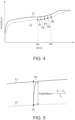
- FIG. 4 illustrates an example of a change in voltage of the battery 41 while the battery 41 is in charge.
- FIG. 5 is an enlarged diagram of a part of FIG. 4 .
- a horizontal axis of a graph indicates the SoC, and a vertical axis of the graph indicates a voltage.
- a line L1 indicates closed circuit voltages (CCV) of the battery 41 while the battery 41 is in charge.
- points P1 to P5 on a line L2 indicate open circuit voltages (OCV) of the battery 41 after the charging of the battery 41 is stopped for one minute.
- OCV open circuit voltages
- FIG. 5 illustrates the voltage of the battery 41 at the periphery of the point P1 in FIG. 4 .
- a point P0 on the line L1 illustrated in FIG. 5 indicates the voltage of the battery 41 in step S100.
- the state acquisition unit 440 acquires the voltage value V1 and the current value I1 at the point P0.
- the point P1 on the line L2 illustrated in FIG. 5 indicates the voltage of the battery 41 in step S103.
- the state acquisition unit 440 acquires the voltage value V2 at the point P1.
- the impedance value calculation unit 441 calculates the impedance value of the battery 41 by dividing a difference (V1 - V2) between the voltage value V1 and the voltage value V2 by the current value I1. In addition, the impedance value calculation unit 441 calculates the corrected impedance value by multiplying the impedance value by the correction coefficient according to the temperature T.
- FIG. 6 illustrates an example of an impedance of a battery configured in the same manner as the battery 41.
- a horizontal axis of a graph indicates a voltage of the battery when the SoC is 60%, and a vertical axis of the graph indicates an impedance of the battery.
- a line L3 in FIG. 6 indicates the impedance at the temperature of 45°C.
- a line L4 in FIG. 6 indicates the impedance at the temperature of 35°C.
- Line L5 in FIG. 6 indicates the impedance at the temperature of 25°C.
- a line L6 in FIG. 6 indicates the impedance at the temperature of 15°C.
- the same processing as the processing of steps S101 to S103 is executed, and the impedance value is calculated.
- the impedance values at various temperatures are calculated, and data of the graph illustrated in FIG. 6 is obtained.
- the correction coefficient according to the temperature is calculated by using the data.
- FIG. 7 illustrates an example of the correction coefficient.
- a reference temperature is 25°C, and the correction coefficient at the reference temperature is set to 1.00.
- the correction coefficient at each temperature other than the reference temperature is a ratio of the impedance value at each temperature to the impedance value at the reference temperature.
- the correction coefficient illustrated in FIG. 7 is recorded in the memory 45 in advance.
- the correction coefficient increases as the temperature is increased. For example, when the temperature is the reference temperature (25°C), the impedance value calculation unit 441 multiplies the impedance value by a predetermined correction coefficient (1.00). When the temperature is lower than the reference temperature, the impedance value calculation unit 441 multiplies the correction coefficient, which is smaller than the predetermined correction coefficient, by the impedance value. When the temperature is higher than the reference temperature, the impedance value calculation unit 441 multiplies the correction coefficient, which is larger than the predetermined correction coefficient, by the impedance value.
- step S104 the memory control unit 443 records the corrected impedance value in the memory 45.
- the memory control unit 443 may update the corrected impedance value recorded in the memory 45 last time, with the newly calculated corrected impedance value.
- the memory control unit 443 may record the newly calculated corrected impedance value in the memory 45 in a state of being identifiable from the corrected impedance value calculated in the past. After that, the controller 44 executes step S100 again.
- FIG. 8 illustrates an example of the capacity calculation process according to the present embodiment.
- the controller 44 executes the capacity calculation process illustrated in FIG. 8 at any time.
- the controller 44 may execute the capacity calculation process while the battery 41 is in charge or may execute the capacity calculation process when the battery 41 is not being charged.
- the memory control unit 443 determines whether or not the new corrected impedance value is recorded in the memory 45 each time the predetermined time elapses. When the new corrected impedance value is not recorded in the memory 45, the controller 44 executes step S200 again. When the new corrected impedance value is recorded in the memory 45, the controller 44 executes the following step S201.
- the battery capacity calculation unit 442 calculates a corrected impedance growth.
- the corrected impedance growth is a ratio of the corrected impedance value, which is recorded in the memory 45, to an initial impedance value.
- the initial impedance value is an impedance value of the battery 41 before the use of the battery 41 is started (before the first charging of the battery 41 is started).
- the impedance value of the battery 41 is gradually increased from the initial impedance value as time elapses.
- the initial impedance value is recorded in the memory 45 in advance.
- the state acquisition unit 440 acquires information related to the number of cycles and high temperature-high pressure time from the BMU 42.
- One cycle corresponds to a period during when the state of the battery 41 changes from a completely discharged state to a fully charged state and then returns to the completely discharged state.
- the battery 41 stores the number of cycles, which is from a time point when the use of the battery 41 is started, inside the battery 41.
- the high temperature-high pressure time is time (hour) until the temperature of the battery 41 falls within a predetermined temperature range and an output voltage value of the battery 41 falls within a predetermined voltage range.
- the predetermined temperature range is 45°C or higher and 70°C or lower.
- the predetermined voltage range is 4.4 V or more and 4.5 V or less.
- step S202 the battery capacity calculation unit 442 calculates the full charge capacity of the battery 41 by using the number of cycles, the high temperature-high pressure time, and the corrected impedance growth.
- the memory control unit 443 records the full charge capacity in the memory 45. After that, the controller 44 executes step S200 again.
- FIG. 9 illustrates an example of a relationship between the number of cycles and a capacity retention rate and a relationship between the number of cycles and an impedance growth.
- the capacity retention rate is obtained by dividing the design capacity by the full charge capacity.
- the impedance growth is a ratio of the current impedance value to the initial impedance value.
- a horizontal axis of a graph indicates the number of cycles, and a vertical axis of the graph indicates the capacity retention rate and the impedance growth.
- a line L10 illustrated in FIG. 9 indicates a relationship between the number of cycles and the capacity retention rate.
- a line L11 illustrated in FIG. 9 indicates a relationship between the number of cycles and the impedance growth.
- FIG. 10 illustrates an example of a relationship between the impedance growth and the capacity retention rate of the battery configured in the same manner as the battery 41.
- a horizontal axis of a graph indicates the impedance growth
- a vertical axis of the graph indicates the capacity retention rate.
- the graph in FIG. 10 is a measurement result of the impedance and the full charge capacity obtained by deteriorating the battery in three different test environments, and respective test environment temperatures are 25°C, 45°C, and 60°C. As illustrated in FIG. 10 , it is presumed that the relationship between the impedance and the full charge capacity can be approximated with a straight line.
- FIG. 11 illustrates three straight lines that approximate the measurement results illustrated in FIG. 10 .
- the straight line L7 approximates the measurement result in a deterioration mode 1 (test environment temperature of 25°C).
- the straight line L8 approximates the measurement result in a deterioration mode 2 (test environment temperature of 45°C).
- the straight line L9 approximates the measurement result in a deterioration mode 3 (test environment temperature of 60°C).
- the relationship between the impedance and the full charge capacity can be approximated with a straight line, and the relationship depends on the temperature.
- the relationship between the number of cycles and the capacity retention rate can be approximated with a straight line.
- the full charge capacity FCC of the battery 41 is represented by the following Expression (1) using the number of cycles CYC, the high temperature-high pressure time HTVT, and the corrected impedance growth IMP.
- FCC 1.0 + a * CYC + b * HTVT + c * IMP
- a, b, and c in Expression (1) are predetermined coefficients.
- the impedance value and the full charge capacity at various temperatures are measured, and the number of cycles and the high temperature-high pressure time are acquired.
- the least squares method is applied, and the coefficient a, the coefficient b, and the coefficient c are calculated.
- These coefficients are stored in the memory 45 in advance.
- the controller 44 calculates the full charge capacity by using Expression (1) .
- the controller 44 acquires a first voltage value (V1) and a charge current value (I1) of the battery 41 while the battery 41 is in charge.
- the controller 44 acquires a second voltage value (V2) of the battery 41 while charging of the battery 41 is in pause.
- the controller 44 calculates the impedance value of the battery 41 by using the first voltage value, the second voltage value, and the charge current value.
- the controller 44 calculates the impedance growth, which is a ratio of the impedance value to the initial impedance value recorded in the memory 45 in advance.
- the controller 44 acquires the number of cycles of the battery 41.
- the controller 44 acquires time (high temperature-high pressure time) until the temperature of the battery 41 falls within the predetermined temperature range and the output voltage value of the battery 41 falls within the predetermined voltage range.
- the controller 44 calculates the full charge capacity of the battery 41 by using the number of cycles, the impedance growth, and the high temperature-high pressure time.
- the controller 44 is capable of calculating the full charge capacity at a high frequency.
- the controller 44 calculates the full charge capacity according to Expression (1).
- the controller 44 is capable of calculating the full charge capacity by using a simple expression.
- the controller 44 may calculate the full charge capacity without using the high temperature-high pressure time. In this case, the controller 44 does not need to acquire the high temperature-high pressure time from the BMU 42.
- the controller 44 calculates the full charge capacity by using the following Expression (2) obtained by modifying Expression (1).
- FCC 1.0 + a * CYC + c * IMP
- the controller 44 corrects the impedance value according to the temperature while the battery 41 is in charge.
- the controller 44 calculates the full charge capacity by using the corrected impedance growth according to the temperature. Therefore, the controller 44 is capable of calculating the full charge capacity with high accuracy.
- FIG. 12 illustrates an example of a configuration of the battery 40a according to the present embodiment. Only a configuration different from the configuration illustrated in FIG. 2 will be described, and the description of the configuration having the same configuration as the configuration illustrated in FIG. 2 will be omitted.
- a battery capacity calculation device 43a illustrated in FIG. 12 is used instead of the battery capacity calculation device 43 illustrated in FIG. 2 .
- a controller 44a is used instead of the controller 44 illustrated in FIG. 2 .
- the controller 44a includes a lifetime estimation unit 445 in addition to the state acquisition unit 440, the impedance value calculation unit 441, the battery capacity calculation unit 442, the memory control unit 443, and the charge control unit 444 illustrated in FIG. 2 .
- the lifetime estimation unit 445 calculates time during when the full charge capacity of the battery 41 is equal to or less than a predetermined capacity.
- the controller 44a executes a capacity calculation process illustrated in FIG. 13 instead of the capacity calculation process illustrated in FIG. 8 .
- FIG. 13 illustrates an example of the capacity calculation process according to the present embodiment. Only the processing different from the processing illustrated in FIG. 8 will be described, and the description of the processing the same as the processing illustrated in FIG. 8 will be omitted.
- Steps S200 to S203 illustrated in FIG. 13 are the same as steps S200 to S203 illustrated in FIG. 8 .
- the lifetime estimation unit 445 determines whether or not the full charge capacity (FCC), which is calculated in step S203, is less than 80%. When the full charge capacity is 80% or more, the controller 44a executes step S200. When the full charge capacity is less than 80%, the controller 44a executes step S205.
- FCC full charge capacity
- the full charge capacity calculated in step S203 and the time information indicating the date on which the full charge capacity is calculated are recorded in the memory 45.
- the lifetime estimation unit 445 calculates the time during when the full charge capacity reaches a reference capacity, by using the full charge capacity and the time information recorded in the memory 45.
- FIG. 14 illustrates an example of a time change in full charge capacity of the battery configured in the same manner as the battery 41.
- a horizontal axis of a graph indicates the time
- a vertical axis indicates the full charge capacity.
- the full charge capacity is gradually decreased as time elapses. A relationship between the time and the full charge capacity can be approximated with a straight line.
- the full charge capacity is 80% on the day indicated by T1. Thereafter, the full charge capacity is 60% of the reference capacity on the date indicated by T2.
- the lifetime estimation unit 445 calculates the time between T1 and T2.
- the lifetime estimation unit 445 calculates an approximate straight line expression indicating the relationship between the time and the full charge capacity by using the past full charge capacity recorded in the memory 45.
- the lifetime estimation unit 445 calculates the time during when the full charge capacity is changed from 80% to 60% by using the expression. This time serves as a guideline for when the user should replace the battery 41.
- the lifetime estimation unit 445 may calculate the number of cycles corresponding to the time.
- a threshold value in step S204 is 80%
- the threshold value may be a value other than 80%.
- the reference capacity is 60%
- the reference capacity may be a value other than 60%.
- the time which is calculated by the lifetime estimation unit 445, may be output to the CPU 11.
- the CPU 11 may execute a notification process of notifying the user of the time. For example, the CPU 11 may display the information indicating the time on the display unit 14. The CPU 11 may cause a speaker (not illustrated in FIG. 1 ) to generate an audio corresponding to the information. The CPU 11 may transmit the information to other apparatuses via the WLAN card 25.
- the controller 44 records the calculated full charge capacity and the time information at a time point when the full charge capacity is calculated, in the memory 45.
- the controller 44 calculates the time during when the full charge capacity of the battery 41 is equal to or less than the predetermined capacity, by using the full charge capacity and the time information recorded in the memory 45.
- the controller 44 is capable of predicting a lifetime of the battery 41.
Landscapes
- Physics & Mathematics (AREA)
- General Physics & Mathematics (AREA)
- Engineering & Computer Science (AREA)
- Life Sciences & Earth Sciences (AREA)
- Sustainable Development (AREA)
- Sustainable Energy (AREA)
- Power Engineering (AREA)
- Transportation (AREA)
- Mechanical Engineering (AREA)
- Charge And Discharge Circuits For Batteries Or The Like (AREA)
- Secondary Cells (AREA)
- Tests Of Electric Status Of Batteries (AREA)
Abstract
Description
- The present invention relates to a battery capacity calculation device and a battery capacity calculation method.
- Developing products that users can use for a long period of time leads to reduce carbon emissions. It is expected that the amount of electronic waste (E-waste) is reduced and environmental problems are improved by having users replace batteries of electronic apparatuses, such as laptop personal computers (PCs) in a timely manner. Therefore, there is a demand for a function of prompting a user to replace a battery in a timely manner.
- As a function for notifying the user of the deterioration degree of the battery, there is a function of estimating a state of the battery based on a capacity retention rate and the number of cycles and displaying the state. The capacity retention rate is obtained by dividing a full charge capacity (FCC) by a design capacity. In addition, a related art is known in which a full charge capacity is calculated based on a current value from a fully charged state of the battery to a completely discharged state.
- A device disclosed in
Japanese Unexamined Patent Application Publication No. 2021-125320 - In the related art of estimating a full charge capacity, it is necessary to completely discharge the battery, and thus the calculation frequency of the full charge capacity is low.
- An object of the present invention is to provide a battery capacity calculation device and a battery capacity calculation method capable of calculating a full charge capacity at a high frequency.
- A battery capacity calculation device according to a first aspect of the present invention includes: a controller, in which the controller is configured to acquire, while a battery is in charge, a first voltage value and a charge current value of the battery, acquire, while charging of the battery is in pause, a second voltage value of the battery, calculate an impedance value of the battery by using the first voltage value, the second voltage value, and the charge current value, calculate an impedance growth that is a ratio of the impedance value to an initial impedance value recorded in a memory in advance, acquire the number of cycles of the battery, acquire time until a temperature of the battery falls within a predetermined temperature range and an output voltage value of the battery falls within a predetermined voltage range, and calculate a full charge capacity of the battery by using the number of cycles, the impedance growth, and the time.
- According to the first aspect of the present invention, the controller may be configured to calculate the full charge capacity according to an expression: FCC = 1.0 + a * CYC + b * HTVT + c * IMP, and in the expression, FCC is the full charge capacity, CYC is the number of cycles, HTVT is the time, IMP is the impedance growth, and a, b, and c are predetermined coefficients.
- According to the first aspect of the present invention, the controller may be configured to correct the impedance value according to the temperature of the battery while the battery is in charge.
- According to the first aspect of the present invention, the controller may be configured to record the calculated full charge capacity and time information at a time point when the full charge capacity is calculated, in a memory, and calculate time during when the full charge capacity of the battery is equal to or less than a predetermined capacity, by using the full charge capacity and the time information recorded in the memory.
- A battery capacity calculation device according to a second aspect of the present invention includes: a controller, in which the controller is configured to acquire, while a battery is in charge, a first voltage value and a charge current value of the battery, acquire, while charging of the battery is in pause, a second voltage value of the battery, calculate an impedance value of the battery by using the first voltage value, the second voltage value, and the charge current value, calculate an impedance growth that is a ratio of the impedance value to an initial impedance value recorded in a memory in advance, acquire the number of cycles of the battery, and calculate a full charge capacity of the battery by using the number of cycles and the impedance growth.
- A battery capacity calculation method according to a third aspect of the present invention includes: a step of acquiring, while a battery is in charge, a first voltage value and a charge current value of the battery; a step of acquiring, while charging of the battery is in pause, a second voltage value of the battery; a step of calculating an impedance value of the battery by using the first voltage value, the second voltage value, and the charge current value; a step of calculating an impedance growth that is a ratio of the impedance value to an initial impedance value recorded in a memory in advance; a step of acquiring the number of cycles of the battery; a step of acquiring time until a temperature of the battery falls within a predetermined temperature range and an output voltage value of the battery falls within a predetermined voltage range; and a step of calculating a full charge capacity of the battery by using the number of cycles, the impedance growth, and the time.
- A battery capacity calculation method according to a fourth aspect of the present invention includes: a step of acquiring, while a battery is in charge, a first voltage value and a charge current value of the battery; a step of acquiring, while charging of the battery is in pause, a second voltage value of the battery; a step of calculating an impedance value of the battery by using the first voltage value, the second voltage value, and the charge current value; a step of calculating an impedance growth that is a ratio of the impedance value to an initial impedance value recorded in a memory in advance; a step of acquiring the number of cycles of the battery; and a step of calculating a full charge capacity of the battery by using the number of cycles and the impedance growth.
- The battery capacity calculation device and the battery capacity calculation method of present invention can calculate a full charge capacity at a high frequency.
-
-
FIG. 1 is a block diagram illustrating a configuration example of hardware of an electronic apparatus according to a first embodiment of the present invention. -
FIG. 2 is a block diagram illustrating an example of a configuration of a battery according to the first embodiment of the present invention. -
FIG. 3 is a flowchart illustrating an example of an impedance value calculation process according to the first embodiment of the present invention. -
FIG. 4 is a diagram illustrating an example of a change in voltage of a battery according to the first embodiment of the present invention. -
FIG. 5 is a diagram illustrating an example of a change in voltage of the battery according to the first embodiment of the present invention. -
FIG. 6 is a diagram illustrating an example of an impedance of the battery according to the first embodiment of the present invention. -
FIG. 7 is a diagram illustrating an example of a correction coefficient according to the first embodiment of the present invention. -
FIG. 8 is a flowchart illustrating an example of a capacity calculation process according to the first embodiment of the present invention. -
FIG. 9 illustrates an example of a relationship between the number of cycles and a capacity retention rate and a relationship between the number of cycles and an impedance growth according to the first embodiment of the present invention. -
FIG. 10 is a diagram illustrating an example of a relationship between the impedance growth and the capacity retention rate of the battery according to the first embodiment of the present invention. -
FIG. 11 is a diagram illustrating an example of a relationship between the impedance growth and the capacity retention rate of the battery according to the first embodiment of the present invention. -
FIG. 12 is a block diagram illustrating an example of a configuration of the battery according to a second embodiment of the present invention. -
FIG. 13 is a flowchart illustrating an example of the capacity calculation process according to the second embodiment of the present invention. -
FIG. 14 is a diagram illustrating an example of a time change in full charge capacity of the second embodiment of the present invention. - Hereinafter, an embodiment of the present invention will be described with reference to the drawings.
- A first embodiment of the present invention will be described.
FIG. 1 is a block diagram illustrating an example of a hardware configuration of anelectronic apparatus 10 according to the present embodiment. - The
electronic apparatus 10 includes aCPU 11, amain memory 12, avideo subsystem 13, adisplay unit 14, achipset 21, aBIOS memory 22, astorage medium 23, anaudio system 24, aWLAN card 25, aUSB connector 26, embeddedcontroller 31, aninput unit 32, apower supply circuit 33, and abattery 40. - The
CPU 11 executes various types of arithmetic processing with program control and controls the entireelectronic apparatus 10. For example, theCPU 11 executes processing based on programs of an operating system (OS) and a basic input output system (BIOS). TheCPU 11 is an example of a processor. - The
main memory 12 is a writable memory used as a read area for an execution program of theCPU 11 or as a work area for writing processing data of the execution program. Themain memory 12 includes, for example, a plurality of dynamic random access memory (DRAM) chips. This execution program includes an OS, various drivers for operating peripheral equipment, various services/utilities, an application program, and the like. - The
video subsystem 13 is a subsystem for realizing a function related to image display and includes a video controller. The video controller processes a drawing instruction from theCPU 11, writes the processed drawing information to the video memory, reads the drawing information from the video memory, and outputs the drawing information as drawing data (display data) to thedisplay unit 14. - The
display unit 14 is, for example, a liquid crystal display or an organic EL display, and displays a display screen based on the drawing data (display data) output from thevideo subsystem 13. - The
chipset 21 includes a controller for a universal serial bus (USB), a serial AT attachment (ATA), a serial peripheral interface (SPI) bus, a peripheral component interconnect (PCI) bus, a PCI-Express bus, low pin count (LPC) bus, and the like, and a plurality of devices is connected to thechipset 21. For example, theBIOS memory 22, thestorage medium 23, theaudio system 24, theWLAN card 25, theUSB connector 26, and the embeddedcontroller 31, which are described later, are included as a plurality of devices. - The
BIOS memory 22 includes an electrically rewritable non-volatile memory such as an electrically erasable programmable read only memory (EEPROM) or a flash ROM. TheBIOS memory 22 stores, for example, a program of a BIOS, a system firmware for controlling the embeddedcontroller 31, and the like. TheBIOS memory 22 is an example of a sub memory. - The
storage medium 23 includes a hard disk drive (HDD), a solid state drive (SSD), and the like. For example, thestorage medium 23 stores an OS, various drivers, various services/utilities, an application program, and various data. - A microphone and a speaker (not illustrated) are connected to the
audio system 24, and theaudio system 24 records, plays, and outputs sound data. The microphone and the speaker are built in theelectronic apparatus 10 as an example. - The wireless local area network (WLAN)
card 25 is connected to a network by a wireless LAN, and performs data communication. For example, when theWLAN card 25 receives data from the network, theWLAN card 25 generates an event trigger indicating that the data has been received. TheUSB connector 26 is a connector for connecting peripheral equipment using USB. - The
input unit 32 collectively indicates input devices (input equipment) included in theelectronic apparatus 10. The input device, which is included in theinput unit 32, outputs input information input by a user's operation to the embeddedcontroller 31. - The
power supply circuit 33 includes, for example, a DC/DC converter, a charge/discharge unit, an AC/DC adapter, and the like. For example, thepower supply circuit 33 converts a direct current voltage supplied from an external power supply such as an AC adapter (not illustrated) or thebattery 40 into a plurality of voltages required for operating theelectronic apparatus 10. In addition, thepower supply circuit 33 supplies electric power to each unit of theelectronic apparatus 10 based on the control from the embeddedcontroller 31. - The
battery 40 is a secondary battery such as a lithium-ion battery, for example. When the electric power is supplied to theelectronic apparatus 10 from an external power supply, thebattery 40 is charged via thepower supply circuit 33. When the electric power is not supplied to theelectronic apparatus 10 from an external power supply, thebattery 40 outputs the accumulated electric power as operating power of theelectronic apparatus 10 via thepower supply circuit 33. - The embedded
controller 31 is a one-chip microcomputer that monitors and controls various devices (peripheral devices, sensors, and the like) regardless of a state of a system of theelectronic apparatus 10. The embeddedcontroller 31 includes a CPU, a ROM, a RAM, a plurality of channels of A/D input terminals and a D/A output terminal, a timer, and a digital input/output terminal, which are not illustrated. Theinput unit 32, thepower supply circuit 33, and the like are connected to the digital input/output terminal of the embeddedcontroller 31, and the embeddedcontroller 31 controls operations thereof. In addition, the embeddedcontroller 31 performs control such as a change in clock frequency of theCPU 11 via thechipset 21. -
FIG. 2 illustrates an example of a configuration of thebattery 40 according to the present embodiment. Thebattery 40 includes abattery 41, a battery management unit (BMU) 42, and a batterycapacity calculation device 43. The batterycapacity calculation device 43 may be included in theBMU 42. - For example, the
battery 41 is a lithium ion battery. TheBMU 42 monitors various states of thebattery 41 and acquires information related to various states from thebattery 41. For example, theBMU 42 acquires a voltage value, a current value, a temperature, and the like of thebattery 41 from thebattery 41. - The battery
capacity calculation device 43 includes acontroller 44 and amemory 45. Thecontroller 44 includes a micro processing unit (MPU) or the like. Thememory 45 includes a storage medium, such as a RAM. - The
controller 44 includes astate acquisition unit 440, an impedancevalue calculation unit 441, a batterycapacity calculation unit 442, amemory control unit 443, and acharge control unit 444 as a functional configuration of processing executed by the MPU. The function of thecontroller 44 may be implemented in a battery firmware. - The
state acquisition unit 440 acquires information related to various states of thebattery 41 from theBMU 42. The impedancevalue calculation unit 441 calculates an impedance value of thebattery 41 by using the information acquired from theBMU 42. The batterycapacity calculation unit 442 calculates a full charge capacity of thebattery 41 by using the information acquired from theBMU 42 and the impedance value calculated by the impedancevalue calculation unit 441. Thememory control unit 443 controls the reading and writing of data between thecontroller 44 and thememory 45. Thecharge control unit 444 controls the charging of thebattery 41 via theBMU 42. - An impedance value calculation process executed by the
controller 44 will be described with reference toFIG. 3. FIG. 3 illustrates an example of the impedance value calculation process according to the present embodiment. Thecontroller 44 executes the impedance value calculation process illustrated inFIG. 3 while thebattery 41 is in charge. - The
state acquisition unit 440 acquires information related to a state of charge (SoC) of thebattery 41 from theBMU 42 each time a predetermined time elapses. The SoC indicates a charging state of thebattery 41. When thebattery 41 is in a fully charged state, the SoC is 100%, and when thebattery 41 is in a completely discharged state, the SoC is 0%. Thestate acquisition unit 440 determines whether or not the charging state indicated by the SoC is a predetermined state. The predetermined state corresponds to a state in which theelectronic apparatus 10 is in operation by receiving electric power from thebattery 41 and the impedance of thebattery 41 is stable. For example, the predetermined state corresponds to 60%, 65%, 70%, 75%, or 80% of the SoC. - When the charging state of the
battery 41 is not the predetermined state, thecontroller 44 executes step S100 again. When the charging state of thebattery 41 is the predetermined state, thecontroller 44 executes the following step S101. - When the SoC is 60%, 65%, 70%, 75%, or 80%, the
controller 44 calculates the impedance value of thebattery 41 as follows. Therefore, thecontroller 44 is capable of calculating the impedance value of thebattery 41 at a high frequency. - The
state acquisition unit 440 acquires information related to a voltage value V1, a current value I1, and a temperature T of thebattery 41 from theBMU 42. - After step S101 is executed, the
charge control unit 444 stops the charging of thebattery 41 for one minute. The time during when thecharge control unit 444 stops the charging is not limited to one minute. - After step S102 is executed, the
state acquisition unit 440 acquires information related to a voltage value V2 of thebattery 41 from theBMU 42. - After step S103 is executed, the impedance
value calculation unit 441 calculates the impedance value of thebattery 41 by using the voltage value V1, the voltage value V2, and the current value I1. In addition, the impedancevalue calculation unit 441 corrects the impedance value by using the temperature T and obtains a corrected impedance value. - A method of calculating the impedance value of the
battery 41 by the impedancevalue calculation unit 441 will be described with reference toFIGS. 4 and 5. FIG. 4 illustrates an example of a change in voltage of thebattery 41 while thebattery 41 is in charge.FIG. 5 is an enlarged diagram of a part ofFIG. 4 . - In
FIG. 4 , a horizontal axis of a graph indicates the SoC, and a vertical axis of the graph indicates a voltage. InFIG. 4 , a line L1 indicates closed circuit voltages (CCV) of thebattery 41 while thebattery 41 is in charge. InFIG. 4 , points P1 to P5 on a line L2 indicate open circuit voltages (OCV) of thebattery 41 after the charging of thebattery 41 is stopped for one minute. When the SoC is 60%, the open circuit voltage of thebattery 41 is at the point P1. When the SoC is 65%, the open circuit voltage of thebattery 41 is at the point P2. When the SoC is 70%, the open circuit voltage of thebattery 41 is at the point P3. When the SoC is 75%, the open circuit voltage of thebattery 41 is at the point P4. When the SoC is 80%, the open circuit voltage of thebattery 41 is at the point P5. -
FIG. 5 illustrates the voltage of thebattery 41 at the periphery of the point P1 inFIG. 4 . A point P0 on the line L1 illustrated inFIG. 5 indicates the voltage of thebattery 41 in step S100. Thestate acquisition unit 440 acquires the voltage value V1 and the current value I1 at the point P0. The point P1 on the line L2 illustrated inFIG. 5 indicates the voltage of thebattery 41 in step S103. Thestate acquisition unit 440 acquires the voltage value V2 at the point P1. - The impedance
value calculation unit 441 calculates the impedance value of thebattery 41 by dividing a difference (V1 - V2) between the voltage value V1 and the voltage value V2 by the current value I1. In addition, the impedancevalue calculation unit 441 calculates the corrected impedance value by multiplying the impedance value by the correction coefficient according to the temperature T. -
FIG. 6 illustrates an example of an impedance of a battery configured in the same manner as thebattery 41. InFIG. 6 , a horizontal axis of a graph indicates a voltage of the battery when the SoC is 60%, and a vertical axis of the graph indicates an impedance of the battery. A line L3 inFIG. 6 indicates the impedance at the temperature of 45°C. A line L4 inFIG. 6 indicates the impedance at the temperature of 35°C. Line L5 inFIG. 6 indicates the impedance at the temperature of 25°C. A line L6 inFIG. 6 indicates the impedance at the temperature of 15°C. - For example, by using the battery configured in the same manner as the
battery 40, the same processing as the processing of steps S101 to S103 is executed, and the impedance value is calculated. The impedance values at various temperatures are calculated, and data of the graph illustrated inFIG. 6 is obtained. The correction coefficient according to the temperature is calculated by using the data. -
FIG. 7 illustrates an example of the correction coefficient. In this example, a reference temperature is 25°C, and the correction coefficient at the reference temperature is set to 1.00. The correction coefficient at each temperature other than the reference temperature is a ratio of the impedance value at each temperature to the impedance value at the reference temperature. The correction coefficient illustrated inFIG. 7 is recorded in thememory 45 in advance. - The correction coefficient increases as the temperature is increased. For example, when the temperature is the reference temperature (25°C), the impedance
value calculation unit 441 multiplies the impedance value by a predetermined correction coefficient (1.00). When the temperature is lower than the reference temperature, the impedancevalue calculation unit 441 multiplies the correction coefficient, which is smaller than the predetermined correction coefficient, by the impedance value. When the temperature is higher than the reference temperature, the impedancevalue calculation unit 441 multiplies the correction coefficient, which is larger than the predetermined correction coefficient, by the impedance value. - After step S104 is executed, the
memory control unit 443 records the corrected impedance value in thememory 45. Thememory control unit 443 may update the corrected impedance value recorded in thememory 45 last time, with the newly calculated corrected impedance value. Thememory control unit 443 may record the newly calculated corrected impedance value in thememory 45 in a state of being identifiable from the corrected impedance value calculated in the past. After that, thecontroller 44 executes step S100 again. - A description of the capacity calculation process executed by the
controller 44 will be made with reference toFIG. 8. FIG. 8 illustrates an example of the capacity calculation process according to the present embodiment. Thecontroller 44 executes the capacity calculation process illustrated inFIG. 8 at any time. Thecontroller 44 may execute the capacity calculation process while thebattery 41 is in charge or may execute the capacity calculation process when thebattery 41 is not being charged. - The
memory control unit 443 determines whether or not the new corrected impedance value is recorded in thememory 45 each time the predetermined time elapses. When the new corrected impedance value is not recorded in thememory 45, thecontroller 44 executes step S200 again. When the new corrected impedance value is recorded in thememory 45, thecontroller 44 executes the following step S201. - The battery
capacity calculation unit 442 calculates a corrected impedance growth. The corrected impedance growth is a ratio of the corrected impedance value, which is recorded in thememory 45, to an initial impedance value. The initial impedance value is an impedance value of thebattery 41 before the use of thebattery 41 is started (before the first charging of thebattery 41 is started). The impedance value of thebattery 41 is gradually increased from the initial impedance value as time elapses. The initial impedance value is recorded in thememory 45 in advance. - The
state acquisition unit 440 acquires information related to the number of cycles and high temperature-high pressure time from theBMU 42. - One cycle corresponds to a period during when the state of the
battery 41 changes from a completely discharged state to a fully charged state and then returns to the completely discharged state. Thebattery 41 stores the number of cycles, which is from a time point when the use of thebattery 41 is started, inside thebattery 41. - The high temperature-high pressure time is time (hour) until the temperature of the
battery 41 falls within a predetermined temperature range and an output voltage value of thebattery 41 falls within a predetermined voltage range. For example, the predetermined temperature range is 45°C or higher and 70°C or lower. For example, the predetermined voltage range is 4.4 V or more and 4.5 V or less. - After step S202 is executed, the battery
capacity calculation unit 442 calculates the full charge capacity of thebattery 41 by using the number of cycles, the high temperature-high pressure time, and the corrected impedance growth. Thememory control unit 443 records the full charge capacity in thememory 45. After that, thecontroller 44 executes step S200 again. - An example of a method of calculating the full charge capacity of the
battery 41 will be described.FIG. 9 illustrates an example of a relationship between the number of cycles and a capacity retention rate and a relationship between the number of cycles and an impedance growth. As described above, the capacity retention rate is obtained by dividing the design capacity by the full charge capacity. The impedance growth is a ratio of the current impedance value to the initial impedance value. - In
FIG. 9 , a horizontal axis of a graph indicates the number of cycles, and a vertical axis of the graph indicates the capacity retention rate and the impedance growth. A line L10 illustrated inFIG. 9 indicates a relationship between the number of cycles and the capacity retention rate. A line L11 illustrated inFIG. 9 indicates a relationship between the number of cycles and the impedance growth. As illustrated inFIG. 9 , as the number of cycles is increased, the capacity retention rate is decreased and the impedance growth is increased. That is, as the impedance is increased, the full charge capacity is decreased. The batterycapacity calculation unit 442 calculates the full charge capacity based on a relationship between the full charge capacity and the impedance. -
FIG. 10 illustrates an example of a relationship between the impedance growth and the capacity retention rate of the battery configured in the same manner as thebattery 41. InFIG. 10 , a horizontal axis of a graph indicates the impedance growth, and a vertical axis of the graph indicates the capacity retention rate. - The graph in
FIG. 10 is a measurement result of the impedance and the full charge capacity obtained by deteriorating the battery in three different test environments, and respective test environment temperatures are 25°C, 45°C, and 60°C. As illustrated inFIG. 10 , it is presumed that the relationship between the impedance and the full charge capacity can be approximated with a straight line. -
FIG. 11 illustrates three straight lines that approximate the measurement results illustrated inFIG. 10 . The straight line L7 approximates the measurement result in a deterioration mode 1 (test environment temperature of 25°C). The straight line L8 approximates the measurement result in a deterioration mode 2 (test environment temperature of 45°C). The straight line L9 approximates the measurement result in a deterioration mode 3 (test environment temperature of 60°C). - As illustrated in
FIG. 11 , the relationship between the impedance and the full charge capacity can be approximated with a straight line, and the relationship depends on the temperature. In addition, as illustrated inFIG. 9 , the relationship between the number of cycles and the capacity retention rate can be approximated with a straight line. In consideration of these, the full charge capacity FCC of thebattery 41 is represented by the following Expression (1) using the number of cycles CYC, the high temperature-high pressure time HTVT, and the corrected impedance growth IMP.
- Where, a, b, and c in Expression (1) are predetermined coefficients. By using the battery configured in the same manner as the
battery 41, the impedance value and the full charge capacity at various temperatures are measured, and the number of cycles and the high temperature-high pressure time are acquired. As a result, for example, the least squares method is applied, and the coefficient a, the coefficient b, and the coefficient c are calculated. These coefficients are stored in thememory 45 in advance. Thecontroller 44 calculates the full charge capacity by using Expression (1) . - As described above, the
controller 44 acquires a first voltage value (V1) and a charge current value (I1) of thebattery 41 while thebattery 41 is in charge. Thecontroller 44 acquires a second voltage value (V2) of thebattery 41 while charging of thebattery 41 is in pause. Thecontroller 44 calculates the impedance value of thebattery 41 by using the first voltage value, the second voltage value, and the charge current value. Thecontroller 44 calculates the impedance growth, which is a ratio of the impedance value to the initial impedance value recorded in thememory 45 in advance. Thecontroller 44 acquires the number of cycles of thebattery 41. Thecontroller 44 acquires time (high temperature-high pressure time) until the temperature of thebattery 41 falls within the predetermined temperature range and the output voltage value of thebattery 41 falls within the predetermined voltage range. Thecontroller 44 calculates the full charge capacity of thebattery 41 by using the number of cycles, the impedance growth, and the high temperature-high pressure time. - In the present embodiment, a charging amount and a discharging amount of the
battery 41 required for calculating the full charge capacity are small. Therefore, thecontroller 44 is capable of calculating the full charge capacity at a high frequency. - The
controller 44 calculates the full charge capacity according to Expression (1). Thecontroller 44 is capable of calculating the full charge capacity by using a simple expression. - The
controller 44 may calculate the full charge capacity without using the high temperature-high pressure time. In this case, thecontroller 44 does not need to acquire the high temperature-high pressure time from theBMU 42. Thecontroller 44 calculates the full charge capacity by using the following Expression (2) obtained by modifying Expression (1).
- The
controller 44 corrects the impedance value according to the temperature while thebattery 41 is in charge. Thecontroller 44 calculates the full charge capacity by using the corrected impedance growth according to the temperature. Therefore, thecontroller 44 is capable of calculating the full charge capacity with high accuracy. - A second embodiment of the present invention will be described. In the second embodiment, a
battery 40a illustrated inFIG. 12 is used instead of thebattery 40 illustrated inFIG. 2 .FIG. 12 illustrates an example of a configuration of thebattery 40a according to the present embodiment. Only a configuration different from the configuration illustrated inFIG. 2 will be described, and the description of the configuration having the same configuration as the configuration illustrated inFIG. 2 will be omitted. - A battery
capacity calculation device 43a illustrated inFIG. 12 is used instead of the batterycapacity calculation device 43 illustrated inFIG. 2 . In the batterycapacity calculation device 43a, acontroller 44a is used instead of thecontroller 44 illustrated inFIG. 2 . - The
controller 44a includes alifetime estimation unit 445 in addition to thestate acquisition unit 440, the impedancevalue calculation unit 441, the batterycapacity calculation unit 442, thememory control unit 443, and thecharge control unit 444 illustrated inFIG. 2 . Thelifetime estimation unit 445 calculates time during when the full charge capacity of thebattery 41 is equal to or less than a predetermined capacity. - The
controller 44a executes a capacity calculation process illustrated inFIG. 13 instead of the capacity calculation process illustrated inFIG. 8 .FIG. 13 illustrates an example of the capacity calculation process according to the present embodiment. Only the processing different from the processing illustrated inFIG. 8 will be described, and the description of the processing the same as the processing illustrated inFIG. 8 will be omitted. - Steps S200 to S203 illustrated in
FIG. 13 are the same as steps S200 to S203 illustrated inFIG. 8 . - After step S203 is executed, the
lifetime estimation unit 445 determines whether or not the full charge capacity (FCC), which is calculated in step S203, is less than 80%. When the full charge capacity is 80% or more, thecontroller 44a executes step S200. When the full charge capacity is less than 80%, thecontroller 44a executes step S205. - The full charge capacity calculated in step S203 and the time information indicating the date on which the full charge capacity is calculated are recorded in the
memory 45. Thelifetime estimation unit 445 calculates the time during when the full charge capacity reaches a reference capacity, by using the full charge capacity and the time information recorded in thememory 45. -
FIG. 14 illustrates an example of a time change in full charge capacity of the battery configured in the same manner as thebattery 41. InFIG. 14 , a horizontal axis of a graph indicates the time, and a vertical axis indicates the full charge capacity. - The full charge capacity is gradually decreased as time elapses. A relationship between the time and the full charge capacity can be approximated with a straight line. The full charge capacity is 80% on the day indicated by T1. Thereafter, the full charge capacity is 60% of the reference capacity on the date indicated by T2. The
lifetime estimation unit 445 calculates the time between T1 and T2. - Specifically, the
lifetime estimation unit 445 calculates an approximate straight line expression indicating the relationship between the time and the full charge capacity by using the past full charge capacity recorded in thememory 45. Thelifetime estimation unit 445 calculates the time during when the full charge capacity is changed from 80% to 60% by using the expression. This time serves as a guideline for when the user should replace thebattery 41. Thelifetime estimation unit 445 may calculate the number of cycles corresponding to the time. - In the above example, although a threshold value in step S204 is 80%, the threshold value may be a value other than 80%. In the above example, although the reference capacity is 60%, the reference capacity may be a value other than 60%.
- The time, which is calculated by the
lifetime estimation unit 445, may be output to theCPU 11. TheCPU 11 may execute a notification process of notifying the user of the time. For example, theCPU 11 may display the information indicating the time on thedisplay unit 14. TheCPU 11 may cause a speaker (not illustrated inFIG. 1 ) to generate an audio corresponding to the information. TheCPU 11 may transmit the information to other apparatuses via theWLAN card 25. - As described above, the
controller 44 records the calculated full charge capacity and the time information at a time point when the full charge capacity is calculated, in thememory 45. Thecontroller 44 calculates the time during when the full charge capacity of thebattery 41 is equal to or less than the predetermined capacity, by using the full charge capacity and the time information recorded in thememory 45. Thecontroller 44 is capable of predicting a lifetime of thebattery 41. - Although the embodiment of the present invention has been described in detail with reference to the drawings above, a specific configuration is not limited to the above-described embodiment, and includes design changes and the like within a range not deviating from the gist of the present invention.
-
- 10
- electronic apparatus
- 11
- CPU
- 12
- main memory
- 13
- video subsystem
- 14
- display unit
- 21
- chipset
- 22
- BIOS memory
- 23
- storage medium
- 24
- audio system
- 25
- WLAN card
- 26
- USB connector
- 31
- embedded controller
- 32
- input unit
- 33
- power supply circuit
- 40,
- 40a battery
- 41
- battery
- 42
- BMU
- 43, 43a
- battery capacity calculation device
- 44, 44a
- controller
- 45
- memory
- 440
- state acquisition unit
- 441
- impedance value calculation unit
- 442
- battery capacity calculation unit
- 443
- memory control unit
- 444
- charge control unit
- 445
- lifetime estimation unit
Claims (10)
- A battery capacity calculation device comprising:a controller,wherein the controller is configured toacquire, while a battery is in charge, a first voltage value and a charge current value of the battery,acquire, while charging of the battery is in pause, a second voltage value of the battery,calculate an impedance value of the battery by using the first voltage value, the second voltage value, and the charge current value,calculate an impedance growth that is a ratio of the impedance value to an initial impedance value recorded in a memory in advance,acquire the number of cycles of the battery, andcalculate a full charge capacity of the battery by using the number of cycles and the impedance growth.
- The battery capacity calculation device according to claim 1, wherein the controller is further configured toacquire time until a temperature of the battery falls within a predetermined temperature range and an output voltage value of the battery falls within a predetermined voltage range, andcalculate the full charge capacity of the battery by using the number of cycles, the impedance growth, and the time.
- The battery capacity calculation device according to claim 2,wherein the controller is configured to calculate the full charge capacity according to an expression: FCC = 1.0 + a * CYC + b * HTVT + c * IMP, andin the expression, FCC is the full charge capacity, CYC is the number of cycles, HTVT is the time, IMP is the impedance growth, and a, b, and c are predetermined coefficients.
- The battery capacity calculation device according to claim 2 or 3,
wherein the controller is configured to correct the impedance value according to the temperature of the battery while the battery is in charge. - The battery capacity calculation device according to claim 2 or 3,
wherein the controller is configured torecord the calculated full charge capacity and time information at a time point when the full charge capacity is calculated, in a memory, andcalculate time during when the full charge capacity of the battery is equal to or less than a predetermined capacity, by using the full charge capacity and the time information recorded in the memory. - A battery capacity calculation method comprising:a step of acquiring, while a battery is in charge, a first voltage value and a charge current value of the battery;a step of acquiring, while charging of the battery is in pause, a second voltage value of the battery;a step of calculating an impedance value of the battery by using the first voltage value, the second voltage value, and the charge current value;a step of calculating an impedance growth that is a ratio of the impedance value to an initial impedance value recorded in a memory in advance;a step of acquiring the number of cycles of the battery; anda step of calculating a full charge capacity of the battery by using the number of cycles and the impedance growth.
- The battery capacity calculation method of claim 6, further comprising:a step of acquiring time until a temperature of the battery falls within a predetermined temperature range and an output voltage value of the battery falls within a predetermined voltage range,wherein the step of calculating the full charge capacity of the battery uses the number of cycles, the impedance growth, and the time.
- The battery capacity calculation method according to claim 7, further comprisingcalculating the full charge capacity according to an expression: FCC = 1.0 + a * CYC + b * HTVT + c * IMP, andin the expression, FCC is the full charge capacity, CYC is the number of cycles, HTVT is the time, IMP is the impedance growth, and a, b, and c are predetermined coefficients.
- The battery capacity calculation method according to claim 7 or 8, further comprising
correcting the impedance value according to the temperature of the battery while the battery is in charge. - The battery capacity calculation method according to claim 7 or 8, further comprisingrecording the calculated full charge capacity and time information at a time point when the full charge capacity is calculated, in a memory, andcalculating time during when the full charge capacity of the battery is equal to or less than a predetermined capacity, by using the full charge capacity and the time information recorded in the memory.
Applications Claiming Priority (1)
| Application Number | Priority Date | Filing Date | Title |
|---|---|---|---|
| CN202310875646.3A CN119322282A (en) | 2023-07-17 | 2023-07-17 | Battery capacity calculation device and battery capacity calculation method |
Publications (1)
| Publication Number | Publication Date |
|---|---|
| EP4495613A1 true EP4495613A1 (en) | 2025-01-22 |
Family
ID=91539788
Family Applications (1)
| Application Number | Title | Priority Date | Filing Date |
|---|---|---|---|
| EP24182047.1A Pending EP4495613A1 (en) | 2023-07-17 | 2024-06-13 | Battery capacity calculation device and battery capacity calculation method |
Country Status (4)
| Country | Link |
|---|---|
| US (1) | US20250028005A1 (en) |
| EP (1) | EP4495613A1 (en) |
| JP (1) | JP7690091B2 (en) |
| CN (1) | CN119322282A (en) |
Citations (3)
| Publication number | Priority date | Publication date | Assignee | Title |
|---|---|---|---|---|
| US20050154544A1 (en) * | 2004-01-14 | 2005-07-14 | Fuji Jukogyo Kabushiki Kaisha | System for calculating remaining capacity of energy storage device |
| JP2019211248A (en) * | 2018-05-31 | 2019-12-12 | 住友電気工業株式会社 | Secondary battery parameter estimating device, secondary battery parameter estimating method, and program |
| JP2021125320A (en) | 2020-02-03 | 2021-08-30 | トヨタ自動車株式会社 | Battery control, method, program, and vehicle |
Family Cites Families (4)
| Publication number | Priority date | Publication date | Assignee | Title |
|---|---|---|---|---|
| US9272634B2 (en) | 2014-02-20 | 2016-03-01 | Ford Global Technologies, Llc | Active battery system estimation request generation |
| AU2016285501B2 (en) | 2015-06-30 | 2019-03-14 | Murata Manufacturing Co., Ltd. | Power storage system, controller, and storage battery charging and discharging method |
| CN111527641B (en) | 2017-12-26 | 2024-07-02 | 松下知识产权经营株式会社 | Battery management device, battery system, and power supply system for vehicle |
| JP7238180B2 (en) | 2020-06-22 | 2023-03-13 | レノボ・シンガポール・プライベート・リミテッド | Charging control device, secondary battery, electronic device, and control method |
-
2023
- 2023-07-17 CN CN202310875646.3A patent/CN119322282A/en active Pending
-
2024
- 2024-06-13 EP EP24182047.1A patent/EP4495613A1/en active Pending
- 2024-06-24 JP JP2024101337A patent/JP7690091B2/en active Active
- 2024-07-15 US US18/773,429 patent/US20250028005A1/en active Pending
Patent Citations (3)
| Publication number | Priority date | Publication date | Assignee | Title |
|---|---|---|---|---|
| US20050154544A1 (en) * | 2004-01-14 | 2005-07-14 | Fuji Jukogyo Kabushiki Kaisha | System for calculating remaining capacity of energy storage device |
| JP2019211248A (en) * | 2018-05-31 | 2019-12-12 | 住友電気工業株式会社 | Secondary battery parameter estimating device, secondary battery parameter estimating method, and program |
| JP2021125320A (en) | 2020-02-03 | 2021-08-30 | トヨタ自動車株式会社 | Battery control, method, program, and vehicle |
Also Published As
| Publication number | Publication date |
|---|---|
| JP2025014108A (en) | 2025-01-29 |
| US20250028005A1 (en) | 2025-01-23 |
| CN119322282A (en) | 2025-01-17 |
| JP7690091B2 (en) | 2025-06-09 |
Similar Documents
| Publication | Publication Date | Title |
|---|---|---|
| US10534037B2 (en) | Devices with battery remaining capacity estimating functions | |
| EP2851700B1 (en) | Method and terminal for displaying capacity of battery | |
| US9869724B2 (en) | Power management system | |
| US6456948B1 (en) | Method of generating data for use in monitoring and controlling charge and discharge status of secondary battery | |
| US20030057918A1 (en) | Electric device with intelligent battery system therein | |
| US20090243549A1 (en) | Intelligent battery charging rate management | |
| US8035351B2 (en) | Information processing apparatus | |
| WO2017000912A2 (en) | Battery state of health detection device and method | |
| US20030054229A1 (en) | Electrical apparatus, computer system, intelligent battery, battery diagnosis method, batter-state display method, and program | |
| EP3712629A1 (en) | Device and method for predicting state-of-health of battery | |
| JP2012242135A (en) | Residual capacity calculation method, pre-shipment adjustment method of packed battery, residual capacity calculation device, and packed battery | |
| US6910143B2 (en) | Electronic power unit with a battery and a compensator for calculating the actual charge capacity of the battery | |
| CN116323288B (en) | Methods, apparatus, and battery management chip for determining and displaying state of charge | |
| US9575131B2 (en) | Residual quantity display system | |
| US20230184836A1 (en) | Analysis device, analysis system, and analysis method | |
| CN116670524A (en) | Method and device for determining the display state of charge SOC of a battery pack | |
| EP4495613A1 (en) | Battery capacity calculation device and battery capacity calculation method | |
| CN102859380A (en) | Method and apparatus for determining a state of charge value of an electric power battery | |
| US20180331552A1 (en) | Power supply management integrated circuit, electronic device, and control method of power supply management integrated circuit | |
| JP2021511495A (en) | Current sensor diagnostic equipment and method | |
| JP2003009407A (en) | Information terminal equipment | |
| US20240410954A1 (en) | Method, apparatus, storage medium and terminal device for estimating battery capacity | |
| EP4472017B1 (en) | Power supply circuit, electronic apparatus, and control method | |
| EP4636538A1 (en) | Electronic apparatus and control method for electronic apparatus | |
| JP6261970B2 (en) | Battery deterioration determination device, battery deterioration determination method, and battery deterioration determination program |
Legal Events
| Date | Code | Title | Description |
|---|---|---|---|
| PUAI | Public reference made under article 153(3) epc to a published international application that has entered the european phase |
Free format text: ORIGINAL CODE: 0009012 |
|
| STAA | Information on the status of an ep patent application or granted ep patent |
Free format text: STATUS: THE APPLICATION HAS BEEN PUBLISHED |
|
| AK | Designated contracting states |
Kind code of ref document: A1 Designated state(s): AL AT BE BG CH CY CZ DE DK EE ES FI FR GB GR HR HU IE IS IT LI LT LU LV MC ME MK MT NL NO PL PT RO RS SE SI SK SM TR |
|
| STAA | Information on the status of an ep patent application or granted ep patent |
Free format text: STATUS: REQUEST FOR EXAMINATION WAS MADE |
|
| 17P | Request for examination filed |
Effective date: 20250519 |
|
| GRAP | Despatch of communication of intention to grant a patent |
Free format text: ORIGINAL CODE: EPIDOSNIGR1 |
|
| STAA | Information on the status of an ep patent application or granted ep patent |
Free format text: STATUS: GRANT OF PATENT IS INTENDED |
|
| INTG | Intention to grant announced |
Effective date: 20260109 |
|
| GRAS | Grant fee paid |
Free format text: ORIGINAL CODE: EPIDOSNIGR3 |
|
| GRAA | (expected) grant |
Free format text: ORIGINAL CODE: 0009210 |
|
| STAA | Information on the status of an ep patent application or granted ep patent |
Free format text: STATUS: THE PATENT HAS BEEN GRANTED |