EP4495523A1 - Process for cryogenic air separation and air separation plant - Google Patents
Process for cryogenic air separation and air separation plant Download PDFInfo
- Publication number
- EP4495523A1 EP4495523A1 EP23020347.3A EP23020347A EP4495523A1 EP 4495523 A1 EP4495523 A1 EP 4495523A1 EP 23020347 A EP23020347 A EP 23020347A EP 4495523 A1 EP4495523 A1 EP 4495523A1
- Authority
- EP
- European Patent Office
- Prior art keywords
- pressure column
- medium
- column
- pressure
- low
- Prior art date
- Legal status (The legal status is an assumption and is not a legal conclusion. Google has not performed a legal analysis and makes no representation as to the accuracy of the status listed.)
- Withdrawn
Links
Images



Classifications
-
- F—MECHANICAL ENGINEERING; LIGHTING; HEATING; WEAPONS; BLASTING
- F25—REFRIGERATION OR COOLING; COMBINED HEATING AND REFRIGERATION SYSTEMS; HEAT PUMP SYSTEMS; MANUFACTURE OR STORAGE OF ICE; LIQUEFACTION SOLIDIFICATION OF GASES
- F25J—LIQUEFACTION, SOLIDIFICATION OR SEPARATION OF GASES OR GASEOUS OR LIQUEFIED GASEOUS MIXTURES BY PRESSURE AND COLD TREATMENT OR BY BRINGING THEM INTO THE SUPERCRITICAL STATE
- F25J3/00—Processes or apparatus for separating the constituents of gaseous or liquefied gaseous mixtures involving the use of liquefaction or solidification
- F25J3/02—Processes or apparatus for separating the constituents of gaseous or liquefied gaseous mixtures involving the use of liquefaction or solidification by rectification, i.e. by continuous interchange of heat and material between a vapour stream and a liquid stream
- F25J3/04—Processes or apparatus for separating the constituents of gaseous or liquefied gaseous mixtures involving the use of liquefaction or solidification by rectification, i.e. by continuous interchange of heat and material between a vapour stream and a liquid stream for air
- F25J3/04006—Providing pressurised feed air or process streams within or from the air fractionation unit
- F25J3/04078—Providing pressurised feed air or process streams within or from the air fractionation unit providing pressurized products by liquid compression and vaporisation with cold recovery, i.e. so-called internal compression
- F25J3/0409—Providing pressurised feed air or process streams within or from the air fractionation unit providing pressurized products by liquid compression and vaporisation with cold recovery, i.e. so-called internal compression of oxygen
-
- F—MECHANICAL ENGINEERING; LIGHTING; HEATING; WEAPONS; BLASTING
- F25—REFRIGERATION OR COOLING; COMBINED HEATING AND REFRIGERATION SYSTEMS; HEAT PUMP SYSTEMS; MANUFACTURE OR STORAGE OF ICE; LIQUEFACTION SOLIDIFICATION OF GASES
- F25J—LIQUEFACTION, SOLIDIFICATION OR SEPARATION OF GASES OR GASEOUS OR LIQUEFIED GASEOUS MIXTURES BY PRESSURE AND COLD TREATMENT OR BY BRINGING THEM INTO THE SUPERCRITICAL STATE
- F25J3/00—Processes or apparatus for separating the constituents of gaseous or liquefied gaseous mixtures involving the use of liquefaction or solidification
- F25J3/02—Processes or apparatus for separating the constituents of gaseous or liquefied gaseous mixtures involving the use of liquefaction or solidification by rectification, i.e. by continuous interchange of heat and material between a vapour stream and a liquid stream
- F25J3/04—Processes or apparatus for separating the constituents of gaseous or liquefied gaseous mixtures involving the use of liquefaction or solidification by rectification, i.e. by continuous interchange of heat and material between a vapour stream and a liquid stream for air
- F25J3/04006—Providing pressurised feed air or process streams within or from the air fractionation unit
- F25J3/04078—Providing pressurised feed air or process streams within or from the air fractionation unit providing pressurized products by liquid compression and vaporisation with cold recovery, i.e. so-called internal compression
- F25J3/04084—Providing pressurised feed air or process streams within or from the air fractionation unit providing pressurized products by liquid compression and vaporisation with cold recovery, i.e. so-called internal compression of nitrogen
-
- F—MECHANICAL ENGINEERING; LIGHTING; HEATING; WEAPONS; BLASTING
- F25—REFRIGERATION OR COOLING; COMBINED HEATING AND REFRIGERATION SYSTEMS; HEAT PUMP SYSTEMS; MANUFACTURE OR STORAGE OF ICE; LIQUEFACTION SOLIDIFICATION OF GASES
- F25J—LIQUEFACTION, SOLIDIFICATION OR SEPARATION OF GASES OR GASEOUS OR LIQUEFIED GASEOUS MIXTURES BY PRESSURE AND COLD TREATMENT OR BY BRINGING THEM INTO THE SUPERCRITICAL STATE
- F25J3/00—Processes or apparatus for separating the constituents of gaseous or liquefied gaseous mixtures involving the use of liquefaction or solidification
- F25J3/02—Processes or apparatus for separating the constituents of gaseous or liquefied gaseous mixtures involving the use of liquefaction or solidification by rectification, i.e. by continuous interchange of heat and material between a vapour stream and a liquid stream
- F25J3/04—Processes or apparatus for separating the constituents of gaseous or liquefied gaseous mixtures involving the use of liquefaction or solidification by rectification, i.e. by continuous interchange of heat and material between a vapour stream and a liquid stream for air
- F25J3/04248—Generation of cold for compensating heat leaks or liquid production, e.g. by Joule-Thompson expansion
- F25J3/04284—Generation of cold for compensating heat leaks or liquid production, e.g. by Joule-Thompson expansion using internal refrigeration by open-loop gas work expansion, e.g. of intermediate or oxygen enriched (waste-)streams
- F25J3/0429—Generation of cold for compensating heat leaks or liquid production, e.g. by Joule-Thompson expansion using internal refrigeration by open-loop gas work expansion, e.g. of intermediate or oxygen enriched (waste-)streams of feed air, e.g. used as waste or product air or expanded into an auxiliary column
- F25J3/04296—Claude expansion, i.e. expanded into the main or high pressure column
-
- F—MECHANICAL ENGINEERING; LIGHTING; HEATING; WEAPONS; BLASTING
- F25—REFRIGERATION OR COOLING; COMBINED HEATING AND REFRIGERATION SYSTEMS; HEAT PUMP SYSTEMS; MANUFACTURE OR STORAGE OF ICE; LIQUEFACTION SOLIDIFICATION OF GASES
- F25J—LIQUEFACTION, SOLIDIFICATION OR SEPARATION OF GASES OR GASEOUS OR LIQUEFIED GASEOUS MIXTURES BY PRESSURE AND COLD TREATMENT OR BY BRINGING THEM INTO THE SUPERCRITICAL STATE
- F25J3/00—Processes or apparatus for separating the constituents of gaseous or liquefied gaseous mixtures involving the use of liquefaction or solidification
- F25J3/02—Processes or apparatus for separating the constituents of gaseous or liquefied gaseous mixtures involving the use of liquefaction or solidification by rectification, i.e. by continuous interchange of heat and material between a vapour stream and a liquid stream
- F25J3/04—Processes or apparatus for separating the constituents of gaseous or liquefied gaseous mixtures involving the use of liquefaction or solidification by rectification, i.e. by continuous interchange of heat and material between a vapour stream and a liquid stream for air
- F25J3/04248—Generation of cold for compensating heat leaks or liquid production, e.g. by Joule-Thompson expansion
- F25J3/04284—Generation of cold for compensating heat leaks or liquid production, e.g. by Joule-Thompson expansion using internal refrigeration by open-loop gas work expansion, e.g. of intermediate or oxygen enriched (waste-)streams
- F25J3/0429—Generation of cold for compensating heat leaks or liquid production, e.g. by Joule-Thompson expansion using internal refrigeration by open-loop gas work expansion, e.g. of intermediate or oxygen enriched (waste-)streams of feed air, e.g. used as waste or product air or expanded into an auxiliary column
- F25J3/04303—Lachmann expansion, i.e. expanded into oxygen producing or low pressure column
-
- F—MECHANICAL ENGINEERING; LIGHTING; HEATING; WEAPONS; BLASTING
- F25—REFRIGERATION OR COOLING; COMBINED HEATING AND REFRIGERATION SYSTEMS; HEAT PUMP SYSTEMS; MANUFACTURE OR STORAGE OF ICE; LIQUEFACTION SOLIDIFICATION OF GASES
- F25J—LIQUEFACTION, SOLIDIFICATION OR SEPARATION OF GASES OR GASEOUS OR LIQUEFIED GASEOUS MIXTURES BY PRESSURE AND COLD TREATMENT OR BY BRINGING THEM INTO THE SUPERCRITICAL STATE
- F25J3/00—Processes or apparatus for separating the constituents of gaseous or liquefied gaseous mixtures involving the use of liquefaction or solidification
- F25J3/02—Processes or apparatus for separating the constituents of gaseous or liquefied gaseous mixtures involving the use of liquefaction or solidification by rectification, i.e. by continuous interchange of heat and material between a vapour stream and a liquid stream
- F25J3/04—Processes or apparatus for separating the constituents of gaseous or liquefied gaseous mixtures involving the use of liquefaction or solidification by rectification, i.e. by continuous interchange of heat and material between a vapour stream and a liquid stream for air
- F25J3/04248—Generation of cold for compensating heat leaks or liquid production, e.g. by Joule-Thompson expansion
- F25J3/04375—Details relating to the work expansion, e.g. process parameter etc.
- F25J3/04387—Details relating to the work expansion, e.g. process parameter etc. using liquid or hydraulic turbine expansion
-
- F—MECHANICAL ENGINEERING; LIGHTING; HEATING; WEAPONS; BLASTING
- F25—REFRIGERATION OR COOLING; COMBINED HEATING AND REFRIGERATION SYSTEMS; HEAT PUMP SYSTEMS; MANUFACTURE OR STORAGE OF ICE; LIQUEFACTION SOLIDIFICATION OF GASES
- F25J—LIQUEFACTION, SOLIDIFICATION OR SEPARATION OF GASES OR GASEOUS OR LIQUEFIED GASEOUS MIXTURES BY PRESSURE AND COLD TREATMENT OR BY BRINGING THEM INTO THE SUPERCRITICAL STATE
- F25J3/00—Processes or apparatus for separating the constituents of gaseous or liquefied gaseous mixtures involving the use of liquefaction or solidification
- F25J3/02—Processes or apparatus for separating the constituents of gaseous or liquefied gaseous mixtures involving the use of liquefaction or solidification by rectification, i.e. by continuous interchange of heat and material between a vapour stream and a liquid stream
- F25J3/04—Processes or apparatus for separating the constituents of gaseous or liquefied gaseous mixtures involving the use of liquefaction or solidification by rectification, i.e. by continuous interchange of heat and material between a vapour stream and a liquid stream for air
- F25J3/04436—Processes or apparatus for separating the constituents of gaseous or liquefied gaseous mixtures involving the use of liquefaction or solidification by rectification, i.e. by continuous interchange of heat and material between a vapour stream and a liquid stream for air using at least a triple pressure main column system
- F25J3/04448—Processes or apparatus for separating the constituents of gaseous or liquefied gaseous mixtures involving the use of liquefaction or solidification by rectification, i.e. by continuous interchange of heat and material between a vapour stream and a liquid stream for air using at least a triple pressure main column system in a double column flowsheet with an intermediate pressure column
-
- F—MECHANICAL ENGINEERING; LIGHTING; HEATING; WEAPONS; BLASTING
- F25—REFRIGERATION OR COOLING; COMBINED HEATING AND REFRIGERATION SYSTEMS; HEAT PUMP SYSTEMS; MANUFACTURE OR STORAGE OF ICE; LIQUEFACTION SOLIDIFICATION OF GASES
- F25J—LIQUEFACTION, SOLIDIFICATION OR SEPARATION OF GASES OR GASEOUS OR LIQUEFIED GASEOUS MIXTURES BY PRESSURE AND COLD TREATMENT OR BY BRINGING THEM INTO THE SUPERCRITICAL STATE
- F25J3/00—Processes or apparatus for separating the constituents of gaseous or liquefied gaseous mixtures involving the use of liquefaction or solidification
- F25J3/02—Processes or apparatus for separating the constituents of gaseous or liquefied gaseous mixtures involving the use of liquefaction or solidification by rectification, i.e. by continuous interchange of heat and material between a vapour stream and a liquid stream
- F25J3/04—Processes or apparatus for separating the constituents of gaseous or liquefied gaseous mixtures involving the use of liquefaction or solidification by rectification, i.e. by continuous interchange of heat and material between a vapour stream and a liquid stream for air
- F25J3/04642—Recovering noble gases from air
- F25J3/04648—Recovering noble gases from air argon
- F25J3/04654—Producing crude argon in a crude argon column
- F25J3/04666—Producing crude argon in a crude argon column as a parallel working rectification column of the low pressure column in a dual pressure main column system
- F25J3/04672—Producing crude argon in a crude argon column as a parallel working rectification column of the low pressure column in a dual pressure main column system having a top condenser
-
- F—MECHANICAL ENGINEERING; LIGHTING; HEATING; WEAPONS; BLASTING
- F25—REFRIGERATION OR COOLING; COMBINED HEATING AND REFRIGERATION SYSTEMS; HEAT PUMP SYSTEMS; MANUFACTURE OR STORAGE OF ICE; LIQUEFACTION SOLIDIFICATION OF GASES
- F25J—LIQUEFACTION, SOLIDIFICATION OR SEPARATION OF GASES OR GASEOUS OR LIQUEFIED GASEOUS MIXTURES BY PRESSURE AND COLD TREATMENT OR BY BRINGING THEM INTO THE SUPERCRITICAL STATE
- F25J3/00—Processes or apparatus for separating the constituents of gaseous or liquefied gaseous mixtures involving the use of liquefaction or solidification
- F25J3/02—Processes or apparatus for separating the constituents of gaseous or liquefied gaseous mixtures involving the use of liquefaction or solidification by rectification, i.e. by continuous interchange of heat and material between a vapour stream and a liquid stream
- F25J3/04—Processes or apparatus for separating the constituents of gaseous or liquefied gaseous mixtures involving the use of liquefaction or solidification by rectification, i.e. by continuous interchange of heat and material between a vapour stream and a liquid stream for air
- F25J3/04642—Recovering noble gases from air
- F25J3/04745—Krypton and/or Xenon
-
- F—MECHANICAL ENGINEERING; LIGHTING; HEATING; WEAPONS; BLASTING
- F25—REFRIGERATION OR COOLING; COMBINED HEATING AND REFRIGERATION SYSTEMS; HEAT PUMP SYSTEMS; MANUFACTURE OR STORAGE OF ICE; LIQUEFACTION SOLIDIFICATION OF GASES
- F25J—LIQUEFACTION, SOLIDIFICATION OR SEPARATION OF GASES OR GASEOUS OR LIQUEFIED GASEOUS MIXTURES BY PRESSURE AND COLD TREATMENT OR BY BRINGING THEM INTO THE SUPERCRITICAL STATE
- F25J2200/00—Processes or apparatus using separation by rectification
- F25J2200/50—Processes or apparatus using separation by rectification using multiple (re-)boiler-condensers at different heights of the column
- F25J2200/54—Processes or apparatus using separation by rectification using multiple (re-)boiler-condensers at different heights of the column in the low pressure column of a double pressure main column system
-
- F—MECHANICAL ENGINEERING; LIGHTING; HEATING; WEAPONS; BLASTING
- F25—REFRIGERATION OR COOLING; COMBINED HEATING AND REFRIGERATION SYSTEMS; HEAT PUMP SYSTEMS; MANUFACTURE OR STORAGE OF ICE; LIQUEFACTION SOLIDIFICATION OF GASES
- F25J—LIQUEFACTION, SOLIDIFICATION OR SEPARATION OF GASES OR GASEOUS OR LIQUEFIED GASEOUS MIXTURES BY PRESSURE AND COLD TREATMENT OR BY BRINGING THEM INTO THE SUPERCRITICAL STATE
- F25J2240/00—Processes or apparatus involving steps for expanding of process streams
- F25J2240/02—Expansion of a process fluid in a work-extracting turbine (i.e. isentropic expansion), e.g. of the feed stream
- F25J2240/10—Expansion of a process fluid in a work-extracting turbine (i.e. isentropic expansion), e.g. of the feed stream the fluid being air
-
- F—MECHANICAL ENGINEERING; LIGHTING; HEATING; WEAPONS; BLASTING
- F25—REFRIGERATION OR COOLING; COMBINED HEATING AND REFRIGERATION SYSTEMS; HEAT PUMP SYSTEMS; MANUFACTURE OR STORAGE OF ICE; LIQUEFACTION SOLIDIFICATION OF GASES
- F25J—LIQUEFACTION, SOLIDIFICATION OR SEPARATION OF GASES OR GASEOUS OR LIQUEFIED GASEOUS MIXTURES BY PRESSURE AND COLD TREATMENT OR BY BRINGING THEM INTO THE SUPERCRITICAL STATE
- F25J2245/00—Processes or apparatus involving steps for recycling of process streams
- F25J2245/58—Processes or apparatus involving steps for recycling of process streams the recycled stream being argon or crude argon
-
- F—MECHANICAL ENGINEERING; LIGHTING; HEATING; WEAPONS; BLASTING
- F25—REFRIGERATION OR COOLING; COMBINED HEATING AND REFRIGERATION SYSTEMS; HEAT PUMP SYSTEMS; MANUFACTURE OR STORAGE OF ICE; LIQUEFACTION SOLIDIFICATION OF GASES
- F25J—LIQUEFACTION, SOLIDIFICATION OR SEPARATION OF GASES OR GASEOUS OR LIQUEFIED GASEOUS MIXTURES BY PRESSURE AND COLD TREATMENT OR BY BRINGING THEM INTO THE SUPERCRITICAL STATE
- F25J2250/00—Details related to the use of reboiler-condensers
- F25J2250/02—Bath type boiler-condenser using thermo-siphon effect, e.g. with natural or forced circulation or pool boiling, i.e. core-in-kettle heat exchanger
Definitions
- the invention concerns a process and an apparatus for cryogenic air separation plant according to the introductory parts of the independent patent claims.
- EP 833118 A2 A system of that type is disclosed in EP 833118 A2 .
- the high- and low-pressure columns have normally a common condenser-evaporator, the so called main condenser, and the medium-pressure column has a top condenser and a bottom evaporator.
- the nitrogen top gas of the medium-pressure column is completely liquefied in the top condenser and used a reflux liquid in the medium-pressure column and/or in the low-pressure column.
- the system has a crude argon column, i.e. a column for oxygen-argon separation.
- such column produces a valuable product (which may be further purified).
- Other crude argon columns are operated as argon rejection columns, rejecting the argon-enriched product.
- the invention may be applied to both variants of crude argon columns.
- the object of the invention is to further save energy in the operation of the system.
- the pure nitrogen section i.e. the uppermost section of the low-pressure column is omitted in the invention.
- Such an omission of a separation section normally just saves investment costs, but the skilled person would expect that the energy efficiency decreases.
- the invention it turned out, that such omission in this particular case surprisingly effects an overall energy saving of up to 2.5 %. It is assumed that the increase in efficiency of the separation inside the remaining low-pressure column overcompensates losses caused by the omission of the pure nitrogen section.
- no pure liquid nitrogen reflux is required to operate the low-pressure column.
- the respective pure nitrogen produced at the tops of the medium- and high-pressure column can be used for other purposes, e.g. increasing the reflux and thereby improving the separation in those columns, or withdrawing pressurized gaseous nitrogen products, e.g. the medium-pressure gaseous nitrogen product mentioned in the patent claims.
- a second oxygen-enriched fraction may be withdrawn from the medium-pressure column and introduced into the top condenser of the medium-pressure column as cooling medium, where it is at least partially evaporated to produce an oxygen-enriched gas.
- oxygen enriched gas is preferably introduced into the low pressure column in particular at least one practical separation stage above the argon condenser for better matching of equilibrium composition and/or reduction of mixing losses.
- the dividing wall in the divided wall section of this embodiment may be a flat sheet. Alternatively it may comprise a cylindrical wall separating the intermediate mass exchange region and the mass exchange region of the crude argon column as the vertical wall. Examples for such type of divided wall columns as shown in WO 2019040249 A1 .
- both condenser-evaporators are bath evaporators; in another embodiment both are forced-flow evaporators. In a third and forth embodiment both evaporator types are mixed.
- liquid circulates by the thermosiphon effect through the evaporation space of a heat exchanger which is arranged in a liquid bath of the liquid to be evaporated.
- a liquid stream is forced through the evaporation space by means of its own pressure and partly evaporated therein.
- Said pressure may be generated for example by a liquid column in the supply line to the evaporator space, and thus purely hydrostatically.
- the height of said liquid column corresponds to the pressure loss in the evaporation space.
- the gas-liquid mixture emerging from the evaporation space is sent to a downstream process step or to a downstream device, and in particular is not introduced into a liquid bath of the condenser-evaporator, from which bath the fraction remaining in liquid form would be drawn in again.
- Figure 1A shows a plant with a distillation column system comprising a high-pressure column 101, a low-pressure column and a main condenser 103 being a bath evaporator, those three being connected in the manner of a classical Linde double column.
- the distillation system for nitrogen-oxygen separation further comprises a medium-pressure column 104 having a top condenser 105 and a bottom reboiler 106, both being bath evaporator in this embodiment.
- the main condenser 103 is formed in the example by a bath evaporator, in particular by three stage cascade evaporator, i.e. a multilevel pocket evaporator.
- the low-pressure column 102 also has an upper mass transfer region 131 and a lower mass transfer region 132.
- atmospheric air (AIR) 1 enters the plant via a filter 2. It is compressed to a pressure slightly above the operating pressure of the high-pressure column 101 in a multi-stage intercooled main air compressor 3 and precooled an air precooling unit 4.
- the precooled air 5 is purified in a purification unit 6 (typically formed by a pair of molecular sieve adsorbers).
- a first partial stream 8 of the purified feed air 7 is fed to a main heat exchanger 9 and cooled therein down to the cold end.
- the cooled feed air 10 is sent via line 11 in gaseous form to the bottom of the high-pressure column 101.
- a second partial stream 12 of the purified feed air 7 is compressed in a two booster compressor stages 13, 14 with aftercooler 15 (and optional intercooler, not shown in the drawing) to a higher pressure and used as so-called throttle stream in the internal compression of nitrogen and oxygen products described later.
- the throttle stream 13 after cooling in the main heat exchanger is not valve expanded, but work-expanded to about high-pressure column pressure in a dense fluid turbine 14 (sometimes called liquid turbine).
- the expanded liquid stream 15 is introduced in liquid form into the high-pressure column 101 at a first intermediate height.
- a third partial stream 16 is withdrawn between the two booster stages 13, 14 and further compressed in a turbine-booster 17 with aftercooler 18.
- the boostered third partial stream is cooled in the main heat exchanger 9 until an intermediate temperature and then withdrawn via line 20 and work-expanded in turbine 21 in gaseous form.
- the expanded third partial stream 22 is mixed with the cold first partial stream 10 and sent to the high-pressure column as gaseous feed via line 11.
- a nitrogen gas stream 23, 24 from the top of the high-pressure column 101 is introduced into the liquefaction space of the main condenser 103.
- liquid nitrogen 25 is produced and at least a first portion thereof is guided as a first liquid nitrogen stream 26 to the first high-pressure column 101.
- Liquid oxygen is dropping down from the lowermost mass transfer layer 112 of the low-pressure column 102 into the bath of the main condenser 103. It is introduced into the evaporation space of the main condenser 103. Gaseous oxygen is formed in the evaporation space of the main condenser 103. At least a first portion thereof is introduced into the low-pressure column 102, so that it flows upward into the lowermost mass transfer layer 112 of the low-pressure column 102; a second portion can be obtained directly, if required, as gaseous oxygen product and warmed in the main heat exchanger 308 (not implemented in this embodiment).
- a portion 29 of the reflux liquid for the low-pressure column 102 is formed by a nitrogen-enriched liquid 27 which is withdrawn from the high-pressure column 101 from a second intermediate height and cooled down in a countercurrent subcooler 28. Impure nitrogen 30 is withdrawn from the top of the low-pressure column 102 and guided as waste gas through the subcooler 28 and through the conduit 31 to the main heat exchanger 9. A portion 32 of the warm waste gas may be used as a regeneration gas in the purification unit 6.
- An oxygen-enriched bottoms liquid stream is withdrawn as a first oxygen-enriched fraction 33 from the high-pressure column 101 and cooled in the subcooler 28.
- the entire cooled bottoms liquid 34 is fed to the bottom or - as shown in the drawing - to an intermediate height of the medium-pressure column 104.
- Fig. 1B A portion 63 may be directly introduced into the low-pressure column.
- the bottom liquid of the medium-pressure column is withdrawn as second oxygen-enriched fraction 35 and sent as a cooling medium to the top condenser 105. It is partially evaporated in the evaporation space.
- the evaporated portion 36 and the remaining liquid 37 are introduced into the low-pressure column 102 at different heights separated by a separation section being part of the upper region 131.
- a liquid impure nitrogen stream 52 is withdrawn and introduced into the top of the low-pressure column 102.
- a portion 53 of the top nitrogen gas 50 of the medium-pressure column 104 is completely or nearly completely (excluding non-condensable components) liquefied in the top condenser 105.
- the complete liquefied fraction 54 is fed back to the top of the medium-pressure column 104 as reflux. No portion is fed to other columns or withdrawn as a final liquid product.
- a portion of such liquid nitrogen from the top of the medium-pressure column maybe withdrawn as a final liquid nitrogen product.
- an additional internal compression stream could be taken from the top of the medium-pressure column and sent to an internal compression pump like pump 57. Additionally or alternatively, final liquid products may be recovered from the top of the medium-pressure column and/or from lines 29, 58 or 48.
- the liquid running off from the upper region 131 of the low-pressure column is collected by a liquid collector 134.
- such liquid comes from single practical tray 135 being part of the upper region 131.
- It is introduced via line 38 into the evaporation space of the argon column top condenser 108.
- the argon column top condenser 108 is a forced-flow evaporator in this embodiment.
- the portion 39 partially evaporated in the top condenser 108 flows back into the upper mass transfer region 131 and the portion 40 remaining in liquid form is fed into the intermediate mass transfer region 110 of the low-pressure column 102.
- the nearly lowest portion 136 of the upper region 131 between the introduction of lines 36 and 37 is relatively short, normally 7 theoretical trays or less.
- tray e.g. sieve tray(s). Additionally there may or may not be the single sieve tray 135 already mentioned above below section 136. If such tray is present, it is then regarded as part of the upper region 131.
- the argon-enriched gas exiting the lower mass transfer region 133 at its top is split..
- a first portion of the argon-enriched gas flows into the intermediate mass transfer region 110 like in every low-pressure column and works as rising vapor in the intermediate mass transfer region 110.
- a second portion of the argon-enriched gas constitutes the "argon-enriched fraction".
- a first portion of such argon-enriched fraction flows into the crude argon column 107 and works as rising vapor in the crude argon column. This is similar to each argon plant, but without conduits between low-pressure column and the bottom of the argon column.
- a second portion 41 of the argon-enriched fraction is used as heating medium in the bottom evaporator 106 of the medium-pressure column.
- the resulting liquid or two-phase stream 42 is sent back to the low-pressure column 102.
- the argon-enriched "product" 43 of the argon column is removed in gaseous form from the argon column 107 or the top condenser 108 thereof, guided through the main heat exchanger 9 via a separate passage group and withdrawn (ATM) as a waste gas.
- ATM withdrawn
- the liquid air from the main heat exchanger 9 is fed via the conduit 15 to the high-pressure column 101 at a first intermediate height. At least a portion 45 is withdrawn immediately and introduced via the subcooler 28 and a conduit 46 into the low-pressure column 102, specifically at least one mass exchange section above the feed 36 from the top condenser 105 of the medium-pressure column 104.
- Liquid oxygen 47, 48 is withdrawn from immediately above the main condenser 103. At least a portion 48 is fed to an internal compression. This involves pumping the liquid oxygen 48 by means of a pump 49 to a high product pressure, evaporating it or (if its pressure is supercritical) pseudo-evaporating it in the main heat exchanger 9 under this high product pressure, warming it to about ambient temperature and finally recovering it as the gaseous compressed oxygen product GOXIC .
- Such pressurized oxygen is the main product of the plant of the embodiment.
- a further product from the plant is pressurized nitrogen, which is withdrawn directly from the top of the medium-pressure column (conduits 50, 51), conducted to the main heat exchanger 9, warmed therein and finally obtained as gaseous compressed nitrogen product MPGAN.
- Pressurized nitrogen is withdrawn as a further product directly in gaseous form from the distillation system, i.e. directly from the top of the medium-pressure column (conduits 23, 55), conducted to the main heat exchanger 9, warmed therein and finally obtained as a further gaseous compressed nitrogen product PGAN.
- a portion thereof can be used as seal gas (Sealgas).
- a portion 56 of the liquid nitrogen 25 produced in the main condenser 103 can be fed to an internal compression (pump 57) and obtained as gaseous high-pressure nitrogen product GANIC.
- the plant can also supply liquid products LOX, LIN.
- the pressure of the MPGAN product may be externally compressed in a feed compressor 70 with aftercooler 71 and possibly admixed to the PGAN stream. If the pressure of the PGAN product is not sufficient, it can be externally compressed in a product compressor 72 with aftercooler 73, either separately or together with the compressed MPGAN stream as shown in the drawing, and finally withdrawn as HPGAN product.
- the mass transfer elements in the low-pressure column 102 are formed exclusively by structured packing (despite single tray 135).
- the oxygen section (133 and below) of the low-pressure column 102 is equipped with a structured packing having a specific surface area of 750 m2/m3 or alternatively 1200 m2/m3 ; in the other sections, the packing has a specific surface area of 750 or 500 m2/m3. Departing from that, it is possible to combine structured packing of different specific surface area within any of the sections mentioned.
- the argon column 152 in the embodiment, contains exclusively packing having a specific surface area of 1200 m2/m3 or alternatively 750 m2/m3.
- the mass transfer elements are formed exclusively by structured packing having a specific surface area of 1200 m2/m3 or 750 m2/m3.
- at least a portion of the mass transfer elements in the high-pressure column 101 could be formed by conventional distillation trays, for example by sieve trays.
- Figure 1A includes a krypton and xenon recovery.
- Liquid oxygen 59 containing all the higher-boiling components and liquid oxygen 58 being free of higher-boiling components are fed to a classical Kr-Xe recovery system comprising a Kr-Xe enrichment column (C1) 61 having a bottom reboiler and producing a Kr-Xe concentrate 60 (Crude Kr/Xe).
- the bottom reboiler is heated by a portion 62 of the gaseous feed air 11.
- Figure 1B regards an embodiment similar to Figure 1A , but differing in the kind of transfer of the bottom liquid 33 of the high-pressure column 101 to the low-pressure column 102. Whilst in Figure 1A all such liquid is indirectly fed to the low-pressure column, i.e. through the medium-pressure column 104 and its top condenser 105, in Figure 1B , portion 63 of such liquid 33, 34 is directly introduced into the low-pressure column 102. The gaseous and liquid portions 36, 37 from the top condenser 105 are introduced at the same height into the low-pressure column 102 in this embodiment. The nearly lowest portion 136 of the upper region 131 is arranged between the introduction of lines 36 and 37 at the bottom and line 63 at the top of such section 136. This section is still relatively short, normally 7 theoretical trays or less.
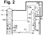
- Figure 2 shows a slight deviation from Figure 1A , nearly all reference being the same as in Figure 1A .
- the deviation concerns the medium-pressure column 104 only, where top condenser and bottom reboiler are forced-flow evaporators respectively. Outside the medium-pressure column 104, the only difference is that the return stream 236 from the top condenser 105 into the low-pressure column 102 is a single two-phase stream instead of separate gas and liquid streams.
- turbine 21 does not expand into the high-pressure column, but the work-expanded air 322 is introduced into the low-pressure column at intermediate height, preferably one section above the single tray 135. Additionally, the splitting of the total feed air 7 is different from Figure 1A . In particular, the turbine air 20 is further compressed just in the turbine-booster 17, resulting in a particular lower inlet pressure level at turbine 21.
- the reference numbers are taken from Figure 1A , the variation can also be applied to Figures 1B and 2 .
Landscapes
- Engineering & Computer Science (AREA)
- Physics & Mathematics (AREA)
- Mechanical Engineering (AREA)
- Thermal Sciences (AREA)
- General Engineering & Computer Science (AREA)
- Health & Medical Sciences (AREA)
- Emergency Medicine (AREA)
- Separation By Low-Temperature Treatments (AREA)
Abstract
The invention concerns a process for cryogenic air separation and an air separation plant. Such plant comprises three columns for nitrogen-oxygen separation including a high-pressure column (101), a medium-pressure column (104) and a low-pressure column (102) and additionally a crude argon column (107). A first oxygen-enriched fraction (33, 34) from the high-pressure column (101) is sent. being sent to the medium-pressure column (104). A portion (41) of an argon-enriched fraction, which otherwise feeds the crude argon column, is introduced as heating medium into a bottom evaporator (106) of the medium-pressure column (104). A top condenser (105) of the medium-pressure column (104) liquefies nitrogen top gas (50) of the medium-pressure column (104). A liquid impure nitrogen fraction (27) from the medium-pressure column (104). is introduced into the low-pressure column (102), in particular at its top. Another portion (51) of the nitrogen top gas (50) of the medium-pressure column (104) is withdrawn in gaseous form as a product (MPGAN). No part of the liquid nitrogen fraction (54) produced in the top condenser (105) of the medium-pressure column (104) is introduced into the low-pressure column (102).
Description
- The invention concerns a process and an apparatus for cryogenic air separation plant according to the introductory parts of the independent patent claims.
- A system of that type is disclosed in
EP 833118 A2 EP 833118 A2 - Although the known process is already efficient, the object of the invention is to further save energy in the operation of the system.
- The above technical problem is solved by the features of the independent patent claims. Actually, the pure nitrogen section, i.e. the uppermost section of the low-pressure column is omitted in the invention. Such an omission of a separation section normally just saves investment costs, but the skilled person would expect that the energy efficiency decreases. In the invention, it turned out, that such omission in this particular case surprisingly effects an overall energy saving of up to 2.5 %. It is assumed that the increase in efficiency of the separation inside the remaining low-pressure column overcompensates losses caused by the omission of the pure nitrogen section.
- In the invention, no pure liquid nitrogen reflux is required to operate the low-pressure column. The respective pure nitrogen produced at the tops of the medium- and high-pressure column can be used for other purposes, e.g. increasing the reflux and thereby improving the separation in those columns, or withdrawing pressurized gaseous nitrogen products, e.g. the medium-pressure gaseous nitrogen product mentioned in the patent claims.
- For cooling the top condenser, a second oxygen-enriched fraction may be withdrawn from the medium-pressure column and introduced into the top condenser of the medium-pressure column as cooling medium, where it is at least partially evaporated to produce an oxygen-enriched gas. Such oxygen enriched gas is preferably introduced into the low pressure column in particular at least one practical separation stage above the argon condenser for better matching of equilibrium composition and/or reduction of mixing losses.
- The advantages of the invention surface especially when the crude argon column is operated as argon rejection column. In particular in such case, the invention may be combined with a known method to integrate the crude argon column and the crude argon condenser into the vessel of the low-pressure column as previously described in
EP 3133361 A1 =US 20170051971 A1 . - The dividing wall in the divided wall section of this embodiment may be a flat sheet. Alternatively it may comprise a cylindrical wall separating the intermediate mass exchange region and the mass exchange region of the crude argon column as the vertical wall. Examples for such type of divided wall columns as shown in
WO 2019040249 A1 . - Both, the top condenser and the bottom evaporator are usually condenser-evaporators (briefly called condensers). In one embodiment of the invention, both condenser-evaporators are bath evaporators; in another embodiment both are forced-flow evaporators. In a third and forth embodiment both evaporator types are mixed.
- In a bath evaporator, liquid circulates by the thermosiphon effect through the evaporation space of a heat exchanger which is arranged in a liquid bath of the liquid to be evaporated. In a forced-flow (or once-through) evaporator, a liquid stream is forced through the evaporation space by means of its own pressure and partly evaporated therein. Said pressure may be generated for example by a liquid column in the supply line to the evaporator space, and thus purely hydrostatically. Here, the height of said liquid column corresponds to the pressure loss in the evaporation space. The gas-liquid mixture emerging from the evaporation space is sent to a downstream process step or to a downstream device, and in particular is not introduced into a liquid bath of the condenser-evaporator, from which bath the fraction remaining in liquid form would be drawn in again.
- In the drawings, two embodiments of the invention are shown and further details of the invention are explained.
-
Figure 1A shows a plant with a distillation column system comprising a high-pressure column 101, a low-pressure column and amain condenser 103 being a bath evaporator, those three being connected in the manner of a classical Linde double column. The distillation system for nitrogen-oxygen separation further comprises a medium-pressure column 104 having atop condenser 105 and abottom reboiler 106, both being bath evaporator in this embodiment. There is also an oxygen-argon separation in form of acrude argon column 107 integrated into the low-pressure column as a part of a divided wall section having a dividingwall 109 separating two independent distillation sections, anintermediate section 110 of the low-pressure column and theargon column 107. Low-pressure column 102, theargon column 107 and its top condenser 108 (and, as usual, the main condenser 103) are arranged in acommon vessel 111. The construction of the low-pressure column and the integration of the argon column and condenser is explained in detail in the above mentionedEP 3133361 A1 =US 20170051971 A1 . - The
main condenser 103 is formed in the example by a bath evaporator, in particular by three stage cascade evaporator, i.e. a multilevel pocket evaporator. The low-pressure column 102 also has an uppermass transfer region 131 and a lower mass transfer region 132. - In the air separation plant shown of
Figure 1A , atmospheric air (AIR) 1 enters the plant via afilter 2. It is compressed to a pressure slightly above the operating pressure of the high-pressure column 101 in a multi-stage intercooledmain air compressor 3 and precooled anair precooling unit 4. Theprecooled air 5 is purified in a purification unit 6 (typically formed by a pair of molecular sieve adsorbers). A firstpartial stream 8 of the purifiedfeed air 7 is fed to amain heat exchanger 9 and cooled therein down to the cold end. The cooledfeed air 10 is sent vialine 11 in gaseous form to the bottom of the high-pressure column 101. - A second
partial stream 12 of the purifiedfeed air 7 is compressed in a twobooster compressor stages throttle stream 13 after cooling in the main heat exchanger is not valve expanded, but work-expanded to about high-pressure column pressure in a dense fluid turbine 14 (sometimes called liquid turbine). The expandedliquid stream 15 is introduced in liquid form into the high-pressure column 101 at a first intermediate height. - A third
partial stream 16 is withdrawn between the twobooster stages booster 17 with aftercooler 18. The boostered third partial stream is cooled in themain heat exchanger 9 until an intermediate temperature and then withdrawn vialine 20 and work-expanded inturbine 21 in gaseous form. The expanded thirdpartial stream 22 is mixed with the cold firstpartial stream 10 and sent to the high-pressure column as gaseous feed vialine 11. - A
nitrogen gas stream pressure column 101 is introduced into the liquefaction space of themain condenser 103. In the liquefaction space of themain condenser 103,liquid nitrogen 25 is produced and at least a first portion thereof is guided as a firstliquid nitrogen stream 26 to the first high-pressure column 101. - Liquid oxygen is dropping down from the lowermost
mass transfer layer 112 of the low-pressure column 102 into the bath of themain condenser 103. It is introduced into the evaporation space of themain condenser 103. Gaseous oxygen is formed in the evaporation space of themain condenser 103. At least a first portion thereof is introduced into the low-pressure column 102, so that it flows upward into the lowermostmass transfer layer 112 of the low-pressure column 102; a second portion can be obtained directly, if required, as gaseous oxygen product and warmed in the main heat exchanger 308 (not implemented in this embodiment). - A
portion 29 of the reflux liquid for the low-pressure column 102 is formed by a nitrogen-enrichedliquid 27 which is withdrawn from the high-pressure column 101 from a second intermediate height and cooled down in acountercurrent subcooler 28. Impurenitrogen 30 is withdrawn from the top of the low-pressure column 102 and guided as waste gas through thesubcooler 28 and through theconduit 31 to themain heat exchanger 9. Aportion 32 of the warm waste gas may be used as a regeneration gas in thepurification unit 6. - An oxygen-enriched bottoms liquid stream is withdrawn as a first oxygen-enriched
fraction 33 from the high-pressure column 101 and cooled in thesubcooler 28. In the example, the entire cooledbottoms liquid 34 is fed to the bottom or - as shown in the drawing - to an intermediate height of the medium-pressure column 104.Fig. 1B Aportion 63 may be directly introduced into the low-pressure column. The bottom liquid of the medium-pressure column is withdrawn as second oxygen-enrichedfraction 35 and sent as a cooling medium to thetop condenser 105. It is partially evaporated in the evaporation space. The evaporatedportion 36 and the remainingliquid 37 are introduced into the low-pressure column 102 at different heights separated by a separation section being part of theupper region 131. From an intermediate height of the medium-pressure column 104, a liquidimpure nitrogen stream 52 is withdrawn and introduced into the top of the low-pressure column 102. Aportion 53 of thetop nitrogen gas 50 of the medium-pressure column 104 is completely or nearly completely (excluding non-condensable components) liquefied in thetop condenser 105. The completeliquefied fraction 54 is fed back to the top of the medium-pressure column 104 as reflux. No portion is fed to other columns or withdrawn as a final liquid product. In a variant, a portion of such liquid nitrogen from the top of the medium-pressure column maybe withdrawn as a final liquid nitrogen product. In another variant, an additional internal compression stream could be taken from the top of the medium-pressure column and sent to an internal compression pump likepump 57. Additionally or alternatively, final liquid products may be recovered from the top of the medium-pressure column and/or fromlines - The liquid running off from the
upper region 131 of the low-pressure column is collected by aliquid collector 134. In this embodiment, such liquid comes from singlepractical tray 135 being part of theupper region 131. It is introduced vialine 38 into the evaporation space of the argon columntop condenser 108. The argon columntop condenser 108 is a forced-flow evaporator in this embodiment. Theportion 39 partially evaporated in thetop condenser 108 flows back into the uppermass transfer region 131 and theportion 40 remaining in liquid form is fed into the intermediatemass transfer region 110 of the low-pressure column 102. The nearlylowest portion 136 of theupper region 131 between the introduction oflines single sieve tray 135 already mentioned above belowsection 136. If such tray is present, it is then regarded as part of theupper region 131. - The argon-enriched gas exiting the lower
mass transfer region 133 at its top is split.. A first portion of the argon-enriched gas flows into the intermediatemass transfer region 110 like in every low-pressure column and works as rising vapor in the intermediatemass transfer region 110. A second portion of the argon-enriched gas constitutes the "argon-enriched fraction". A first portion of such argon-enriched fraction flows into thecrude argon column 107 and works as rising vapor in the crude argon column. This is similar to each argon plant, but without conduits between low-pressure column and the bottom of the argon column. Asecond portion 41 of the argon-enriched fraction is used as heating medium in thebottom evaporator 106 of the medium-pressure column. The resulting liquid or two-phase stream 42 is sent back to the low-pressure column 102. - The argon-enriched "product" 43 of the argon column is removed in gaseous form from the
argon column 107 or thetop condenser 108 thereof, guided through themain heat exchanger 9 via a separate passage group and withdrawn (ATM) as a waste gas. Alternatively, it would be possible to mix the argon-enrichedfraction 43 with the impure nitrogen and guide the mixture through themain heat exchanger 9. - The liquid air from the
main heat exchanger 9 is fed via theconduit 15 to the high-pressure column 101 at a first intermediate height. At least aportion 45 is withdrawn immediately and introduced via thesubcooler 28 and aconduit 46 into the low-pressure column 102, specifically at least one mass exchange section above thefeed 36 from thetop condenser 105 of the medium-pressure column 104. -
Liquid oxygen main condenser 103. At least aportion 48 is fed to an internal compression. This involves pumping theliquid oxygen 48 by means of apump 49 to a high product pressure, evaporating it or (if its pressure is supercritical) pseudo-evaporating it in themain heat exchanger 9 under this high product pressure, warming it to about ambient temperature and finally recovering it as the gaseous compressed oxygen product GOXIC . Such pressurized oxygen is the main product of the plant of the embodiment. - A further product from the plant is pressurized nitrogen, which is withdrawn directly from the top of the medium-pressure column (
conduits 50, 51), conducted to themain heat exchanger 9, warmed therein and finally obtained as gaseous compressed nitrogen product MPGAN. Pressurized nitrogen is withdrawn as a further product directly in gaseous form from the distillation system, i.e. directly from the top of the medium-pressure column (conduits 23, 55), conducted to themain heat exchanger 9, warmed therein and finally obtained as a further gaseous compressed nitrogen product PGAN. A portion thereof can be used as seal gas (Sealgas). - In addition, a
portion 56 of theliquid nitrogen 25 produced in themain condenser 103 can be fed to an internal compression (pump 57) and obtained as gaseous high-pressure nitrogen product GANIC. The plant can also supply liquid products LOX, LIN. - If the pressure of the MPGAN product is not sufficient for the client's purpose, it may be externally compressed in a
feed compressor 70 withaftercooler 71 and possibly admixed to the PGAN stream. If the pressure of the PGAN product is not sufficient, it can be externally compressed in aproduct compressor 72 withaftercooler 73, either separately or together with the compressed MPGAN stream as shown in the drawing, and finally withdrawn as HPGAN product. - In a specific example, the mass transfer elements in the low-
pressure column 102 are formed exclusively by structured packing (despite single tray 135). The oxygen section (133 and below) of the low-pressure column 102 is equipped with a structured packing having a specific surface area of 750 m2/m3 or alternatively 1200 m2/m3 ; in the other sections, the packing has a specific surface area of 750 or 500 m2/m3. Departing from that, it is possible to combine structured packing of different specific surface area within any of the sections mentioned. Theargon column 152, in the embodiment, contains exclusively packing having a specific surface area of 1200 m2/m3 or alternatively 750 m2/m3. In the high-pressure column 101, the mass transfer elements are formed exclusively by structured packing having a specific surface area of 1200 m2/m3 or 750 m2/m3. Alternatively, at least a portion of the mass transfer elements in the high-pressure column 101 could be formed by conventional distillation trays, for example by sieve trays. -
Figure 1A includes a krypton and xenon recovery.Liquid oxygen 59 containing all the higher-boiling components andliquid oxygen 58 being free of higher-boiling components are fed to a classical Kr-Xe recovery system comprising a Kr-Xe enrichment column (C1) 61 having a bottom reboiler and producing a Kr-Xe concentrate 60 (Crude Kr/Xe). The bottom reboiler is heated by aportion 62 of thegaseous feed air 11. - In an alternative embodiment, there would be no recovery of krypton and xenon. In such case, the
liquid oxygen 48 is directly withdrawn from the bottom of the low-pressure column, like shown forline 59 inFigure 1A . There will be no additional connections immediately above themain condenser 103 contrary to the connections forlines Figure 1A . -
Figure 1B regards an embodiment similar toFigure 1A , but differing in the kind of transfer of thebottom liquid 33 of the high-pressure column 101 to the low-pressure column 102. Whilst inFigure 1A all such liquid is indirectly fed to the low-pressure column, i.e. through the medium-pressure column 104 and itstop condenser 105, inFigure 1B ,portion 63 of such liquid 33, 34 is directly introduced into the low-pressure column 102. The gaseous andliquid portions top condenser 105 are introduced at the same height into the low-pressure column 102 in this embodiment. The nearlylowest portion 136 of theupper region 131 is arranged between the introduction oflines line 63 at the top ofsuch section 136. This section is still relatively short, normally 7 theoretical trays or less. -
Figure 2 shows a slight deviation fromFigure 1A , nearly all reference being the same as inFigure 1A . The deviation concerns the medium-pressure column 104 only, where top condenser and bottom reboiler are forced-flow evaporators respectively. Outside the medium-pressure column 104, the only difference is that thereturn stream 236 from thetop condenser 105 into the low-pressure column 102 is a single two-phase stream instead of separate gas and liquid streams. - In the embodiment of
Figure 3 ,turbine 21 does not expand into the high-pressure column, but the work-expandedair 322 is introduced into the low-pressure column at intermediate height, preferably one section above thesingle tray 135. Additionally, the splitting of thetotal feed air 7 is different fromFigure 1A . In particular, theturbine air 20 is further compressed just in the turbine-booster 17, resulting in a particular lower inlet pressure level atturbine 21. The reference numbers are taken fromFigure 1A , the variation can also be applied toFigures 1B and2 .
Claims (10)
- Process for cryogenic air separation using an air separation plant having a high-pressure column (101) being operated at a first pressure, a medium-pressure column (104) being operated at a second pressure being lower than the first pressure, a low-pressure column (102) being operated at a third pressure being lower than the second pressure and a crude argon column (107),- compressed air (8, 12, 19) being cooled in a main heat exchanger (9),- cooled air (11) from the main heat exchanger (9) being introduced into the high-pressure column (101),- a first oxygen-enriched fraction (33, 34) from the high-pressure column (101) being sent to the medium-pressure column (104),- a first portion of an argon-enriched fraction from the low-pressure column being introduced into the crude argon column (107) as rising vapor,- a second portion (41) of the argon-enriched fraction being introduced as heating medium into a bottom evaporator (106) of the medium-pressure column (104),- a nitrogen top gas (50) being produced in the medium-pressure column,- at least a first portion (53) of the nitrogen top gas (50) being introduced into a top condenser (105) of the medium-pressure column (104) and liquefied there in indirect heat exchange with a cooling medium (35) to produce a liquid nitrogen fraction (54),- a liquid impure nitrogen fraction (27) being withdrawn from an intermediate height of the medium-pressure column (52) and- the liquid impure nitrogen fraction (52) being introduced into the low-pressure column (102),
characterized in that- the liquid impure nitrogen fraction (52) withdrawn from the medium-pressure column (104) is introduced at the top of the low-pressure column (102),- a second portion (51) of the nitrogen top gas (50) of the medium-pressure column (104) is withdrawn in gaseous form, warmed in the main heat exchanger (9) und withdrawn as medium-pressure gaseous nitrogen product (MPGAN) and- no part of the liquid nitrogen fraction (54) produced in the top condenser (105) of the medium-pressure column (104) is introduced into the low-pressure column (102). - Process according to claim 1, whereby a second oxygen-enriched fraction is withdrawn from the medium-pressure column (102) and introduced into the top condenser (105) of the medium-pressure column (102) as cooling medium (35), where it is at least partially evaporated to produce an oxygen-enriched gas (36).
- Process according to claim 2, whereby the oxygen enriched gas (36) is introduced into the low pressure column (102), in particular at least one practical separation stage above the argon condenser (108).
- Process according to any one of the proceedings claims, whereby- the low-pressure column (102), the crude argon column (107) and a condenser-evaporator operated as top condenser (109) of the crude argon column (107) are arranged in a common vessel (111),- the low-pressure column (102) comprises an upper mass exchange region (131), an intermediate mass exchange region (110) and a lower mass exchange region (133),- the top condenser (108) of the crude argon column (107 is arranged below the upper mass exchange region (131) of the low-pressure column,- the intermediate mass exchange region and a mass exchange region of the crude argon column (107) are commonly arranged below the top condenser (108) of the crude argon column in a section of the common vessel (111), which is configured as a divided wall section having a vertical internal wall (109) and- the lower mass exchange section (133) is arranged below the divided wall section.
- Process according to claim 4, whereby the divided wall section comprises a cylindrical wall separating the intermediate mass exchange region (110) and the mass exchange region of the crude argon column (107) as the vertical wall.
- Process according to any one of the proceedings claims, whereby at least one of the top condenser and the bottom evaporator is a bath evaporator.
- Process according to any one of the proceedings claims, whereby at least one of the top condenser and the bottom evaporator is a forced-flow evaporator.
- Process according to any one of the proceedings claims, whereby the process has a single cryogenic expansion turbine being an air turbine (21) for work-expansion of gas.
- Process according to claim 8, whereby the expanded air from the air turbine is introduced (15) either into the high-pressure column (101) or into the low-pressure column (102).
- Air separation plant having a high-pressure column (101) configured to be operated at a first pressure, a medium-pressure column (104) configured to be operated at a second pressure being lower than the first pressure, a low-pressure column (102) configured to be operated at a third pressure being lower than the second pressure and a crude argon column (107),
the plant being further configured for- compressed air (8, 12, 19) being cooled in a main heat exchanger (9),- cooled air (11) from the main heat exchanger being introduced into the high-pressure column (101),- a first oxygen-enriched fraction (33, 34) from the high-pressure column (101) being sent to the medium-pressure column (104),- a first portion of an argon-enriched fraction from the low-pressure column being introduced into the crude argon column (107) as rising vapor,- a second portion (41) of the argon-enriched fraction being introduced as heating medium into a bottom evaporator (106) of the medium-pressure column (104),- a nitrogen top gas (50) being produced in the medium-pressure column,- at least a first portion (53) of the nitrogen top gas (50) being introduced into a top condenser (105) of the medium-pressure column (104) and liquefied there in indirect heat exchange with a cooling medium (35) to produce a liquid nitrogen fraction (54),- a liquid impure nitrogen fraction (27) being withdrawn from an intermediate height of the medium-pressure column (52) and- the liquid impure nitrogen fraction (52) being introduced into the low-pressure column (102),
characterized in that it is further configured for- the liquid impure nitrogen fraction (52) withdrawn from the medium-pressure column (104) being introduced at the top of the low-pressure column (102),- a second portion (51) of the nitrogen top gas (50) of the medium-pressure column (104) being withdrawn in gaseous form, warmed in the main heat exchanger (9) und withdrawn as medium-pressure gaseous nitrogen product (MPGAN) and- no part of the liquid nitrogen fraction (54) produced in the top condenser (105) of the medium-pressure column (104) being introduced into the low-pressure column (102).
Priority Applications (3)
| Application Number | Priority Date | Filing Date | Title |
|---|---|---|---|
| EP23020347.3A EP4495523A1 (en) | 2023-07-17 | 2023-07-17 | Process for cryogenic air separation and air separation plant |
| PCT/EP2024/025176 WO2025016555A1 (en) | 2023-07-17 | 2024-06-05 | Process for cryogenic air separation and air separation plant |
| CN202480046853.0A CN121532612A (en) | 2023-07-17 | 2024-06-05 | Low-temperature air separation method and air separation equipment |
Applications Claiming Priority (1)
| Application Number | Priority Date | Filing Date | Title |
|---|---|---|---|
| EP23020347.3A EP4495523A1 (en) | 2023-07-17 | 2023-07-17 | Process for cryogenic air separation and air separation plant |
Publications (1)
| Publication Number | Publication Date |
|---|---|
| EP4495523A1 true EP4495523A1 (en) | 2025-01-22 |
Family
ID=87377758
Family Applications (1)
| Application Number | Title | Priority Date | Filing Date |
|---|---|---|---|
| EP23020347.3A Withdrawn EP4495523A1 (en) | 2023-07-17 | 2023-07-17 | Process for cryogenic air separation and air separation plant |
Country Status (3)
| Country | Link |
|---|---|
| EP (1) | EP4495523A1 (en) |
| CN (1) | CN121532612A (en) |
| WO (1) | WO2025016555A1 (en) |
Citations (3)
| Publication number | Priority date | Publication date | Assignee | Title |
|---|---|---|---|---|
| EP0833118A2 (en) | 1996-09-20 | 1998-04-01 | The BOC Group plc | Air separation |
| EP3133361A1 (en) | 2015-08-20 | 2017-02-22 | Linde Aktiengesellschaft | Distillation column system and system for the production of oxygen by cryogenic decomposition of air |
| WO2019040249A1 (en) | 2017-08-25 | 2019-02-28 | Praxair Technology, Inc. | Annular divided wall column for an air separation unit |
-
2023
- 2023-07-17 EP EP23020347.3A patent/EP4495523A1/en not_active Withdrawn
-
2024
- 2024-06-05 WO PCT/EP2024/025176 patent/WO2025016555A1/en not_active Ceased
- 2024-06-05 CN CN202480046853.0A patent/CN121532612A/en active Pending
Patent Citations (4)
| Publication number | Priority date | Publication date | Assignee | Title |
|---|---|---|---|---|
| EP0833118A2 (en) | 1996-09-20 | 1998-04-01 | The BOC Group plc | Air separation |
| EP3133361A1 (en) | 2015-08-20 | 2017-02-22 | Linde Aktiengesellschaft | Distillation column system and system for the production of oxygen by cryogenic decomposition of air |
| US20170051971A1 (en) | 2015-08-20 | 2017-02-23 | Dimitri Goloubev | Distillation column system and plant for production of oxygen by cryogenic fractionation of air |
| WO2019040249A1 (en) | 2017-08-25 | 2019-02-28 | Praxair Technology, Inc. | Annular divided wall column for an air separation unit |
Non-Patent Citations (1)
| Title |
|---|
| "INTERMEDIATE PRESSURE COLUMN IN AIR SEPARATION", RESEARCH DISCLOSURE, KENNETH MASON PUBLICATIONS, HAMPSHIRE, UK, GB, no. 425, 1 September 1999 (1999-09-01), XP000889172, ISSN: 0374-4353 * |
Also Published As
| Publication number | Publication date |
|---|---|
| CN121532612A (en) | 2026-02-13 |
| WO2025016555A1 (en) | 2025-01-23 |
| WO2025016555A8 (en) | 2025-02-27 |
Similar Documents
| Publication | Publication Date | Title |
|---|---|---|
| US6530242B2 (en) | Obtaining argon using a three-column system for the fractionation of air and a crude argon column | |
| US8826692B2 (en) | Method and device for low-temperature air separation | |
| US5533339A (en) | Air separation | |
| US12510294B2 (en) | Process for cryogenic fractionation of air, air fractionation plant and integrated system composed of at least two air fractionation plants | |
| US10845118B2 (en) | Distillation column system and plant for production of oxygen by cryogenic fractionation of air | |
| US5887447A (en) | Air separation in a double rectification column | |
| AU684952B2 (en) | Air separation | |
| US5893276A (en) | Air separation | |
| EP1243883A1 (en) | Air separation | |
| US5660059A (en) | Air separation | |
| US6536232B2 (en) | Method for plant and separating air by cryogenic distillation | |
| KR100660243B1 (en) | Process and apparatus for producing pressurized oxygen and krypton/xenon by low-temperature fractionation of air | |
| KR20010049392A (en) | Cryogenic distillation system for air separation | |
| JP2000356465A (en) | Low-temperature distillating system for separating air | |
| US20130047666A1 (en) | Method and device for obtaining pressurized nitrogen and pressurized oxygen by low-temperature separation of air | |
| US5878598A (en) | Air separation | |
| US5689975A (en) | Air separation | |
| AU2019202524B2 (en) | Method for cryogenic separation of air, and air separation plant | |
| EP2447653A1 (en) | Process for cryogenic air separation using a side condenser | |
| US5862680A (en) | Air separation | |
| WO2025016555A1 (en) | Process for cryogenic air separation and air separation plant | |
| US5819556A (en) | Air separation | |
| US6484534B2 (en) | Process and plant for separating air by cryogenic distillation | |
| EP0952416A2 (en) | Cryogenic rectification system with serial liquid air feed | |
| US5852940A (en) | Air separation |
Legal Events
| Date | Code | Title | Description |
|---|---|---|---|
| PUAI | Public reference made under article 153(3) epc to a published international application that has entered the european phase |
Free format text: ORIGINAL CODE: 0009012 |
|
| STAA | Information on the status of an ep patent application or granted ep patent |
Free format text: STATUS: THE APPLICATION HAS BEEN PUBLISHED |
|
| AK | Designated contracting states |
Kind code of ref document: A1 Designated state(s): AL AT BE BG CH CY CZ DE DK EE ES FI FR GB GR HR HU IE IS IT LI LT LU LV MC ME MK MT NL NO PL PT RO RS SE SI SK SM TR |
|
| STAA | Information on the status of an ep patent application or granted ep patent |
Free format text: STATUS: THE APPLICATION IS DEEMED TO BE WITHDRAWN |
|
| 18D | Application deemed to be withdrawn |
Effective date: 20250723 |