EP4495518A1 - A refrigerator appliance - Google Patents
A refrigerator appliance Download PDFInfo
- Publication number
- EP4495518A1 EP4495518A1 EP24189549.9A EP24189549A EP4495518A1 EP 4495518 A1 EP4495518 A1 EP 4495518A1 EP 24189549 A EP24189549 A EP 24189549A EP 4495518 A1 EP4495518 A1 EP 4495518A1
- Authority
- EP
- European Patent Office
- Prior art keywords
- door
- refrigerator appliance
- light source
- projection surface
- handle recess
- Prior art date
- Legal status (The legal status is an assumption and is not a legal conclusion. Google has not performed a legal analysis and makes no representation as to the accuracy of the status listed.)
- Pending
Links
Images



Classifications
-
- F—MECHANICAL ENGINEERING; LIGHTING; HEATING; WEAPONS; BLASTING
- F25—REFRIGERATION OR COOLING; COMBINED HEATING AND REFRIGERATION SYSTEMS; HEAT PUMP SYSTEMS; MANUFACTURE OR STORAGE OF ICE; LIQUEFACTION SOLIDIFICATION OF GASES
- F25D—REFRIGERATORS; COLD ROOMS; ICE-BOXES; COOLING OR FREEZING APPARATUS NOT OTHERWISE PROVIDED FOR
- F25D23/00—General constructional features
- F25D23/02—Doors; Covers
-
- A—HUMAN NECESSITIES
- A47—FURNITURE; DOMESTIC ARTICLES OR APPLIANCES; COFFEE MILLS; SPICE MILLS; SUCTION CLEANERS IN GENERAL
- A47F—SPECIAL FURNITURE, FITTINGS, OR ACCESSORIES FOR SHOPS, STOREHOUSES, BARS, RESTAURANTS OR THE LIKE; PAYING COUNTERS
- A47F3/00—Show cases or show cabinets
- A47F3/001—Devices for lighting, humidifying, heating, ventilation
-
- A—HUMAN NECESSITIES
- A47—FURNITURE; DOMESTIC ARTICLES OR APPLIANCES; COFFEE MILLS; SPICE MILLS; SUCTION CLEANERS IN GENERAL
- A47F—SPECIAL FURNITURE, FITTINGS, OR ACCESSORIES FOR SHOPS, STOREHOUSES, BARS, RESTAURANTS OR THE LIKE; PAYING COUNTERS
- A47F3/00—Show cases or show cabinets
- A47F3/04—Show cases or show cabinets air-conditioned, refrigerated
- A47F3/0404—Cases or cabinets of the closed type
- A47F3/0426—Details
-
- A—HUMAN NECESSITIES
- A47—FURNITURE; DOMESTIC ARTICLES OR APPLIANCES; COFFEE MILLS; SPICE MILLS; SUCTION CLEANERS IN GENERAL
- A47F—SPECIAL FURNITURE, FITTINGS, OR ACCESSORIES FOR SHOPS, STOREHOUSES, BARS, RESTAURANTS OR THE LIKE; PAYING COUNTERS
- A47F3/00—Show cases or show cabinets
- A47F3/04—Show cases or show cabinets air-conditioned, refrigerated
- A47F3/0404—Cases or cabinets of the closed type
- A47F3/0426—Details
- A47F3/043—Doors, covers
-
- A—HUMAN NECESSITIES
- A47—FURNITURE; DOMESTIC ARTICLES OR APPLIANCES; COFFEE MILLS; SPICE MILLS; SUCTION CLEANERS IN GENERAL
- A47F—SPECIAL FURNITURE, FITTINGS, OR ACCESSORIES FOR SHOPS, STOREHOUSES, BARS, RESTAURANTS OR THE LIKE; PAYING COUNTERS
- A47F3/00—Show cases or show cabinets
- A47F3/04—Show cases or show cabinets air-conditioned, refrigerated
- A47F3/0404—Cases or cabinets of the closed type
- A47F3/0426—Details
- A47F3/0434—Glass or transparent panels
-
- F—MECHANICAL ENGINEERING; LIGHTING; HEATING; WEAPONS; BLASTING
- F25—REFRIGERATION OR COOLING; COMBINED HEATING AND REFRIGERATION SYSTEMS; HEAT PUMP SYSTEMS; MANUFACTURE OR STORAGE OF ICE; LIQUEFACTION SOLIDIFICATION OF GASES
- F25D—REFRIGERATORS; COLD ROOMS; ICE-BOXES; COOLING OR FREEZING APPARATUS NOT OTHERWISE PROVIDED FOR
- F25D23/00—General constructional features
- F25D23/02—Doors; Covers
- F25D23/028—Details
-
- F—MECHANICAL ENGINEERING; LIGHTING; HEATING; WEAPONS; BLASTING
- F25—REFRIGERATION OR COOLING; COMBINED HEATING AND REFRIGERATION SYSTEMS; HEAT PUMP SYSTEMS; MANUFACTURE OR STORAGE OF ICE; LIQUEFACTION SOLIDIFICATION OF GASES
- F25D—REFRIGERATORS; COLD ROOMS; ICE-BOXES; COOLING OR FREEZING APPARATUS NOT OTHERWISE PROVIDED FOR
- F25D27/00—Lighting arrangements
-
- F—MECHANICAL ENGINEERING; LIGHTING; HEATING; WEAPONS; BLASTING
- F25—REFRIGERATION OR COOLING; COMBINED HEATING AND REFRIGERATION SYSTEMS; HEAT PUMP SYSTEMS; MANUFACTURE OR STORAGE OF ICE; LIQUEFACTION SOLIDIFICATION OF GASES
- F25D—REFRIGERATORS; COLD ROOMS; ICE-BOXES; COOLING OR FREEZING APPARATUS NOT OTHERWISE PROVIDED FOR
- F25D2323/00—General constructional features not provided for in other groups of this subclass
- F25D2323/02—Details of doors or covers not otherwise covered
-
- F—MECHANICAL ENGINEERING; LIGHTING; HEATING; WEAPONS; BLASTING
- F25—REFRIGERATION OR COOLING; COMBINED HEATING AND REFRIGERATION SYSTEMS; HEAT PUMP SYSTEMS; MANUFACTURE OR STORAGE OF ICE; LIQUEFACTION SOLIDIFICATION OF GASES
- F25D—REFRIGERATORS; COLD ROOMS; ICE-BOXES; COOLING OR FREEZING APPARATUS NOT OTHERWISE PROVIDED FOR
- F25D2327/00—Lighting arrangements not provided for in other groups of this subclass
- F25D2327/001—Lighting arrangements on the external side of the refrigerator, freezer or cooling box
-
- F—MECHANICAL ENGINEERING; LIGHTING; HEATING; WEAPONS; BLASTING
- F25—REFRIGERATION OR COOLING; COMBINED HEATING AND REFRIGERATION SYSTEMS; HEAT PUMP SYSTEMS; MANUFACTURE OR STORAGE OF ICE; LIQUEFACTION SOLIDIFICATION OF GASES
- F25D—REFRIGERATORS; COLD ROOMS; ICE-BOXES; COOLING OR FREEZING APPARATUS NOT OTHERWISE PROVIDED FOR
- F25D2400/00—General features of, or devices for refrigerators, cold rooms, ice-boxes, or for cooling or freezing apparatus not covered by any other subclass
- F25D2400/36—Visual displays
Definitions
- the invention relates generally to a refrigerator appliance, for example a back bar refrigerator appliance such as the type used in bars and restaurants to refrigerate and display containers such as beverage bottles.
- a refrigerator appliance for example a back bar refrigerator appliance such as the type used in bars and restaurants to refrigerate and display containers such as beverage bottles.
- Known back bar refrigerators used for storing cans and beverages at a predetermined temperature comprise a door having a transparent window and a source of light located inside the refrigerator to help the consumer visualise the contents of the refrigerator. As the source of light is always on, this leads to undesired energy consumption.
- the transparent window in the door typically does not have good thermal insulation properties.
- Some back bar refrigerator appliances have solid doors, which have better thermal insulation properties.
- a solid door does not provide visual access to the contents, which is useful for practical reasons (to visually assess stock), and for marketing reasons (so customers can see what is on offer).
- refrigerator appliance comprising a cuboid frame, a cabinet, and a door
- the door comprises a projection surface that is angled inwardly with respect to a side of the cuboid frame
- the refrigerator further comprises a light source arranged to project light onto the projection surface
- having a light source projecting the light onto the projection surface can illuminate a particular area of the door, for example a handle recess, and/or provide visual information.
- the door is solid.
- a solid door provides good thermal insulation, and the light source may be used to project visual information onto the door, such as information on the contents of the refrigerator appliance.
- the door comprises a transparent window, for example, a glass window.
- the light source may illuminate the contents of the appliance through the transparent window so that any heat generated by the light source is dissipated outside of the cabinet.
- the door comprises a handle recess, and wherein the light source is disposed in the handle recess.
- the light source may therefore illuminate the handle recess, providing a visual indication of the location of the handle recess.
- the handle recess comprises the projection surface.
- the light source is configured to project visual information onto the projection surface.
- the visual information may comprise the type of the contents and/or the quantity of the contents in the refrigerator appliance. Additionally or alternatively, the visual information may comprise a brand name or logo associated with the contents of the refrigerator appliance or the establishment where the refrigerator appliance is located (e.g., a bar or restaurant name). Additionally or alternatively, the visual information may comprise operating parameters of the refrigerator appliance (e.g., a temperature setting or energy use of the refrigerator appliance).
- the handle recess is formed at or near a top of the door and faces downwardly.
- the door comprises a planar door panel, and wherein the projection surface is formed on the planar door panel.
- the door panel may be angled inwardly with respect to the cuboid frame and light and/or visual information can be projected onto the door panel.
- the handle recess extends vertically along one side of the door.
- the handle recess extends vertically along substantially the entire side of the door.
- the light source extends along substantially the entire handle recess.
- the light source is configured to project a light gradient across the projection surface.
- the door comprises a handle member attached to a side of the door and defining a handle recess, wherein the handle member comprises an opening disposed adjacent to a door post of the frame when the door is closed, and wherein the light source is disposed on the door post and directs light through the opening.
- Light from the light source may therefore visually indicate the location of the handle recess, and additionally or alternatively the light source may project visual information on the door panel.
- the light source when the door is open the light source is positioned to illuminate the cabinet.
- the light source when the door is open it can be directed to illuminate the contents of the cabinet when the door is open. This may reduce or eliminate the need for a light source within the cabinet.
- the refrigerator appliance further comprises a seal arranged between the door and the door post, and wherein the light source is disposed outwardly of the seal when the door is closed.
- this may reduce energy use of the refrigerator appliance because heat generated by the light source is dissipated outside of the cabinet.
- the seal may be attached to the door or the door post.
- the refrigerator appliance is a back bar refrigerator appliance, for example a bottle cooler.
- the refrigerator appliance may be a commercial appliance such as the type used in bars and restaurants to refrigerate and display containers such as beverage bottles.
- the terms 'connected', 'attached', 'coupled', 'mounted' are intended to include direct connections between two members without any other members interposed therebetween, as well as, indirect connections between members in which one or more other members are interposed therebetween.
- the terminology includes the words specifically mentioned above, derivatives thereof, and words of similar import.
- back bar refrigerator appliances can be interchangeably used with the term “back bar refrigerator” or the term “bottle cooler”.
- Back bar refrigerator appliances are typically sized to fit within a cavity or recess behind a bar, for example under a worksurface and/or between opposing walls.
- the appliance 100 is a back bar refrigerator appliance or a bottle cooler that is sized to fit within a cavity or recess behind a bar, for example under a worksurface and/or between opposing walls.
- the refrigerator appliance 100 comprises a generally cuboidal frame 108 having top, bottom, front, back, left and right faces. Accordingly, the overall shape of the refrigerator appliance 100 is a cuboid.
- the refrigerator appliance 100 comprises a plurality of cabinets 101, 101', 101", in this example three cabinets.
- Each cabinet 101, 101', 101" has a door 102, 102', 102" that is openable to provide access to the contents of the cabinets 101, 101', 101". It will be appreciated than any number of cabinets 101, 101', 101" and doors 102, 102', 102" may be provided.
- the refrigerator appliance 100 further comprises a technical cabinet 110 located adjacent to the one of the cabinets 101, 101', 101", in this case adjacent to the cabinet 101" with the door 102".
- the technical cabinet 110 houses part of the refrigeration system, particularly those parts that generate heat (i.e., the condenser and compressor), and may additionally house the expansion valve.
- One or more evaporators of the refrigeration system are typically positioned within the storage compartments and act to cool the storage compartments.
- At least one of the doors 102, 102', 102" is solid.
- at least one of the doors 102, 102', 102" comprises a transparent window 103, such as a glass widow.
- a transparent window 103 such as a glass widow.
- other transparent materials, such as plastic, are also contemplated.
- the transparent glass window 103 allows to visualise the contents of the cabinet 101, 101', 101".
- two cabinets 102, 102' comprise glass door and one cabinet 102" comprises a solid door.
- Each door 102, 102', 102" comprises a handle recess 105 that extends inwardly.
- the handle recesses 105 extend inwardly of the cuboid frame 108.
- the handle recesses 105 can be used for opening the doors 102, 102', 102".
- a top 107 of each handle recess 105 includes a lip for a person to grip when opening the door 102, 102', 102".
- the handle recesses 105 each include a projection surface 104 that is angled inwardly, as best seen in Figure 2 . That is, the projection surfaces 104 are angled inwardly relative to the cuboid frame 108.
- the handle recess 105 is formed at or near the top of the door 101, 101', 101", however other locations may be suitable, such as along a side of the door 101, 101', 101".
- the handle recess 105 is horizontal (parallel to the top and bottom of the frame 108 of the refrigerator appliance 100) and the projection surface 104 also extends horizontally.
- the handle recess 105 can be, for example, vertical, or positioned at an angle with respect to the side/top of the door.
- the projection surface 104 may include a plate 106 onto which the light is projected.
- the plate 106 may be of a material, colour and/or reflectivity to improve the clarity of the light and/or visual information projected onto the projection surface 104.
- a light source (not illustrated) can be integrated into the top 107 of the handle recess 105, behind the lip, to project light onto the projection surface 104.
- the light source may be, for example, an LED, LED strip or light guide that illuminates the projection surface 104 to improve visibility of the handle recess 105.
- the light source may project visual information onto the projection surface 104, for example a product name or product logo.
- the light source can comprise a projector configured to project visual information onto the projection surface 104 of the handle recess 105, for example a product name or product logo. Projecting visual information onto the projection surface 104 may also help to improve the visibility of the handle recess 105.
- the light source can comprise an electronic display located on the projection surface 104 of the handle recess 105 and configured to display visual information, for example a product name or product logo. Displaying visual information on the projection surface 104 may also help to improve the visibility of the handle recess 105.
- the handle recess 105 may include a light source, for example an LED or light guide, for illuminating the projection surface 104, and a projector or electronic display for providing visual information on the projection surface 104.
- a light source for example an LED or light guide
- a projector or electronic display for providing visual information on the projection surface 104.
- the refrigerator appliance 100 may include a controller configured to control the light source and/or electronic display.
- the controller is configured to control what light and information is projected onto the projection surface 104 or displayed on the electronic display.
- the controller may include a graphical user interface for input of control information by a user.
- the controller may include a connection, for example a wireless connection, to an external device that can be used to control the light source.
- the light source or electronic display is operable to display information on the contents of the refrigerator appliance 100, such as the type of the contents and/or the quantity of the contents.
- the light source or electronic display is additionally or alternatively operable to display a brand name or logo associated with the contents of the refrigerator appliance 100 or the establishment where the refrigerator appliance is located (e.g., a bar or restaurant name).
- the light source or electronic display may additionally or alternatively be operable to display operating parameters of the refrigerator appliance 100 (e.g., a temperature setting or energy use of the refrigerator appliance 100).
- the controller may switch between displaying different types of visual information, or illumination of the projection surface, according to a program or according to user input.
- the projection surface 104 is angled inwardly and is non-parallel to any of the sides of the cuboid frame 108. This provides an ergonomic line of sight for the consumer to identify the position of the handle recess 105 and clearly see any visual information being presented on the projection surface 104.
- Figures 3 to 6 show a further example refrigerator appliance 300.
- the appliance 300 is a back bar refrigerator appliance or a bottle cooler that is sized to fit within a cavity or recess behind a bar, for example under a worksurface and/or between opposing walls.
- the refrigerator appliance 300 is similar to the refrigerator appliance 100, having a cuboid frame 312 with cabinets 301, 301', 301" and doors 302, 302', 302".
- the refrigerator appliance 300 comprises three cabinets 301, 301', 301".
- Each cabinet 301, 301', 301" has a door 302, 302', 302" that is openable to provide access to the contents of the cabinets 301, 301', 301". It will appreciated that any number of cabinets 301 and doors 302 may be provided.
- each of the doors 302, 302', 302" comprises a door panel 313 that is angled inwardly and provides a projection surface 304.
- the door panel 313 defines a majority of the outer surface of each door 302, 302', 302".
- the door panels 313 may be solid or transparent, for example glass.
- the door panels 313 are angled inwardly towards a handle recess 305 formed vertically along one side of the door 302, 302', 302".
- a light source 306, shown in Figure 6 is located within the handle recess 305 or adjacent to the handle recess 305 and projects light across the front surface of the door panel 313. In this way, the front surface of each door panel 313 provides a projection surface 304.
- the light source 306 may be arranged to create a light gradient across the projection surface 304, as shown in Figure 4 . That is, light from the light source 306 most intensely illuminates the projection surface 304 close to the handle recess 305, and the intensity of illumination reduces further from the handle recess 305. This provides a clear visual indication of the location of the handle recess 305.
- the door panel 313 is angled inwardly towards the top of the door 302, 302', 302" substantially across all the height of the door, thus forming a projection surface 304.
- the recess 305 and the light source 306 are also located at or near the topmost edge of the door and are configured to create a light gradient across the projection surface 304. If the door panel 313 is transparent, the contents of the appliance are illuminated from the top down. If the door panel 313 is solid, the handle recess is illuminated and a light gradient is formed in the height direction of the door.
- the projection surface 304 is only formed in the top part of the door 302, 302', 302".
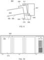
- Figure 8 shows a close up view of the projection surface 304 with the recess 305.
- the light source 306 is configured to be aligned with a gap opening 309 and to illuminate the light onto the projection surface 304 the opening.
- the projection surface 304 can for example cover less than 50% of the surface of the door panel 313. In another example, the projection surface 304 covers less than 25% of the door panel.
- the door panel 313 is solid, i.e. non-transparent, therefore the light is configured to illuminate the handle recess 305, thus allowing the user to more intuitively open the appliance door.
- each door panel 313 is angled inwardly and forms a projection surface 304 that is non-parallel to any of the sides of the refrigerator appliance 300.
- the light source is arranged on the handle, within the handle recess 305.
- Figure 6 shows a further example of how the light source 306 is arranged.
- a handle member 308 is formed on the side of the door 302.
- the handle member 308 is either attached to the door 302 or integrally formed with the door 302.
- the handle member includes a lip 310 for a person to grip when opening the door 302.
- the handle member also includes a gap or opening 309, which may extend partially or entirely along the vertical length of the handle member 308 (e.g., with narrow joining portions extending across the opening 309).
- the opening 309 aligns with the light source 306 provided on the door post 307 when the door 302 is closed.
- the light source 306 and/or the opening 309 are non-parallel to the projection surface 304, creating the light gradient across the projection surface 304.
- the light source 306 and/or the opening 309 may be generally parallel with the front face of the cuboid frame (312, see Figure 3 ).
- the position of the light source 306 on the door post 307 means that when the door 302 is open the light source 306 illuminates the contents of the cabinet 301.
- the light source 306 may be an LED, for example, an LED strip, and/or a light guide with a light source (e.g., an LED) at one or more end.
- a controller can control the illumination of the projection surface 304 by the light source 306 in the same manner as described above.
- the light source 306 may comprise a projector configured to project visual information on the projection surface 304.
- visual information may comprise the type of the contents and/or the quantity of the contents in the refrigerator appliance 300, a brand name or logo associated with the contents of the refrigerator appliance 300 or the establishment where the refrigerator appliance is located (e.g., a bar or restaurant name), and/or operating parameters of the refrigerator appliance 300 (e.g., a temperature setting or energy use of the refrigerator appliance 100).
- the controller may switch between displaying different types of visual information, or illumination of the projection surface 304, according to a program or according to user input.
- the refrigerator appliance 300 in particular the door post 307 comprises a seal 311, as shown in FIG. 6 .
- the seal 311 is configured to contact the handle member 308 when the door is closed.
- the light source 306 is disposed on an outside of the seal 311 when the door 302, 302', 302" is closed, so any heat generated by the light source 306 is dissipated outside of the cabinet 301 and does not increase the energy consumption of the refrigeration system.
- the seal 311 may be provided on the handle member 308 and arranged to contact the door post 307 inwardly of the light source 306 when the door 302 is closed.
Landscapes
- Engineering & Computer Science (AREA)
- Physics & Mathematics (AREA)
- Thermal Sciences (AREA)
- Chemical & Material Sciences (AREA)
- Combustion & Propulsion (AREA)
- Mechanical Engineering (AREA)
- General Engineering & Computer Science (AREA)
- Devices That Are Associated With Refrigeration Equipment (AREA)
- Refrigerator Housings (AREA)
Abstract
The present invention provides a refrigerator appliance (100, 300) comprising a cuboid frame (108, 312), a cabinet (101, 301) and a door (102, 302), wherein the door comprises a projection surface (104, 304) that is angled inwardly with respect to the cuboid frame, and wherein the refrigerator further comprises a light source (306) arranged to project light onto the projection surface.
Description
- The invention relates generally to a refrigerator appliance, for example a back bar refrigerator appliance such as the type used in bars and restaurants to refrigerate and display containers such as beverage bottles.
- Known back bar refrigerators used for storing cans and beverages at a predetermined temperature comprise a door having a transparent window and a source of light located inside the refrigerator to help the consumer visualise the contents of the refrigerator. As the source of light is always on, this leads to undesired energy consumption. In addition, the transparent window in the door typically does not have good thermal insulation properties.
- Some back bar refrigerator appliances have solid doors, which have better thermal insulation properties. However, a solid door does not provide visual access to the contents, which is useful for practical reasons (to visually assess stock), and for marketing reasons (so customers can see what is on offer).
- In accordance with the present invention there is provided a refrigerator appliance according to the appended claims.
- According to an aspect of the present invention, there is provided refrigerator appliance comprising a cuboid frame, a cabinet, and a door, wherein the door comprises a projection surface that is angled inwardly with respect to a side of the cuboid frame, and wherein the refrigerator further comprises a light source arranged to project light onto the projection surface.
- Advantageously, having a light source projecting the light onto the projection surface can illuminate a particular area of the door, for example a handle recess, and/or provide visual information.
- In an embodiment, the door is solid. Advantageously, a solid door provides good thermal insulation, and the light source may be used to project visual information onto the door, such as information on the contents of the refrigerator appliance.
- In an embodiment, the door comprises a transparent window, for example, a glass window. Advantageously, the light source may illuminate the contents of the appliance through the transparent window so that any heat generated by the light source is dissipated outside of the cabinet.
- In an embodiment, the door comprises a handle recess, and wherein the light source is disposed in the handle recess. Advantageously, the light source may therefore illuminate the handle recess, providing a visual indication of the location of the handle recess.
- In an embodiment, the handle recess comprises the projection surface.
- In an embodiment, the light source is configured to project visual information onto the projection surface. In examples, the visual information may comprise the type of the contents and/or the quantity of the contents in the refrigerator appliance. Additionally or alternatively, the visual information may comprise a brand name or logo associated with the contents of the refrigerator appliance or the establishment where the refrigerator appliance is located (e.g., a bar or restaurant name). Additionally or alternatively, the visual information may comprise operating parameters of the refrigerator appliance (e.g., a temperature setting or energy use of the refrigerator appliance).
- In an embodiment, the handle recess is formed at or near a top of the door and faces downwardly.
- In an embodiment, the door comprises a planar door panel, and wherein the projection surface is formed on the planar door panel. In particular, the door panel may be angled inwardly with respect to the cuboid frame and light and/or visual information can be projected onto the door panel.
- In an embodiment, the handle recess extends vertically along one side of the door.
- In an embodiment, the handle recess extends vertically along substantially the entire side of the door.
- In an embodiment, the light source extends along substantially the entire handle recess.
- In an embodiment, the light source is configured to project a light gradient across the projection surface.
- In an embodiment, the door comprises a handle member attached to a side of the door and defining a handle recess, wherein the handle member comprises an opening disposed adjacent to a door post of the frame when the door is closed, and wherein the light source is disposed on the door post and directs light through the opening.
- Light from the light source may therefore visually indicate the location of the handle recess, and additionally or alternatively the light source may project visual information on the door panel.
- In an embodiment, when the door is open the light source is positioned to illuminate the cabinet. In particular, by locating the light source on the door post it can be directed to illuminate the contents of the cabinet when the door is open. This may reduce or eliminate the need for a light source within the cabinet.
- In an embodiment, the refrigerator appliance further comprises a seal arranged between the door and the door post, and wherein the light source is disposed outwardly of the seal when the door is closed.
- Advantageously, this may reduce energy use of the refrigerator appliance because heat generated by the light source is dissipated outside of the cabinet.. In examples, the seal may be attached to the door or the door post.
- In examples, the refrigerator appliance is a back bar refrigerator appliance, for example a bottle cooler. The refrigerator appliance may be a commercial appliance such as the type used in bars and restaurants to refrigerate and display containers such as beverage bottles.
- Embodiments of the invention are now described, by way of example only, hereinafter with reference to the accompanying drawings, in which:
- Figure 1
- illustrates a perspective view of a refrigerator appliance having a handle recess near or at the top of the door;
- Figure 2
- illustrates a close-up view of the handle recess according to the first embodiment of the invention;
- Figure 3
- illustrates a perspective view of the alternative embodiment of a refrigerator appliance having a handle recess on the side of the door;
- Figure 4
- illustrates a front view of the doors of the refrigerator appliance according to the second embodiment of the invention;
- Figure 5
- illustrates a top view of the doors of a refrigerator appliance according to the second embodiment of the invention;
- Figure 6
- illustrates a cross-section of the handle recess of a refrigerator appliance according to the second embodiment of the invention;
- Figures 7A, 7B
- show a front view of alternative embodiments of a refrigeration appliance having a handle recess at or near the top of the door.
- Figure 8
- illustrate a close up view of the recess as shown in
Figure 7B . - Certain terminology is used in the following description for convenience only and is not limiting. The words 'right', `left', 'lower', 'upper', 'front', 'rear', 'upward', 'down' and 'downward' designate directions in the drawings to which reference is made and are with respect to the described component when assembled and mounted. The words 'inner', 'inwardly' and 'outer', 'outwardly' refer to directions toward and away from, respectively, a designated centreline or a geometric centre of an element being described (e.g. central axis), the particular meaning being readily apparent from the context of the description.
- Further, as used herein, the terms 'connected', 'attached', 'coupled', 'mounted' are intended to include direct connections between two members without any other members interposed therebetween, as well as, indirect connections between members in which one or more other members are interposed therebetween. The terminology includes the words specifically mentioned above, derivatives thereof, and words of similar import.
- Further, unless otherwise specified, the use of ordinal adjectives, such as, "first", "second", "third" etc. merely indicate that different instances of like objects are being referred to and are not intended to imply that the objects so described must be in a given sequence, either temporally, spatially, in ranking or in any other manner.
- Like reference numerals are used to depict like features throughout.
- It will be further understood that the term "refrigerator appliance" can be interchangeably used with the term "back bar refrigerator" or the term "bottle cooler". Back bar refrigerator appliances are typically sized to fit within a cavity or recess behind a bar, for example under a worksurface and/or between opposing walls.
- Referring now to
Figure 1 , there is shown arefrigerator appliance 100. In this example, theappliance 100 is a back bar refrigerator appliance or a bottle cooler that is sized to fit within a cavity or recess behind a bar, for example under a worksurface and/or between opposing walls. - The
refrigerator appliance 100 comprises a generallycuboidal frame 108 having top, bottom, front, back, left and right faces. Accordingly, the overall shape of therefrigerator appliance 100 is a cuboid. - Within the
frame 108 therefrigerator appliance 100 comprises a plurality ofcabinets cabinet door cabinets cabinets doors - As shown in
Figure 1 , therefrigerator appliance 100 further comprises atechnical cabinet 110 located adjacent to the one of thecabinets cabinet 101" with thedoor 102". Thetechnical cabinet 110 houses part of the refrigeration system, particularly those parts that generate heat (i.e., the condenser and compressor), and may additionally house the expansion valve. One or more evaporators of the refrigeration system are typically positioned within the storage compartments and act to cool the storage compartments. - In certain embodiments at least one of the
doors doors transparent window 103, such as a glass widow. However other transparent materials, such as plastic, are also contemplated. Thetransparent glass window 103 allows to visualise the contents of thecabinet cabinets 102, 102' comprise glass door and onecabinet 102" comprises a solid door. - Each
door handle recess 105 that extends inwardly. In particular, the handle recesses 105 extend inwardly of thecuboid frame 108. The handle recesses 105 can be used for opening thedoors handle recess 105 includes a lip for a person to grip when opening thedoor projection surface 104 that is angled inwardly, as best seen inFigure 2 . That is, the projection surfaces 104 are angled inwardly relative to thecuboid frame 108. - In an exemplary embodiment, the
handle recess 105 is formed at or near the top of thedoor door Figures 1 and2 thehandle recess 105 is horizontal (parallel to the top and bottom of theframe 108 of the refrigerator appliance 100) and theprojection surface 104 also extends horizontally. However, it is appreciated that other variants are also possible, and thehandle recess 105 can be, for example, vertical, or positioned at an angle with respect to the side/top of the door. - As described below, light can be projected onto the
projection surface 104 to provide illumination of thehandle recess 105 and/or to provide visual information. Theprojection surface 104 may include aplate 106 onto which the light is projected. Theplate 106 may be of a material, colour and/or reflectivity to improve the clarity of the light and/or visual information projected onto theprojection surface 104. - A light source (not illustrated) can be integrated into the top 107 of the
handle recess 105, behind the lip, to project light onto theprojection surface 104. The light source may be, for example, an LED, LED strip or light guide that illuminates theprojection surface 104 to improve visibility of thehandle recess 105. In other examples, the light source may project visual information onto theprojection surface 104, for example a product name or product logo. - In an alternative embodiment, the light source can comprise a projector configured to project visual information onto the
projection surface 104 of thehandle recess 105, for example a product name or product logo. Projecting visual information onto theprojection surface 104 may also help to improve the visibility of thehandle recess 105. - In another alternative embodiment, the light source can comprise an electronic display located on the
projection surface 104 of thehandle recess 105 and configured to display visual information, for example a product name or product logo. Displaying visual information on theprojection surface 104 may also help to improve the visibility of thehandle recess 105. - In a specific embodiment, the
handle recess 105 may include a light source, for example an LED or light guide, for illuminating theprojection surface 104, and a projector or electronic display for providing visual information on theprojection surface 104. - The
refrigerator appliance 100 may include a controller configured to control the light source and/or electronic display. In particular, the controller is configured to control what light and information is projected onto theprojection surface 104 or displayed on the electronic display. The controller may include a graphical user interface for input of control information by a user. Additionally or alternatively, the controller may include a connection, for example a wireless connection, to an external device that can be used to control the light source. - In examples, the light source or electronic display is operable to display information on the contents of the
refrigerator appliance 100, such as the type of the contents and/or the quantity of the contents. In other examples, the light source or electronic display is additionally or alternatively operable to display a brand name or logo associated with the contents of therefrigerator appliance 100 or the establishment where the refrigerator appliance is located (e.g., a bar or restaurant name). In other examples, the light source or electronic display may additionally or alternatively be operable to display operating parameters of the refrigerator appliance 100 (e.g., a temperature setting or energy use of the refrigerator appliance 100). In examples, the controller may switch between displaying different types of visual information, or illumination of the projection surface, according to a program or according to user input. - Advantageously, the
projection surface 104 is angled inwardly and is non-parallel to any of the sides of thecuboid frame 108. This provides an ergonomic line of sight for the consumer to identify the position of thehandle recess 105 and clearly see any visual information being presented on theprojection surface 104. -
Figures 3 to 6 show a furtherexample refrigerator appliance 300. In this example, theappliance 300 is a back bar refrigerator appliance or a bottle cooler that is sized to fit within a cavity or recess behind a bar, for example under a worksurface and/or between opposing walls. - The
refrigerator appliance 300 is similar to therefrigerator appliance 100, having acuboid frame 312 withcabinets doors refrigerator appliance 300 comprises threecabinets cabinet door cabinets cabinets 301 anddoors 302 may be provided. - In this example, each of the
doors door panel 313 that is angled inwardly and provides aprojection surface 304. In examples, thedoor panel 313 defines a majority of the outer surface of eachdoor door panels 313 may be solid or transparent, for example glass. - As shown most clearly in
Figures 4 to 6 , thedoor panels 313 are angled inwardly towards ahandle recess 305 formed vertically along one side of thedoor light source 306, shown inFigure 6 , is located within thehandle recess 305 or adjacent to thehandle recess 305 and projects light across the front surface of thedoor panel 313. In this way, the front surface of eachdoor panel 313 provides aprojection surface 304. - In examples, the
light source 306 may be arranged to create a light gradient across theprojection surface 304, as shown inFigure 4 . That is, light from thelight source 306 most intensely illuminates theprojection surface 304 close to thehandle recess 305, and the intensity of illumination reduces further from thehandle recess 305. This provides a clear visual indication of the location of thehandle recess 305. - In an alternative embodiment, as shown in
Figure 7A , thedoor panel 313 is angled inwardly towards the top of thedoor projection surface 304. In this embodiment, therecess 305 and thelight source 306 are also located at or near the topmost edge of the door and are configured to create a light gradient across theprojection surface 304. If thedoor panel 313 is transparent, the contents of the appliance are illuminated from the top down. If thedoor panel 313 is solid, the handle recess is illuminated and a light gradient is formed in the height direction of the door. - In yet another embodiment, as shown in
Figure 7B , theprojection surface 304 is only formed in the top part of thedoor Figure 8 shows a close up view of theprojection surface 304 with therecess 305. Thelight source 306 is configured to be aligned with agap opening 309 and to illuminate the light onto theprojection surface 304 the opening. Theprojection surface 304 can for example cover less than 50% of the surface of thedoor panel 313. In another example, theprojection surface 304 covers less than 25% of the door panel. In the embodiment shown infigures 7B and 8 , thedoor panel 313 is solid, i.e. non-transparent, therefore the light is configured to illuminate thehandle recess 305, thus allowing the user to more intuitively open the appliance door. - In
Figure 5 the top view of therefrigerator appliance 300 is shown. It can be seen that eachdoor panel 313 is angled inwardly and forms aprojection surface 304 that is non-parallel to any of the sides of therefrigerator appliance 300. - In one example, the light source is arranged on the handle, within the
handle recess 305. -
Figure 6 shows a further example of how thelight source 306 is arranged. As shown, ahandle member 308 is formed on the side of thedoor 302. Thehandle member 308 is either attached to thedoor 302 or integrally formed with thedoor 302. The handle member includes alip 310 for a person to grip when opening thedoor 302. The handle member also includes a gap oropening 309, which may extend partially or entirely along the vertical length of the handle member 308 (e.g., with narrow joining portions extending across the opening 309). As shown inFigure 6 , theopening 309 aligns with thelight source 306 provided on thedoor post 307 when thedoor 302 is closed. - In this way, when the
door 302 is closed light from thelight source 306 is projected across theprojection surface 304 on thedoor panel 313. As illustrated, thelight source 306 and/or theopening 309 are non-parallel to theprojection surface 304, creating the light gradient across theprojection surface 304. In examples, thelight source 306 and/or theopening 309 may be generally parallel with the front face of the cuboid frame (312, seeFigure 3 ). Advantageously, the position of thelight source 306 on thedoor post 307 means that when thedoor 302 is open thelight source 306 illuminates the contents of thecabinet 301. - In examples, the
light source 306 may be an LED, for example, an LED strip, and/or a light guide with a light source (e.g., an LED) at one or more end. A controller can control the illumination of theprojection surface 304 by thelight source 306 in the same manner as described above. - In examples, the
light source 306 may comprise a projector configured to project visual information on theprojection surface 304. For example, visual information may comprise the type of the contents and/or the quantity of the contents in therefrigerator appliance 300, a brand name or logo associated with the contents of therefrigerator appliance 300 or the establishment where the refrigerator appliance is located (e.g., a bar or restaurant name), and/or operating parameters of the refrigerator appliance 300 (e.g., a temperature setting or energy use of the refrigerator appliance 100). In examples, the controller may switch between displaying different types of visual information, or illumination of theprojection surface 304, according to a program or according to user input. - Optionally, the
refrigerator appliance 300, in particular thedoor post 307 comprises aseal 311, as shown inFIG. 6 . Theseal 311 is configured to contact thehandle member 308 when the door is closed. Advantageously, thelight source 306 is disposed on an outside of theseal 311 when thedoor light source 306 is dissipated outside of thecabinet 301 and does not increase the energy consumption of the refrigeration system. In other examples, theseal 311 may be provided on thehandle member 308 and arranged to contact thedoor post 307 inwardly of thelight source 306 when thedoor 302 is closed. - It will be appreciated by persons skilled in the art that the above detailed examples have been described by way of example only and not in any limitative sense, and that various alterations and modifications are possible without departing from the scope of the invention as defined by the appended claims. Various modifications to the detailed examples described above are possible.
- Through the description and claims of this specification, the words "comprise" and "contain" and variations of them mean "including but not limited to", and they are not intended to (and do not) exclude other moieties, additives, components, integers or steps. Throughout the description and claims of this specification, the singular encompasses the plural unless the context otherwise requires. In particular, where the indefinite article is used, the specification is to be understood as contemplating plurality as well as singularity, unless the context requires otherwise.
- Features, integers, characteristics, compounds, chemical moieties or groups described in conjunction with a particular aspect, embodiment or example of the invention are to be understood to be applicable to any other aspect, embodiment or example described herein unless incompatible therewith. All of the features disclosed in this specification (including any accompanying claims, abstract and drawings), and/or all of the steps of any method or process so disclosed, may be combined in any combination, except combinations where at least some of such features and/or steps are mutually exclusive. The invention is not restricted to the details of any foregoing embodiments. The invention extends to any novel one, or any novel combination, of the features disclosed in this specification (including any accompanying claims, abstract or drawings), or to any novel one, or any novel combination, of the steps of any method or process so disclosed.
- It will be appreciated by persons skilled in the art that the above embodiment(s) have been described by way of example only and not in any limitative sense, and that various alterations and modifications are possible without departing from the scope of the invention as defined by the appended claims. Various modifications to the detailed designs as described above are possible.
Claims (15)
- A refrigerator appliance comprising a cuboid frame, a cabinet, and a door, wherein the door comprises a projection surface that is angled inwardly with respect to a side of the cuboid frame, and wherein the refrigerator further comprises a light source arranged to project light onto the projection surface.
- The refrigerator appliance of claim 1, wherein the door is solid.
- The refrigerator appliance of claim 1, wherein the door comprises a transparent window, for example a glass window.
- The refrigerator appliance of any of claims 1 to 3, wherein the door comprises a handle recess, and wherein the light source is disposed in the handle recess.
- The refrigerator appliance of claim 4, wherein the handle recess comprises the projection surface.
- The refrigerator appliance of claim 5, wherein the light source is configured to project visual information onto the projection surface.
- The refrigerator appliance of claim 5 or claim 6, wherein the handle recess is formed at or near a top of the door and faces downwardly.
- The refrigerator appliance of claim 4, wherein the door comprises a planar door panel, and wherein the projection surface is formed on the planar door panel.
- The refrigerator appliance of claim 8, wherein the handle recess extends vertically along one side of the door.
- The refrigerator appliance of claim 9, wherein the handle recess extends vertically along substantially the entire side of the door.
- The refrigerator appliance of claim 10, wherein the light source extends along substantially the entire handle recess.
- The refrigerator appliance of any of claims 8 to 11, wherein the light source is configured to project a light gradient across the projection surface.
- The refrigerator appliance of any of claims 8 to 12, wherein the door comprises a handle member attached to a side of the door and defining the handle recess, wherein the handle member comprises an opening disposed adjacent to a door post of the frame when the door is closed, and wherein the light source is disposed on the door post and directs light through the opening.
- The refrigerator appliance of claim 13, wherein when the door is open the light source is positioned to illuminate the cabinet.
- The refrigerator appliance of claim 13 or claim 14, further comprising a seal arranged between the door and the door post, and wherein the light source is disposed outwardly of the seal when the door is closed.
Applications Claiming Priority (1)
| Application Number | Priority Date | Filing Date | Title |
|---|---|---|---|
| GB2311024.0A GB2632783A (en) | 2023-07-19 | 2023-07-19 | A refrigerator appliance |
Publications (1)
| Publication Number | Publication Date |
|---|---|
| EP4495518A1 true EP4495518A1 (en) | 2025-01-22 |
Family
ID=87758605
Family Applications (1)
| Application Number | Title | Priority Date | Filing Date |
|---|---|---|---|
| EP24189549.9A Pending EP4495518A1 (en) | 2023-07-19 | 2024-07-18 | A refrigerator appliance |
Country Status (3)
| Country | Link |
|---|---|
| US (1) | US20250024964A1 (en) |
| EP (1) | EP4495518A1 (en) |
| GB (1) | GB2632783A (en) |
Families Citing this family (1)
| Publication number | Priority date | Publication date | Assignee | Title |
|---|---|---|---|---|
| EP4494527A1 (en) * | 2023-07-19 | 2025-01-22 | Illinois Tool Works Inc. | A back bar refrigerator appliance |
Citations (5)
| Publication number | Priority date | Publication date | Assignee | Title |
|---|---|---|---|---|
| EP1001235A1 (en) * | 1998-11-09 | 2000-05-17 | Hobby-Wohnwagenwerk Ing. Harald Striewski | Refrigerator for caravan |
| CN101617186B (en) * | 2006-08-31 | 2012-03-14 | 皇家飞利浦电子股份有限公司 | Door for a cold storage device such as a refrigerator or freezer |
| WO2015084792A1 (en) * | 2013-12-05 | 2015-06-11 | The Coca-Cola Company | Systems and methods for a door assembly for a refrigerated merchandizer |
| US20200049401A1 (en) * | 2017-05-01 | 2020-02-13 | Bsh-Hausgeraete Gmbh | Domestic appliance comprising illumination device for recessed grip |
| JP2022088188A (en) * | 2020-12-02 | 2022-06-14 | 三菱電機株式会社 | refrigerator |
Family Cites Families (6)
| Publication number | Priority date | Publication date | Assignee | Title |
|---|---|---|---|---|
| JP2014240730A (en) * | 2013-06-12 | 2014-12-25 | 株式会社東芝 | Refrigerator |
| CN205909600U (en) * | 2016-07-20 | 2017-01-25 | 青岛海高设计制造有限公司 | Refrigerator with do moisture and store up structure |
| CN108119808B (en) * | 2016-11-29 | 2024-04-12 | 博西华电器(江苏)有限公司 | Indicating device for household appliance and household appliance |
| CN110631305A (en) * | 2018-06-23 | 2019-12-31 | 青岛海高设计制造有限公司 | A refrigerator with projection display function |
| CN208567242U (en) * | 2018-06-23 | 2019-03-01 | 青岛海高设计制造有限公司 | A kind of refrigerator with projection display funciton |
| CN111076492A (en) * | 2018-10-22 | 2020-04-28 | 青岛海尔股份有限公司 | Refrigerator with a door |
-
2023
- 2023-07-19 GB GB2311024.0A patent/GB2632783A/en active Pending
-
2024
- 2024-07-18 EP EP24189549.9A patent/EP4495518A1/en active Pending
- 2024-07-19 US US18/777,674 patent/US20250024964A1/en active Pending
Patent Citations (5)
| Publication number | Priority date | Publication date | Assignee | Title |
|---|---|---|---|---|
| EP1001235A1 (en) * | 1998-11-09 | 2000-05-17 | Hobby-Wohnwagenwerk Ing. Harald Striewski | Refrigerator for caravan |
| CN101617186B (en) * | 2006-08-31 | 2012-03-14 | 皇家飞利浦电子股份有限公司 | Door for a cold storage device such as a refrigerator or freezer |
| WO2015084792A1 (en) * | 2013-12-05 | 2015-06-11 | The Coca-Cola Company | Systems and methods for a door assembly for a refrigerated merchandizer |
| US20200049401A1 (en) * | 2017-05-01 | 2020-02-13 | Bsh-Hausgeraete Gmbh | Domestic appliance comprising illumination device for recessed grip |
| JP2022088188A (en) * | 2020-12-02 | 2022-06-14 | 三菱電機株式会社 | refrigerator |
Also Published As
| Publication number | Publication date |
|---|---|
| GB2632783A (en) | 2025-02-26 |
| GB202311024D0 (en) | 2023-08-30 |
| US20250024964A1 (en) | 2025-01-23 |
Similar Documents
| Publication | Publication Date | Title |
|---|---|---|
| EP2725945B1 (en) | Refrigerated merchandise display system | |
| US9212846B2 (en) | Refrigerator | |
| TWI429870B (en) | No internal frame refrigeration refrigerated display cabinet internal lighting equipment | |
| US8070305B2 (en) | Mullion assembly for a refrigerated merchandiser | |
| US6817201B2 (en) | Hot/cold product merchandiser | |
| AU2005329385B2 (en) | Display merchandiser with lighting enhancement | |
| US6484529B2 (en) | Cabinet construction for an ice maker or other refrigeration appliance | |
| CN114502903B (en) | Vacuum insulated cooler | |
| US20250024964A1 (en) | Refrigerator appliance | |
| US20250027712A1 (en) | Refrigerator appliance | |
| US10492629B1 (en) | Refrigerator | |
| US20250027709A1 (en) | Back bar refrigerator appliance | |
| CN213778320U (en) | Vertical refrigerator | |
| JP2001082862A (en) | Refrigerating showcase | |
| GB2631961A (en) | A back bar refrigerator appliance | |
| JP2002081842A (en) | Showcase | |
| JP3889664B2 (en) | Showcase | |
| JP3111475U (en) | Linked showcase | |
| JPH10332255A (en) | Showcase | |
| JP2006296928A (en) | Low temperature showcase | |
| JP5619513B2 (en) | Showcase | |
| HK1118595A (en) | Display merchandiser with lighting enhancement |
Legal Events
| Date | Code | Title | Description |
|---|---|---|---|
| PUAI | Public reference made under article 153(3) epc to a published international application that has entered the european phase |
Free format text: ORIGINAL CODE: 0009012 |
|
| STAA | Information on the status of an ep patent application or granted ep patent |
Free format text: STATUS: THE APPLICATION HAS BEEN PUBLISHED |
|
| AK | Designated contracting states |
Kind code of ref document: A1 Designated state(s): AL AT BE BG CH CY CZ DE DK EE ES FI FR GB GR HR HU IE IS IT LI LT LU LV MC ME MK MT NL NO PL PT RO RS SE SI SK SM TR |
|
| STAA | Information on the status of an ep patent application or granted ep patent |
Free format text: STATUS: REQUEST FOR EXAMINATION WAS MADE |
|
| 17P | Request for examination filed |
Effective date: 20250718 |