EP4495514A1 - Air duct for a refrigerator - Google Patents
Air duct for a refrigerator Download PDFInfo
- Publication number
- EP4495514A1 EP4495514A1 EP24189536.6A EP24189536A EP4495514A1 EP 4495514 A1 EP4495514 A1 EP 4495514A1 EP 24189536 A EP24189536 A EP 24189536A EP 4495514 A1 EP4495514 A1 EP 4495514A1
- Authority
- EP
- European Patent Office
- Prior art keywords
- enclosure
- air
- air duct
- refrigerator
- outlet
- Prior art date
- Legal status (The legal status is an assumption and is not a legal conclusion. Google has not performed a legal analysis and makes no representation as to the accuracy of the status listed.)
- Pending
Links
Images


Classifications
-
- F—MECHANICAL ENGINEERING; LIGHTING; HEATING; WEAPONS; BLASTING
- F25—REFRIGERATION OR COOLING; COMBINED HEATING AND REFRIGERATION SYSTEMS; HEAT PUMP SYSTEMS; MANUFACTURE OR STORAGE OF ICE; LIQUEFACTION SOLIDIFICATION OF GASES
- F25D—REFRIGERATORS; COLD ROOMS; ICE-BOXES; COOLING OR FREEZING APPARATUS NOT OTHERWISE PROVIDED FOR
- F25D17/00—Arrangements for circulating cooling fluids; Arrangements for circulating gas, e.g. air, within refrigerated spaces
- F25D17/04—Arrangements for circulating cooling fluids; Arrangements for circulating gas, e.g. air, within refrigerated spaces for circulating air, e.g. by convection
- F25D17/06—Arrangements for circulating cooling fluids; Arrangements for circulating gas, e.g. air, within refrigerated spaces for circulating air, e.g. by convection by forced circulation
- F25D17/08—Arrangements for circulating cooling fluids; Arrangements for circulating gas, e.g. air, within refrigerated spaces for circulating air, e.g. by convection by forced circulation using ducts
-
- A—HUMAN NECESSITIES
- A47—FURNITURE; DOMESTIC ARTICLES OR APPLIANCES; COFFEE MILLS; SPICE MILLS; SUCTION CLEANERS IN GENERAL
- A47F—SPECIAL FURNITURE, FITTINGS, OR ACCESSORIES FOR SHOPS, STOREHOUSES, BARS, RESTAURANTS OR THE LIKE; PAYING COUNTERS
- A47F3/00—Show cases or show cabinets
- A47F3/04—Show cases or show cabinets air-conditioned, refrigerated
- A47F3/0404—Cases or cabinets of the closed type
- A47F3/0408—Cases or cabinets of the closed type with forced air circulation
-
- F—MECHANICAL ENGINEERING; LIGHTING; HEATING; WEAPONS; BLASTING
- F25—REFRIGERATION OR COOLING; COMBINED HEATING AND REFRIGERATION SYSTEMS; HEAT PUMP SYSTEMS; MANUFACTURE OR STORAGE OF ICE; LIQUEFACTION SOLIDIFICATION OF GASES
- F25D—REFRIGERATORS; COLD ROOMS; ICE-BOXES; COOLING OR FREEZING APPARATUS NOT OTHERWISE PROVIDED FOR
- F25D17/00—Arrangements for circulating cooling fluids; Arrangements for circulating gas, e.g. air, within refrigerated spaces
- F25D17/04—Arrangements for circulating cooling fluids; Arrangements for circulating gas, e.g. air, within refrigerated spaces for circulating air, e.g. by convection
-
- F—MECHANICAL ENGINEERING; LIGHTING; HEATING; WEAPONS; BLASTING
- F25—REFRIGERATION OR COOLING; COMBINED HEATING AND REFRIGERATION SYSTEMS; HEAT PUMP SYSTEMS; MANUFACTURE OR STORAGE OF ICE; LIQUEFACTION SOLIDIFICATION OF GASES
- F25D—REFRIGERATORS; COLD ROOMS; ICE-BOXES; COOLING OR FREEZING APPARATUS NOT OTHERWISE PROVIDED FOR
- F25D17/00—Arrangements for circulating cooling fluids; Arrangements for circulating gas, e.g. air, within refrigerated spaces
- F25D17/04—Arrangements for circulating cooling fluids; Arrangements for circulating gas, e.g. air, within refrigerated spaces for circulating air, e.g. by convection
- F25D17/042—Air treating means within refrigerated spaces
- F25D17/045—Air flow control arrangements
-
- F—MECHANICAL ENGINEERING; LIGHTING; HEATING; WEAPONS; BLASTING
- F25—REFRIGERATION OR COOLING; COMBINED HEATING AND REFRIGERATION SYSTEMS; HEAT PUMP SYSTEMS; MANUFACTURE OR STORAGE OF ICE; LIQUEFACTION SOLIDIFICATION OF GASES
- F25D—REFRIGERATORS; COLD ROOMS; ICE-BOXES; COOLING OR FREEZING APPARATUS NOT OTHERWISE PROVIDED FOR
- F25D17/00—Arrangements for circulating cooling fluids; Arrangements for circulating gas, e.g. air, within refrigerated spaces
- F25D17/04—Arrangements for circulating cooling fluids; Arrangements for circulating gas, e.g. air, within refrigerated spaces for circulating air, e.g. by convection
- F25D17/06—Arrangements for circulating cooling fluids; Arrangements for circulating gas, e.g. air, within refrigerated spaces for circulating air, e.g. by convection by forced circulation
-
- F—MECHANICAL ENGINEERING; LIGHTING; HEATING; WEAPONS; BLASTING
- F25—REFRIGERATION OR COOLING; COMBINED HEATING AND REFRIGERATION SYSTEMS; HEAT PUMP SYSTEMS; MANUFACTURE OR STORAGE OF ICE; LIQUEFACTION SOLIDIFICATION OF GASES
- F25D—REFRIGERATORS; COLD ROOMS; ICE-BOXES; COOLING OR FREEZING APPARATUS NOT OTHERWISE PROVIDED FOR
- F25D2317/00—Details or arrangements for circulating cooling fluids; Details or arrangements for circulating gas, e.g. air, within refrigerated spaces, not provided for in other groups of this subclass
- F25D2317/06—Details or arrangements for circulating cooling fluids; Details or arrangements for circulating gas, e.g. air, within refrigerated spaces, not provided for in other groups of this subclass with forced air circulation
-
- F—MECHANICAL ENGINEERING; LIGHTING; HEATING; WEAPONS; BLASTING
- F25—REFRIGERATION OR COOLING; COMBINED HEATING AND REFRIGERATION SYSTEMS; HEAT PUMP SYSTEMS; MANUFACTURE OR STORAGE OF ICE; LIQUEFACTION SOLIDIFICATION OF GASES
- F25D—REFRIGERATORS; COLD ROOMS; ICE-BOXES; COOLING OR FREEZING APPARATUS NOT OTHERWISE PROVIDED FOR
- F25D2317/00—Details or arrangements for circulating cooling fluids; Details or arrangements for circulating gas, e.g. air, within refrigerated spaces, not provided for in other groups of this subclass
- F25D2317/06—Details or arrangements for circulating cooling fluids; Details or arrangements for circulating gas, e.g. air, within refrigerated spaces, not provided for in other groups of this subclass with forced air circulation
- F25D2317/063—Details or arrangements for circulating cooling fluids; Details or arrangements for circulating gas, e.g. air, within refrigerated spaces, not provided for in other groups of this subclass with forced air circulation with air guides
-
- F—MECHANICAL ENGINEERING; LIGHTING; HEATING; WEAPONS; BLASTING
- F25—REFRIGERATION OR COOLING; COMBINED HEATING AND REFRIGERATION SYSTEMS; HEAT PUMP SYSTEMS; MANUFACTURE OR STORAGE OF ICE; LIQUEFACTION SOLIDIFICATION OF GASES
- F25D—REFRIGERATORS; COLD ROOMS; ICE-BOXES; COOLING OR FREEZING APPARATUS NOT OTHERWISE PROVIDED FOR
- F25D2317/00—Details or arrangements for circulating cooling fluids; Details or arrangements for circulating gas, e.g. air, within refrigerated spaces, not provided for in other groups of this subclass
- F25D2317/06—Details or arrangements for circulating cooling fluids; Details or arrangements for circulating gas, e.g. air, within refrigerated spaces, not provided for in other groups of this subclass with forced air circulation
- F25D2317/066—Details or arrangements for circulating cooling fluids; Details or arrangements for circulating gas, e.g. air, within refrigerated spaces, not provided for in other groups of this subclass with forced air circulation characterised by the air supply
-
- F—MECHANICAL ENGINEERING; LIGHTING; HEATING; WEAPONS; BLASTING
- F25—REFRIGERATION OR COOLING; COMBINED HEATING AND REFRIGERATION SYSTEMS; HEAT PUMP SYSTEMS; MANUFACTURE OR STORAGE OF ICE; LIQUEFACTION SOLIDIFICATION OF GASES
- F25D—REFRIGERATORS; COLD ROOMS; ICE-BOXES; COOLING OR FREEZING APPARATUS NOT OTHERWISE PROVIDED FOR
- F25D2317/00—Details or arrangements for circulating cooling fluids; Details or arrangements for circulating gas, e.g. air, within refrigerated spaces, not provided for in other groups of this subclass
- F25D2317/06—Details or arrangements for circulating cooling fluids; Details or arrangements for circulating gas, e.g. air, within refrigerated spaces, not provided for in other groups of this subclass with forced air circulation
- F25D2317/066—Details or arrangements for circulating cooling fluids; Details or arrangements for circulating gas, e.g. air, within refrigerated spaces, not provided for in other groups of this subclass with forced air circulation characterised by the air supply
- F25D2317/0665—Details or arrangements for circulating cooling fluids; Details or arrangements for circulating gas, e.g. air, within refrigerated spaces, not provided for in other groups of this subclass with forced air circulation characterised by the air supply from the top
-
- F—MECHANICAL ENGINEERING; LIGHTING; HEATING; WEAPONS; BLASTING
- F25—REFRIGERATION OR COOLING; COMBINED HEATING AND REFRIGERATION SYSTEMS; HEAT PUMP SYSTEMS; MANUFACTURE OR STORAGE OF ICE; LIQUEFACTION SOLIDIFICATION OF GASES
- F25D—REFRIGERATORS; COLD ROOMS; ICE-BOXES; COOLING OR FREEZING APPARATUS NOT OTHERWISE PROVIDED FOR
- F25D2317/00—Details or arrangements for circulating cooling fluids; Details or arrangements for circulating gas, e.g. air, within refrigerated spaces, not provided for in other groups of this subclass
- F25D2317/06—Details or arrangements for circulating cooling fluids; Details or arrangements for circulating gas, e.g. air, within refrigerated spaces, not provided for in other groups of this subclass with forced air circulation
- F25D2317/067—Details or arrangements for circulating cooling fluids; Details or arrangements for circulating gas, e.g. air, within refrigerated spaces, not provided for in other groups of this subclass with forced air circulation characterised by air ducts
-
- F—MECHANICAL ENGINEERING; LIGHTING; HEATING; WEAPONS; BLASTING
- F25—REFRIGERATION OR COOLING; COMBINED HEATING AND REFRIGERATION SYSTEMS; HEAT PUMP SYSTEMS; MANUFACTURE OR STORAGE OF ICE; LIQUEFACTION SOLIDIFICATION OF GASES
- F25D—REFRIGERATORS; COLD ROOMS; ICE-BOXES; COOLING OR FREEZING APPARATUS NOT OTHERWISE PROVIDED FOR
- F25D2317/00—Details or arrangements for circulating cooling fluids; Details or arrangements for circulating gas, e.g. air, within refrigerated spaces, not provided for in other groups of this subclass
- F25D2317/06—Details or arrangements for circulating cooling fluids; Details or arrangements for circulating gas, e.g. air, within refrigerated spaces, not provided for in other groups of this subclass with forced air circulation
- F25D2317/067—Details or arrangements for circulating cooling fluids; Details or arrangements for circulating gas, e.g. air, within refrigerated spaces, not provided for in other groups of this subclass with forced air circulation characterised by air ducts
- F25D2317/0672—Outlet ducts
-
- F—MECHANICAL ENGINEERING; LIGHTING; HEATING; WEAPONS; BLASTING
- F25—REFRIGERATION OR COOLING; COMBINED HEATING AND REFRIGERATION SYSTEMS; HEAT PUMP SYSTEMS; MANUFACTURE OR STORAGE OF ICE; LIQUEFACTION SOLIDIFICATION OF GASES
- F25D—REFRIGERATORS; COLD ROOMS; ICE-BOXES; COOLING OR FREEZING APPARATUS NOT OTHERWISE PROVIDED FOR
- F25D2400/00—General features of, or devices for refrigerators, cold rooms, ice-boxes, or for cooling or freezing apparatus not covered by any other subclass
- F25D2400/34—Temperature balancing devices
Definitions
- the invention relates generally to an air duct. More specifically, the invention relates to an air duct for a refrigerator. The invention also relates to a refrigerator including the air duct.
- a refrigerator includes an enclosure that is suitable for keeping the contents stored therein within a prerequisite range of temperatures, and are commonly used to store products such as food and beverages.
- the refrigerator includes an air duct to direct cooling air from a fan of a refrigeration system into the enclosure.
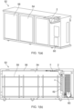
- An example of a known refrigerator 52 with an air duct 2 is shown in Figure 1 .
- the refrigerator 52 has a refrigeration system 60 with a fan that directs cooling air along a passage 62 in a direction denoted by the arrow 'A' towards the air duct 2.
- the air duct 2 directs the cooling air along a direction denoted by the arrow ⁇ B' along the upper surface 56 of the enclosure 54.
- the refrigerator 52 includes shelves 58 that are provided to hold products such as food or beverages.
- the air duct 2 provides a circulation of cooling air inside the enclosure of the refrigerator 52.
- the products that are located at a downstream position of the circulation are cooled less than the products that are located at an upstream position of the cooling air. This results in a large temperature spread of products depending on where the products are located within the refrigerator 52.
- the present invention provides at least an alternative to air ducts and refrigerators of the prior art.
- an air duct for a refrigerator having an enclosure and a refrigeration system with a fan for generating a cooling airflow, the air duct comprising:
- cooling airflow from the refrigeration system is directed by the air outlet into the enclosure in a first direction to cool the enclosure along the first direction, while a portion of the cooling airflow is diverted in a different second direction towards a different part of the enclosure of the refrigerator.
- This improves the distribution of cooling air within the enclosure so that the temperature is more evenly distributed, reducing the temperature spread of products when they are placed within different parts of the enclosure.
- the required average temperature is reached faster to sufficiently cool the products within the enclosure, so that less energy is used to cool the refrigerator.
- the first direction is parallel to an upper surface of the enclosure.
- the air duct and the upper surface of the enclosure define a channel.
- the second direction is parallel to an upper surface of the enclosure.
- the second direction is sideways relative to the first direction.
- the cooling air is spread to more parts of the enclosure, improving the temperature distribution within the enclosure.
- the second direction is downwards relative to the first direction.
- the cooling air is spread to more parts of the enclosure, improving the temperature distribution within the enclosure.
- the second direction is towards the door of the refrigerator.
- the second direction is towards the back of the enclosure.
- the diverter comprises a plurality of openings.
- the diverter comprises one or more louvre vents.
- the louvre vent(s) comprises a plurality of blades. In examples, at least two of the blades point in different directions.
- the air duct further comprises a duct body between the air inlet and the outlet.
- the duct body comprises an inlet body portion adjacent the air inlet.
- the duct comprises an outlet body portion adjacent the air outlet.
- the outlet body portion of the duct body is parallel to the upper surface of the enclosure of the refrigerator.
- the duct body comprises an inlet body portion adjacent the air inlet and an outlet body portion adjacent the air outlet.
- the inlet body portion and the outlet body portion are adjoined by a folded portion.
- an obtuse angle is formed between the inlet body portion and the outlet body portion.
- At least a portion of the duct body is planar.
- the air duct further comprises a fan mounting plate adjacent the air inlet.
- the fan mounting plate comprises at least one opening configured for receiving a fan.
- a refrigerator comprising:
- the refrigerator includes the air duct of the present invention and therefore provides the same advantages as described above.
- the enclosure comprises a first side. In examples, the enclosure comprises a second side opposite the first side. In examples, the enclosure comprises an upper surface. In examples, the enclosure comprises a back surface. In examples, the enclosure comprises at least one door opposite the back surface. In examples, the air duct is arranged on the upper surface of the enclosure. In examples, the refrigerator system is arranged on the first side of the enclosure. In examples, the air outlet is directed towards the second side of the enclosure.
- the diverter of the air duct diverts a portion of the cooling airflow towards the door.
- the door is proximal to the first side.
- the diverter of the air duct diverts a portion of the cooling airflow into the enclosure towards the back surface of the enclosure.
- the refrigerator is a back bar refrigerator appliance.
- a back bar refrigerator appliance is typically sized to fit within a cavity or recess behind a bar, for example under a worksurface and/or between opposing walls.
- the terms 'connected', 'attached', 'coupled', 'mounted' are intended to include direct connections between two members without any other members interposed therebetween, as well as, indirect connections between members in which one or more other members are interposed therebetween.
- the terminology includes the words specifically mentioned above, derivatives thereof, and words of similar import.
- the air duct 102 has an air inlet 104 and an air outlet 106.
- the air outlet 106 is arranged downstream of the air inlet 104 such that a cooling airflow can be directed from the air inlet 104 to the air outlet 106 in use.
- the air duct 102 When applied to a refrigerator, the air duct 102 is positioned in the top of the enclosure and defines a channel (i.e. path) between the wall of the air duct 102 and the upper surface of the refrigerator enclosure.
- the air duct 102 has a diverter 108 arranged between the air inlet 104 and the air outlet 106.
- the diverter 108 is arranged to divert some of the cooling airflow in use, such that instead of moving from the air inlet 104 to the air outlet 106 in a first (i.e. primary) direction, it is instead bypassed and diverted in a second direction away from the air outlet 106 that is different from the first direction.
- the first direction may be across the upper surface of the enclosure.
- the second direction may be towards the front (e.g. door) of the refrigerator.
- the second direction may instead be towards the back of the refrigerator.
- the second direction may be parallel to the upper surface of the enclosure.
- the second direction may instead be non-parallel with the upper surface of the enclosure, for example in a direction downwards relative to the first direction.
- cooling air is supplied by a refrigeration system (160, Figure 8 ) with a fan.
- the details of the refrigeration system 160 may be entirely conventional so will not be described.
- the air duct 102 in this example has a body 120 with two parts.
- the body 120 of the air duct 102 is shown without the diverter 108 in Figure 3 .
- the body 120 of the duct 102 has an inlet body portion 120a adjacent the air inlet 104, and an outlet body portion 120b adjacent the air outlet 106.
- the inlet body portion 120a has a planar surface, angled relative to the air inlet 104.
- the outlet body portion 120b is also planar in this example, and is angled relative to the inlet body portion 120a.
- a fold 122 is provided between the inlet body portion 120a and the outlet body portion 120b, forming an obtuse angle. In this example, the angle between the inlet body portion 120a and the outlet body portion 120b is 120 degrees.
- the sides of the inlet body portion 120a are provided with raised edges 124 that prevent the cooling airflow from escaping the air duct 102 as it moves across the inlet body portion 120a.
- a side of the outlet body portion 120b is provided with a recessed side surface 121.
- a main surface of the diverter 108 is placed onto the outlet body portion 120b, and an engaging surface 112 of the diverter 108 rests against the inlet body portion 120a to hold the diverter 108 in place between the air inlet 104 and the air outlet 106.
- the diverter 108 is provided with an aperture 127 through which a fastener can be inserted to fasten the diverter 108 to the body 120 of the air duct 102.
- the diverter 108 is also provided with another aperture 115 through which another fastener can be inserted to fasten the diverter 108 and air duct 102 to an inner surface of a refrigerator.
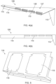
- the diverter 108 has a louvre vent 110 that allows for the passage of air from one side to the other.
- the blades of the louvre vent 110 alternate such that adjacent blades point in different directions (see Figure 4(a) ).
- a distal side of the diverter 108, downstream of the louvre vent 110, is provided with a raised edge 114 that extends upward perpendicular to the outlet body portion 120b.
- the diverter 108 is injection moulded and is formed of polypropylene, but may alternatively be made from sheet metal.
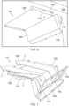
- the air duct 102 is provided with a fan mounting plate 116.
- the fan mounting plate 116 is shown in isolation from the rest of the air duct 102 in Figure 5 .
- the fan mounting plate 116 is provided with two openings 118 into which fans are mounted to draw cooling air through the air inlet 104 from the refrigeration system (160, Figure 8 ). It is envisaged that a different number of openings 118 may be provided in the mounting plate 116, depending on the number of fans to be mounted.
- the fan mounting plate 116 is positioned between the air inlet 104 and the inlet body portion 120a.
- the air duct 102 is attached to the upper surface of the enclosure of the refrigerator by inserting a fastener through the aperture 115.
- the outlet body portion 120b is arranged substantially parallel to the upper surface of the enclosure.
- the diverter 108 is positioned to divert cooling airflow received by the air inlet 104 such that instead of being entirely directed towards the air outlet 106 in a first direction towards the enclosure, a portion of the cooling air is instead diverted away in a second direction towards the enclosure, the second direction being different from the first direction.
- the cooling air is diverted in a second direction towards the recessed side surface (121, Figure 3 ) of the air duct body 120.
- the second direction may be towards another part of the enclosure, so long as it is a different direction to the first direction.
- Cooling air is drawn through the air inlet 104 from the refrigeration system 160, primarily in a first direction towards the air outlet 106 along a flow path denoted by the arrows 'C' and 'D'.
- a portion of the cooling air closer to the diverter 108 i.e. along the flow path direction 'C' is diverted by the diverter 108 towards the louvre vent 110 of the diverter 108, in a downward direction relative to the first direction, along a second direction denoted by the arrow 'E', as seen in Figure 8 .
- the diverter 108 may instead, or in addition, divert the airflow in a direction sideways relative to the first direction.
- the diverter 108 By diverting the airflow in a second direction different from the first direction using the diverter 108, instead of all the cooling airflow being directed downstream towards the air outlet 106, a portion of the cooling airflow is diverted in a different direction. This improves the distribution of cooling airflow, and therefore, temperature, within the enclosure of the refrigerator.
- the blades of the louvre vent 110 are arranged in an alternating manner such that adjacent blades point in different directions, which further distributes the cooling air within the enclosure of the refrigerator. This is because the cooling air diverted by the alternating blades is directed in different directions, and therefore towards different prats of the enclosure.
- the refrigeration system 160 has a fan that supplies cooling air along a passage 162 in a direction denoted by the arrow 'A' towards the air inlet 104 of the air duct 102.
- One or more fans may be provided in the air duct 102 to draw the cooling air into the air duct 102.
- the air duct 102 directs the cooling air along a direction denoted by the arrow ⁇ B' along the upper surface 156 of the enclosure 154. As the cooling air travels along the upper surface 156 of the enclosure 154, it gradually falls into the enclosure to create an air circulation that is concentrated along the upper surface 156 and the lower surface of the enclosure 154.
- the coldness of the air is transferred to the products held within the shelves 158 as it falls to cool those products, such that the air at the lower surface of the enclosure 154 is warmer than the air at the upper surface 156 of the enclosure 154. If a diverter 108 is not provided then the products lower in the enclosure will be cooled to a lesser extent than the products higher in the enclosure. The diverter 108 diverts a portion of the cooling air so that instead of exiting from the air duct 102 from the air outlet 106, the cooling air is diverted by the diverter 108 in a direction denoted by the arrow 'E'.
- the diverter 108 diverts a portion of the cooling air downward towards a lower part of the enclosure 154 away from the upper surface 156 of the refrigerator 152.
- the diverter 108 may divert the cooling air towards the door, which may then reflect the cooling air to a different part of the enclosure 154.
- the diverter 108 may divert the cooling air towards a side of the enclosure away from the air outlet 106, for example to a portion of the enclosure 154 proximal the passage 162.
- the diverter 108 may include a bend to direct the air towards to a part of the enclosure 154 that requires cooling, for example towards the lower surface of the enclosure 154.
- the diverter 108 may divert the cooling air downwards.
Landscapes
- Engineering & Computer Science (AREA)
- Physics & Mathematics (AREA)
- Thermal Sciences (AREA)
- Chemical & Material Sciences (AREA)
- Combustion & Propulsion (AREA)
- Mechanical Engineering (AREA)
- General Engineering & Computer Science (AREA)
- Cold Air Circulating Systems And Constructional Details In Refrigerators (AREA)
Abstract
The present invention provides an air duct (102) for a refrigerator (152) having an enclosure (154) and a refrigeration system (160) with a fan for generating a cooling airflow, the air duct comprising:
an air inlet (104) fluidly couplable to and arranged for receiving the cooling airflow from the refrigeration system;
an air outlet (106) downstream of the air inlet, arranged to direct the cooling airflow from the refrigeration system into the enclosure in a first direction; and
a diverter (108) located between the air inlet and the air outlet configured to divert a portion of the cooling airflow into the enclosure in a second direction different to the first direction.
an air inlet (104) fluidly couplable to and arranged for receiving the cooling airflow from the refrigeration system;
an air outlet (106) downstream of the air inlet, arranged to direct the cooling airflow from the refrigeration system into the enclosure in a first direction; and
a diverter (108) located between the air inlet and the air outlet configured to divert a portion of the cooling airflow into the enclosure in a second direction different to the first direction.
Description
- The invention relates generally to an air duct. More specifically, the invention relates to an air duct for a refrigerator. The invention also relates to a refrigerator including the air duct.
- A refrigerator includes an enclosure that is suitable for keeping the contents stored therein within a prerequisite range of temperatures, and are commonly used to store products such as food and beverages. The refrigerator includes an air duct to direct cooling air from a fan of a refrigeration system into the enclosure. An example of a known
refrigerator 52 with anair duct 2 is shown inFigure 1 . Therefrigerator 52 has arefrigeration system 60 with a fan that directs cooling air along apassage 62 in a direction denoted by the arrow 'A' towards theair duct 2. Theair duct 2 directs the cooling air along a direction denoted by the arrow `B' along theupper surface 56 of theenclosure 54. Therefrigerator 52 includesshelves 58 that are provided to hold products such as food or beverages. - The
air duct 2 provides a circulation of cooling air inside the enclosure of therefrigerator 52. However, the products that are located at a downstream position of the circulation are cooled less than the products that are located at an upstream position of the cooling air. This results in a large temperature spread of products depending on where the products are located within therefrigerator 52. - It would be desirable to provide an air duct for a refrigerator that addresses the above problems.
- The present invention provides at least an alternative to air ducts and refrigerators of the prior art.
- In accordance with the present invention there is provided an air duct and a refrigerator according to the appended claims.
- According to an aspect of the present invention, there is provided an air duct for a refrigerator having an enclosure and a refrigeration system with a fan for generating a cooling airflow, the air duct comprising:
- an air inlet fluidly couplable to and arranged for receiving the cooling airflow from the refrigeration system;
- an air outlet downstream of the air inlet, arranged to direct the cooling airflow from the refrigeration system into the enclosure in a first direction; and
- a diverter located between the air inlet and the air outlet configured to divert a portion of the cooling airflow into the enclosure in a second direction different to the first direction.
- Thus, cooling airflow from the refrigeration system is directed by the air outlet into the enclosure in a first direction to cool the enclosure along the first direction, while a portion of the cooling airflow is diverted in a different second direction towards a different part of the enclosure of the refrigerator. This improves the distribution of cooling air within the enclosure so that the temperature is more evenly distributed, reducing the temperature spread of products when they are placed within different parts of the enclosure. By providing an air duct with a diverter in the claimed manner, the required average temperature is reached faster to sufficiently cool the products within the enclosure, so that less energy is used to cool the refrigerator.
- In examples, the first direction is parallel to an upper surface of the enclosure.
- In examples, the air duct and the upper surface of the enclosure define a channel.
- In examples, the second direction is parallel to an upper surface of the enclosure.
- In examples, the second direction is sideways relative to the first direction. By diverting a portion of the cooling airflow into the enclosure in a second direction that is sideways relative to the first direction, the cooling air is spread to more parts of the enclosure, improving the temperature distribution within the enclosure.
- In examples, the second direction is downwards relative to the first direction. By diverting a portion of the cooling airflow into the enclosure in a second direction that is downwards relative to the first direction, the cooling air is spread to more parts of the enclosure, improving the temperature distribution within the enclosure.
- In examples, the second direction is towards the door of the refrigerator.
- In some examples, the second direction is towards the back of the enclosure.
- In examples, the diverter comprises a plurality of openings.
- In examples, the diverter comprises one or more louvre vents. In examples, the louvre vent(s) comprises a plurality of blades. In examples, at least two of the blades point in different directions.
- In examples, the air duct further comprises a duct body between the air inlet and the outlet. In examples, the duct body comprises an inlet body portion adjacent the air inlet.
- In examples, the duct comprises an outlet body portion adjacent the air outlet. In some examples, the outlet body portion of the duct body is parallel to the upper surface of the enclosure of the refrigerator.
- In examples, the duct body comprises an inlet body portion adjacent the air inlet and an outlet body portion adjacent the air outlet. In examples, the inlet body portion and the outlet body portion are adjoined by a folded portion. In examples, an obtuse angle is formed between the inlet body portion and the outlet body portion.
- In examples, at least a portion of the duct body is planar.
- In examples, the air duct further comprises a fan mounting plate adjacent the air inlet. In examples, the fan mounting plate comprises at least one opening configured for receiving a fan.
- According to another aspect of the present invention, there is provided a refrigerator, comprising:
- an air duct;
- an enclosure: and
- a refrigeration system having a fan for generating a cooling airflow, wherein the refrigeration system is fluidly coupled to and arranged to supply the cooling airflow to the air inlet of the air duct.
- The refrigerator includes the air duct of the present invention and therefore provides the same advantages as described above.
- In examples, the enclosure comprises a first side. In examples, the enclosure comprises a second side opposite the first side. In examples, the enclosure comprises an upper surface. In examples, the enclosure comprises a back surface. In examples, the enclosure comprises at least one door opposite the back surface. In examples, the air duct is arranged on the upper surface of the enclosure. In examples, the refrigerator system is arranged on the first side of the enclosure. In examples, the air outlet is directed towards the second side of the enclosure.
- In examples, the diverter of the air duct diverts a portion of the cooling airflow towards the door. In examples, the door is proximal to the first side.
- In examples, the diverter of the air duct diverts a portion of the cooling airflow into the enclosure towards the back surface of the enclosure.
- In examples, the refrigerator is a back bar refrigerator appliance. A back bar refrigerator appliance is typically sized to fit within a cavity or recess behind a bar, for example under a worksurface and/or between opposing walls.
- Embodiments of the invention are now described, by way of example only, hereinafter with reference to the accompanying drawings, in which:
- Figure 1
- illustrates a known refrigerator with an air duct (a) in a perspective view, and (b) in a schematic view showing the path of cooling air from the refrigeration system, towards the air duct and into the enclosure of the refrigerator;
- Figure 2
- illustrates a perspective view of an air duct including a diverter;
- Figure 3
- illustrates a perspective view of the air duct body;
- Figure 4
- illustrates a diverter (a) in a perspective view, and (b) in a front profile view;
- Figure 5
- illustrates a perspective view of fan mounting plate;
- Figure 6
- illustrates a perspective view of an air duct when in use in the refrigerator;
- Figure 7
- illustrates an air duct showing the flow profile of cooling air; and
- Figure 8
- illustrates a refrigerator with an air duct, showing the path of cooling air from the refrigeration system through the air duct and into the enclosure of the refrigerator.
- Certain terminology is used in the following description for convenience only and is not limiting. The words 'right', 'left', 'lower', 'upper', 'front', 'rear', 'upward', 'down' and 'downward' designate directions in the drawings to which reference is made and are with respect to the described component when assembled and mounted. The words 'inner', 'inwardly' and 'outer', 'outwardly' refer to directions toward and away from, respectively, a designated centreline or a geometric centre of an element being described (e.g. central axis), the particular meaning being readily apparent from the context of the description.
- Further, as used herein, the terms 'connected', 'attached', 'coupled', 'mounted' are intended to include direct connections between two members without any other members interposed therebetween, as well as, indirect connections between members in which one or more other members are interposed therebetween. The terminology includes the words specifically mentioned above, derivatives thereof, and words of similar import.
- Further, unless otherwise specified, the use of ordinal adjectives, such as, "first", "second", "third" etc. merely indicate that different instances of like objects are being referred to and are not intended to imply that the objects so described must be in a given sequence, either temporally, spatially, in ranking or in any other manner.
- Like reference numerals are used to depict like features throughout.
- Referring now to
Figure 2 , there is shown anair duct 102. Theair duct 102 has anair inlet 104 and anair outlet 106. Theair outlet 106 is arranged downstream of theair inlet 104 such that a cooling airflow can be directed from theair inlet 104 to theair outlet 106 in use. When applied to a refrigerator, theair duct 102 is positioned in the top of the enclosure and defines a channel (i.e. path) between the wall of theair duct 102 and the upper surface of the refrigerator enclosure. Theair duct 102 has adiverter 108 arranged between theair inlet 104 and theair outlet 106. Thediverter 108 is arranged to divert some of the cooling airflow in use, such that instead of moving from theair inlet 104 to theair outlet 106 in a first (i.e. primary) direction, it is instead bypassed and diverted in a second direction away from theair outlet 106 that is different from the first direction. The first direction may be across the upper surface of the enclosure. The second direction may be towards the front (e.g. door) of the refrigerator. The second direction may instead be towards the back of the refrigerator. The second direction may be parallel to the upper surface of the enclosure. The second direction may instead be non-parallel with the upper surface of the enclosure, for example in a direction downwards relative to the first direction. By diverting the cooling air in a second direction that is different from the first direction, different circulation routes of cooling air are created to more evenly distribute the cooling air within the enclosure of the refrigerator. In this example, the cooling air is supplied by a refrigeration system (160,Figure 8 ) with a fan. The details of therefrigeration system 160 may be entirely conventional so will not be described. - The
air duct 102 in this example has abody 120 with two parts. Thebody 120 of theair duct 102 is shown without thediverter 108 inFigure 3 . Thebody 120 of theduct 102 has aninlet body portion 120a adjacent theair inlet 104, and anoutlet body portion 120b adjacent theair outlet 106. Theinlet body portion 120a has a planar surface, angled relative to theair inlet 104. Theoutlet body portion 120b is also planar in this example, and is angled relative to theinlet body portion 120a. Afold 122 is provided between theinlet body portion 120a and theoutlet body portion 120b, forming an obtuse angle. In this example, the angle between theinlet body portion 120a and theoutlet body portion 120b is 120 degrees. Other angles are also envisaged, such as 105 degrees or 135 degrees, for example. The sides of theinlet body portion 120a are provided with raisededges 124 that prevent the cooling airflow from escaping theair duct 102 as it moves across theinlet body portion 120a. A side of theoutlet body portion 120b is provided with a recessedside surface 121. - In this example, a main surface of the
diverter 108 is placed onto theoutlet body portion 120b, and anengaging surface 112 of thediverter 108 rests against theinlet body portion 120a to hold thediverter 108 in place between theair inlet 104 and theair outlet 106. Thediverter 108 is provided with anaperture 127 through which a fastener can be inserted to fasten thediverter 108 to thebody 120 of theair duct 102. Thediverter 108 is also provided with anotheraperture 115 through which another fastener can be inserted to fasten thediverter 108 andair duct 102 to an inner surface of a refrigerator. Thediverter 108 has alouvre vent 110 that allows for the passage of air from one side to the other. The blades of thelouvre vent 110 alternate such that adjacent blades point in different directions (seeFigure 4(a) ). A distal side of thediverter 108, downstream of thelouvre vent 110, is provided with a raisededge 114 that extends upward perpendicular to theoutlet body portion 120b. In this example, thediverter 108 is injection moulded and is formed of polypropylene, but may alternatively be made from sheet metal. - In this example, the
air duct 102 is provided with afan mounting plate 116. Thefan mounting plate 116 is shown in isolation from the rest of theair duct 102 inFigure 5 . In this example, thefan mounting plate 116 is provided with twoopenings 118 into which fans are mounted to draw cooling air through theair inlet 104 from the refrigeration system (160,Figure 8 ). It is envisaged that a different number ofopenings 118 may be provided in the mountingplate 116, depending on the number of fans to be mounted. As seen inFigure 2 , thefan mounting plate 116 is positioned between theair inlet 104 and theinlet body portion 120a. - The function of the
air duct 102 will now be described with reference toFigures 6, 7 and8 . - Referring to the example shown in
Figure 6 , theair duct 102 is attached to the upper surface of the enclosure of the refrigerator by inserting a fastener through theaperture 115. Theoutlet body portion 120b is arranged substantially parallel to the upper surface of the enclosure. Thediverter 108 is positioned to divert cooling airflow received by theair inlet 104 such that instead of being entirely directed towards theair outlet 106 in a first direction towards the enclosure, a portion of the cooling air is instead diverted away in a second direction towards the enclosure, the second direction being different from the first direction. In this example, the cooling air is diverted in a second direction towards the recessed side surface (121,Figure 3 ) of theair duct body 120. The second direction may be towards another part of the enclosure, so long as it is a different direction to the first direction. - The air flow path of the cooling air is shown in
Figure 7 . Cooling air is drawn through theair inlet 104 from therefrigeration system 160, primarily in a first direction towards theair outlet 106 along a flow path denoted by the arrows 'C' and 'D'. A portion of the cooling air closer to the diverter 108 (i.e. along the flow path direction 'C') is diverted by thediverter 108 towards thelouvre vent 110 of thediverter 108, in a downward direction relative to the first direction, along a second direction denoted by the arrow 'E', as seen inFigure 8 . It is envisaged that thediverter 108 may instead, or in addition, divert the airflow in a direction sideways relative to the first direction. By diverting the airflow in a second direction different from the first direction using thediverter 108, instead of all the cooling airflow being directed downstream towards theair outlet 106, a portion of the cooling airflow is diverted in a different direction. This improves the distribution of cooling airflow, and therefore, temperature, within the enclosure of the refrigerator. In this example, the blades of thelouvre vent 110 are arranged in an alternating manner such that adjacent blades point in different directions, which further distributes the cooling air within the enclosure of the refrigerator. This is because the cooling air diverted by the alternating blades is directed in different directions, and therefore towards different prats of the enclosure. - As shown in
Figure 8 , therefrigeration system 160 has a fan that supplies cooling air along apassage 162 in a direction denoted by the arrow 'A' towards theair inlet 104 of theair duct 102. One or more fans may be provided in theair duct 102 to draw the cooling air into theair duct 102. Theair duct 102 directs the cooling air along a direction denoted by the arrow `B' along theupper surface 156 of theenclosure 154. As the cooling air travels along theupper surface 156 of theenclosure 154, it gradually falls into the enclosure to create an air circulation that is concentrated along theupper surface 156 and the lower surface of theenclosure 154. The coldness of the air is transferred to the products held within theshelves 158 as it falls to cool those products, such that the air at the lower surface of theenclosure 154 is warmer than the air at theupper surface 156 of theenclosure 154. If adiverter 108 is not provided then the products lower in the enclosure will be cooled to a lesser extent than the products higher in the enclosure. Thediverter 108 diverts a portion of the cooling air so that instead of exiting from theair duct 102 from theair outlet 106, the cooling air is diverted by thediverter 108 in a direction denoted by the arrow 'E'. In this example, thediverter 108 diverts a portion of the cooling air downward towards a lower part of theenclosure 154 away from theupper surface 156 of therefrigerator 152. Thediverter 108 may divert the cooling air towards the door, which may then reflect the cooling air to a different part of theenclosure 154. Thediverter 108 may divert the cooling air towards a side of the enclosure away from theair outlet 106, for example to a portion of theenclosure 154 proximal thepassage 162. Thediverter 108 may include a bend to direct the air towards to a part of theenclosure 154 that requires cooling, for example towards the lower surface of theenclosure 154. Thediverter 108 may divert the cooling air downwards. By diverting the cooling air in a second direction which is different from the first direction, multiple air circulation pathways are created to improve the circulation of cooling air to different parts of theenclosure 154, to allow for even temperature distribution within therefrigerator 152. - It will be appreciated by persons skilled in the art that the above detailed examples have been described by way of example only and not in any limitative sense, and that various alterations and modifications are possible without departing from the scope of the invention as defined by the appended claims. Various modifications to the detailed examples described above are possible.
- Through the description and claims of this specification, the words "comprise" and "contain" and variations of them mean "including but not limited to", and they are not intended to (and do not) exclude other moieties, additives, components, integers or steps. Throughout the description and claims of this specification, the singular encompasses the plural unless the context otherwise requires. In particular, where the indefinite article is used, the specification is to be understood as contemplating plurality as well as singularity, unless the context requires otherwise.
- Features, integers, characteristics, compounds, chemical moieties or groups described in conjunction with a particular aspect, embodiment or example of the invention are to be understood to be applicable to any other aspect, embodiment or example described herein unless incompatible therewith. All of the features disclosed in this specification (including any accompanying claims, abstract and drawings), and/or all of the steps of any method or process so disclosed, may be combined in any combination, except combinations where at least some of such features and/or steps are mutually exclusive. The invention is not restricted to the details of any foregoing embodiments. The invention extends to any novel one, or any novel combination, of the features disclosed in this specification (including any accompanying claims, abstract or drawings), or to any novel one, or any novel combination, of the steps of any method or process so disclosed.
- It will be appreciated by persons skilled in the art that the above embodiment(s) have been described by way of example only and not in any limitative sense, and that various alterations and modifications are possible without departing from the scope of the invention as defined by the appended claims. Various modifications to the detailed designs as described above are possible.
- Aspects of the disclosure are set out in the following numbered clauses:
- Clause 1. An air duct for a refrigerator having an enclosure and a refrigeration system with a fan for generating a cooling airflow, the air duct comprising:
- an air inlet fluidly couplable to and arranged for receiving the cooling airflow from the refrigeration system;
- an air outlet downstream of the air inlet, arranged to direct the cooling airflow from the refrigeration system into the enclosure in a first direction; and
- a diverter located between the air inlet and the air outlet configured to divert a portion of the cooling airflow into the enclosure in a second direction different to the first direction.
-
Clause 2. An air duct according to clause 1, wherein the first direction is parallel to an upper surface of the enclosure. - Clause 3. An air duct according to clause 1 or
clause 2, wherein the air duct and the upper surface of the enclosure define a channel. - Clause 4. An air duct according to any one of the preceding clauses wherein the second direction is parallel to an upper surface of the enclosure.
- Clause 5. An air duct according to any one of the preceding clauses, wherein the second direction is sideways relative to the first direction.
- Clause 6. An air duct according to any one of clauses 1 to 3, wherein the second direction is downwards relative to the first direction.
- Clause 7. An air duct according to any one of the preceding clauses, wherein the diverter comprises a plurality of openings.
- Clause 8. An air duct according to any one of the preceding clauses, wherein the diverter comprises a louvre vent.
- Clause 9. An air duct according to clause 8, wherein the louvre vent comprises a plurality of blades.
- Clause 10. An air duct according to clause 9, wherein at least two of the blades point in different directions.
- Clause 11. An air duct according to any one of the preceding clauses, wherein the second direction is towards a door of the refrigerator or towards a back surface of the enclosure opposite to the door.
- Clause 12. An air duct according to any one of the preceding clauses, further comprising a duct body between the air inlet and the outlet.
- Clause 13. An air duct according to clause 12, wherein the duct body comprises an inlet body portion adjacent the air inlet.
- Clause 14. An air duct according to clause 12 or clause 13, wherein the duct comprises an outlet body portion adjacent the air outlet.
- Clause 15. An air duct according to clause 12, wherein the duct body comprises an inlet body portion adjacent the air inlet and an outlet body portion adjacent the air outlet.
- Clause 16. An air duct according to clause 15, wherein the inlet body portion and the outlet body portion are adjoined by a folded portion.
- Clause 17. An air duct according to clause 16, wherein an obtuse angle is formed between the inlet body portion and the outlet body portion.
- Clause 18. An air duct according to any one of clauses 13 to 17, wherein at least a portion of the duct body is planar.
- Clause 19. An air duct according to any one of the preceding clauses, further comprising a fan mounting plate adjacent the air inlet, comprising at least one opening configured for receiving a fan.
- Clause 20. A refrigerator, comprising:
- an air duct according to any one of clauses 1 to 19;
- an enclosure: and
- a refrigeration system having a fan for generating a cooling airflow, wherein the refrigeration system is fluidly coupled to and arranged to supply the cooling airflow to the air inlet of the air duct.
- Clause 21. A refrigerator according to clause 20, wherein the enclosure comprises a first side, a second side opposite the first side, an upper surface, a back surface and at least one door opposite the back surface.
- Clause 22. A refrigerator according to clause 21, wherein the air duct is arranged on the upper surface of the enclosure, the refrigerator system is arranged on the first side of the enclosure, and the air outlet is directed towards the second side of the enclosure.
- Clause 23. A refrigerator according to clause 22, wherein the diverter of the air duct diverts a portion of the cooling airflow towards the door.
- Clause 24. A refrigerator according to clause 23, wherein the door is proximal to the first side.
- Clause 25. A refrigerator according to clause 22, wherein the diverter of the air duct diverts a portion of the cooling airflow into the enclosure towards the back surface of the enclosure.
Claims (15)
- An air duct for a refrigerator having an enclosure and a refrigeration system with a fan for generating a cooling airflow, the air duct comprising:an air inlet fluidly couplable to and arranged for receiving the cooling airflow from the refrigeration system;an air outlet downstream of the air inlet, arranged to direct the cooling airflow from the refrigeration system into the enclosure in a first direction; anda diverter located between the air inlet and the air outlet configured to divert a portion of the cooling airflow into the enclosure in a second direction different to the first direction.
- An air duct according to claim 1, wherein the first direction is parallel to an upper surface of the enclosure.
- An air duct according to claim 1 or claim 2, wherein the air duct and the upper surface of the enclosure define a channel.
- An air duct according to any one of the preceding claims wherein the second direction is parallel to an upper surface of the enclosure.
- An air duct according to any one of the preceding claims, wherein the second direction is sideways relative to the first direction.
- An air duct according to any one of claims 1 to 3, wherein the second direction is downwards relative to the first direction.
- An air duct according to any one of the preceding claims, wherein the diverter comprises a plurality of openings.
- An air duct according to any one of the preceding claims, wherein the diverter comprises a louvre vent, optionally wherein the louvre vent comprises a plurality of blades, and optionally wherein at least two of the blades point in different directions.
- An air duct according to any one of the preceding claims, wherein the second direction is towards a door of the refrigerator or towards a back surface of the enclosure opposite to the door.
- An air duct according to any one of the preceding claims, further comprising a duct body between the air inlet and the outlet.
- An air duct according to claim 10, wherein the duct body comprises an inlet body portion adjacent the air inlet, and optionally wherein the duct comprises an outlet body portion adjacent the air outlet, and optionally wherein at least a portion of the duct body is planar.
- An air duct according to claim 10, wherein the duct body comprises an inlet body portion adjacent the air inlet and an outlet body portion adjacent the air outlet, and optionally wherein the inlet body portion and the outlet body portion are adjoined by a folded portion, and optionally wherein an obtuse angle is formed between the inlet body portion and the outlet body portion, and optionally wherein at least a portion of the duct body is planar.
- An air duct according to any one of the preceding claims, further comprising a fan mounting plate adjacent the air inlet, comprising at least one opening configured for receiving a fan.
- A refrigerator, comprising:an air duct according to any one of claims 1 to 13;an enclosure: anda refrigeration system having a fan for generating a cooling airflow, wherein the refrigeration system is fluidly coupled to and arranged to supply the cooling airflow to the air inlet of the air duct.
- A refrigerator according to claim 14, wherein the enclosure comprises a first side, a second side opposite the first side, an upper surface, a back surface and at least one door opposite the back surface, andoptionally wherein the air duct is arranged on the upper surface of the enclosure, the refrigerator system is arranged on the first side of the enclosure, and the air outlet is directed towards the second side of the enclosure, andoptionally wherein the diverter of the air duct diverts a portion of the cooling airflow towards the door, andoptionally wherein the door is proximal to the first side, andoptionally wherein the diverter of the air duct diverts a portion of the cooling airflow into the enclosure towards the back surface of the enclosure.
Applications Claiming Priority (1)
| Application Number | Priority Date | Filing Date | Title |
|---|---|---|---|
| GB2311023.2A GB2631960A (en) | 2023-07-19 | 2023-07-19 | Air duct for a refrigerator |
Publications (1)
| Publication Number | Publication Date |
|---|---|
| EP4495514A1 true EP4495514A1 (en) | 2025-01-22 |
Family
ID=87758610
Family Applications (1)
| Application Number | Title | Priority Date | Filing Date |
|---|---|---|---|
| EP24189536.6A Pending EP4495514A1 (en) | 2023-07-19 | 2024-07-18 | Air duct for a refrigerator |
Country Status (3)
| Country | Link |
|---|---|
| US (1) | US20250027702A1 (en) |
| EP (1) | EP4495514A1 (en) |
| GB (1) | GB2631960A (en) |
Citations (5)
| Publication number | Priority date | Publication date | Assignee | Title |
|---|---|---|---|---|
| JPS6310377U (en) * | 1986-07-07 | 1988-01-23 | ||
| US5214936A (en) * | 1990-09-28 | 1993-06-01 | Samsung Electronics Co., Ltd. | Cooling air supply device for a freezer compartment |
| US20060070395A1 (en) * | 2004-10-06 | 2006-04-06 | Samsung Electronics Co., Ltd | Refrigerator |
| EP2210051B1 (en) * | 2007-11-12 | 2011-05-11 | BSH Bosch und Siemens Hausgeräte GmbH | Electric refrigerator |
| KR101507832B1 (en) * | 2008-08-27 | 2015-04-03 | 엘지전자 주식회사 | A Refrigerator |
Family Cites Families (5)
| Publication number | Priority date | Publication date | Assignee | Title |
|---|---|---|---|---|
| US6014868A (en) * | 1998-10-20 | 2000-01-18 | Hoshizaki Denki Co., Ltd. | Refrigerator with improved cold air supply structure |
| KR102320766B1 (en) * | 2017-06-02 | 2021-11-03 | 엘지전자 주식회사 | Refrigerator |
| JP7129924B2 (en) * | 2019-01-25 | 2022-09-02 | 東芝ライフスタイル株式会社 | refrigerator |
| EP3916321B1 (en) * | 2020-05-28 | 2025-07-02 | Illinois Tool Works, Inc. | A climatization container |
| CN214039113U (en) * | 2020-11-19 | 2021-08-24 | 青岛海尔电冰箱有限公司 | Air-cooled refrigerator |
-
2023
- 2023-07-19 GB GB2311023.2A patent/GB2631960A/en active Pending
-
2024
- 2024-07-18 EP EP24189536.6A patent/EP4495514A1/en active Pending
- 2024-07-19 US US18/777,667 patent/US20250027702A1/en active Pending
Patent Citations (5)
| Publication number | Priority date | Publication date | Assignee | Title |
|---|---|---|---|---|
| JPS6310377U (en) * | 1986-07-07 | 1988-01-23 | ||
| US5214936A (en) * | 1990-09-28 | 1993-06-01 | Samsung Electronics Co., Ltd. | Cooling air supply device for a freezer compartment |
| US20060070395A1 (en) * | 2004-10-06 | 2006-04-06 | Samsung Electronics Co., Ltd | Refrigerator |
| EP2210051B1 (en) * | 2007-11-12 | 2011-05-11 | BSH Bosch und Siemens Hausgeräte GmbH | Electric refrigerator |
| KR101507832B1 (en) * | 2008-08-27 | 2015-04-03 | 엘지전자 주식회사 | A Refrigerator |
Also Published As
| Publication number | Publication date |
|---|---|
| US20250027702A1 (en) | 2025-01-23 |
| GB202311023D0 (en) | 2023-08-30 |
| GB2631960A (en) | 2025-01-22 |
Similar Documents
| Publication | Publication Date | Title |
|---|---|---|
| AU2020228085B2 (en) | Refrigerator having centrifugal fan with volute | |
| EP2628416B1 (en) | Refrigerated merchandiser with airflow divider | |
| US7431029B2 (en) | Cooling apparatus of cooking appliance | |
| AU2019202585B2 (en) | Air conditioner | |
| US9526354B2 (en) | Air distribution system for temperature-controlled case | |
| KR102412189B1 (en) | Refrigerator | |
| AU2017200023B2 (en) | Heat exchanger including coil end close-off cover | |
| RU2650401C2 (en) | Refrigerated display appliances | |
| US6941765B2 (en) | Food preparation table | |
| US20250027702A1 (en) | Air duct for a refrigerator | |
| RU2515530C2 (en) | Device of conditioning for cooling of air in cabinet for electronic devices | |
| US11971179B2 (en) | Air conditioner | |
| US20120227424A1 (en) | Converging/Diverging Front Intake | |
| EP4006457B1 (en) | Refrigerator capable of improving air circulation in machine chamber | |
| KR102463823B1 (en) | Duct assembly | |
| US11946685B2 (en) | Refrigerator | |
| EP3339778B1 (en) | Heat rejection system for a condenser of a refrigerant loop within an appliance | |
| KR20210099315A (en) | Refrigerator | |
| EP3885678B1 (en) | Refrigeration appliance equipped with a fan system | |
| EP3901528A1 (en) | Outdoor unit for air conditioner | |
| JP4347938B2 (en) | Storage | |
| US20130167579A1 (en) | Salad Bar Cooler | |
| CA3030161A1 (en) | Merchandiser | |
| US20230389721A1 (en) | Merchandiser with supplemental air return | |
| US20230060743A1 (en) | A refrigeration appliance equipped with a refrigeration system having a fan for circulating air |
Legal Events
| Date | Code | Title | Description |
|---|---|---|---|
| PUAI | Public reference made under article 153(3) epc to a published international application that has entered the european phase |
Free format text: ORIGINAL CODE: 0009012 |
|
| STAA | Information on the status of an ep patent application or granted ep patent |
Free format text: STATUS: THE APPLICATION HAS BEEN PUBLISHED |
|
| AK | Designated contracting states |
Kind code of ref document: A1 Designated state(s): AL AT BE BG CH CY CZ DE DK EE ES FI FR GB GR HR HU IE IS IT LI LT LU LV MC ME MK MT NL NO PL PT RO RS SE SI SK SM TR |
|
| STAA | Information on the status of an ep patent application or granted ep patent |
Free format text: STATUS: REQUEST FOR EXAMINATION WAS MADE |
|
| 17P | Request for examination filed |
Effective date: 20250718 |