EP4495510A2 - Heat supply apparatus - Google Patents
Heat supply apparatus Download PDFInfo
- Publication number
- EP4495510A2 EP4495510A2 EP24189190.2A EP24189190A EP4495510A2 EP 4495510 A2 EP4495510 A2 EP 4495510A2 EP 24189190 A EP24189190 A EP 24189190A EP 4495510 A2 EP4495510 A2 EP 4495510A2
- Authority
- EP
- European Patent Office
- Prior art keywords
- refrigerant
- connecting hole
- flow path
- penetration pipe
- pipe
- Prior art date
- Legal status (The legal status is an assumption and is not a legal conclusion. Google has not performed a legal analysis and makes no representation as to the accuracy of the status listed.)
- Pending
Links
Images



Classifications
-
- F—MECHANICAL ENGINEERING; LIGHTING; HEATING; WEAPONS; BLASTING
- F25—REFRIGERATION OR COOLING; COMBINED HEATING AND REFRIGERATION SYSTEMS; HEAT PUMP SYSTEMS; MANUFACTURE OR STORAGE OF ICE; LIQUEFACTION SOLIDIFICATION OF GASES
- F25B—REFRIGERATION MACHINES, PLANTS OR SYSTEMS; COMBINED HEATING AND REFRIGERATION SYSTEMS; HEAT PUMP SYSTEMS
- F25B43/00—Arrangements for separating or purifying gases or liquids; Arrangements for vaporising the residuum of liquid refrigerant, e.g. by heat
- F25B43/04—Arrangements for separating or purifying gases or liquids; Arrangements for vaporising the residuum of liquid refrigerant, e.g. by heat for withdrawing non-condensible gases
- F25B43/043—Arrangements for separating or purifying gases or liquids; Arrangements for vaporising the residuum of liquid refrigerant, e.g. by heat for withdrawing non-condensible gases for compression type systems
-
- F—MECHANICAL ENGINEERING; LIGHTING; HEATING; WEAPONS; BLASTING
- F25—REFRIGERATION OR COOLING; COMBINED HEATING AND REFRIGERATION SYSTEMS; HEAT PUMP SYSTEMS; MANUFACTURE OR STORAGE OF ICE; LIQUEFACTION SOLIDIFICATION OF GASES
- F25B—REFRIGERATION MACHINES, PLANTS OR SYSTEMS; COMBINED HEATING AND REFRIGERATION SYSTEMS; HEAT PUMP SYSTEMS
- F25B43/00—Arrangements for separating or purifying gases or liquids; Arrangements for vaporising the residuum of liquid refrigerant, e.g. by heat
- F25B43/006—Accumulators
-
- F—MECHANICAL ENGINEERING; LIGHTING; HEATING; WEAPONS; BLASTING
- F24—HEATING; RANGES; VENTILATING
- F24D—DOMESTIC- OR SPACE-HEATING SYSTEMS, e.g. CENTRAL HEATING SYSTEMS; DOMESTIC HOT-WATER SUPPLY SYSTEMS; ELEMENTS OR COMPONENTS THEREFOR
- F24D3/00—Hot-water central heating systems
- F24D3/18—Hot-water central heating systems using heat pumps
-
- F—MECHANICAL ENGINEERING; LIGHTING; HEATING; WEAPONS; BLASTING
- F25—REFRIGERATION OR COOLING; COMBINED HEATING AND REFRIGERATION SYSTEMS; HEAT PUMP SYSTEMS; MANUFACTURE OR STORAGE OF ICE; LIQUEFACTION SOLIDIFICATION OF GASES
- F25B—REFRIGERATION MACHINES, PLANTS OR SYSTEMS; COMBINED HEATING AND REFRIGERATION SYSTEMS; HEAT PUMP SYSTEMS
- F25B1/00—Compression machines, plants or systems with non-reversible cycle
-
- F—MECHANICAL ENGINEERING; LIGHTING; HEATING; WEAPONS; BLASTING
- F25—REFRIGERATION OR COOLING; COMBINED HEATING AND REFRIGERATION SYSTEMS; HEAT PUMP SYSTEMS; MANUFACTURE OR STORAGE OF ICE; LIQUEFACTION SOLIDIFICATION OF GASES
- F25B—REFRIGERATION MACHINES, PLANTS OR SYSTEMS; COMBINED HEATING AND REFRIGERATION SYSTEMS; HEAT PUMP SYSTEMS
- F25B13/00—Compression machines, plants or systems, with reversible cycle
-
- F—MECHANICAL ENGINEERING; LIGHTING; HEATING; WEAPONS; BLASTING
- F25—REFRIGERATION OR COOLING; COMBINED HEATING AND REFRIGERATION SYSTEMS; HEAT PUMP SYSTEMS; MANUFACTURE OR STORAGE OF ICE; LIQUEFACTION SOLIDIFICATION OF GASES
- F25B—REFRIGERATION MACHINES, PLANTS OR SYSTEMS; COMBINED HEATING AND REFRIGERATION SYSTEMS; HEAT PUMP SYSTEMS
- F25B25/00—Machines, plants or systems, using a combination of modes of operation covered by two or more of the groups F25B1/00 - F25B23/00
- F25B25/005—Machines, plants or systems, using a combination of modes of operation covered by two or more of the groups F25B1/00 - F25B23/00 using primary and secondary systems
-
- F—MECHANICAL ENGINEERING; LIGHTING; HEATING; WEAPONS; BLASTING
- F25—REFRIGERATION OR COOLING; COMBINED HEATING AND REFRIGERATION SYSTEMS; HEAT PUMP SYSTEMS; MANUFACTURE OR STORAGE OF ICE; LIQUEFACTION SOLIDIFICATION OF GASES
- F25B—REFRIGERATION MACHINES, PLANTS OR SYSTEMS; COMBINED HEATING AND REFRIGERATION SYSTEMS; HEAT PUMP SYSTEMS
- F25B43/00—Arrangements for separating or purifying gases or liquids; Arrangements for vaporising the residuum of liquid refrigerant, e.g. by heat
-
- F—MECHANICAL ENGINEERING; LIGHTING; HEATING; WEAPONS; BLASTING
- F25—REFRIGERATION OR COOLING; COMBINED HEATING AND REFRIGERATION SYSTEMS; HEAT PUMP SYSTEMS; MANUFACTURE OR STORAGE OF ICE; LIQUEFACTION SOLIDIFICATION OF GASES
- F25B—REFRIGERATION MACHINES, PLANTS OR SYSTEMS; COMBINED HEATING AND REFRIGERATION SYSTEMS; HEAT PUMP SYSTEMS
- F25B2339/00—Details of evaporators; Details of condensers
- F25B2339/04—Details of condensers
- F25B2339/047—Water-cooled condensers
-
- F—MECHANICAL ENGINEERING; LIGHTING; HEATING; WEAPONS; BLASTING
- F25—REFRIGERATION OR COOLING; COMBINED HEATING AND REFRIGERATION SYSTEMS; HEAT PUMP SYSTEMS; MANUFACTURE OR STORAGE OF ICE; LIQUEFACTION SOLIDIFICATION OF GASES
- F25B—REFRIGERATION MACHINES, PLANTS OR SYSTEMS; COMBINED HEATING AND REFRIGERATION SYSTEMS; HEAT PUMP SYSTEMS
- F25B2400/00—Component parts or details not otherwise provided for in this subclass
- F25B2400/02—Centrifugal separation of gas, liquid or oil
-
- F—MECHANICAL ENGINEERING; LIGHTING; HEATING; WEAPONS; BLASTING
- F25—REFRIGERATION OR COOLING; COMBINED HEATING AND REFRIGERATION SYSTEMS; HEAT PUMP SYSTEMS; MANUFACTURE OR STORAGE OF ICE; LIQUEFACTION SOLIDIFICATION OF GASES
- F25B—REFRIGERATION MACHINES, PLANTS OR SYSTEMS; COMBINED HEATING AND REFRIGERATION SYSTEMS; HEAT PUMP SYSTEMS
- F25B2400/00—Component parts or details not otherwise provided for in this subclass
- F25B2400/23—Separators
-
- F—MECHANICAL ENGINEERING; LIGHTING; HEATING; WEAPONS; BLASTING
- F25—REFRIGERATION OR COOLING; COMBINED HEATING AND REFRIGERATION SYSTEMS; HEAT PUMP SYSTEMS; MANUFACTURE OR STORAGE OF ICE; LIQUEFACTION SOLIDIFICATION OF GASES
- F25B—REFRIGERATION MACHINES, PLANTS OR SYSTEMS; COMBINED HEATING AND REFRIGERATION SYSTEMS; HEAT PUMP SYSTEMS
- F25B2500/00—Problems to be solved
- F25B2500/12—Sound
-
- F—MECHANICAL ENGINEERING; LIGHTING; HEATING; WEAPONS; BLASTING
- F25—REFRIGERATION OR COOLING; COMBINED HEATING AND REFRIGERATION SYSTEMS; HEAT PUMP SYSTEMS; MANUFACTURE OR STORAGE OF ICE; LIQUEFACTION SOLIDIFICATION OF GASES
- F25B—REFRIGERATION MACHINES, PLANTS OR SYSTEMS; COMBINED HEATING AND REFRIGERATION SYSTEMS; HEAT PUMP SYSTEMS
- F25B2500/00—Problems to be solved
- F25B2500/13—Vibrations
Definitions
- the present disclosure relates to a heat supply apparatus and more specifically, to a gas-liquid separator in which an inlet pipe and an outlet pipe are combined into a single unit and a heat supply apparatus including the gas-liquid separator.
- a heating system including a gas boiler supplies a heat source heated by the gas boiler to a load such as underfloor heating or a hot water tank through pipes.
- the pipes connecting the gas boiler and the load may be disposed buried within the building.
- the gas-liquid separator used in a heat supply apparatus may function to separate mixed refrigerant into gaseous refrigerant and liquid refrigerant and supply them to the operation cycle or to supply the gaseous refrigerant to a compressor.
- the 'accumulator' disclosed in the Korean patent laid-open publication No. 10-2018-0118397 comprises a case; an inlet pipe connected to one side of the case; a connection pipe connected to the other side of the case and the inlet side of a compressor; a screen member located inside the case and allowing gaseous refrigerant to pass and filtering liquid refrigerant from mixed refrigerant drawn through the inlet pipe; an anti-vibration plate fixing pipes disposed inside the case; and a liquid refrigerant inflow prevention plate that causes liquid refrigerant to accumulate.
- a conventional accumulator has a problem in that a separate anti-vibration plate is required to reduce vibration occurring between the pipe and the case and the noise resulting from the vibration.
- the conventional accumulator has a problem in that the accumulator size increases because a screen member for separating gaseous refrigerant and liquid refrigerant, an anti-vibration plate, and a liquid refrigerant inflow prevention plate for storing the liquid refrigerant are disposed inside the case.
- the conventional accumulator has a problem in that the flow of the refrigerant is impeded and pressure loss occurs since a number of components such as a screen member, an anti-vibration plate, and a liquid refrigerant inflow prevention plate are disposed inside the case through which the refrigerant flows.
- the conventional accumulator has a problem in that pressure loss occurs due to a rapid increase in the flow path volume when mixed refrigerant is drawn into an inlet port formed at one end of an inlet pipe and a rapid decrease in the flow path volume when gaseous refrigerant is discharged through a discharge port formed at one end of a connection pipe.
- An object of the present disclosure is to provide a gas-liquid separator with improved separation efficiency. Another object of the present disclosure is to provide a gas-liquid separator with reduced vibration and noise. Yet another object of the present disclosure is to provide a heat supply apparatus with improved cooling and heating operation efficiency. Still another object of the present disclosure is to provide a miniaturized gas-liquid separator. Further another object of the present disclosure is to provide a gas-liquid separator with a simplified structure. Yet still another object of the present disclosure is to provide a gas-liquid separator with reduced pressure loss. Yet further another object of the present disclosure is to provide a gas-liquid separator with a simplified manufacturing process and reduced manufacturing costs.
- a heat supply apparatus may comprise a compressor compressing refrigerant; a first heat exchanger being connected to the compressor through a refrigerant pipe and exchanging heat between refrigerant and water; a second heat exchanger being connected to the compressor through a refrigerant pipe and exchanging heat between refrigerant and air; and a gas-liquid separator for receiving refrigerant flowing from the compressor, the separator separates the received refrigerant into gaseous refrigerant and liquid refrigerant, wherein the gas-liquid separator includes: a housing; and a penetration pipe passing through one side and the other side of the housing and including an inlet flow path through which refrigerant flows in and an outlet flow path through which refrigerant flows out, wherein the penetration pipe includes: a first connecting hole formed on a circumferential surface of the penetration pipe and connecting the inlet flow path and the inside of the housing;
- the penetration pipe may be a single pipe penetrating the housing in one direction.
- the penetration pipe is fixed to the housing.
- the housing is fixed to the penetration pipe.
- the first connecting hole is formed on one side of circumferential surface of the penetration pipe, and the second connecting hole is formed on the other side of circumferential surface of the penetration pipe, the first connecting hole and the second connecting hole are formed in different directions, causing the inflow and outflow paths of refrigerant to be formed in different directions.
- the separation plate is inclined downward from the other side of the penetration pipe on which the second connecting hole is formed toward one side of the penetration pipe on which the first connecting hole is formed, guiding mixed refrigerant in the inlet flow path to the first connecting hole.
- the separation plate may be a part of the penetration pipe, formed by cutting the surface of the penetration pipe and bending the cut portion toward the inside of the penetration pipe.
- the shape of the first connecting hole may be formed to correspond to the shape of the separation plate.
- the separation plate may be a part of the penetration tube, formed by cutting the surface of the penetration pipe in an arch shape pointing upward and bending the cut portion toward the inside of the penetration pipe.
- the separation plate may be in close contact with the inner surface of the penetration pipe and separate the inlet flow path from the outlet flow path to prevent mixed refrigerant in the inlet flow path from flowing directly into the outlet flow path.
- the area of the first connecting hole may be larger than the area of the horizontal cross section of the penetration pipe, which may reduce the flow rate of refrigerant passing through the first connecting hole.
- the area of the second connecting hole may be larger than the area of the horizontal cross section of the penetration pipe, which may reduce the flow rate of the refrigerant passing through the second connecting hole.
- the first connecting hole may be a plurality of first connecting holes formed on the circumferential surface of the penetration pipe, which may increase the total area of the first connecting hole.
- the second connecting hole may be a plurality of second connecting holes formed on the circumferential surface of the penetration pipe, which may increase the total area of the second connecting hole.
- the penetration pipe may be located downstream of the second connecting hole in a refrigerant flow path and include an oil hole located inside the housing, by which oil inside the housing may flow into an outlet flow path.
- the housing may be fixed to the penetration pipe, which may reduce vibration.
- the first connecting hole may be located on an upstream side of the second connecting hole in a refrigerant flow path.
- the gas-liquid separator may comprise: a housing; and a penetration pipe passing through the housing and including an inlet flow path through which refrigerant flows in and an outlet flow path through which refrigerant flows out, wherein the penetration pipe includes: a first connecting hole formed on a circumferential surface of the penetration pipe and connecting the inlet flow path and the inside of the housing; a second connecting hole formed on a circumferential surface of the penetration pipe and connecting the outlet flow path and the inside of the housing; and a separation plate partitioning the inlet flow path and the outlet flow path, in which an inlet pipe through which mixed refrigerant flows in and an outlet pipe through which gaseous refrigerant flows out are combined into a single unit.
- the housing may include: a drain pipe at its lower part through which liquid refrigerant is discharged, allowing separated liquid refrigerant to be moved to another location without being stored in the housing.
- the housing may include: a drain pipe through which refrigerant is discharged, the drain pipe is disposed to discharge refrigerant collected in a lower part of the housing.
- the structure of a gas-liquid separator may be simplified due to the penetration pipe in which an inlet pipe through which mixed refrigerant flows in and an outlet pipe through which gaseous refrigerant flows out are combined into a single unit. Also, since there is no need for additional configurations to separate mixed refrigerant and reduce vibration, the gas-liquid separator may be miniaturized.
- the housing since the housing is fixed to a single penetration pipe and moves together with it, vibration and noise generated between the housing and the penetration pipe may be reduced.
- the flow path of refrigerant becomes complex, and the path length is increased, thereby improving the separation efficiency of the refrigerant.
- an inclined separator guides the incoming mixed refrigerant, refrigerant circulation within the housing may become smooth, and pressure loss may be reduced.
- the separation plate is formed by cutting a portion of the surface of the penetration pipe and bending the cut portion, the manufacturing process of the gas-liquid separator may be simplified, and manufacturing costs may be reduced. Also, the structure of the gas-liquid separator may be simplified.
- the area of the first connecting hole may be increased. As a result, pressure loss may be reduced in the process of introducing mixed refrigerant through the first connecting hole with a larger area. Also, the operating efficiency of the heat supply apparatus may be improved.
- the second connecting hole which is an outlet hole through which gaseous refrigerant flows out, is formed on the surface of the penetration pipe, the area of the second connecting hole may be increased. As a result, pressure loss may be reduced in the process of introducing gaseous refrigerant through the second connecting hole with a larger area. Also, the operating efficiency of the heat supply apparatus may be improved.
- the total area of the inlet hole through which mixed refrigerant flows in is increased due to a plurality of first connecting holes, pressure loss may be reduced, and the operating efficiency of the heat supply apparatus may be improved.
- the total area of the outlet hole through which gaseous refrigerant flows out is increased due to a plurality of second connecting holes, pressure loss may be reduced, and the operating efficiency of the heat supply apparatus may be improved.
- a constituting element is said to be “connected” or “attached” to other constituting element, the former may be connected or attached directly to the other constituting element, but there may be a case in which another constituting element is present between the two constituting elements.
- a constituting element is said to be “directly connected” or “directly attached” to other constituting element, it should be understood that there is no other constituting element between the two constituting elements.
- the term "include” or “have” is used to indicate existence of an embodied feature, number, step, operation, constituting element, component, or a combination thereof; and should not be understood to preclude the existence or possibility of adding one or more other features, numbers, steps, operations, constituting elements, components, or a combination thereof.
- the heat supply apparatus 1 may comprise a compressor 10 compressing refrigerant, a first heat exchanger 30 exchanging heat between refrigerant and water, a second heat exchanger 60 exchanging heat between refrigerant and outdoor air, and an expansion device 40 disposed between the first heat exchanger 30 and the second heat exchanger 60.
- the heat supply apparatus 1 may be an Air to Water Heat Pump (AWHP) that exchanges heat between water and refrigerant.
- the AWHP may warm up the indoor space or supply hot water by using the heat energy from the outdoor air to warm up the water circulating the indoor space.
- the AWHP may be mainly used for heating and hot water supply in cold regions.
- AWHP may transfer the heat energy in the indoor space to the refrigerant circulating the outdoor unit through water circulating in the indoor space, and the refrigerant may discharge the heat energy transferred from the indoor space to the outdoor space.
- AWHP may also cool down indoor spaces or supply cold water.
- the compressor 10, the first heat exchanger 30, the second heat exchanger 60, and the expansion device 40 may constitute an outdoor unit.
- the water pipe 90 through which water circulating in the indoor space flows may be connected to the first heat exchanger 30.
- the water pipe 90 may include an inlet pipe 92 through which water flows into the first heat exchanger 30 and an outlet pipe 94 through which water is discharged from the first heat exchanger 30. Both the water inlet pipe 92 and the water outlet pipe 94 may be connected to the first heat exchanger 30.
- the pump 93 that introduces water into the first heat exchanger 30 may be disposed in the water inlet pipe 92.
- the water circulating the water pipe 90 may exchange heat with the refrigerant circulating the refrigerant pipe 80 in the first heat exchanger 30. Through the above process, the heat supply apparatus 1 may warm up or cool down the indoor space.
- the heat supply apparatus 1 may include a refrigerant pipe 80 connecting the compressor 10, the first heat exchanger 30, and the second heat exchanger 60.
- the refrigerant pipe 80 may form a closed circuit.
- the refrigerant discharged from the compressor 10 may circulate through the refrigerant pipe 80.
- the refrigerant pipe 80 may include a first refrigerant pipe 81 connected to the first heat exchanger 30, a second refrigerant pipe 82 connecting the first heat exchanger 30 and the expansion device 40, a third refrigerant pipe 83 connecting the expansion device 40 and the second heat exchanger 60, and a fourth refrigerant pipe 84 connected to the second heat exchanger 60.
- the first refrigerant pipe 81 may be located between the compressor 10 and the first heat exchanger 30.
- the fourth refrigerant pipe 84 may be located between the compressor 10 and the second heat exchanger 60.
- the heat supply apparatus 1 may include a four-way valve 20 located between the compressor 10 and the first heat exchanger 30.
- the four-way valve 20 may be located between the compressor 10 and the second heat exchanger 60.
- the four-way valve 20 may switch the refrigerant pipe 80 depending on the operation mode.
- the four-way valve 20 may connect the compressor 10 and the first heat exchanger 30 during the heating operation and connect the compressor 10 and the second heat exchanger 60 during the cooling operation.
- the refrigerant discharged from the compressor 10 may flow to the first heat exchanger 30 through the four-way valve 20
- the refrigerant discharged from the compressor 10 may flow to the second heat exchanger 60 through the four-way valve 20.
- the first refrigerant pipe 81 may connect the first heat exchanger 30 and the four-way valve 20.
- the fourth refrigerant pipe 84 may connect the second heat exchanger 60 and the four-way valve 20.
- the refrigerant pipe 80 may include an inlet pipe 85 through which the refrigerant flowing into the compressor 10 flows.
- the inlet pipe 85 may be connected to the inlet side of the compressor 10.
- the inlet pipe 85 may connect the compressor 10 and the four-way valve 20.
- the compressor 10 may be connected to the four-way valve 20.
- the refrigerant pipe 80 may include an outlet pipe 86 through which the refrigerant discharged from the compressor 10 flows.
- the outlet pipe 86 may be connected to the outlet side of the compressor 10.
- the outlet pipe 86 may connect the compressor 10 and the four-way valve 20.
- the heat supply apparatus 1 may include a gas-liquid separator 70 located between the four-way valve 20 and the compressor 10.
- the gas-liquid separator 70 may be located in the inlet pipe 85.
- the gas-liquid separator 70 may be located upstream of the compressor 10 in the refrigerant flow path.
- the gas-liquid separator may separate refrigerant flowing into the compressor at the front end of the compressor.
- the gas-liquid separator 70 may separate the mixed refrigerant discharged from the first heat exchanger 30 into gaseous refrigerant and liquid refrigerant.
- the gas-liquid separator 70 may separate the mixed refrigerant discharged from the second heat exchanger 60 into gaseous refrigerant and liquid refrigerant.
- FIG. 1 shows the gas-liquid separator 70 located at the front of the compressor 10; however, the present disclosure is not limited to the specific example, and the gas-liquid separator 70 may be located to separate the mixed refrigerant at any point in the refrigerant circulation cycle.
- the outlet pipe 86 may be connected to the first refrigerant pipe 81 through the four-way valve 20, and the inlet pipe 85 may be connected to the fourth refrigerant pipe 84 through the four-way valve 20.
- the refrigerant discharged from the compressor 10 may flow to the first heat exchanger 30.
- the outlet pipe 86 may be connected to the fourth refrigerant pipe 84 through the four-way valve 20, and the inlet pipe 85 may be connected to the first refrigerant pipe 81 through the four-way valve 20.
- the refrigerant discharged from the compressor 10 may flow to the second heat exchanger 60.
- the first heat exchanger 30 may be a water-refrigerant heat exchanger 30 that exchanges heat between water and refrigerant.
- the first heat exchanger 30 may be a plate-type heat exchanger through which water and refrigerant flow separately.
- Water circulating in the indoor space may pass through the first heat exchanger 30.
- the refrigerant circulating in the outdoor unit may pass through the first heat exchanger 30.
- the refrigerant may circulate in the outdoor unit and exchange heat with outdoor air in the second heat exchanger 60 and exchange heat with water in the first heat exchanger 30.
- the water circulating in the indoor space may be heated or cooled.
- the heat supply apparatus 1 may heat water passing through the first heat exchanger 30 to warm up the indoor space or supply hot water.
- the heat supply apparatus 1 may cool the water passing through the first heat exchanger 30 to cool down the indoor space or supply cold water.
- Water and refrigerant passing through the first heat exchanger 30 may flow in opposite directions. In other words, water and refrigerant may form countercurrents.
- the refrigerant discharged from the compressor 10 may be directed to the first heat exchanger 30.
- the first heat exchanger 30 may function as a condenser.
- the refrigerant that has passed through the first heat exchanger 30 may sequentially flow through the expansion device 40 and the second heat exchanger 60.
- the refrigerant discharged from the second heat exchanger 60 may be directed to the first heat exchanger 30.
- the first heat exchanger 30 may function as an evaporator.
- the second heat exchanger 60 may be an air-refrigerant heat exchanger 60 that exchanges heat between air and refrigerant.
- the second heat exchanger 60 may be a fin-tube heat exchanger including tubes and fins through which refrigerant flows. Since the first heat exchanger 30 and the second heat exchanger 60 constitute an outdoor unit, the second heat exchanger 60 may exchange heat between outdoor air and refrigerant.
- the refrigerant discharged from the first heat exchanger 30 may be directed to the second heat exchanger 60.
- the second heat exchanger 60 may function as an evaporator.
- the refrigerant discharged from the compressor 10 may be directed to the second heat exchanger 60.
- the second heat exchanger 60 may function as a condenser.
- the expansion device 40 may be located between the first heat exchanger 30 and the second heat exchanger 60. During the heating operation, the refrigerant may pass through the expansion device 40 from the first heat exchanger 30 to the second heat exchanger 60. During the cooling operation, the refrigerant may pass through the expansion device 40 from the second heat exchanger 60 to the first heat exchanger 30.
- the expansion device 40 may be located between the second refrigerant pipe 82 connected to the first heat exchanger 30 and the third refrigerant pipe 83 connected to the second heat exchanger 60. Both the second refrigerant pipe 82 and the third refrigerant pipe 83 may be connected to the expansion device 40.
- the refrigerant may sequentially pass through the second refrigerant pipe 82, the expansion device 40, and the third refrigerant pipe 83, while, during cooling operation, the refrigerant may sequentially pass through the third refrigerant pipe 83, the expansion device 40, and the second refrigerant pipe 82.
- the gas-liquid separator 70 may include a housing 71 and a penetration pipe penetrating the housing 71.
- the housing 71 may form the external shape of the gas-liquid separator 70.
- the housing 71 may include a separation space 710 where mixed refrigerant is separated.
- the separation space 710 may be an internal space of the housing 71.
- the housing 71 may be formed in a cylindrical shape with a hollow interior.
- the mixed refrigerant may be separated inside the housing 71.
- the penetration pipe 72 may penetrate one side and the other side of the housing 71.
- the penetration pipe 72 may be a single pipe penetrating the housing 71.
- the penetrating pipe 72 may be a single pipe that penetrates the center of the housing 71 in the vertical direction.
- a single penetration pipe 72 may simultaneously perform the functions of an inlet pipe through which refrigerant flows in and an outlet pipe through which refrigerant flows out.
- the single penetration pipe 72 may be formed by combining an inlet pipe and an outlet pipe into a single unit.
- the penetration pipe 72 may be connected to the refrigerant pipe 80.
- one end of the penetration pipe 72 may be connected to the fourth refrigerant pipe 84, and the other end may be connected to the inlet pipe 85.
- the penetration pipe 72 may be a part of the refrigerant pipe 80.
- the housing 71 may be fixed to the penetration pipe 72.
- the penetration pipe 72 may penetrate the housing 71, and the penetration pipe 72 and the housing 71 may be in close contact with each other.
- the penetration pipe 72 and the housing 71 may move together as a single body. Since the housing 71 is fixed to the single penetration pipe 72, friction noise generated due to vibration of the penetration pipe 72 against the housing 71 may be reduced. Also, since the housing 71 and the single penetrating tube 72 are fixed to each other, the housing 71 may reduce vibration of the penetrating tube 72. Due to the fixed coupling structure of the housing 71 and the penetration pipe 72, no additional configuration is required to reduce vibration and noise, allowing the gas-liquid separator 70 to be miniaturized.
- An inflow flow path 721 through which refrigerant flows in and an outlet flow path 725 through which refrigerant flows out may be formed in the penetration pipe 72.
- mixed refrigerant may flow into the penetration pipe 72 through the inlet flow path 721
- gaseous refrigerant may flow out from the penetration pipe 72 through the outflow flow path 725.
- the inlet flow path 721 may be formed on the upstream side of the penetration pipe 72
- the outlet flow path 725 may be formed on the downstream side of the penetration pipe 72.
- the inlet flow path 721 may be formed in the upper part of the penetration pipe 72
- the outlet flow path 725 may be formed in the lower part of the penetration pipe 72.
- the penetration pipe 72 may include a first connecting hole 722 formed on its surface.
- the first connecting hole 722 may be formed on one side of the penetration pipe 72.
- the first connecting hole 722 may connect the inlet flow path 721 and the interior of the housing 71.
- the first connecting hole 722 may connect the inlet flow path 721 and the separation space 710 of the housing 71, and mixed refrigerant introduced into the inlet flow path 721 may flow into the separation space 710 through the first connecting hole 722.
- the penetration pipe 72 may include a second connecting hole 724 formed on its surface.
- the second connecting hole 724 may be formed on one other side of the penetration pipe 72.
- the second connecting hole 724 may be formed on the other side of the penetration pipe 72 facing one side of the penetration pipe 72 on which the first connecting hole 722 is formed.
- the second connecting hole 724 may connect the outlet flow path 725 and the interior of the housing 71.
- the second connecting hole 724 may connect the outlet flow path 725 and the separation space 710 of the housing 71, and mixed refrigerant introduced into the outlet flow path 725 may flow into the separation space 710 through the second connecting hole 724.
- the first connecting hole 722 may be located upstream of the second connecting hole 724 in the refrigerant flow path.
- the first connecting hole 722 may be located above the second connecting hole 724.
- the mixed refrigerant flowing in through the inlet flow path 721 in the upper part of the penetration pipe 72 may first flow into the inside of the housing 71 through the first connecting hole 722, and gaseous refrigerant separated from the inside of the housing 71 may flow into the outlet flow path 725 through the second connecting hole 724 located below the first connecting hole 722.
- the first connecting hole 722 connected to the inlet flow path 721 and the second connecting hole 724 connected to the outlet flow path 725 may be formed in a single penetration pipe 72, achieving effective refrigerant separation without involving an additional refrigerant separation structure.
- the penetration pipe 72 may include a separation plate 723 that partitions the inlet flow path 721 and the outlet flow path 725.
- the separation plate 723 may be located between the first connecting hole 722 and the second connecting hole 724.
- the separation plate 723 may prevent mixed refrigerant flowing into the inlet flow path 721 from flowing directly into the outlet flow path 725.
- the mixed refrigerant flowing into the inlet flow path 721 through the separation plate 723 may be separated into gaseous refrigerant and liquid refrigerant while passing through the inside of the housing 71 through the first connecting hole 722, and the gaseous refrigerant may flow out through the second connecting hole 724.
- the mixed refrigerant may be separated while flowing along a bypass path.
- the separated liquid refrigerant may accumulate inside the housing 71 or may be discharged to the outside.
- the separation plate 723 may be inclined.
- the separation plate 723 may be inclined in a direction from the second connecting hole 724 to the first connecting hole 722.
- the separation plate 723 may be tilted around the vertical direction.
- the separation plate 723 may be inclined downward.
- the separation plate 723 may extend in a direction from the inlet flow path 721 to the outlet flow path 725 as it goes from the second connecting hole 724 to the first connecting hole 722.
- the separation plate 723 may be inclined downward from the other side of the penetration pipe 72 where the second connecting hole 724 is formed toward one side of the penetration pipe 72 where the first connecting hole 722 is formed.
- the penetration pipe 72 may include an oil hole 726 formed downstream of the second connecting hole 724 in the refrigerant flow path.
- the oil hole 726 may be located inside the housing 71.
- the oil hole 726 may be located in the lower part of the separation space 710 of the housing 71. Oil may flow into the outlet flow path 725 through the oil hole 726 and join the gaseous refrigerant. The gaseous refrigerant and oil may merge and flow into the compressor 10.
- the first connecting hole 722 may be formed on one side of the penetration pipe 72, and the second connecting hole 724 may be formed on the other side of the penetration pipe 72.
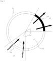
- One side of the penetration pipe 72 on which the first connecting hole 722 is formed and the other side of the penetration pipe 72 on which the second connecting hole 724 is formed may form a predetermined angle.
- the first straight line cl1 passing through the center of the first connecting hole 722 and the second straight line cl2 passing through the center of the second connecting hole 724 may form a predetermined angle ⁇ 1.
- the first straight line cl1 and the second straight line cl2 may be located on the same horizontal plane.
- One side of the penetration pipe 72 on which the first connecting hole 722 is formed and the other side of the penetration pipe 72 on which the second connecting hole 724 may face each other.
- the predetermined angle ⁇ 1 between one side of the penetration pipe 72 on which the first connecting hole 722 is formed and the other side of the penetration pipe 72 on which the second connecting hole 724 is formed may be 180 degrees.
- One side of the penetration pipe 72 on which the first connecting hole 722 is formed and the other side of the penetration pipe 72 on which the second connecting hole 724 is formed may be separated from each other in the circumferential direction, which causes the flow path of the refrigerant to become more complex and lengthens the flow path.
- the refrigerant separation efficiency of the gas-liquid separator 70 may be improved.
- the separation plate 723 may be a part of the penetration pipe 72.
- the separation plate 723 may be formed by cutting a portion of the surface of the penetration pipe 72 and bending the cut portion inward.
- the separation plate 723 may be formed by bending the surface of the penetration pipe 72 into an arch shape pointing upward and bending toward the inside of the penetration pipe 72.
- One side of the separation plate 723 may be connected to the surface of the penetration pipe 72.
- the separation plate 723 and the surface of the penetration pipe 72 may form a predetermined angle.
- the shape of the separation plate 723 may correspond to the shape of the first connecting hole 722.
- the first connecting hole 722 may be formed in an arch shape, and the separation plate 723 may be a plate with a shape corresponding to the arch shape of the first connecting hole.
- the separation plate 723 may be formed with a flat surface.
- the separation plate 723 may guide the mixed refrigerant in the inlet flow path 721 to the first connecting hole 722.
- the separation plate 723 and the first connecting hole 722 may form a predetermined angle.
- the first connecting hole 722 may be formed using a punching process.
- the separation plate 723 may be in close contact with the inner surface of the penetration pipe 72.
- the separation plate 723 may be brazed to the inner surface of the penetration pipe 72.
- the mixed refrigerant in the inlet flow path 721 may not flow through the gap between the separation plate 723 and the inner surface of the penetration pipe 72.
- the separation plate 723 may separate the inlet flow path 721 and the outlet flow path 725.
- the separation plate 723 partitions and separates the inlet flow path 721 and the outlet flow path 725, so that the mixed refrigerant in the inlet flow path 721 flows into the interior of the housing through the first connecting hole 722, and the separated gaseous refrigerant may flow into the outlet flow path through the second connecting hole 724.
- the area of the first connecting hole 722 may be larger than the area of the horizontal cross section of the penetration pipe 72.
- the area of the first connecting hole 722 may be larger than the area of the inlet flow path 721.
- the penetration pipe 72 may include a plurality of first connecting holes 722.
- a plurality of first connecting holes 722 may be arranged in the vertical direction.
- the plurality of first connecting holes 722 may be located in the upper part of the penetration pipe 72.
- the plurality of first connecting holes 722 may be located on one side of the surface of the penetration pipe 72.
- the plurality of first connecting holes 722 may be arranged in the vertical direction on one side of the surface of the penetration pipe 72.
- the total area of the first connecting holes 722 may be increased.
- the pressure loss of the refrigerant flowing into the housing 71 may be reduced, and the operating efficiency of the heat supply apparatus may be improved.
- the separation plate 723 may be located in the first connecting hole 722 located at the lowermost side among the plurality of first connecting holes 722.
- the first connecting hole 722 located at the lowermost side among the plurality of first connecting holes 722 is formed by cutting a portion of the penetration pipe 72
- the separation plate 723 may be formed by bending a cut portion of the penetration pipe 72 toward the inside of the penetration pipe.
- the second connecting hole may be a penetration hole formed in a penetration pipe.
- the area of the second connecting hole may be larger than the area of the horizontal cross section of the penetration pipe.
- the area of the second connecting hole 724 may be larger than the area of the horizontal cross section of the penetration pipe 72.
- the area of the second connecting hole 724 may be larger than the area of the outlet flow path 725.
- the penetration pipe 72 may include a plurality of second connecting holes 724.
- a plurality of second connecting holes 724 may be arranged in the vertical direction.
- the plurality of second connecting holes 724 may be located in the upper part of the penetration pipe 72.
- the plurality of second connecting holes 724 may be located on the other side of the surface of the penetration pipe 72.
- the plurality of second connecting holes 724 may be arranged in the vertical direction on the other side of the surface of the penetration pipe 72.
- the total area of the second connecting holes 724 may be increased.
- the pressure loss of the gaseous refrigerant flowing out through the second connecting hole 724 from the interior of the housing 71 may be reduced, and the operating efficiency of the heat supply apparatus may be improved.
- the gas-liquid separator 70 may be located not only at the front of the compressor 10 but also at other point in the refrigerant circulation cycle. At this time, the gas-liquid separator 70 may discharge liquid refrigerant separated.
- the housing 71 may include a drain pipe 712 through which liquid refrigerant is discharged.
- the drain pipe 712 may be connected to the housing 71.
- the drain pipe 712 may be connected to the bottom surface of the housing 71.
- the drain pipe 712 may be connected to the separation space 710 of the housing 71.
- the drain pipe 712 may be formed in the lower part of the housing 71.
- the drain pipe 712 may be connected to the lower part of the housing 71, allowing liquid refrigerant separated into the lower part of the separation space 710 to flow out from the housing 71 through the drain pipe 712.
- a heat supply apparatus may comprise a compressor compressing refrigerant; a first heat exchanger being connected to the compressor through a refrigerant pipe and exchanging heat between refrigerant and water; a second heat exchanger being connected to the compressor through a refrigerant pipe and exchanging heat between refrigerant and air; and a gas-liquid separator located upstream of the compressor in a refrigerant flow path and separating introduced refrigerant into gaseous refrigerant and liquid refrigerant, wherein the gas-liquid separator includes: a housing; and a penetration pipe passing through one side and the other side of the housing and including an inlet flow path through which mixed refrigerant flows in and an outlet flow path through which gaseous refrigerant flows out, wherein the penetration pipe includes: a first connecting hole formed on a surface and connecting the inlet flow path and the inside of the housing; a second connecting hole formed on a surface and connecting the outlet flow path and
- the penetration pipe may be a single pipe penetrating the housing in one direction.
- the first connecting hole may be formed on one side of the penetration pipe, and the second connecting hole may be formed on the other side of the penetration pipe opposite to one side of the penetration pipe on which the first connecting hole is formed.
- the separation plate may be inclined downward from the other side of the penetration pipe on which the second connecting hole is formed toward one side of the penetration pipe on which the first connecting hole is formed.
- the separation plate may be a part of the penetration pipe, formed by cutting the surface of the penetration pipe and bending the cut portion toward the inside of the penetration pipe.
- the shape of the first connecting hole may be formed to correspond to the shape of the separation plate.
- the separation plate may be a part of the penetration tube, formed by cutting the surface of the penetration pipe in an arch shape pointing upward and bending the cut portion toward the inside of the penetration pipe.
- the separation plate may be in close contact with the inner surface of the penetration pipe and separate the inlet flow path from the outlet flow path.
- the area of the first connecting hole may be larger than the area of the horizontal cross section of the penetration pipe.
- the area of the second connecting hole may be larger than the area of the horizontal cross section of the penetration pipe.
- the first connecting hole may be a plurality of first connecting holes formed on the surface of the penetration pipe.
- the second connecting hole may be a plurality of second connecting holes formed on the surface of the penetration pipe.
- the penetration pipe may be located downstream of the second connecting hole in a refrigerant flow path and include an oil hole located inside the housing.
- the housing may be fixed to the penetration pipe.
- the first connecting hole may be located on an upstream side of the second connecting hole in a refrigerant flow path.
- the gas-liquid separator may comprise: a housing; and a penetration pipe passing through the housing and including an inlet flow path through which mixed refrigerant flows in and an outlet flow path through which gaseous refrigerant flows out, wherein the penetration pipe includes: a first connecting hole formed on a surface and connecting the inlet flow path and the inside of the housing; a second connecting hole formed on a surface and connecting the outlet flow path and the inside of the housing; and a separation plate partitioning the inlet flow path and the outlet flow path.
- the housing may include: a drain pipe at its lower part through which liquid refrigerant is discharged.
- Compressor 60 Second heat exchanger 20: Four-way valve 70: Gas-liquid separator 30: First heat exchanger 80: Refrigerant pipe 40: Expansion device
Landscapes
- Engineering & Computer Science (AREA)
- Physics & Mathematics (AREA)
- Thermal Sciences (AREA)
- Mechanical Engineering (AREA)
- General Engineering & Computer Science (AREA)
- Chemical & Material Sciences (AREA)
- Analytical Chemistry (AREA)
- Power Engineering (AREA)
- Combustion & Propulsion (AREA)
- Heat-Exchange Devices With Radiators And Conduit Assemblies (AREA)
- Heat-Pump Type And Storage Water Heaters (AREA)
Abstract
Description
- The present disclosure relates to a heat supply apparatus and more specifically, to a gas-liquid separator in which an inlet pipe and an outlet pipe are combined into a single unit and a heat supply apparatus including the gas-liquid separator.
- A heating system including a gas boiler supplies a heat source heated by the gas boiler to a load such as underfloor heating or a hot water tank through pipes. The pipes connecting the gas boiler and the load may be disposed buried within the building.
- However, European countries are replacing gas boilers with heat supply apparatuses that utilize heat exchange between water and refrigerant to reduce carbon emissions and minimize the use of refrigerant.
- The gas-liquid separator used in a heat supply apparatus may function to separate mixed refrigerant into gaseous refrigerant and liquid refrigerant and supply them to the operation cycle or to supply the gaseous refrigerant to a compressor.
- The 'accumulator' disclosed in the
Korean patent laid-open publication No. 10-2018-0118397 - A conventional accumulator has a problem in that a separate anti-vibration plate is required to reduce vibration occurring between the pipe and the case and the noise resulting from the vibration.
- Also, the conventional accumulator has a problem in that the accumulator size increases because a screen member for separating gaseous refrigerant and liquid refrigerant, an anti-vibration plate, and a liquid refrigerant inflow prevention plate for storing the liquid refrigerant are disposed inside the case.
- Also, the conventional accumulator has a problem in that the flow of the refrigerant is impeded and pressure loss occurs since a number of components such as a screen member, an anti-vibration plate, and a liquid refrigerant inflow prevention plate are disposed inside the case through which the refrigerant flows.
- Also, the conventional accumulator has a problem in that pressure loss occurs due to a rapid increase in the flow path volume when mixed refrigerant is drawn into an inlet port formed at one end of an inlet pipe and a rapid decrease in the flow path volume when gaseous refrigerant is discharged through a discharge port formed at one end of a connection pipe. These drawbacks of the conventional accumulator lead to decreased operating efficiency of the heat supply apparatus.
- An object of the present disclosure is to provide a gas-liquid separator with improved separation efficiency. Another object of the present disclosure is to provide a gas-liquid separator with reduced vibration and noise. Yet another object of the present disclosure is to provide a heat supply apparatus with improved cooling and heating operation efficiency. Still another object of the present disclosure is to provide a miniaturized gas-liquid separator. Further another object of the present disclosure is to provide a gas-liquid separator with a simplified structure. Yet still another object of the present disclosure is to provide a gas-liquid separator with reduced pressure loss. Yet further another object of the present disclosure is to provide a gas-liquid separator with a simplified manufacturing process and reduced manufacturing costs.
- The technical effects of the present disclosure are not limited to the technical effects described above, and other technical effects not mentioned herein may be understood to those skilled in the art to which the present disclosure belongs from the description below.
- The invention is specified by the independent claim. Preferred embodiments are defined in the dependent claims. According to one aspect of the present disclosure to achieve the object above, a heat supply apparatus may comprise a compressor compressing refrigerant; a first heat exchanger being connected to the compressor through a refrigerant pipe and exchanging heat between refrigerant and water; a second heat exchanger being connected to the compressor through a refrigerant pipe and exchanging heat between refrigerant and air; and a gas-liquid separator for receiving refrigerant flowing from the compressor, the separator separates the received refrigerant into gaseous refrigerant and liquid refrigerant, wherein the gas-liquid separator includes: a housing; and a penetration pipe passing through one side and the other side of the housing and including an inlet flow path through which refrigerant flows in and an outlet flow path through which refrigerant flows out, wherein the penetration pipe includes: a first connecting hole formed on a circumferential surface of the penetration pipe and connecting the inlet flow path and the inside of the housing; a second connecting hole formed on a circumferential surface of the penetration pipe and connecting the outlet flow path and the inside of the housing; and a separation plate partitioning the inlet flow path and the outlet flow path, in which an inlet pipe through which mixed refrigerant flows in and an outlet pipe through which gaseous refrigerant flows out are combined into a single unit.
- The penetration pipe may be a single pipe penetrating the housing in one direction. The penetration pipe is fixed to the housing. The housing is fixed to the penetration pipe.
- The first connecting hole is formed on one side of circumferential surface of the penetration pipe, and the second connecting hole is formed on the other side of circumferential surface of the penetration pipe, the first connecting hole and the second connecting hole are formed in different directions, causing the inflow and outflow paths of refrigerant to be formed in different directions.
- The separation plate is inclined downward from the other side of the penetration pipe on which the second connecting hole is formed toward one side of the penetration pipe on which the first connecting hole is formed, guiding mixed refrigerant in the inlet flow path to the first connecting hole.
- The separation plate may be a part of the penetration pipe, formed by cutting the surface of the penetration pipe and bending the cut portion toward the inside of the penetration pipe.
- The shape of the first connecting hole may be formed to correspond to the shape of the separation plate.
- The separation plate may be a part of the penetration tube, formed by cutting the surface of the penetration pipe in an arch shape pointing upward and bending the cut portion toward the inside of the penetration pipe.
- The separation plate may be in close contact with the inner surface of the penetration pipe and separate the inlet flow path from the outlet flow path to prevent mixed refrigerant in the inlet flow path from flowing directly into the outlet flow path.
- The area of the first connecting hole may be larger than the area of the horizontal cross section of the penetration pipe, which may reduce the flow rate of refrigerant passing through the first connecting hole.
- The area of the second connecting hole may be larger than the area of the horizontal cross section of the penetration pipe, which may reduce the flow rate of the refrigerant passing through the second connecting hole.
- The first connecting hole may be a plurality of first connecting holes formed on the circumferential surface of the penetration pipe, which may increase the total area of the first connecting hole.
- The second connecting hole may be a plurality of second connecting holes formed on the circumferential surface of the penetration pipe, which may increase the total area of the second connecting hole.
- The penetration pipe may be located downstream of the second connecting hole in a refrigerant flow path and include an oil hole located inside the housing, by which oil inside the housing may flow into an outlet flow path.
- The housing may be fixed to the penetration pipe, which may reduce vibration.
- The first connecting hole may be located on an upstream side of the second connecting hole in a refrigerant flow path.
- According to one aspect of the present disclosure to achieve the object above, the gas-liquid separator may comprise: a housing; and a penetration pipe passing through the housing and including an inlet flow path through which refrigerant flows in and an outlet flow path through which refrigerant flows out, wherein the penetration pipe includes: a first connecting hole formed on a circumferential surface of the penetration pipe and connecting the inlet flow path and the inside of the housing; a second connecting hole formed on a circumferential surface of the penetration pipe and connecting the outlet flow path and the inside of the housing; and a separation plate partitioning the inlet flow path and the outlet flow path, in which an inlet pipe through which mixed refrigerant flows in and an outlet pipe through which gaseous refrigerant flows out are combined into a single unit.
- The housing may include: a drain pipe at its lower part through which liquid refrigerant is discharged, allowing separated liquid refrigerant to be moved to another location without being stored in the housing.
- The housing may include: a drain pipe through which refrigerant is discharged, the drain pipe is disposed to discharge refrigerant collected in a lower part of the housing.
- Specifics of other embodiments are provided in the detailed descriptions and drawings below.
- According to at least one of the embodiments of the present disclosure, the structure of a gas-liquid separator may be simplified due to the penetration pipe in which an inlet pipe through which mixed refrigerant flows in and an outlet pipe through which gaseous refrigerant flows out are combined into a single unit. Also, since there is no need for additional configurations to separate mixed refrigerant and reduce vibration, the gas-liquid separator may be miniaturized.
- According to at least one of the embodiments of the present disclosure, since the housing is fixed to a single penetration pipe and moves together with it, vibration and noise generated between the housing and the penetration pipe may be reduced.
- According to at least one of the embodiments of the present disclosure, since the first connecting hole through which mixed refrigerant passes and the second connecting hole through which gaseous refrigerant passes are located opposite to each other, the flow path of refrigerant becomes complex, and the path length is increased, thereby improving the separation efficiency of the refrigerant.
- According to at least one of the embodiments of the present disclosure, since an inclined separator guides the incoming mixed refrigerant, refrigerant circulation within the housing may become smooth, and pressure loss may be reduced.
- According to at least one of the embodiments of the present disclosure, since the separation plate is formed by cutting a portion of the surface of the penetration pipe and bending the cut portion, the manufacturing process of the gas-liquid separator may be simplified, and manufacturing costs may be reduced. Also, the structure of the gas-liquid separator may be simplified.
- According to at least one of the embodiments of the present disclosure, since the first connecting hole, which is an inlet hole through which mixed refrigerant flows in, is formed on the surface of the penetration pipe, the area of the first connecting hole may be increased. As a result, pressure loss may be reduced in the process of introducing mixed refrigerant through the first connecting hole with a larger area. Also, the operating efficiency of the heat supply apparatus may be improved. According to at least one of the embodiments of the present disclosure, since the second connecting hole, which is an outlet hole through which gaseous refrigerant flows out, is formed on the surface of the penetration pipe, the area of the second connecting hole may be increased. As a result, pressure loss may be reduced in the process of introducing gaseous refrigerant through the second connecting hole with a larger area. Also, the operating efficiency of the heat supply apparatus may be improved.
- According to at least one of the embodiments of the present disclosure, the total area of the inlet hole through which mixed refrigerant flows in is increased due to a plurality of first connecting holes, pressure loss may be reduced, and the operating efficiency of the heat supply apparatus may be improved.
- According to at least one of the embodiments of the present disclosure, the total area of the outlet hole through which gaseous refrigerant flows out is increased due to a plurality of second connecting holes, pressure loss may be reduced, and the operating efficiency of the heat supply apparatus may be improved.
- The technical effects of the present disclosure are not limited to the technical effects described above, and other technical effects not mentioned herein may be understood to those skilled in the art to which the present disclosure belongs from the description below.
-
-
FIG. 1 illustrates a cycle of the outdoor unit side of a heat supply apparatus according to one embodiment of the present disclosure. -
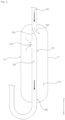
FIG. 2 is a cross-sectional view of a gas-liquid separator according to one embodiment of the present disclosure. -
FIG. 3 is a horizontal cross-sectional view of a penetration pipe according to one embodiment of the present disclosure. -
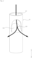
FIG. 4 shows a portion of a penetration pipe according to one embodiment of the present disclosure. -
FIG. 5 shows a portion of a penetration pipe according to another embodiment of the present disclosure. -
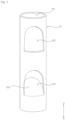
FIG. 6 shows another portion of a penetration pipe according to one embodiment of the present disclosure. -
FIG. 7 shows another portion of a penetration pipe according to another embodiment of the present disclosure. -
FIG. 8 is a cross-sectional view of a gas-liquid separator according to another embodiment of the present disclosure. - In the following, embodiments disclosed in this document will be described in detail with reference to appended drawings. The same or similar constituting elements are given the same reference number irrespective of their drawing symbols, and repeated descriptions thereof will be omitted.
- The suffixes "module" and "unit" for the constituting elements used in the following descriptions are assigned or used interchangeably only for the convenience of writing the present document and do not have separate meanings or roles distinguished from each other.
- Also, it should be understood that the appended drawings are intended only to help understand embodiments disclosed in the present document and do not limit the technical principles and scope of the present disclosure.
- Also, terms including an ordinal number such as first or second may be used to describe various constituting elements of the present disclosure, but the constituting elements should not be limited by these terms. Those terms are used only for the purpose of distinguishing one constituting element from the others.
- If a constituting element is said to be "connected" or "attached" to other constituting element, the former may be connected or attached directly to the other constituting element, but there may be a case in which another constituting element is present between the two constituting elements. On the other hand, if a constituting element is said to be "directly connected" or "directly attached" to other constituting element, it should be understood that there is no other constituting element between the two constituting elements.
- A singular expression should be understood to indicate a plural expression unless otherwise explicitly stated.
- In the present disclosure, the term "include" or "have" is used to indicate existence of an embodied feature, number, step, operation, constituting element, component, or a combination thereof; and should not be understood to preclude the existence or possibility of adding one or more other features, numbers, steps, operations, constituting elements, components, or a combination thereof.
- The direction indications of up (U), down (D), left (Le), right (Ri), front (F), and rear (R) shown in the accompanying drawings are introduced only for the convenience of description, and it should be understood that the technical principles disclosed in the present disclosure are not limited by the indications.
- Referring to
FIG. 1 , theheat supply apparatus 1 may comprise acompressor 10 compressing refrigerant, afirst heat exchanger 30 exchanging heat between refrigerant and water, asecond heat exchanger 60 exchanging heat between refrigerant and outdoor air, and anexpansion device 40 disposed between thefirst heat exchanger 30 and thesecond heat exchanger 60. - The
heat supply apparatus 1 may be an Air to Water Heat Pump (AWHP) that exchanges heat between water and refrigerant. The AWHP may warm up the indoor space or supply hot water by using the heat energy from the outdoor air to warm up the water circulating the indoor space. The AWHP may be mainly used for heating and hot water supply in cold regions. Conversely, AWHP may transfer the heat energy in the indoor space to the refrigerant circulating the outdoor unit through water circulating in the indoor space, and the refrigerant may discharge the heat energy transferred from the indoor space to the outdoor space. Through the above process, AWHP may also cool down indoor spaces or supply cold water. - The
compressor 10, thefirst heat exchanger 30, thesecond heat exchanger 60, and theexpansion device 40 may constitute an outdoor unit. Thewater pipe 90 through which water circulating in the indoor space flows may be connected to thefirst heat exchanger 30. Thewater pipe 90 may include aninlet pipe 92 through which water flows into thefirst heat exchanger 30 and anoutlet pipe 94 through which water is discharged from thefirst heat exchanger 30. Both thewater inlet pipe 92 and thewater outlet pipe 94 may be connected to thefirst heat exchanger 30. Thepump 93 that introduces water into thefirst heat exchanger 30 may be disposed in thewater inlet pipe 92. The water circulating thewater pipe 90 may exchange heat with the refrigerant circulating therefrigerant pipe 80 in thefirst heat exchanger 30. Through the above process, theheat supply apparatus 1 may warm up or cool down the indoor space. - The
heat supply apparatus 1 may include arefrigerant pipe 80 connecting thecompressor 10, thefirst heat exchanger 30, and thesecond heat exchanger 60. Therefrigerant pipe 80 may form a closed circuit. The refrigerant discharged from thecompressor 10 may circulate through therefrigerant pipe 80. - The
refrigerant pipe 80 may include a firstrefrigerant pipe 81 connected to thefirst heat exchanger 30, a secondrefrigerant pipe 82 connecting thefirst heat exchanger 30 and theexpansion device 40, a thirdrefrigerant pipe 83 connecting theexpansion device 40 and thesecond heat exchanger 60, and a fourthrefrigerant pipe 84 connected to thesecond heat exchanger 60. The firstrefrigerant pipe 81 may be located between thecompressor 10 and thefirst heat exchanger 30. The fourthrefrigerant pipe 84 may be located between thecompressor 10 and thesecond heat exchanger 60. - The
heat supply apparatus 1 may include a four-way valve 20 located between thecompressor 10 and thefirst heat exchanger 30. The four-way valve 20 may be located between thecompressor 10 and thesecond heat exchanger 60. The four-way valve 20 may switch therefrigerant pipe 80 depending on the operation mode. In other words, the four-way valve 20 may connect thecompressor 10 and thefirst heat exchanger 30 during the heating operation and connect thecompressor 10 and thesecond heat exchanger 60 during the cooling operation. For example, during the heating operation, the refrigerant discharged from thecompressor 10 may flow to thefirst heat exchanger 30 through the four-way valve 20, and during the cooling operation, the refrigerant discharged from thecompressor 10 may flow to thesecond heat exchanger 60 through the four-way valve 20. - The first
refrigerant pipe 81 may connect thefirst heat exchanger 30 and the four-way valve 20. The fourthrefrigerant pipe 84 may connect thesecond heat exchanger 60 and the four-way valve 20. - The
refrigerant pipe 80 may include aninlet pipe 85 through which the refrigerant flowing into thecompressor 10 flows. Theinlet pipe 85 may be connected to the inlet side of thecompressor 10. Theinlet pipe 85 may connect thecompressor 10 and the four-way valve 20. - The
compressor 10 may be connected to the four-way valve 20. Therefrigerant pipe 80 may include anoutlet pipe 86 through which the refrigerant discharged from thecompressor 10 flows. Theoutlet pipe 86 may be connected to the outlet side of thecompressor 10. Theoutlet pipe 86 may connect thecompressor 10 and the four-way valve 20. - The
heat supply apparatus 1 may include a gas-liquid separator 70 located between the four-way valve 20 and thecompressor 10. The gas-liquid separator 70 may be located in theinlet pipe 85. The gas-liquid separator 70 may be located upstream of thecompressor 10 in the refrigerant flow path. The gas-liquid separator may separate refrigerant flowing into the compressor at the front end of the compressor. For example, during the cooling operation, the gas-liquid separator 70 may separate the mixed refrigerant discharged from thefirst heat exchanger 30 into gaseous refrigerant and liquid refrigerant. Conversely, during the heating operation, the gas-liquid separator 70 may separate the mixed refrigerant discharged from thesecond heat exchanger 60 into gaseous refrigerant and liquid refrigerant. -
FIG. 1 shows the gas-liquid separator 70 located at the front of thecompressor 10; however, the present disclosure is not limited to the specific example, and the gas-liquid separator 70 may be located to separate the mixed refrigerant at any point in the refrigerant circulation cycle. - During the heating operation, the
outlet pipe 86 may be connected to the firstrefrigerant pipe 81 through the four-way valve 20, and theinlet pipe 85 may be connected to the fourthrefrigerant pipe 84 through the four-way valve 20. Through the above process, the refrigerant discharged from thecompressor 10 may flow to thefirst heat exchanger 30. During the cooling operation, theoutlet pipe 86 may be connected to the fourthrefrigerant pipe 84 through the four-way valve 20, and theinlet pipe 85 may be connected to the firstrefrigerant pipe 81 through the four-way valve 20. Through the above process, the refrigerant discharged from thecompressor 10 may flow to thesecond heat exchanger 60. - The
first heat exchanger 30 may be a water-refrigerant heat exchanger 30 that exchanges heat between water and refrigerant. For example, thefirst heat exchanger 30 may be a plate-type heat exchanger through which water and refrigerant flow separately. Water circulating in the indoor space may pass through thefirst heat exchanger 30. The refrigerant circulating in the outdoor unit may pass through thefirst heat exchanger 30. The refrigerant may circulate in the outdoor unit and exchange heat with outdoor air in thesecond heat exchanger 60 and exchange heat with water in thefirst heat exchanger 30. Through the above process, the water circulating in the indoor space may be heated or cooled. During the heating operation, theheat supply apparatus 1 may heat water passing through thefirst heat exchanger 30 to warm up the indoor space or supply hot water. During the cooling operation, theheat supply apparatus 1 may cool the water passing through thefirst heat exchanger 30 to cool down the indoor space or supply cold water. Water and refrigerant passing through thefirst heat exchanger 30 may flow in opposite directions. In other words, water and refrigerant may form countercurrents. - During the heating operation, the refrigerant discharged from the
compressor 10 may be directed to thefirst heat exchanger 30. At this time, thefirst heat exchanger 30 may function as a condenser. The refrigerant that has passed through thefirst heat exchanger 30 may sequentially flow through theexpansion device 40 and thesecond heat exchanger 60. - During the cooling operation, the refrigerant discharged from the
second heat exchanger 60 may be directed to thefirst heat exchanger 30. At this time, thefirst heat exchanger 30 may function as an evaporator. - The
second heat exchanger 60 may be an air-refrigerant heat exchanger 60 that exchanges heat between air and refrigerant. For example, thesecond heat exchanger 60 may be a fin-tube heat exchanger including tubes and fins through which refrigerant flows. Since thefirst heat exchanger 30 and thesecond heat exchanger 60 constitute an outdoor unit, thesecond heat exchanger 60 may exchange heat between outdoor air and refrigerant. - During the heating operation, the refrigerant discharged from the
first heat exchanger 30 may be directed to thesecond heat exchanger 60. At this time, thesecond heat exchanger 60 may function as an evaporator. - During the cooling operation, the refrigerant discharged from the
compressor 10 may be directed to thesecond heat exchanger 60. At this time, thesecond heat exchanger 60 may function as a condenser. - The
expansion device 40 may be located between thefirst heat exchanger 30 and thesecond heat exchanger 60. During the heating operation, the refrigerant may pass through theexpansion device 40 from thefirst heat exchanger 30 to thesecond heat exchanger 60. During the cooling operation, the refrigerant may pass through theexpansion device 40 from thesecond heat exchanger 60 to thefirst heat exchanger 30. Theexpansion device 40 may be located between the secondrefrigerant pipe 82 connected to thefirst heat exchanger 30 and the thirdrefrigerant pipe 83 connected to thesecond heat exchanger 60. Both the secondrefrigerant pipe 82 and the thirdrefrigerant pipe 83 may be connected to theexpansion device 40. For example, during the heating operation, the refrigerant may sequentially pass through the secondrefrigerant pipe 82, theexpansion device 40, and the thirdrefrigerant pipe 83, while, during cooling operation, the refrigerant may sequentially pass through the thirdrefrigerant pipe 83, theexpansion device 40, and the secondrefrigerant pipe 82. - Referring to
FIG. 2 , the gas-liquid separator 70 may include ahousing 71 and a penetration pipe penetrating thehousing 71. - The
housing 71 may form the external shape of the gas-liquid separator 70. Thehousing 71 may include aseparation space 710 where mixed refrigerant is separated. Theseparation space 710 may be an internal space of thehousing 71. For example, thehousing 71 may be formed in a cylindrical shape with a hollow interior. The mixed refrigerant may be separated inside thehousing 71. - The
penetration pipe 72 may penetrate one side and the other side of thehousing 71. Thepenetration pipe 72 may be a single pipe penetrating thehousing 71. For example, the penetratingpipe 72 may be a single pipe that penetrates the center of thehousing 71 in the vertical direction. Asingle penetration pipe 72 may simultaneously perform the functions of an inlet pipe through which refrigerant flows in and an outlet pipe through which refrigerant flows out. In other words, thesingle penetration pipe 72 may be formed by combining an inlet pipe and an outlet pipe into a single unit. By providing thesingle penetration pipe 72 in which the inlet pipe and the outlet pipe are combined into a single unit, the productivity of the gas-liquid separator 70 may be improved, and production costs may be reduced. - Referring to
FIGS. 1 and2 , thepenetration pipe 72 may be connected to therefrigerant pipe 80. For example, one end of thepenetration pipe 72 may be connected to the fourthrefrigerant pipe 84, and the other end may be connected to theinlet pipe 85. Thepenetration pipe 72 may be a part of therefrigerant pipe 80. - The
housing 71 may be fixed to thepenetration pipe 72. Thepenetration pipe 72 may penetrate thehousing 71, and thepenetration pipe 72 and thehousing 71 may be in close contact with each other. Through the structure above, thepenetration pipe 72 and thehousing 71 may move together as a single body. Since thehousing 71 is fixed to thesingle penetration pipe 72, friction noise generated due to vibration of thepenetration pipe 72 against thehousing 71 may be reduced. Also, since thehousing 71 and the single penetratingtube 72 are fixed to each other, thehousing 71 may reduce vibration of the penetratingtube 72. Due to the fixed coupling structure of thehousing 71 and thepenetration pipe 72, no additional configuration is required to reduce vibration and noise, allowing the gas-liquid separator 70 to be miniaturized. - An
inflow flow path 721 through which refrigerant flows in and anoutlet flow path 725 through which refrigerant flows out may be formed in thepenetration pipe 72. For example, mixed refrigerant may flow into thepenetration pipe 72 through theinlet flow path 721, and gaseous refrigerant may flow out from thepenetration pipe 72 through theoutflow flow path 725. Theinlet flow path 721 may be formed on the upstream side of thepenetration pipe 72, and theoutlet flow path 725 may be formed on the downstream side of thepenetration pipe 72. For example, theinlet flow path 721 may be formed in the upper part of thepenetration pipe 72, and theoutlet flow path 725 may be formed in the lower part of thepenetration pipe 72. - The
penetration pipe 72 may include a first connectinghole 722 formed on its surface. The first connectinghole 722 may be formed on one side of thepenetration pipe 72. The first connectinghole 722 may connect theinlet flow path 721 and the interior of thehousing 71. For example, the first connectinghole 722 may connect theinlet flow path 721 and theseparation space 710 of thehousing 71, and mixed refrigerant introduced into theinlet flow path 721 may flow into theseparation space 710 through the first connectinghole 722. - The
penetration pipe 72 may include a second connectinghole 724 formed on its surface. The second connectinghole 724 may be formed on one other side of thepenetration pipe 72. For example, the second connectinghole 724 may be formed on the other side of thepenetration pipe 72 facing one side of thepenetration pipe 72 on which the first connectinghole 722 is formed. The second connectinghole 724 may connect theoutlet flow path 725 and the interior of thehousing 71. For example, the second connectinghole 724 may connect theoutlet flow path 725 and theseparation space 710 of thehousing 71, and mixed refrigerant introduced into theoutlet flow path 725 may flow into theseparation space 710 through the second connectinghole 724. - The first connecting
hole 722 may be located upstream of the second connectinghole 724 in the refrigerant flow path. For example, the first connectinghole 722 may be located above the second connectinghole 724. The mixed refrigerant flowing in through theinlet flow path 721 in the upper part of thepenetration pipe 72 may first flow into the inside of thehousing 71 through the first connectinghole 722, and gaseous refrigerant separated from the inside of thehousing 71 may flow into theoutlet flow path 725 through the second connectinghole 724 located below the first connectinghole 722. The first connectinghole 722 connected to theinlet flow path 721 and the second connectinghole 724 connected to theoutlet flow path 725 may be formed in asingle penetration pipe 72, achieving effective refrigerant separation without involving an additional refrigerant separation structure. - The
penetration pipe 72 may include aseparation plate 723 that partitions theinlet flow path 721 and theoutlet flow path 725. Theseparation plate 723 may be located between the first connectinghole 722 and the second connectinghole 724. Theseparation plate 723 may prevent mixed refrigerant flowing into theinlet flow path 721 from flowing directly into theoutlet flow path 725. The mixed refrigerant flowing into theinlet flow path 721 through theseparation plate 723 may be separated into gaseous refrigerant and liquid refrigerant while passing through the inside of thehousing 71 through the first connectinghole 722, and the gaseous refrigerant may flow out through the second connectinghole 724. By partitioning thesingle penetration pipe 72 into theinlet flow path 721 and theoutlet flow path 725 through theseparation plate 723, the mixed refrigerant may be separated while flowing along a bypass path. The separated liquid refrigerant may accumulate inside thehousing 71 or may be discharged to the outside. - The
separation plate 723 may be inclined. Theseparation plate 723 may be inclined in a direction from the second connectinghole 724 to the first connectinghole 722. Theseparation plate 723 may be tilted around the vertical direction. Theseparation plate 723 may be inclined downward. Theseparation plate 723 may extend in a direction from theinlet flow path 721 to theoutlet flow path 725 as it goes from the second connectinghole 724 to the first connectinghole 722. For example, theseparation plate 723 may be inclined downward from the other side of thepenetration pipe 72 where the second connectinghole 724 is formed toward one side of thepenetration pipe 72 where the first connectinghole 722 is formed. - The
penetration pipe 72 may include anoil hole 726 formed downstream of the second connectinghole 724 in the refrigerant flow path. Theoil hole 726 may be located inside thehousing 71. For example, theoil hole 726 may be located in the lower part of theseparation space 710 of thehousing 71. Oil may flow into theoutlet flow path 725 through theoil hole 726 and join the gaseous refrigerant. The gaseous refrigerant and oil may merge and flow into thecompressor 10. - Referring to
FIG. 3 , the first connectinghole 722 may be formed on one side of thepenetration pipe 72, and the second connectinghole 724 may be formed on the other side of thepenetration pipe 72. - One side of the
penetration pipe 72 on which the first connectinghole 722 is formed and the other side of thepenetration pipe 72 on which the second connectinghole 724 is formed may form a predetermined angle. For example, the first straight line cl1 passing through the center of the first connectinghole 722 and the second straight line cl2 passing through the center of the second connectinghole 724 may form a predetermined angle θ1. At this time, the first straight line cl1 and the second straight line cl2 may be located on the same horizontal plane. One side of thepenetration pipe 72 on which the first connectinghole 722 is formed and the other side of thepenetration pipe 72 on which the second connectinghole 724 may face each other. For example, the predetermined angle θ1 between one side of thepenetration pipe 72 on which the first connectinghole 722 is formed and the other side of thepenetration pipe 72 on which the second connectinghole 724 is formed may be 180 degrees. One side of thepenetration pipe 72 on which the first connectinghole 722 is formed and the other side of thepenetration pipe 72 on which the second connectinghole 724 is formed may be separated from each other in the circumferential direction, which causes the flow path of the refrigerant to become more complex and lengthens the flow path. In other words, since the inflow and outflow directions of refrigerant are different, the refrigerant separation efficiency of the gas-liquid separator 70 may be improved. - With reference to
FIG. 4 , the first connectinghole 722 formed on the surface of one side of thepenetration pipe 72 will be described. - The
separation plate 723 may be a part of thepenetration pipe 72. Theseparation plate 723 may be formed by cutting a portion of the surface of thepenetration pipe 72 and bending the cut portion inward. For example, theseparation plate 723 may be formed by bending the surface of thepenetration pipe 72 into an arch shape pointing upward and bending toward the inside of thepenetration pipe 72. One side of theseparation plate 723 may be connected to the surface of thepenetration pipe 72. Theseparation plate 723 and the surface of thepenetration pipe 72 may form a predetermined angle. - The shape of the
separation plate 723 may correspond to the shape of the first connectinghole 722. For example, the first connectinghole 722 may be formed in an arch shape, and theseparation plate 723 may be a plate with a shape corresponding to the arch shape of the first connecting hole. Theseparation plate 723 may be formed with a flat surface. Theseparation plate 723 may guide the mixed refrigerant in theinlet flow path 721 to the first connectinghole 722. Theseparation plate 723 and the first connectinghole 722 may form a predetermined angle. The first connectinghole 722 may be formed using a punching process. - The
separation plate 723 may be in close contact with the inner surface of thepenetration pipe 72. Theseparation plate 723 may be brazed to the inner surface of thepenetration pipe 72. The mixed refrigerant in theinlet flow path 721 may not flow through the gap between theseparation plate 723 and the inner surface of thepenetration pipe 72. Theseparation plate 723 may separate theinlet flow path 721 and theoutlet flow path 725. Theseparation plate 723 partitions and separates theinlet flow path 721 and theoutlet flow path 725, so that the mixed refrigerant in theinlet flow path 721 flows into the interior of the housing through the first connectinghole 722, and the separated gaseous refrigerant may flow into the outlet flow path through the second connectinghole 724. - The area of the first connecting
hole 722 may be larger than the area of the horizontal cross section of thepenetration pipe 72. The area of the first connectinghole 722 may be larger than the area of theinlet flow path 721. By forming the first connectinghole 722 on the surface of thepenetration pipe 72, the size of the inlet hole through which mixed refrigerant flows into the interior of thehousing 71 may be freely adjusted. Through the structure above, the area of the first connectinghole 722 may be made larger than the area of the horizontal cross section of thepenetration pipe 72, thereby reducing pressure loss caused as mixed refrigerant flows into the interior of thehousing 71. Also, the cooling and heating efficiency of the heat supply apparatus may be improved. - In particular, when low-pressure refrigerant is used in the
heat supply apparatus 1, a problem arises that pressure loss increases due to a high flow rate. Also, there arises a problem that the pressure of the refrigerant further decreases in cold weather. A drop in the refrigerant pressure may lead to a failure of thecompressor 10. By having a large-area first connectinghole 722 on the surface of thepenetration pipe 72, the pressure loss that occurs when the refrigerant flows in and out of the first connectinghole 722 may be reduced, thereby improving the operating efficiency of the heat supply apparatus. - Referring to
FIG. 5 , thepenetration pipe 72 may include a plurality of first connectingholes 722. - A plurality of first connecting
holes 722 may be arranged in the vertical direction. The plurality of first connectingholes 722 may be located in the upper part of thepenetration pipe 72. The plurality of first connectingholes 722 may be located on one side of the surface of thepenetration pipe 72. For example, the plurality of first connectingholes 722 may be arranged in the vertical direction on one side of the surface of thepenetration pipe 72. - By forming a plurality of first connecting
holes 722 on the surface of thepenetration pipe 72, the total area of the first connectingholes 722 may be increased. By increasing the total area of the first connectingholes 722, the pressure loss of the refrigerant flowing into thehousing 71 may be reduced, and the operating efficiency of the heat supply apparatus may be improved. - The
separation plate 723 may be located in the first connectinghole 722 located at the lowermost side among the plurality of first connectingholes 722. In other words, the first connectinghole 722 located at the lowermost side among the plurality of first connectingholes 722 is formed by cutting a portion of thepenetration pipe 72, and theseparation plate 723 may be formed by bending a cut portion of thepenetration pipe 72 toward the inside of the penetration pipe. - With reference to
FIG. 6 , the second connectinghole 724 formed on the surface of the other side of thepenetration pipe 72 will be described. - The second connecting hole may be a penetration hole formed in a penetration pipe.
- The area of the second connecting hole may be larger than the area of the horizontal cross section of the penetration pipe.
- The area of the second connecting
hole 724 may be larger than the area of the horizontal cross section of thepenetration pipe 72. The area of the second connectinghole 724 may be larger than the area of theoutlet flow path 725. By forming the second connectinghole 724 on the surface of thepenetration pipe 72, the size of the outlet hole through which gaseous refrigerant flows into the interior of thepenetration pipe 72 may be freely adjusted. Through the structure above, the area of the second connectinghole 724 may be made larger than the area of the horizontal cross section of thepenetration pipe 72, thereby reducing pressure loss caused as gaseous refrigerant flows into the interior of thepenetration pipe 72. Also, the cooling and heating efficiency of the heat supply apparatus may be improved. - In particular, when low-pressure refrigerant is used in the
heat supply apparatus 1, a problem arises that pressure loss increases due to a high flow rate. Also, there arises a problem that the pressure of the refrigerant further decreases in cold weather. A drop in the refrigerant pressure may lead to a failure of thecompressor 10. By having a large-area second connectinghole 724 on the surface of thepenetration pipe 72, the pressure loss that occurs when the refrigerant flows in and out of the second connectinghole 724 may be reduced, thereby improving the operating efficiency of the heat supply apparatus. - Referring to
FIG. 7 , thepenetration pipe 72 may include a plurality of second connectingholes 724. - A plurality of second connecting
holes 724 may be arranged in the vertical direction. The plurality of second connectingholes 724 may be located in the upper part of thepenetration pipe 72. The plurality of second connectingholes 724 may be located on the other side of the surface of thepenetration pipe 72. For example, the plurality of second connectingholes 724 may be arranged in the vertical direction on the other side of the surface of thepenetration pipe 72. - By forming a plurality of second connecting
holes 722 on the surface of thepenetration pipe 72, the total area of the second connectingholes 724 may be increased. By increasing the total area of the second connectingholes 724, the pressure loss of the gaseous refrigerant flowing out through the second connectinghole 724 from the interior of thehousing 71 may be reduced, and the operating efficiency of the heat supply apparatus may be improved. - With reference to
FIG. 8 , adrain pipe 712 through which liquid refrigerant is discharged will be described. - The gas-
liquid separator 70 may be located not only at the front of thecompressor 10 but also at other point in the refrigerant circulation cycle. At this time, the gas-liquid separator 70 may discharge liquid refrigerant separated. - The
housing 71 may include adrain pipe 712 through which liquid refrigerant is discharged. Thedrain pipe 712 may be connected to thehousing 71. Thedrain pipe 712 may be connected to the bottom surface of thehousing 71. Thedrain pipe 712 may be connected to theseparation space 710 of thehousing 71. Thedrain pipe 712 may be formed in the lower part of thehousing 71. Thedrain pipe 712 may be connected to the lower part of thehousing 71, allowing liquid refrigerant separated into the lower part of theseparation space 710 to flow out from thehousing 71 through thedrain pipe 712. - Referring to
FIGS. 1 to 8 , a heat supply apparatus according to one aspect of the present disclosure may comprise a compressor compressing refrigerant; a first heat exchanger being connected to the compressor through a refrigerant pipe and exchanging heat between refrigerant and water; a second heat exchanger being connected to the compressor through a refrigerant pipe and exchanging heat between refrigerant and air; and a gas-liquid separator located upstream of the compressor in a refrigerant flow path and separating introduced refrigerant into gaseous refrigerant and liquid refrigerant, wherein the gas-liquid separator includes: a housing; and a penetration pipe passing through one side and the other side of the housing and including an inlet flow path through which mixed refrigerant flows in and an outlet flow path through which gaseous refrigerant flows out, wherein the penetration pipe includes: a first connecting hole formed on a surface and connecting the inlet flow path and the inside of the housing; a second connecting hole formed on a surface and connecting the outlet flow path and the inside of the housing; and a separation plate partitioning the inlet flow path and the outlet flow path. - According to another one aspect of the present disclosure, the penetration pipe may be a single pipe penetrating the housing in one direction.
- According to another one aspect of the present disclosure, the first connecting hole may be formed on one side of the penetration pipe, and the second connecting hole may be formed on the other side of the penetration pipe opposite to one side of the penetration pipe on which the first connecting hole is formed.
- According to another one aspect of the present disclosure, the separation plate may be inclined downward from the other side of the penetration pipe on which the second connecting hole is formed toward one side of the penetration pipe on which the first connecting hole is formed.
- According to another one aspect of the present disclosure, the separation plate may be a part of the penetration pipe, formed by cutting the surface of the penetration pipe and bending the cut portion toward the inside of the penetration pipe.
- According to another one aspect of the present disclosure, the shape of the first connecting hole may be formed to correspond to the shape of the separation plate.
- According to another one aspect of the present disclosure, the separation plate may be a part of the penetration tube, formed by cutting the surface of the penetration pipe in an arch shape pointing upward and bending the cut portion toward the inside of the penetration pipe.
- According to another one aspect of the present disclosure, the separation plate may be in close contact with the inner surface of the penetration pipe and separate the inlet flow path from the outlet flow path.
- According to another one aspect of the present disclosure, the area of the first connecting hole may be larger than the area of the horizontal cross section of the penetration pipe.
- According to another one aspect of the present disclosure, the area of the second connecting hole may be larger than the area of the horizontal cross section of the penetration pipe.
- According to another one aspect of the present disclosure, the first connecting hole may be a plurality of first connecting holes formed on the surface of the penetration pipe.
- According to another one aspect of the present disclosure, the second connecting hole may be a plurality of second connecting holes formed on the surface of the penetration pipe.
- According to another one aspect of the present disclosure, the penetration pipe may be located downstream of the second connecting hole in a refrigerant flow path and include an oil hole located inside the housing.
- According to another one aspect of the present disclosure, the housing may be fixed to the penetration pipe.
- According to another one aspect of the present disclosure, the first connecting hole may be located on an upstream side of the second connecting hole in a refrigerant flow path.
- Referring to
FIGS. 1 to 8 , according to one aspect of the present disclosure, the gas-liquid separator may comprise: a housing; and a penetration pipe passing through the housing and including an inlet flow path through which mixed refrigerant flows in and an outlet flow path through which gaseous refrigerant flows out, wherein the penetration pipe includes: a first connecting hole formed on a surface and connecting the inlet flow path and the inside of the housing; a second connecting hole formed on a surface and connecting the outlet flow path and the inside of the housing; and a separation plate partitioning the inlet flow path and the outlet flow path. - According to another one aspect of the present disclosure, the housing may include: a drain pipe at its lower part through which liquid refrigerant is discharged.
- Certain embodiments or other embodiments of the disclosure described above are not mutually exclusive or distinct from each other. Any or all elements of the embodiments of the disclosure described above may be combined with another or combined with each other in configuration or function. For example, a configuration "A" described in one embodiment of the disclosure and the drawings and a configuration "B" described in another embodiment of the disclosure and the drawings may be combined with each other. Namely, although the combination between the configurations is not directly described, the combination is possible except in the case where it is described that the combination is impossible. Although embodiments have been described with reference to a number of illustrative embodiments thereof, it should be understood that numerous other modifications and embodiments can be devised by those skilled in the art that will fall within the scope of the principles of this disclosure. More particularly, various variations and modifications are possible in the component parts and/or arrangements of the subject combination arrangement within the scope of the disclosure, the drawings and the appended claims. In addition to variations and modifications in the component parts and/or arrangements, alternative uses will also be apparent to those skilled in the art.
-
10: Compressor 60: Second heat exchanger 20: Four-way valve 70: Gas-liquid separator 30: First heat exchanger 80: Refrigerant pipe 40: Expansion device
Claims (15)
- A heat supply apparatus (1) comprising:a compressor (10) compressing refrigerant;a first heat exchanger (30) being connected to the compressor (10) through a refrigerant pipe (80) and configured to exchange heat between refrigerant and water;a second heat exchanger (60) being connected to the compressor (10) through a refrigerant pipe (80) and configured to exchange heat between refrigerant and air; anda gas-liquid separator (70) for receiving refrigerant flowing from the compressor (10), the separator (70) configured to separate the received refrigerant into gaseous refrigerant and liquid refrigerant,wherein the gas-liquid separator (70) includes:a housing (71); anda penetration pipe (72) passing through one side and the other side of the housing (71) and including an inlet flow path (721) through which refrigerant flows in and an outlet flow path (725) through which refrigerant flows out,wherein the penetration pipe (72) includes:a first connecting hole (722) formed on a circumferential surface of the penetration pipe (72) and connecting the inlet flow path (721) and the inside of the housing (71);a second connecting hole (724) formed on a circumferential surface of the penetration pipe (72) and connecting the outlet flow path (725) and the inside of the housing (71); anda separation plate (723) partitioning the inlet flow path (721) and the outlet flow path (725).
- The apparatus (1) of claim 1, wherein the penetration pipe (72) is a single pipe penetrating the housing (71) in one direction, and
the penetration pipe (72) is fixed to the housing (71). - The apparatus (1) of claim 1 or 2, wherein the first connecting hole (722) is formed on one side of circumferential surface of the penetration pipe (72), andthe second connecting hole (724) is formed on the other side of circumferential surface of the penetration pipe (72),wherein the first connecting hole (722) and the second connecting hole (724) are formed in different directions.
- The apparatus (1) of claim 1 or 2, wherein the separation plate (723) is inclined downward from the other side of the penetration pipe (72) on which the second connecting hole (724) is formed toward one side of the penetration pipe (72) on which the first connecting hole (722) is formed.
- The apparatus (1) according to any one of claims 1 to 4, wherein the separation plate (723) is a part of the penetration pipe (72), formed by cutting the surface of the penetration pipe (72) and bending the cut portion toward the inside of the penetration pipe (72).
- The apparatus (1) of claim 5, wherein the shape of the first connecting hole (722) is formed to correspond to the shape of the separation plate (723).
- The apparatus (1) according to any one of claims 1 to 6, wherein the separation plate (723) is in close contact with the inner surface of the penetration pipe (72) and separate the inlet flow path (721) from the outlet flow path (725).
- The apparatus (1) according to any one of claims 1 to 7, wherein the area of the first connecting hole (722) is larger than the area of the horizontal cross section of the penetration pipe (72).
- The apparatus (1) according to any one of claims 1 to 8, wherein the area of the second connecting hole (724) is larger than the area of the horizontal cross section of the penetration pipe (72).
- The apparatus (1) according to any one of claims 1 to 9, wherein the first connecting hole (722) is a plurality of first connecting holes (722) formed on the circumferential surface of the penetration pipe (72).
- The apparatus (1) according to any one of claims 1 to 10, wherein the second connecting hole (724) is a plurality of second connecting holes (724) formed on the circumferential surface of the penetration pipe (72).
- The apparatus (1) according to any one of claims 1 to 11, wherein the penetration pipe (72) is located downstream of the second connecting hole (724) in a refrigerant flow path and includes an oil hole (726) located inside the housing (71).
- The apparatus (1) according to any one of claims 1 to 12, wherein the first connecting hole (722) is located on an upstream side of the second connecting hole (724) in a refrigerant flow path.
- A gas-liquid separator (70) comprising:a housing (71); anda penetration pipe (72) passing through the housing (71) and including an inlet flow path (721) through which refrigerant flows in and an outlet flow path (725) through which refrigerant flows out,wherein the penetration pipe (72) includes:a first connecting hole (722) formed on a circumferential surface of the penetration pipe (72) and connecting the inlet flow path (721) and the inside of the housing (71);a second connecting hole (724) formed on a circumferential surface of the penetration pipe (72) and connecting the outlet flow path (725) and the inside of the housing (71); anda separation plate (723) partitioning the inlet flow path (721) and the outlet flow path (725).
- The gas-liquid separator (70) of claim 14, wherein the housing (71) includes: a drain pipe (712) through which refrigerant is discharged,
wherein the drain pipe (712) is disposed to discharge refrigerant collected in a lower part of the housing (71).
Applications Claiming Priority (1)
| Application Number | Priority Date | Filing Date | Title |
|---|---|---|---|
| KR1020230093543A KR20250014103A (en) | 2023-07-19 | 2023-07-19 | Heat supply apparatus |
Publications (2)
| Publication Number | Publication Date |
|---|---|
| EP4495510A2 true EP4495510A2 (en) | 2025-01-22 |
| EP4495510A3 EP4495510A3 (en) | 2025-03-12 |
Family
ID=91959094
Family Applications (1)
| Application Number | Title | Priority Date | Filing Date |
|---|---|---|---|
| EP24189190.2A Pending EP4495510A3 (en) | 2023-07-19 | 2024-07-17 | Heat supply apparatus |
Country Status (3)
| Country | Link |
|---|---|
| US (1) | US20250027695A1 (en) |
| EP (1) | EP4495510A3 (en) |
| KR (1) | KR20250014103A (en) |
Citations (2)
| Publication number | Priority date | Publication date | Assignee | Title |
|---|---|---|---|---|
| JPH0979706A (en) * | 1995-09-11 | 1997-03-28 | Matsushita Refrig Co Ltd | Accumulator |
| KR20180118397A (en) | 2017-04-21 | 2018-10-31 | 엘지전자 주식회사 | Accumulator |
Family Cites Families (20)
| Publication number | Priority date | Publication date | Assignee | Title |
|---|---|---|---|---|
| US5622055A (en) * | 1995-03-22 | 1997-04-22 | Martin Marietta Energy Systems, Inc. | Liquid over-feeding refrigeration system and method with integrated accumulator-expander-heat exchanger |
| JP3339332B2 (en) * | 1996-11-06 | 2002-10-28 | 三菱電機株式会社 | Accumulator, refrigeration cycle device |
| GB2351144B (en) * | 1999-06-11 | 2003-11-05 | Delphi Tech Inc | An accumulator for an air conditioning system |
| CN101310154B (en) * | 2005-11-14 | 2012-12-05 | 日冷工业株式会社 | Gas-liquid separator and refrigerating apparatus equipped therewith |
| KR20070072788A (en) * | 2006-01-02 | 2007-07-05 | 삼성전자주식회사 | Accumulator |
| KR101426998B1 (en) * | 2012-08-02 | 2014-08-06 | 엘지전자 주식회사 | An air conditioner |
| US10775060B2 (en) * | 2013-10-24 | 2020-09-15 | Mitsubishi Electric Corporation | Air-conditioning apparatus |
| KR102198326B1 (en) * | 2013-12-26 | 2021-01-05 | 엘지전자 주식회사 | Air conditioner |
| CN106104171A (en) * | 2014-03-17 | 2016-11-09 | 三菱电机株式会社 | Accumulator and refrigerating circulatory device |
| CN105716307B (en) * | 2014-12-17 | 2018-08-03 | Lg电子株式会社 | Air regulator |
| DE102015107719A1 (en) * | 2015-05-18 | 2016-11-24 | Denso Automotive Deutschland Gmbh | Refrigerant accumulator for a refrigerant circuit and refrigerant circuit with such a refrigerant accumulator |
| CN105485984B (en) * | 2015-12-23 | 2020-06-16 | 宁波奥克斯电气股份有限公司 | Gas-liquid separator of air conditioner and method for reducing noise of indoor unit during refrigeration |
| JP6380515B2 (en) * | 2016-12-05 | 2018-08-29 | 株式会社富士通ゼネラル | Gas-liquid separator and air conditioner equipped with the same |
| JP7002566B2 (en) * | 2017-12-25 | 2022-01-20 | 三菱電機株式会社 | Separator and refrigeration cycle equipment |
| WO2020231804A1 (en) * | 2019-05-15 | 2020-11-19 | Carrier Corporation | A separator |
| CN110455020B (en) * | 2019-07-24 | 2021-08-10 | 海信(山东)空调有限公司 | Flash tank, air-supplying and enthalpy-increasing air conditioning system and control method thereof |
| CN112665228B (en) * | 2019-10-15 | 2022-04-05 | 浙江盾安禾田金属有限公司 | Gas-liquid separator and compression system |
| KR102937859B1 (en) * | 2020-07-13 | 2026-03-10 | 엘지전자 주식회사 | Air conditioner |
| CN114608226B (en) * | 2020-12-08 | 2024-07-23 | 合肥美的暖通设备有限公司 | Oil separator and air conditioner outdoor unit |
| CN113266969B (en) * | 2021-05-08 | 2022-09-09 | 三花控股集团有限公司 | Gas-liquid separator |
-
2023
- 2023-07-19 KR KR1020230093543A patent/KR20250014103A/en active Pending
-
2024
- 2024-07-17 EP EP24189190.2A patent/EP4495510A3/en active Pending
- 2024-07-17 US US18/775,618 patent/US20250027695A1/en active Pending
Patent Citations (2)
| Publication number | Priority date | Publication date | Assignee | Title |
|---|---|---|---|---|
| JPH0979706A (en) * | 1995-09-11 | 1997-03-28 | Matsushita Refrig Co Ltd | Accumulator |
| KR20180118397A (en) | 2017-04-21 | 2018-10-31 | 엘지전자 주식회사 | Accumulator |
Also Published As
| Publication number | Publication date |
|---|---|
| KR20250014103A (en) | 2025-02-03 |
| EP4495510A3 (en) | 2025-03-12 |
| US20250027695A1 (en) | 2025-01-23 |
Similar Documents
| Publication | Publication Date | Title |
|---|---|---|
| JP6923051B2 (en) | Heat exchanger and heat pump equipment | |
| US11181328B2 (en) | Heat exchanger and air conditioner | |
| US10041710B2 (en) | Heat exchanger and air conditioner | |
| KR101786965B1 (en) | Header and heat exchanger having the same | |
| KR101462173B1 (en) | Heat exchanger | |
| JP7348308B2 (en) | Heat exchanger and refrigeration cycle equipment | |
| CN112888910B (en) | Heat exchanger and refrigeration cycle device | |
| US11181305B2 (en) | Heat exchanger or refrigeration apparatus including heat exchanger | |
| WO2021219026A1 (en) | Gas-liquid separation device and thermal management system | |
| CN112432402B (en) | Gas-liquid separator and thermal management system | |
| CN115280092A (en) | Heat exchanger | |
| CN115298507B (en) | Heat Exchanger | |
| US20230106747A1 (en) | Heat exchanger or refrigeration apparatus including heat exchanger | |
| EP2982924A1 (en) | Heat exchanger | |
| CN112432401A (en) | Gas-liquid separator | |
| EP4495510A2 (en) | Heat supply apparatus | |
| KR20120043914A (en) | Air conditioning system | |
| US20080190122A1 (en) | Accumulator Integration with Heat Exchanger Header | |
| KR102063630B1 (en) | Outdoor Heat exchanger | |
| CN214536804U (en) | Heat exchanger and kitchen air conditioning system applying same | |
| CN115371309B (en) | Gas-liquid separator and thermal management system | |
| JP2018048766A (en) | Parallel flow heat exchanger and refrigeration cycle device | |
| JP7667512B2 (en) | Heat exchangers and refrigeration equipment | |
| EP4700321A1 (en) | Heat exchanger and refrigeration device | |
| WO2019078066A1 (en) | Heat exchanger and air conditioning device with same |
Legal Events
| Date | Code | Title | Description |
|---|---|---|---|
| PUAI | Public reference made under article 153(3) epc to a published international application that has entered the european phase |
Free format text: ORIGINAL CODE: 0009012 |
|
| STAA | Information on the status of an ep patent application or granted ep patent |
Free format text: STATUS: REQUEST FOR EXAMINATION WAS MADE |
|
| 17P | Request for examination filed |
Effective date: 20240817 |
|
| AK | Designated contracting states |
Kind code of ref document: A2 Designated state(s): AL AT BE BG CH CY CZ DE DK EE ES FI FR GB GR HR HU IE IS IT LI LT LU LV MC ME MK MT NL NO PL PT RO RS SE SI SK SM TR |
|
| PUAL | Search report despatched |
Free format text: ORIGINAL CODE: 0009013 |
|
| AK | Designated contracting states |
Kind code of ref document: A3 Designated state(s): AL AT BE BG CH CY CZ DE DK EE ES FI FR GB GR HR HU IE IS IT LI LT LU LV MC ME MK MT NL NO PL PT RO RS SE SI SK SM TR |
|
| RIC1 | Information provided on ipc code assigned before grant |
Ipc: F25B 43/00 20060101ALI20250205BHEP Ipc: F25B 13/00 20060101AFI20250205BHEP |
|
| STAA | Information on the status of an ep patent application or granted ep patent |
Free format text: STATUS: EXAMINATION IS IN PROGRESS |
|
| 17Q | First examination report despatched |
Effective date: 20260303 |