EP4495482A1 - Gas tap with safety valve for a gas cooking appliance - Google Patents
Gas tap with safety valve for a gas cooking appliance Download PDFInfo
- Publication number
- EP4495482A1 EP4495482A1 EP23382761.7A EP23382761A EP4495482A1 EP 4495482 A1 EP4495482 A1 EP 4495482A1 EP 23382761 A EP23382761 A EP 23382761A EP 4495482 A1 EP4495482 A1 EP 4495482A1
- Authority
- EP
- European Patent Office
- Prior art keywords
- actuator element
- gas
- safety valve
- gas tap
- motor
- Prior art date
- Legal status (The legal status is an assumption and is not a legal conclusion. Google has not performed a legal analysis and makes no representation as to the accuracy of the status listed.)
- Granted
Links
Images



Classifications
-
- F—MECHANICAL ENGINEERING; LIGHTING; HEATING; WEAPONS; BLASTING
- F23—COMBUSTION APPARATUS; COMBUSTION PROCESSES
- F23N—REGULATING OR CONTROLLING COMBUSTION
- F23N1/00—Regulating fuel supply
-
- F—MECHANICAL ENGINEERING; LIGHTING; HEATING; WEAPONS; BLASTING
- F23—COMBUSTION APPARATUS; COMBUSTION PROCESSES
- F23N—REGULATING OR CONTROLLING COMBUSTION
- F23N1/00—Regulating fuel supply
- F23N1/007—Regulating fuel supply using mechanical means
-
- F—MECHANICAL ENGINEERING; LIGHTING; HEATING; WEAPONS; BLASTING
- F16—ENGINEERING ELEMENTS AND UNITS; GENERAL MEASURES FOR PRODUCING AND MAINTAINING EFFECTIVE FUNCTIONING OF MACHINES OR INSTALLATIONS; THERMAL INSULATION IN GENERAL
- F16K—VALVES; TAPS; COCKS; ACTUATING-FLOATS; DEVICES FOR VENTING OR AERATING
- F16K11/00—Multiple-way valves, e.g. mixing valves; Pipe fittings incorporating such valves
- F16K11/02—Multiple-way valves, e.g. mixing valves; Pipe fittings incorporating such valves with all movable sealing faces moving as one unit
- F16K11/06—Multiple-way valves, e.g. mixing valves; Pipe fittings incorporating such valves with all movable sealing faces moving as one unit comprising only sliding valves, i.e. sliding closure elements
- F16K11/072—Multiple-way valves, e.g. mixing valves; Pipe fittings incorporating such valves with all movable sealing faces moving as one unit comprising only sliding valves, i.e. sliding closure elements with pivoted closure members
- F16K11/074—Multiple-way valves, e.g. mixing valves; Pipe fittings incorporating such valves with all movable sealing faces moving as one unit comprising only sliding valves, i.e. sliding closure elements with pivoted closure members with flat sealing faces
-
- F—MECHANICAL ENGINEERING; LIGHTING; HEATING; WEAPONS; BLASTING
- F16—ENGINEERING ELEMENTS AND UNITS; GENERAL MEASURES FOR PRODUCING AND MAINTAINING EFFECTIVE FUNCTIONING OF MACHINES OR INSTALLATIONS; THERMAL INSULATION IN GENERAL
- F16K—VALVES; TAPS; COCKS; ACTUATING-FLOATS; DEVICES FOR VENTING OR AERATING
- F16K27/00—Construction of housing; Use of materials therefor
- F16K27/04—Construction of housing; Use of materials therefor of sliding valves
- F16K27/044—Construction of housing; Use of materials therefor of sliding valves slide valves with flat obturating members
- F16K27/045—Construction of housing; Use of materials therefor of sliding valves slide valves with flat obturating members with pivotal obturating members
-
- F—MECHANICAL ENGINEERING; LIGHTING; HEATING; WEAPONS; BLASTING
- F16—ENGINEERING ELEMENTS AND UNITS; GENERAL MEASURES FOR PRODUCING AND MAINTAINING EFFECTIVE FUNCTIONING OF MACHINES OR INSTALLATIONS; THERMAL INSULATION IN GENERAL
- F16K—VALVES; TAPS; COCKS; ACTUATING-FLOATS; DEVICES FOR VENTING OR AERATING
- F16K31/00—Actuating devices; Operating means; Releasing devices
- F16K31/02—Actuating devices; Operating means; Releasing devices electric; magnetic
- F16K31/04—Actuating devices; Operating means; Releasing devices electric; magnetic using a motor
- F16K31/041—Actuating devices; Operating means; Releasing devices electric; magnetic using a motor for rotating valves
- F16K31/043—Actuating devices; Operating means; Releasing devices electric; magnetic using a motor for rotating valves characterised by mechanical means between the motor and the valve, e.g. lost motion means reducing backlash, clutches, brakes or return means
-
- F—MECHANICAL ENGINEERING; LIGHTING; HEATING; WEAPONS; BLASTING
- F16—ENGINEERING ELEMENTS AND UNITS; GENERAL MEASURES FOR PRODUCING AND MAINTAINING EFFECTIVE FUNCTIONING OF MACHINES OR INSTALLATIONS; THERMAL INSULATION IN GENERAL
- F16K—VALVES; TAPS; COCKS; ACTUATING-FLOATS; DEVICES FOR VENTING OR AERATING
- F16K31/00—Actuating devices; Operating means; Releasing devices
- F16K31/44—Mechanical actuating means
- F16K31/53—Mechanical actuating means with toothed gearing
- F16K31/535—Mechanical actuating means with toothed gearing for rotating valves
-
- F—MECHANICAL ENGINEERING; LIGHTING; HEATING; WEAPONS; BLASTING
- F24—HEATING; RANGES; VENTILATING
- F24C—DOMESTIC STOVES OR RANGES ; DETAILS OF DOMESTIC STOVES OR RANGES, OF GENERAL APPLICATION
- F24C3/00—Stoves or ranges for gaseous fuels
- F24C3/12—Arrangement or mounting of control or safety devices
- F24C3/126—Arrangement or mounting of control or safety devices on ranges
-
- F—MECHANICAL ENGINEERING; LIGHTING; HEATING; WEAPONS; BLASTING
- F23—COMBUSTION APPARATUS; COMBUSTION PROCESSES
- F23N—REGULATING OR CONTROLLING COMBUSTION
- F23N2235/00—Valves, nozzles or pumps
- F23N2235/12—Fuel valves
- F23N2235/18—Groups of two or more valves
-
- F—MECHANICAL ENGINEERING; LIGHTING; HEATING; WEAPONS; BLASTING
- F23—COMBUSTION APPARATUS; COMBUSTION PROCESSES
- F23N—REGULATING OR CONTROLLING COMBUSTION
- F23N2235/00—Valves, nozzles or pumps
- F23N2235/12—Fuel valves
- F23N2235/24—Valve details
-
- F—MECHANICAL ENGINEERING; LIGHTING; HEATING; WEAPONS; BLASTING
- F23—COMBUSTION APPARATUS; COMBUSTION PROCESSES
- F23N—REGULATING OR CONTROLLING COMBUSTION
- F23N2241/00—Applications
- F23N2241/08—Household apparatus
Definitions
- the present invention relates to gas taps with a safety valve for gas cooking appliances and to gas appliances incorporating said gas taps.
- JP380357B2 relates to a gas tap with a safety valve comprising a body comprising a gas inlet conduit fluidically connected with the safety valve, a gas outlet conduit, a housing fluidically connected with the safety valve and with said outlet conduit, and a regulating disc arranged in said housing and configured to regulate the gas flow.
- the gas tap comprises a motor and a gear system arranged outside the body, and a transmission shaft arranged at the outlet of the gear system and introducing adapted movement of the motor in the body.
- the gas tap comprises a cam coupled to said transmission shaft, said cam being configured to act on the safety valve and open it by means of its rotation.
- the regulating disc is also coupled to the transmission shaft.
- the object of the invention is to provide a gas tap with a safety valve for a gas cooking appliance and a gas cooking appliance incorporating said gas tap, as defined in the claims.
- a first aspect of the invention relates to a gas tap with a safety valve for a gas cooking appliance.
- the gas tap with a safety valve comprises a body comprising a gas inlet conduit fluidically connected with the safety valve, at least one gas outlet conduit, and a housing fluidically connected with the safety valve and with said at least one outlet conduit. Furthermore the housing comprises a contact surface comprising at least one outlet hole fluidically connected with said at least one outlet conduit.
- the gas tap comprises a regulating disc comprising at least one regulation opening and arranged in the housing of the body over the contact surface, the regulating disc being configured to regulate, by means of its rotation, the incoming gas flow from the safety valve to said at least one outlet conduit.
- the gas tap also comprises an actuator element housed in the body and configured to open the safety valve by means of its rotation.
- the gas tap comprises a motor comprising an output shaft, and a gear coupled to the shaft of the motor and configured to transmit the movement of the motor to the regulating disc.
- the actuator element is a wheel comprising a plurality of teeth, the actuator element being part of the gear.
- the actuator element is an at least partially toothed wheel that is part of the gear that transmits the rotation of the shaft of the motor to the regulating disc.
- the actuator element is configured to open the safety valve by means of its rotation. The actuator element thereby performs a dual function, and a more compact actuation mechanism of the tap with fewer parts can be obtained.
- a second aspect of the invention relates to a gas cooking appliance comprising at least one gas tap like the one described in the first aspect of the invention.
- a first aspect of the invention relates to a gas tap 1 with a safety valve 20 for a gas cooking appliance.
- the gas tap 1 of the invention comprises a body 10 comprising a gas inlet conduit 11 fluidically connected with the safety valve 20, at least one gas outlet conduit 12, 13, and a housing 14 fluidically connected with the safety valve 20 and with said at least one outlet conduit 12, 13.
- the housing 14 comprises a contact surface 140 comprising at least one outlet hole 120, 130 fluidically connected with said at least one outlet conduit 12, 13.
- the gas tap 1 comprises between one and three outlet conduits.
- the safety valve 20 is a normally closed solenoid valve housed in a safety conduit 19 of the body 10, said safety conduit 19 being connected with the gas inlet conduit 11.
- Said safety valve 20 comprises a plug 21, said plug 21 being configured to be displaced between a closed position in which it is arranged on a seating 18 of the safety conduit 19, preventing the gas flow, and a passage position in which the plug 21 is separated from the seating 18, allowing the gas flow from the inlet conduit 11 to the housing 14 through a passage opening 180 connecting the safety conduit 19 with the housing 14 of the body 10.
- the safety valve 20 when the plug 21 is arranged in the closed position, the safety valve 20 is considered to be closed, whereas when the plug 21 is arranged in the passage position, the safety valve 20 is considered to be open.
- the safety valve 20 also comprises a spring 22 which causes the plug 21 to be in the closed position.
- the initial opening of the safety valve 20 is performed by mechanically pushing the plug element 21, separating it from the seating 18, and preferably, during a brief predetermined period of time, the safety valve 20 is electronically powered to keep the safety valve 20 open. Once said period has passed, while the burner associated with the gas tap 1 is on, the corresponding thermocouple keeps the safety valve energized and, accordingly, the plug 21 in the passage position.
- the gas tap 1 also comprises a regulating disc 30 comprising at least one regulation opening 31a, 31b.
- the regulating disc 30 is arranged in the housing 14 of the body 10 over the contact surface 140.
- the regulating disc 30 is configured to regulate, by means of rotating same, the incoming gas flow from the safety valve 20 to said at least one outlet conduit 12, 13.
- the regulating disc 30 comprises a series of regulation openings 31a, 31b per outlet conduit 12, 13 which allow regulating the gas flow between the housing 14 and the corresponding outlet conduit 12, 13 by means of the rotation of the regulating disc 30.
- the regulating disc may comprise a single regulation opening per outlet conduit. The regulation of the gas flow occurs when at least one regulation opening 31a, 31b and the corresponding outlet hole 120, 130 are arranged fluidically connected.
- the gas tap 1 comprises a motor 80, preferably a BLDC motor, comprising an output shaft 81.
- a stepper motor or any other low torque motor could also be used.
- the gas tap 1 also comprises a gear coupled to the shaft 81 of the motor 80 and configured to transmit the movement of the motor 80 to the regulating disc 30.
- the gas tap 1 comprises an actuator element 40 housed in the body 10 and configured to open the safety valve 20 by means of its rotation. Furthermore, the actuator element 40 is a wheel comprising a plurality of teeth 41, the actuator element 40 being part of the gear. Preferably the plurality of teeth 41 are arranged on at least part of the perimeter of the actuator element 40.
- the actuator element 40 is an at least partially toothed wheel which, in addition to being part of the gear that transmits the rotation of the shaft 81 of the motor 80 to the regulating disc 30, is also configured to open the safety valve 20 by means of its rotation.
- the actuator element 40 thereby performs a dual function, and an actuation mechanism of the gas tap 1 with fewer parts, and which is therefore simpler and more compact, can be obtained.
- the gas tap 1 of the invention is a motor-driven gas tap 1 which, by means of the rotation of the motor 80, can on one hand mechanically open the safety valve 20, and on the other hand regulate the gas flow from the inlet conduit 11 to said at least one outlet conduit 12, 13.
- the motor 80 is arranged outside the housing 14 of the body 10, i.e., the motor 80 is arranged outside the area through which the gas circulates.
- the arrangement of the motor 80 outside the housing 14 of the body 10 facilitates the tightness of the gas tap 1, given that in the event that the motor is inside the housing of the body, the cavity to be isolated would increase considerably, and furthermore a system would have to be designed to assure the isolation of the power cables and control of the motor.
- the gear comprises a worm screw 60, said worm screw 60 being coupled to the shaft 81 of the motor 80, and said worm screw 60 engaging with the teeth 41 of the actuator element 40.
- the rotation shaft 600 of the worm screw 60 is arranged perpendicular with respect to the rotation shaft 402 of the actuator element 40.
- the body 10 comprises an inlet hole which allows introducing the worm screw 60 inside the body 10.
- the worm screw 60 thereby comprises a first end arranged outside the body 10, said first end being coupled to the shaft 81 of the motor, and the rest of the worm screw 60 being housed in the body 10.
- the gas tap 1 comprises a lip seal 56 arranged surrounding the worm screw 60 and supported against the body 10 to seal the inlet hole and thus maintain the tightness of said inlet port.
- the tightness required is obtained with the lip seal 56, exercising a friction force on the worm screw 60 that is considerably less than force that would be exerted on said worm screw in the case of using an O-ring commonly used in motor-driven gas taps in which the motor is arranged outside the housing of the body.
- This type of gear known as a "worm gear” allows reducing the output speed of the motor 80 by increasing the torque in the transmission.
- a motor 80 with a low output torque can thereby be used, obtaining as a result of the type of gear the torque necessary in the actuator element 40 to cause the opening of the safety valve 20.
- the motors with a low output torque are usually less expensive, so the use of this type of gear, also in addition to the dual function of the actuator element 40 which allows using fewer parts, makes the gas tap 1 of the invention a less expensive and simpler solution.
- this type of "worm screw-worm screw wheel” gear requires less space and achieves a greater reduction of speed-increase of output torque than in a gear with parallel shafts, such that the solution of the invention requires a lower number of parts in the transmission system, obtaining a less complex gas tap and facilitating the manufacture, assembly, and operation thereof.
- the gas tap 1 comprises at least one bushing 54, 55 with little clearance surrounding a part of the worm screw 60, a bushing 54 preferably being arranged after the lip seal 56.
- Said at least one bushing 54, 55 is housed in a corresponding retention housing of the body 10, such that said at least one bushing 54, 55 keeps the worm screw 60 centered and prevents radial displacement thereof.
- the gas tap 1 comprises a first bushing 54 arranged in a first part 61 of the worm screw 60 and a second bushing 55 arranged in a second part 62 of the worm screw 60, the toothed part 63 of the worm screw 60 being arranged between the first part 61 and the second part 62.
- the gas tap 1 may comprise an axial stop 57 arranged in the body 1, the worm screw 60 comprising a notch 65 cooperating with said axial stop 57 such that the possible axial displacements of the worm screw 60 are also minimized.
- the actuator element 40 comprises a protrusion 42 configured to act indirectly on the plug element 21 of the safety valve 20.
- the protrusion 42 is arranged on the perimeter of the actuator element 40 and protrudes radially with respect to the perimeter of said actuator element 40.
- the protrusion 42 can also be used to define a zero position of the regulating disc 30.
- the protrusion 42 can cooperate with an abutment wall of the body 10 such that when said zero position is to be determined, the actuator element 40 is rotated in a search for zero direction, determining the zero position when the protrusion 42 abuts with the abutment wall that prevents the actuator element 40 from being able to continue rotating in said direction.
- the gas tap 1 comprises a lever 70 arranged in the housing 14 and rotationally fixed to the body 10 by means of a rotation shaft 73.
- the lever 70 is configured to act on the plug element 21 of the safety valve 20 when the rotation of the actuator element 40 causes the protrusion 42 to act on the lever 70.
- the lever 70 comprises a first radial prolongation 71 configured to cooperate with the actuator element 40, and a second radial prolongation 72 configured to cooperate with the safety valve 20, the rotation shaft 73 being arranged between both radial prolongations 71, 72.
- the second radial prolongation 72 of the lever 70 is configured to act on the plug element 21 of the safety valve 20, opening said safety valve 20 when the protrusion 42 of the actuator element 40 pushes the first radial prolongation 71 of the lever 70.
- the lever 70 is configured to rotate between a standby position and a pushing position in which the second radial prolongation 72 of the lever 70 goes through the passage opening 180, thus separating the plug 21 from the seating 18, allowing the passage of gas from the inlet conduit 11 to the housing 14 through the passage opening 180.
- the lever 70 amplifies the force transmitted by the actuator element 40 to the plug 21 such that its use as an intermediate element allows exerting the force needed to open the safety valve 20 with a lower torque of the actuator element 40 than if said actuator element 40 were to act directly on the plug 21.
- the use of the lever 70 thereby causes the torque required of the motor 80 to be able to open the safety valve 20 to be lower.
- the at least one regulation opening 31a, 31b of the regulating disc 30 is arranged such that when the protrusion 42 of the actuator element 40 is arranged in angular positions of the circular sector in which said protrusion 42 acts on the lever 70, said at least one regulation opening 31a, 31b does not coincide with the at least one outlet hole 120, 130, such that it is ensured that there will be no gas flow while the protrusion 42 acts on the lever 70, i.e., while the plug 21 of the safety valve 20 is operated mechanically, such that in the event of a malfunction, if the actuator element 40 were to be blocked in an angular position in which the plug 21 is operated mechanically by the lever 70, it is ensured that there will be no gas leak.
- the regulating disc 30 is coupled to the actuator element 40 such that both parts rotate integrally, the actuator element 40 being what directly transmits the rotation to the regulating disc 30.
- the actuator element 40 comprises a central protrusion 43 and the regulating disc 30 comprises a central hole 32 with a shape complementary to the central protrusion 43 of the actuator element 40, the central protrusion 43 being housed in the central hole 32 such that both parts rotate integrally.
- the regulating disc can be integrated in the actuator element itself.
- the body 10 comprises a central hole 16 in which a shaft 51 is arranged, and the central protrusion 43 of the actuator element comprises a central hole 430, the shaft 51 going through said central hole 430 such that the actuator element 40 is configured to rotate with respect to said shaft 51.
- the actuator element 40 comprises at least one pressure element 44 that protrudes with respect to the surface 400 of the actuator element 40 which is arranged facing the regulating disc 30, said at least one pressure element 44 being configured to press the regulating disc 30 against the contact surface 140.
- the actuator element 40 also has the function of ensuring proper support of the regulating disc 30 over the contact surface 140 of the housing 14.
- the gas tap 1 comprises a sealing gasket 50 housed in the contact surface 140 surrounding the at least one outlet hole 120, 130, the regulating disc 30 being arranged in a supported manner, pressing on said sealing gasket 50, the sealing gasket 50 ensuring the tightness between the regulating disc 30 and the contact surface 140, such that it is assured that there will only be gas flow to the at least one outlet conduit 12, 13 when at least one regulation opening 31a, 31b and the corresponding outlet hole 120, 130 are arranged fluidically connected.
- the actuator element 40 is axially retained by means of a spring 52 that pushes the actuator element 40 at one of its ends, the other end of the spring 52 being supported in a cover 15 attached to the body 10 that closes the housing 14 of the body 10 in a leak-tight manner.
- the gas tap 1 comprises a lower support part 58 manufactured in a low friction material, for example nylon, which is arranged between the actuator element 40 and the spring 52.
- the gas tap 1 also comprises an upper support part 58 which is arranged between the cover 15 and the spring 52.
- the gas tap 1 comprises a second sealing gasket 53 arranged between the body 10 and the cover 15.
- a second aspect of the invention relates to a gas cooking appliance comprising at least one gas tap 1 like the one described in the first aspect of the invention.
- Figures 1 to 9 show a gas tap 1 according to a preferred embodiment of the invention.
- the gas tap 1 comprises a body 10 comprising a safety conduit 19 in which a safety valve 20 is arranged, and a gas inlet conduit 11 fluidically connected with said safety conduit 19.
- the body 10 also comprises two gas outlet conduits 12, 13, and a housing 14 fluidically connected with the safety conduit 19 and with said outlet conduits 12, 13.
- the housing 14 comprises a contact surface 140 comprising two outlet holes 120, 130, each outlet hole 120, 130 being fluidically connected with the outlet conduit 12, 13 corresponding.
- the safety conduit 19 comprises a seating 18 comprising a passage opening 180 connecting the safety conduit 19 with the housing 14 of the body 10.
- the safety valve 20 is a normally closed solenoid valve.
- the safety valve 20 comprises a plug 21 configured to be displaced between a closed position in which the plug 21 is arranged on the seating 18 of the safety conduit 19, preventing the gas flow, and a passage position in which the plug 21 is separated from the seating 18, allowing the gas flow from the inlet conduit 11 to the housing 14 through a passage opening 180.
- the safety valve 20 comprises a spring 22 which causes the plug 21 to be in the closed position.
- the initial opening of the safety valve 20 is performed by mechanically pushing the plug element 21, separating it from the seating 18 and during a brief predetermined period of time, the safety valve 20 is electronically powered to keep the safety valve 20 open. Once said period has passed, while the burner associated with the gas tap is on, the corresponding thermocouple keeps the safety valve 20 energized and, accordingly, the plug 21 in the passage position.
- the gas tap 1 of the preferred embodiment also comprises a regulating disc 30 arranged in the housing 14 of the body 10 over the contact surface 140.
- the regulating disc 30 is configured to regulate, by means of its rotation, the incoming gas flow from the inlet conduit 11, through the safety valve 20, to the outlet conduits 12, 13.
- the regulating disc 30 comprises a first series of regulation openings 31a to regulate the gas flow from the housing 14 of the body 10 to the first outlet conduit 12 through the first outlet hole 120, and a second series of regulation openings 31b to regulate the gas flow from the housing 14 of the body 10 to the second outlet conduit 13 through the second outlet hole 130.
- the openings of the series of regulation openings 31a, 31b form two rows with a radial shape having a different radius, the radius of the first series of regulation openings 31a being larger than the second series of regulation openings 31b.
- a specific number of openings of the series of regulation openings 31a, 31b of the regulating disc 30 overlap the outlet holes 120, 130.
- the gas tap 1 of the preferred embodiment also comprises a BLDC motor 80 arranged outside the housing 14 of the body 10.
- the motor 80 comprises an output shaft 81.
- the gas tap 1 also comprises a gear coupled to the shaft 81 of the motor 80 and configured to transmit the movement of the motor 80 to the regulating disc 30.
- the gas tap 1 of the preferred embodiment also comprises an actuator element 40 housed in the body 10 and configured to open the safety valve 20 by means of its rotation.
- the actuator element 40 is a wheel comprising a plurality of teeth 41 arranged on part of the perimeter of the actuator element 40, the actuator element 40 being part of the gear.
- the actuator element 40 is a partially toothed wheel which, in addition to being part of the gear that transmits the rotation of the shaft 81 of the motor 80 to the regulating disc 30, is also configured to open the safety valve 20 by means of its rotation.
- the gear is a "worm gear”.
- the gear comprises a worm screw 60 coupled to the shaft 81 of the motor 80, said worm screw 60 engaging with the teeth 41 of the actuator element 40.
- the body 10 comprises an inlet hole which allows introducing the worm screw 60 inside the body 10.
- the worm screw 60 thereby comprises a first end arranged outside the body 10, said first end being coupled to the shaft 81 of the motor, and the rest of the worm screw 60 being housed in the body 10, as observed in detail in Figure 3 .
- the gas tap 1 comprises a lip seal 56 arranged surrounding the worm screw 60 and supported against the body 10 to seal the inlet hole and thus maintain the tightness of said inlet port.
- the gas tap 1 of the preferred embodiment comprises a first bushing 54 arranged after the lip seal 56 and surrounding a first part 61 of the worm screw 60, and a second bushing 54 arranged surrounding a second part 62 of the worm screw 60, the toothed part 63 of the worm screw 60 being arranged between the first part 61 and the second part 62.
- Said bushings 54, 55 are housed in a respective retention housing of the body 10 such that said bushings 54, 55 keep the worm screw 60 centered and prevent radial displacement thereof.
- the actuator element 40 comprises a protrusion 42 arranged on the perimeter of the actuator element 40 and protruding radially with respect to the perimeter of said actuator element 40.
- the protrusion 42 is configured to act indirectly on the plug element 21 of the safety valve 20.
- the gas tap 1 of the preferred embodiment comprises a lever 70 arranged in the housing 14 and rotationally fixed to the body 10 by means of a rotation shaft 73.
- the lever 70 is configured to act on the plug element 21 of the safety valve 20 when the rotation of the actuator element 40 causes the protrusion 42 to act on the lever 70.
- the lever 70 comprises a first radial prolongation 71 configured to cooperate with the actuator element 40 and a second radial prolongation 72 configured to cooperate with the safety valve 20, the rotation shaft 73 being arranged between both radial prolongations 71, 72.
- the second radial prolongation 72 of the lever 70 is configured to act on the plug element 21 of the safety valve 20, mechanically opening said safety valve 20 when the protrusion 42 of the actuator element 40 pushes the first radial prolongation 71 of the lever 70.
- the lever 70 comprises a rectangular prism-shaped central part 74, the first radial prolongation 71 extending perpendicularly from the proximity of one of the ends of the central part 74, and the second radial prolongation 72 extending perpendicularly from the proximity of the opposite end of the central part 74.
- the first radial prolongation 71 is arranged perpendicular to the second radial prolongation 72.
- the first radial prolongation comprises a hole that the rotation shaft 73 goes through.
- a worm gear allows reducing the speed by considerably increasing the output torque of the motor 80.
- the use of the lever 70 as an intermediate element between the actuator element 40 and the plug 21 also increases the force exerted on said plug 21. Therefore, as a result of the type of gear used and the use of the lever 70 as an intermediate element, a motor 80 with a low output torque, and therefore inexpensive, can be used to actuate the gas tap 1.
- the regulating disc 30 is coupled to the actuator element 40 such that both parts rotate integrally, the actuator element 40 being what directly transmits the rotation to the regulating disc 30.
- the actuator element 40 comprises a central protrusion 43 and the regulating disc 30 comprises a central hole 32 with a shape complementary to the central protrusion 43 of the actuator element 40, the central protrusion 43 being housed in the central hole 32 such that both parts rotate integrally.
- the body 10 comprises a central hole 16 in which a shaft 51 is arranged, and the central protrusion 43 of the actuator element comprises a central hole 430, said central hole 430 going through the shaft 51 such that the actuator element 40 is configured to rotate with respect to said shaft 51.
- the actuator element 40 comprises three pressure elements 44 which are prolonged perpendicularly from the surface 400 of the actuator element 40 which is arranged facing the regulating disc 30, said pressure elements 44 being configured to press the regulating disc 30 against the contact surface 140.
- the gas tap 1 of the preferred embodiment comprises a sealing gasket 50 housed in the contact surface 140 surrounding the outlet hole 120, 130, the regulating disc 30 being arranged in a supported manner, pressing on said sealing gasket 50.
- the gas tap 1 of the preferred embodiment also comprises a cover 15 attached to the body 10 that closes the housing 14 of the body 10 in a leak-tight manner.
- the actuator element 40 is axially retained by means of a spring 52 that pushes the actuator element 40 at one of its ends, the other end of the spring 52 being supported in the cover 15.
- the gas tap 1 comprises a lower support part 58 manufactured in a low friction material, for example nylon, which is arranged between the actuator element 40 and the spring 52, and an upper support part 58 which is arranged between the cover 15 and the spring 52.
- the gas tap 1 of the preferred embodiment comprises a second sealing gasket 53 arranged between the body 10 and the cover 15.
Landscapes
- Engineering & Computer Science (AREA)
- General Engineering & Computer Science (AREA)
- Mechanical Engineering (AREA)
- Chemical & Material Sciences (AREA)
- Combustion & Propulsion (AREA)
- Electrically Driven Valve-Operating Means (AREA)
Abstract
Description
- The present invention relates to gas taps with a safety valve for gas cooking appliances and to gas appliances incorporating said gas taps.
- Gas taps with a safety valve that regulate gas flow and open the safety valve by means of the rotation of a motor are known. For example
JP380357B2 - The object of the invention is to provide a gas tap with a safety valve for a gas cooking appliance and a gas cooking appliance incorporating said gas tap, as defined in the claims.
- A first aspect of the invention relates to a gas tap with a safety valve for a gas cooking appliance.
- The gas tap with a safety valve comprises a body comprising a gas inlet conduit fluidically connected with the safety valve, at least one gas outlet conduit, and a housing fluidically connected with the safety valve and with said at least one outlet conduit. Furthermore the housing comprises a contact surface comprising at least one outlet hole fluidically connected with said at least one outlet conduit.
- The gas tap comprises a regulating disc comprising at least one regulation opening and arranged in the housing of the body over the contact surface, the regulating disc being configured to regulate, by means of its rotation, the incoming gas flow from the safety valve to said at least one outlet conduit.
- The gas tap also comprises an actuator element housed in the body and configured to open the safety valve by means of its rotation.
- Furthermore, the gas tap comprises a motor comprising an output shaft, and a gear coupled to the shaft of the motor and configured to transmit the movement of the motor to the regulating disc.
- The actuator element is a wheel comprising a plurality of teeth, the actuator element being part of the gear. In that sense, the actuator element is an at least partially toothed wheel that is part of the gear that transmits the rotation of the shaft of the motor to the regulating disc. At the same time, the actuator element is configured to open the safety valve by means of its rotation. The actuator element thereby performs a dual function, and a more compact actuation mechanism of the tap with fewer parts can be obtained.
- A second aspect of the invention relates to a gas cooking appliance comprising at least one gas tap like the one described in the first aspect of the invention.
- These and other advantages and features of the invention will become apparent in view of the figures and the detailed description of the invention.
-
-
Figure 1 shows a perspective view of a preferred embodiment of the gas tap of the invention. -
Figure 2 shows a second perspective view of the gas tap ofFigure 1 without the cover. -
Figure 3 shows a first section view of the gas tap ofFigure 1 . -
Figure 4 shows a second section view of the gas tap ofFigure 1 . -
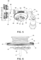
Figure 5 shows a first partial view of the gas tap ofFigure 1 . -
Figure 6 shows a second partial view of the gas tap ofFigure 1 . -
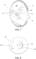
Figure 7 shows the actuator element of the gas tap ofFigure 1 . -
Figure 8 shows the regulating disc of the gas tap ofFigure 1 . -
Figure 9 shows the body of the gas tap ofFigure 1 . -
Figure 10 shows the worm screw of the gas tap ofFigure 1 . - A first aspect of the invention relates to a
gas tap 1 with asafety valve 20 for a gas cooking appliance. - The
gas tap 1 of the invention comprises abody 10 comprising agas inlet conduit 11 fluidically connected with thesafety valve 20, at least onegas outlet conduit housing 14 fluidically connected with thesafety valve 20 and with said at least oneoutlet conduit housing 14 comprises acontact surface 140 comprising at least oneoutlet hole outlet conduit gas tap 1 comprises between one and three outlet conduits. - Preferably the
safety valve 20 is a normally closed solenoid valve housed in asafety conduit 19 of thebody 10, saidsafety conduit 19 being connected with thegas inlet conduit 11. Saidsafety valve 20 comprises aplug 21, saidplug 21 being configured to be displaced between a closed position in which it is arranged on aseating 18 of thesafety conduit 19, preventing the gas flow, and a passage position in which theplug 21 is separated from theseating 18, allowing the gas flow from theinlet conduit 11 to thehousing 14 through a passage opening 180 connecting thesafety conduit 19 with thehousing 14 of thebody 10. In that sense, when theplug 21 is arranged in the closed position, thesafety valve 20 is considered to be closed, whereas when theplug 21 is arranged in the passage position, thesafety valve 20 is considered to be open. Thesafety valve 20 also comprises aspring 22 which causes theplug 21 to be in the closed position. The initial opening of thesafety valve 20 is performed by mechanically pushing theplug element 21, separating it from theseating 18, and preferably, during a brief predetermined period of time, thesafety valve 20 is electronically powered to keep thesafety valve 20 open. Once said period has passed, while the burner associated with thegas tap 1 is on, the corresponding thermocouple keeps the safety valve energized and, accordingly, theplug 21 in the passage position. - The
gas tap 1 also comprises a regulatingdisc 30 comprising at least one regulation opening 31a, 31b. The regulatingdisc 30 is arranged in thehousing 14 of thebody 10 over thecontact surface 140. The regulatingdisc 30 is configured to regulate, by means of rotating same, the incoming gas flow from thesafety valve 20 to said at least oneoutlet conduit disc 30 comprises a series ofregulation openings outlet conduit housing 14 and thecorresponding outlet conduit disc 30. Alternatively, the regulating disc may comprise a single regulation opening per outlet conduit. The regulation of the gas flow occurs when at least one regulation opening 31a, 31b and thecorresponding outlet hole - Furthermore, the
gas tap 1 comprises amotor 80, preferably a BLDC motor, comprising anoutput shaft 81. A stepper motor or any other low torque motor could also be used. - The
gas tap 1 also comprises a gear coupled to theshaft 81 of themotor 80 and configured to transmit the movement of themotor 80 to the regulatingdisc 30. - The
gas tap 1 comprises anactuator element 40 housed in thebody 10 and configured to open thesafety valve 20 by means of its rotation. Furthermore, theactuator element 40 is a wheel comprising a plurality ofteeth 41, theactuator element 40 being part of the gear. Preferably the plurality ofteeth 41 are arranged on at least part of the perimeter of theactuator element 40. - In that sense, the
actuator element 40 is an at least partially toothed wheel which, in addition to being part of the gear that transmits the rotation of theshaft 81 of themotor 80 to the regulatingdisc 30, is also configured to open thesafety valve 20 by means of its rotation. Theactuator element 40 thereby performs a dual function, and an actuation mechanism of thegas tap 1 with fewer parts, and which is therefore simpler and more compact, can be obtained. - In that sense, the
gas tap 1 of the invention is a motor-drivengas tap 1 which, by means of the rotation of themotor 80, can on one hand mechanically open thesafety valve 20, and on the other hand regulate the gas flow from theinlet conduit 11 to said at least oneoutlet conduit - Preferably the
motor 80 is arranged outside thehousing 14 of thebody 10, i.e., themotor 80 is arranged outside the area through which the gas circulates. The fact that themotor 80 is arranged outside thehousing 14, and therefore outside the gas circuit, prevents the gas tap from having to overcome testing required by law for gas taps in which there is electricity inside a housing through which the gas circulates. Furthermore, the arrangement of themotor 80 outside thehousing 14 of thebody 10 facilitates the tightness of thegas tap 1, given that in the event that the motor is inside the housing of the body, the cavity to be isolated would increase considerably, and furthermore a system would have to be designed to assure the isolation of the power cables and control of the motor. - Preferably the gear comprises a
worm screw 60, saidworm screw 60 being coupled to theshaft 81 of themotor 80, and saidworm screw 60 engaging with theteeth 41 of theactuator element 40. In that sense, therotation shaft 600 of theworm screw 60 is arranged perpendicular with respect to therotation shaft 402 of theactuator element 40. Preferably thebody 10 comprises an inlet hole which allows introducing theworm screw 60 inside thebody 10. Theworm screw 60 thereby comprises a first end arranged outside thebody 10, said first end being coupled to theshaft 81 of the motor, and the rest of theworm screw 60 being housed in thebody 10. Preferably thegas tap 1 comprises alip seal 56 arranged surrounding theworm screw 60 and supported against thebody 10 to seal the inlet hole and thus maintain the tightness of said inlet port. The tightness required is obtained with thelip seal 56, exercising a friction force on theworm screw 60 that is considerably less than force that would be exerted on said worm screw in the case of using an O-ring commonly used in motor-driven gas taps in which the motor is arranged outside the housing of the body. Taking into account that to obtain a cost-effective solution, it would be of interest to use amotor 80 with a low output torque, the fact that the friction force to be exerted by thelip seal 56 is small is a great advantage. - This type of gear known as a "worm gear" allows reducing the output speed of the
motor 80 by increasing the torque in the transmission. Amotor 80 with a low output torque can thereby be used, obtaining as a result of the type of gear the torque necessary in theactuator element 40 to cause the opening of thesafety valve 20. The motors with a low output torque are usually less expensive, so the use of this type of gear, also in addition to the dual function of theactuator element 40 which allows using fewer parts, makes thegas tap 1 of the invention a less expensive and simpler solution. Furthermore, this type of "worm screw-worm screw wheel" gear requires less space and achieves a greater reduction of speed-increase of output torque than in a gear with parallel shafts, such that the solution of the invention requires a lower number of parts in the transmission system, obtaining a less complex gas tap and facilitating the manufacture, assembly, and operation thereof. - In the worm gear type gears, radial stresses which can cause an imbalance in the movement of the rotor/stator of the motor coupled to the worm screw can be generated, causing the operation of the motor to be less efficient and being able to cause gas leaks in the
lip seal 56 located between thebody 10 and theworm screw 60. To that end, to minimize these possible radial displacements, preferably thegas tap 1 comprises at least onebushing worm screw 60, abushing 54 preferably being arranged after thelip seal 56. Said at least onebushing body 10, such that said at least onebushing worm screw 60 centered and prevents radial displacement thereof. More preferably, thegas tap 1 comprises afirst bushing 54 arranged in afirst part 61 of theworm screw 60 and asecond bushing 55 arranged in asecond part 62 of theworm screw 60, thetoothed part 63 of theworm screw 60 being arranged between thefirst part 61 and thesecond part 62. Additionally, thegas tap 1 may comprise anaxial stop 57 arranged in thebody 1, theworm screw 60 comprising anotch 65 cooperating with saidaxial stop 57 such that the possible axial displacements of theworm screw 60 are also minimized. - Preferably the
actuator element 40 comprises aprotrusion 42 configured to act indirectly on theplug element 21 of thesafety valve 20. Preferably theprotrusion 42 is arranged on the perimeter of theactuator element 40 and protrudes radially with respect to the perimeter of saidactuator element 40. - Preferably the
protrusion 42 can also be used to define a zero position of theregulating disc 30. To that end theprotrusion 42 can cooperate with an abutment wall of thebody 10 such that when said zero position is to be determined, theactuator element 40 is rotated in a search for zero direction, determining the zero position when theprotrusion 42 abuts with the abutment wall that prevents theactuator element 40 from being able to continue rotating in said direction. - Furthermore, preferably the
gas tap 1 comprises alever 70 arranged in thehousing 14 and rotationally fixed to thebody 10 by means of arotation shaft 73. Thelever 70 is configured to act on theplug element 21 of thesafety valve 20 when the rotation of theactuator element 40 causes theprotrusion 42 to act on thelever 70. Thelever 70 comprises a firstradial prolongation 71 configured to cooperate with theactuator element 40, and a secondradial prolongation 72 configured to cooperate with thesafety valve 20, therotation shaft 73 being arranged between bothradial prolongations radial prolongation 72 of thelever 70 is configured to act on theplug element 21 of thesafety valve 20, opening saidsafety valve 20 when theprotrusion 42 of theactuator element 40 pushes the firstradial prolongation 71 of thelever 70. In that sense, thelever 70 is configured to rotate between a standby position and a pushing position in which the secondradial prolongation 72 of thelever 70 goes through thepassage opening 180, thus separating theplug 21 from theseating 18, allowing the passage of gas from theinlet conduit 11 to thehousing 14 through thepassage opening 180. Thelever 70 amplifies the force transmitted by theactuator element 40 to theplug 21 such that its use as an intermediate element allows exerting the force needed to open thesafety valve 20 with a lower torque of theactuator element 40 than if saidactuator element 40 were to act directly on theplug 21. The use of thelever 70 thereby causes the torque required of themotor 80 to be able to open thesafety valve 20 to be lower. The at least oneregulation opening regulating disc 30 is arranged such that when theprotrusion 42 of theactuator element 40 is arranged in angular positions of the circular sector in which saidprotrusion 42 acts on thelever 70, said at least oneregulation opening outlet hole protrusion 42 acts on thelever 70, i.e., while theplug 21 of thesafety valve 20 is operated mechanically, such that in the event of a malfunction, if theactuator element 40 were to be blocked in an angular position in which theplug 21 is operated mechanically by thelever 70, it is ensured that there will be no gas leak. - Preferably the
regulating disc 30 is coupled to theactuator element 40 such that both parts rotate integrally, theactuator element 40 being what directly transmits the rotation to theregulating disc 30. To that end, preferably theactuator element 40 comprises acentral protrusion 43 and theregulating disc 30 comprises acentral hole 32 with a shape complementary to thecentral protrusion 43 of theactuator element 40, thecentral protrusion 43 being housed in thecentral hole 32 such that both parts rotate integrally. Alternatively, the regulating disc can be integrated in the actuator element itself. - Preferably the
body 10 comprises acentral hole 16 in which ashaft 51 is arranged, and thecentral protrusion 43 of the actuator element comprises acentral hole 430, theshaft 51 going through saidcentral hole 430 such that theactuator element 40 is configured to rotate with respect to saidshaft 51. - Preferably the
actuator element 40 comprises at least onepressure element 44 that protrudes with respect to thesurface 400 of theactuator element 40 which is arranged facing the regulatingdisc 30, said at least onepressure element 44 being configured to press the regulatingdisc 30 against thecontact surface 140. In that sense, theactuator element 40 also has the function of ensuring proper support of theregulating disc 30 over thecontact surface 140 of thehousing 14. - Preferably the
gas tap 1 comprises a sealinggasket 50 housed in thecontact surface 140 surrounding the at least oneoutlet hole disc 30 being arranged in a supported manner, pressing on said sealinggasket 50, the sealinggasket 50 ensuring the tightness between the regulatingdisc 30 and thecontact surface 140, such that it is assured that there will only be gas flow to the at least oneoutlet conduit regulation opening corresponding outlet hole - Preferably the
actuator element 40 is axially retained by means of aspring 52 that pushes theactuator element 40 at one of its ends, the other end of thespring 52 being supported in acover 15 attached to thebody 10 that closes thehousing 14 of thebody 10 in a leak-tight manner. Preferably thegas tap 1 comprises alower support part 58 manufactured in a low friction material, for example nylon, which is arranged between theactuator element 40 and thespring 52. Preferably thegas tap 1 also comprises anupper support part 58 which is arranged between thecover 15 and thespring 52. - Preferably the
gas tap 1 comprises asecond sealing gasket 53 arranged between thebody 10 and thecover 15. - A second aspect of the invention relates to a gas cooking appliance comprising at least one
gas tap 1 like the one described in the first aspect of the invention. -
Figures 1 to 9 show agas tap 1 according to a preferred embodiment of the invention. - In the preferred embodiment the
gas tap 1 comprises abody 10 comprising asafety conduit 19 in which asafety valve 20 is arranged, and agas inlet conduit 11 fluidically connected with saidsafety conduit 19. Thebody 10 also comprises twogas outlet conduits housing 14 fluidically connected with thesafety conduit 19 and with saidoutlet conduits housing 14 comprises acontact surface 140 comprising twooutlet holes outlet hole outlet conduit safety conduit 19 comprises aseating 18 comprising apassage opening 180 connecting thesafety conduit 19 with thehousing 14 of thebody 10. - In this preferred embodiment the
safety valve 20 is a normally closed solenoid valve. Thesafety valve 20 comprises aplug 21 configured to be displaced between a closed position in which theplug 21 is arranged on theseating 18 of thesafety conduit 19, preventing the gas flow, and a passage position in which theplug 21 is separated from theseating 18, allowing the gas flow from theinlet conduit 11 to thehousing 14 through apassage opening 180. Thesafety valve 20 comprises aspring 22 which causes theplug 21 to be in the closed position. The initial opening of thesafety valve 20 is performed by mechanically pushing theplug element 21, separating it from theseating 18 and during a brief predetermined period of time, thesafety valve 20 is electronically powered to keep thesafety valve 20 open. Once said period has passed, while the burner associated with the gas tap is on, the corresponding thermocouple keeps thesafety valve 20 energized and, accordingly, theplug 21 in the passage position. - The
gas tap 1 of the preferred embodiment also comprises aregulating disc 30 arranged in thehousing 14 of thebody 10 over thecontact surface 140. The regulatingdisc 30 is configured to regulate, by means of its rotation, the incoming gas flow from theinlet conduit 11, through thesafety valve 20, to theoutlet conduits disc 30 comprises a first series ofregulation openings 31a to regulate the gas flow from thehousing 14 of thebody 10 to thefirst outlet conduit 12 through thefirst outlet hole 120, and a second series ofregulation openings 31b to regulate the gas flow from thehousing 14 of thebody 10 to thesecond outlet conduit 13 through thesecond outlet hole 130. The openings of the series ofregulation openings regulation openings 31a being larger than the second series ofregulation openings 31b. To obtain the gas flow rate required in theoutlet conduits regulation openings regulating disc 30 overlap the outlet holes 120, 130. - The
gas tap 1 of the preferred embodiment also comprises aBLDC motor 80 arranged outside thehousing 14 of thebody 10. Themotor 80 comprises anoutput shaft 81. - The
gas tap 1 also comprises a gear coupled to theshaft 81 of themotor 80 and configured to transmit the movement of themotor 80 to theregulating disc 30. - The
gas tap 1 of the preferred embodiment also comprises anactuator element 40 housed in thebody 10 and configured to open thesafety valve 20 by means of its rotation. Theactuator element 40 is a wheel comprising a plurality ofteeth 41 arranged on part of the perimeter of theactuator element 40, theactuator element 40 being part of the gear. In that sense, theactuator element 40 is a partially toothed wheel which, in addition to being part of the gear that transmits the rotation of theshaft 81 of themotor 80 to theregulating disc 30, is also configured to open thesafety valve 20 by means of its rotation. - In the preferred embodiment the gear is a "worm gear". In that sense, the gear comprises a
worm screw 60 coupled to theshaft 81 of themotor 80, saidworm screw 60 engaging with theteeth 41 of theactuator element 40. - In this preferred embodiment the
body 10 comprises an inlet hole which allows introducing theworm screw 60 inside thebody 10. Theworm screw 60 thereby comprises a first end arranged outside thebody 10, said first end being coupled to theshaft 81 of the motor, and the rest of theworm screw 60 being housed in thebody 10, as observed in detail inFigure 3 . Thegas tap 1 comprises alip seal 56 arranged surrounding theworm screw 60 and supported against thebody 10 to seal the inlet hole and thus maintain the tightness of said inlet port. - Furthermore, as shown in detail in
Figure 3 , thegas tap 1 of the preferred embodiment comprises afirst bushing 54 arranged after thelip seal 56 and surrounding afirst part 61 of theworm screw 60, and asecond bushing 54 arranged surrounding asecond part 62 of theworm screw 60, thetoothed part 63 of theworm screw 60 being arranged between thefirst part 61 and thesecond part 62. Saidbushings body 10 such that saidbushings worm screw 60 centered and prevent radial displacement thereof. - In the preferred embodiment of the
gas tap 1, theactuator element 40 comprises aprotrusion 42 arranged on the perimeter of theactuator element 40 and protruding radially with respect to the perimeter of saidactuator element 40. Theprotrusion 42 is configured to act indirectly on theplug element 21 of thesafety valve 20. - Furthermore, the
gas tap 1 of the preferred embodiment comprises alever 70 arranged in thehousing 14 and rotationally fixed to thebody 10 by means of arotation shaft 73. Thelever 70 is configured to act on theplug element 21 of thesafety valve 20 when the rotation of theactuator element 40 causes theprotrusion 42 to act on thelever 70. Thelever 70 comprises a firstradial prolongation 71 configured to cooperate with theactuator element 40 and a secondradial prolongation 72 configured to cooperate with thesafety valve 20, therotation shaft 73 being arranged between bothradial prolongations radial prolongation 72 of thelever 70 is configured to act on theplug element 21 of thesafety valve 20, mechanically opening saidsafety valve 20 when theprotrusion 42 of theactuator element 40 pushes the firstradial prolongation 71 of thelever 70. - In this preferred embodiment the
lever 70 comprises a rectangular prism-shapedcentral part 74, the firstradial prolongation 71 extending perpendicularly from the proximity of one of the ends of thecentral part 74, and the secondradial prolongation 72 extending perpendicularly from the proximity of the opposite end of thecentral part 74. The firstradial prolongation 71 is arranged perpendicular to the secondradial prolongation 72. The first radial prolongation comprises a hole that therotation shaft 73 goes through. - As mentioned above, a worm gear allows reducing the speed by considerably increasing the output torque of the
motor 80. Furthermore, the use of thelever 70 as an intermediate element between theactuator element 40 and theplug 21 also increases the force exerted on saidplug 21. Therefore, as a result of the type of gear used and the use of thelever 70 as an intermediate element, amotor 80 with a low output torque, and therefore inexpensive, can be used to actuate thegas tap 1. - In the preferred embodiment of the
gas tap 1, the regulatingdisc 30 is coupled to theactuator element 40 such that both parts rotate integrally, theactuator element 40 being what directly transmits the rotation to theregulating disc 30. To that end, theactuator element 40 comprises acentral protrusion 43 and theregulating disc 30 comprises acentral hole 32 with a shape complementary to thecentral protrusion 43 of theactuator element 40, thecentral protrusion 43 being housed in thecentral hole 32 such that both parts rotate integrally. Thebody 10 comprises acentral hole 16 in which ashaft 51 is arranged, and thecentral protrusion 43 of the actuator element comprises acentral hole 430, saidcentral hole 430 going through theshaft 51 such that theactuator element 40 is configured to rotate with respect to saidshaft 51. - Furthermore, in the preferred embodiment of the
gas tap 1 theactuator element 40 comprises threepressure elements 44 which are prolonged perpendicularly from thesurface 400 of theactuator element 40 which is arranged facing the regulatingdisc 30, saidpressure elements 44 being configured to press the regulatingdisc 30 against thecontact surface 140. - The
gas tap 1 of the preferred embodiment comprises a sealinggasket 50 housed in thecontact surface 140 surrounding theoutlet hole disc 30 being arranged in a supported manner, pressing on said sealinggasket 50. - The
gas tap 1 of the preferred embodiment also comprises acover 15 attached to thebody 10 that closes thehousing 14 of thebody 10 in a leak-tight manner. As shown in detail inFigure 4 , theactuator element 40 is axially retained by means of aspring 52 that pushes theactuator element 40 at one of its ends, the other end of thespring 52 being supported in thecover 15. Thegas tap 1 comprises alower support part 58 manufactured in a low friction material, for example nylon, which is arranged between theactuator element 40 and thespring 52, and anupper support part 58 which is arranged between thecover 15 and thespring 52. - The
gas tap 1 of the preferred embodiment comprises asecond sealing gasket 53 arranged between thebody 10 and thecover 15.
Claims (15)
- Gas tap with a safety valve (20) for a gas cooking appliance, comprising- a body (10) comprising∘ a gas inlet conduit (11) fluidically connected with the safety valve (20),∘ at least one gas outlet conduit (12, 13), and∘ a housing (14) fluidically connected with the safety valve (20) and with said at least one outlet conduit (12, 13), the housing (14) comprising a contact surface (140) comprising at least one outlet hole (120, 130) fluidically connected with said at least one outlet conduit (12, 13),- a regulating disc (30) comprising at least one regulation opening and arranged in the housing (14) of the body (10) over the contact surface (140), the regulating disc (30) being configured to regulate, by means of its rotation, the incoming gas flow from the safety valve (20) to said at least one outlet conduit (12, 13),- an actuator element (40) housed in the body (10) and configured to open the safety valve (20) by means of its rotation,- a motor (80) comprising an output shaft (81), and- a gear coupled to the shaft (81) of the motor (80) and configured to transmit the movement of the motor (80) to the regulating disc (30),characterized in that
the actuator element (40) is a wheel comprising a plurality of teeth (41), the actuator element (40) being part of the gear. - The gas tap according to claim 1, wherein the motor (80) is arranged outside the housing (14) of the body (10).
- The gas tap according to claim 1 or 2, wherein the motor (80) is a BLDC motor.
- The gas tap according to any of claims 1 to 3, wherein the gear comprises a worm screw (60), said worm screw (60) being coupled to the shaft (81) of the motor (80), and said worm screw (60) engaging with the teeth (41) of the actuator element (40).
- The gas tap according to claim 4, comprising at least one bushing (54, 55) surrounding a part of the worm screw (60), said at least one bushing being housed in a retention housing for retaining the body (10) such that said at least one bushing (54, 55) keeps the worm screw (60) centered and prevents radial displacement thereof.
- The gas tap according to claim 5, comprising a first bushing (54) arranged in a first part (61) of the worm screw (60) and a second bushing (55) arranged in a second part (62) of the worm screw (60), the toothed part (63) of the worm screw (60) being arranged between the first part (61) and the second part (62).
- The gas tap according to any of claims 1 to 6, wherein the actuator element (40) comprises a protrusion (42) configured to act indirectly on a plug element (21) of the safety valve (20).
- The gas tap according to claim 7, comprising a lever (70) arranged in the housing (14) and rotationally fixed to the body (10), a second radial prolongation (72) of the lever (70) being configured to act on the plug element (21) of the safety valve (20), opening said safety valve (20) when the protrusion (42) of the actuator element (40) pushes a first radial prolongation (71) of the lever (70).
- The gas tap according to any of claims 1 to 8, wherein the regulating disc (30) is coupled to the actuator element (40) such that both parts rotate integrally.
- The gas tap according to claim 9, wherein the actuator element (40) comprises a central protrusion (43) and the regulating disc (30) comprises a central hole (32) with a shape complementary to the central protrusion (43) of the actuator element (40), the central protrusion (43) being housed in the central hole (32) such that both parts rotate integrally.
- The gas tap according to claim 9 or 10, wherein the actuator element (40) comprises at least one pressure element (44) that protrudes with respect to the surface (400) of the actuator element (40) which is arranged facing to the regulating disc (30), said at least one pressure element (44) being configured to press the regulating disc (30) against the contact surface (140).
- The gas tap according to any of claims 1 to 11, comprising a sealing gasket (50) housed in the contact surface (140) surrounding the at least one outlet hole (120, 130), the regulating disc (30) being arranged in a supported manner, pressing on said sealing gasket (50).
- The gas tap according to any of claims 1 to 8, wherein the regulating disc (30) is integrated in the actuator element (40) itself.
- The gas tap according to any of claims 1 to 13, wherein the actuator element (40) is axially retained by means of a spring (52) that pushes the actuator element (40) at one of its ends, the other end of the spring (52) being supported in a cover (15) attached to the body (10) that closes the housing (14) of the body (10) in a leak-tight manner.
- A gas cooking appliance comprising at least one gas tap (1) according to any of claims 1 to 14.
Priority Applications (5)
| Application Number | Priority Date | Filing Date | Title |
|---|---|---|---|
| PL23382761.7T PL4495482T3 (en) | 2023-07-21 | 2023-07-21 | Gas tap with safety valve for a gas cooking appliance |
| EP23382761.7A EP4495482B1 (en) | 2023-07-21 | 2023-07-21 | Gas tap with safety valve for a gas cooking appliance |
| ES23382761T ES3068489T3 (en) | 2023-07-21 | 2023-07-21 | |
| CN202410965502.1A CN119333608A (en) | 2023-07-21 | 2024-07-18 | Gas cock with safety valve for gas cooking appliances |
| US18/778,238 US20250027648A1 (en) | 2023-07-21 | 2024-07-19 | Gas tap with safety valve for a gas cooking appliance |
Applications Claiming Priority (1)
| Application Number | Priority Date | Filing Date | Title |
|---|---|---|---|
| EP23382761.7A EP4495482B1 (en) | 2023-07-21 | 2023-07-21 | Gas tap with safety valve for a gas cooking appliance |
Publications (2)
| Publication Number | Publication Date |
|---|---|
| EP4495482A1 true EP4495482A1 (en) | 2025-01-22 |
| EP4495482B1 EP4495482B1 (en) | 2026-01-28 |
Family
ID=87863170
Family Applications (1)
| Application Number | Title | Priority Date | Filing Date |
|---|---|---|---|
| EP23382761.7A Active EP4495482B1 (en) | 2023-07-21 | 2023-07-21 | Gas tap with safety valve for a gas cooking appliance |
Country Status (5)
| Country | Link |
|---|---|
| US (1) | US20250027648A1 (en) |
| EP (1) | EP4495482B1 (en) |
| CN (1) | CN119333608A (en) |
| ES (1) | ES3068489T3 (en) |
| PL (1) | PL4495482T3 (en) |
Citations (4)
| Publication number | Priority date | Publication date | Assignee | Title |
|---|---|---|---|---|
| JP3819307B2 (en) * | 2002-03-04 | 2006-09-06 | リンナイ株式会社 | Gas flow control device |
| EP2299156A2 (en) * | 2009-09-18 | 2011-03-23 | E.G.O. ELEKTRO-GERÄTEBAU GmbH | Rotor blade, rotor blade valve and valve device |
| EP3211309A1 (en) * | 2016-02-24 | 2017-08-30 | Copreci, S.Coop. | Regulating valve for a gas cooking appliance and gas cooking appliance incorporating said regulating valve |
| EP3828467A1 (en) * | 2019-11-29 | 2021-06-02 | Copreci, S.Coop. | Regulating valve for a gas cooking appliance, and gas cooking appliance incorporating said regulating valve |
-
2023
- 2023-07-21 PL PL23382761.7T patent/PL4495482T3/en unknown
- 2023-07-21 ES ES23382761T patent/ES3068489T3/es active Active
- 2023-07-21 EP EP23382761.7A patent/EP4495482B1/en active Active
-
2024
- 2024-07-18 CN CN202410965502.1A patent/CN119333608A/en active Pending
- 2024-07-19 US US18/778,238 patent/US20250027648A1/en active Pending
Patent Citations (4)
| Publication number | Priority date | Publication date | Assignee | Title |
|---|---|---|---|---|
| JP3819307B2 (en) * | 2002-03-04 | 2006-09-06 | リンナイ株式会社 | Gas flow control device |
| EP2299156A2 (en) * | 2009-09-18 | 2011-03-23 | E.G.O. ELEKTRO-GERÄTEBAU GmbH | Rotor blade, rotor blade valve and valve device |
| EP3211309A1 (en) * | 2016-02-24 | 2017-08-30 | Copreci, S.Coop. | Regulating valve for a gas cooking appliance and gas cooking appliance incorporating said regulating valve |
| EP3828467A1 (en) * | 2019-11-29 | 2021-06-02 | Copreci, S.Coop. | Regulating valve for a gas cooking appliance, and gas cooking appliance incorporating said regulating valve |
Also Published As
| Publication number | Publication date |
|---|---|
| EP4495482B1 (en) | 2026-01-28 |
| US20250027648A1 (en) | 2025-01-23 |
| ES3068489T3 (en) | 2026-06-01 |
| PL4495482T3 (en) | 2026-06-08 |
| CN119333608A (en) | 2025-01-21 |
Similar Documents
| Publication | Publication Date | Title |
|---|---|---|
| JP7057243B2 (en) | Valve drive | |
| US9441750B2 (en) | Valve cartridge | |
| CN110418894B (en) | Pump unit | |
| US10823175B2 (en) | Pump assembly and hydraulic system | |
| CN110418893B (en) | Centrifugal pump unit | |
| EP4345346B1 (en) | Proportional valve | |
| US6918408B2 (en) | Valve driving device | |
| JP7519265B2 (en) | Motor-operated valve and refrigeration cycle system | |
| CN108071839A (en) | Motor-driven valve and the refrigerating circulation system for having used the motor-driven valve | |
| US2988108A (en) | Multi-way valve | |
| EP3546830A1 (en) | Gas cock with a safety valve for a gas cooking appliance, and gas cooking appliance incorporating said gas cock | |
| US3248080A (en) | Motor-spring operated valve | |
| EP4495482B1 (en) | Gas tap with safety valve for a gas cooking appliance | |
| CN114321445B (en) | Tap valve device | |
| EP3521701A1 (en) | Gas cock with a safety valve for a gas cooking appliance, and gas cooking appliance incorporating said gas cock | |
| CA2451546A1 (en) | A valve and a gas burner | |
| CN110220008B (en) | Electric valve | |
| EP3828467B1 (en) | Regulating valve for a gas cooking appliance, and gas cooking appliance incorporating said regulating valve | |
| EP4143441B1 (en) | Centrifugal pump assembly | |
| CN109630715B (en) | Faucet device | |
| US20200124203A1 (en) | Gas valve with emergency shutoff and mechanical timer | |
| JP2018084285A (en) | Mixing valve unit | |
| JP2020115043A (en) | Flow channel change-over valve | |
| EP3193049B1 (en) | Valve | |
| US20210156396A1 (en) | Centrifugal pump assembly |
Legal Events
| Date | Code | Title | Description |
|---|---|---|---|
| PUAI | Public reference made under article 153(3) epc to a published international application that has entered the european phase |
Free format text: ORIGINAL CODE: 0009012 |
|
| STAA | Information on the status of an ep patent application or granted ep patent |
Free format text: STATUS: THE APPLICATION HAS BEEN PUBLISHED |
|
| AK | Designated contracting states |
Kind code of ref document: A1 Designated state(s): AL AT BE BG CH CY CZ DE DK EE ES FI FR GB GR HR HU IE IS IT LI LT LU LV MC ME MK MT NL NO PL PT RO RS SE SI SK SM TR |
|
| STAA | Information on the status of an ep patent application or granted ep patent |
Free format text: STATUS: REQUEST FOR EXAMINATION WAS MADE |
|
| 17P | Request for examination filed |
Effective date: 20250722 |
|
| GRAP | Despatch of communication of intention to grant a patent |
Free format text: ORIGINAL CODE: EPIDOSNIGR1 |
|
| STAA | Information on the status of an ep patent application or granted ep patent |
Free format text: STATUS: GRANT OF PATENT IS INTENDED |
|
| INTG | Intention to grant announced |
Effective date: 20250902 |
|
| RIN1 | Information on inventor provided before grant (corrected) |
Inventor name: ARRIOLA-BENGOA UNZUETA, IMANOL Inventor name: PENAGARICANO BADIOLA, INIGO |
|
| GRAS | Grant fee paid |
Free format text: ORIGINAL CODE: EPIDOSNIGR3 |
|
| GRAA | (expected) grant |
Free format text: ORIGINAL CODE: 0009210 |
|
| STAA | Information on the status of an ep patent application or granted ep patent |
Free format text: STATUS: THE PATENT HAS BEEN GRANTED |
|
| AK | Designated contracting states |
Kind code of ref document: B1 Designated state(s): AL AT BE BG CH CY CZ DE DK EE ES FI FR GB GR HR HU IE IS IT LI LT LU LV MC ME MK MT NL NO PL PT RO RS SE SI SK SM TR |
|
| REG | Reference to a national code |
Ref country code: CH Ref legal event code: F10 Free format text: ST27 STATUS EVENT CODE: U-0-0-F10-F00 (AS PROVIDED BY THE NATIONAL OFFICE) Effective date: 20260128 Ref country code: GB Ref legal event code: FG4D |
|
| REG | Reference to a national code |
Ref country code: DE Ref legal event code: R096 Ref document number: 602023011296 Country of ref document: DE |
|
| REG | Reference to a national code |
Ref country code: IE Ref legal event code: FG4D |
|
| REG | Reference to a national code |
Ref country code: ES Ref legal event code: FG2A Ref document number: 3068489 Country of ref document: ES Kind code of ref document: T3 Effective date: 20260601 |
|
| REG | Reference to a national code |
Ref country code: NL Ref legal event code: MP Effective date: 20260128 |
|
| PG25 | Lapsed in a contracting state [announced via postgrant information from national office to epo] |
Ref country code: NL Free format text: LAPSE BECAUSE OF FAILURE TO SUBMIT A TRANSLATION OF THE DESCRIPTION OR TO PAY THE FEE WITHIN THE PRESCRIBED TIME-LIMIT Effective date: 20260128 |
|
| REG | Reference to a national code |
Ref country code: AT Ref legal event code: MK05 Ref document number: 1881683 Country of ref document: AT Kind code of ref document: T Effective date: 20260128 |
|
| PG25 | Lapsed in a contracting state [announced via postgrant information from national office to epo] |
Ref country code: RS Free format text: LAPSE BECAUSE OF FAILURE TO SUBMIT A TRANSLATION OF THE DESCRIPTION OR TO PAY THE FEE WITHIN THE PRESCRIBED TIME-LIMIT Effective date: 20260428 |
|
| PG25 | Lapsed in a contracting state [announced via postgrant information from national office to epo] |
Ref country code: GR Free format text: LAPSE BECAUSE OF FAILURE TO SUBMIT A TRANSLATION OF THE DESCRIPTION OR TO PAY THE FEE WITHIN THE PRESCRIBED TIME-LIMIT Effective date: 20260429 |
|
| REG | Reference to a national code |
Ref country code: LT Ref legal event code: MG9D |
|
| PG25 | Lapsed in a contracting state [announced via postgrant information from national office to epo] |
Ref country code: LT Free format text: LAPSE BECAUSE OF FAILURE TO SUBMIT A TRANSLATION OF THE DESCRIPTION OR TO PAY THE FEE WITHIN THE PRESCRIBED TIME-LIMIT Effective date: 20260128 |
|
| PG25 | Lapsed in a contracting state [announced via postgrant information from national office to epo] |
Ref country code: NO Free format text: LAPSE BECAUSE OF FAILURE TO SUBMIT A TRANSLATION OF THE DESCRIPTION OR TO PAY THE FEE WITHIN THE PRESCRIBED TIME-LIMIT Effective date: 20260428 |
|
| PG25 | Lapsed in a contracting state [announced via postgrant information from national office to epo] |
Ref country code: SE Free format text: LAPSE BECAUSE OF FAILURE TO SUBMIT A TRANSLATION OF THE DESCRIPTION OR TO PAY THE FEE WITHIN THE PRESCRIBED TIME-LIMIT Effective date: 20260128 Ref country code: FI Free format text: LAPSE BECAUSE OF FAILURE TO SUBMIT A TRANSLATION OF THE DESCRIPTION OR TO PAY THE FEE WITHIN THE PRESCRIBED TIME-LIMIT Effective date: 20260128 Ref country code: AT Free format text: LAPSE BECAUSE OF FAILURE TO SUBMIT A TRANSLATION OF THE DESCRIPTION OR TO PAY THE FEE WITHIN THE PRESCRIBED TIME-LIMIT Effective date: 20260128 |
|
| PG25 | Lapsed in a contracting state [announced via postgrant information from national office to epo] |
Ref country code: HR Free format text: LAPSE BECAUSE OF FAILURE TO SUBMIT A TRANSLATION OF THE DESCRIPTION OR TO PAY THE FEE WITHIN THE PRESCRIBED TIME-LIMIT Effective date: 20260128 |
|
| PG25 | Lapsed in a contracting state [announced via postgrant information from national office to epo] |
Ref country code: IS Free format text: LAPSE BECAUSE OF FAILURE TO SUBMIT A TRANSLATION OF THE DESCRIPTION OR TO PAY THE FEE WITHIN THE PRESCRIBED TIME-LIMIT Effective date: 20260528 Ref country code: PT Free format text: LAPSE BECAUSE OF FAILURE TO SUBMIT A TRANSLATION OF THE DESCRIPTION OR TO PAY THE FEE WITHIN THE PRESCRIBED TIME-LIMIT Effective date: 20260528 |
|
| PG25 | Lapsed in a contracting state [announced via postgrant information from national office to epo] |
Ref country code: LV Free format text: LAPSE BECAUSE OF FAILURE TO SUBMIT A TRANSLATION OF THE DESCRIPTION OR TO PAY THE FEE WITHIN THE PRESCRIBED TIME-LIMIT Effective date: 20260128 |
|
| PG25 | Lapsed in a contracting state [announced via postgrant information from national office to epo] |
Ref country code: BG Free format text: LAPSE BECAUSE OF FAILURE TO SUBMIT A TRANSLATION OF THE DESCRIPTION OR TO PAY THE FEE WITHIN THE PRESCRIBED TIME-LIMIT Effective date: 20260128 |