EP4495445A1 - Cage for rolling bearing, rolling bearing, and method of designing cage for rolling bearing - Google Patents
Cage for rolling bearing, rolling bearing, and method of designing cage for rolling bearing Download PDFInfo
- Publication number
- EP4495445A1 EP4495445A1 EP23770143.8A EP23770143A EP4495445A1 EP 4495445 A1 EP4495445 A1 EP 4495445A1 EP 23770143 A EP23770143 A EP 23770143A EP 4495445 A1 EP4495445 A1 EP 4495445A1
- Authority
- EP
- European Patent Office
- Prior art keywords
- cage
- rolling bearing
- wedge
- pockets
- Prior art date
- Legal status (The legal status is an assumption and is not a legal conclusion. Google has not performed a legal analysis and makes no representation as to the accuracy of the status listed.)
- Granted
Links
Images




Classifications
-
- F—MECHANICAL ENGINEERING; LIGHTING; HEATING; WEAPONS; BLASTING
- F16—ENGINEERING ELEMENTS AND UNITS; GENERAL MEASURES FOR PRODUCING AND MAINTAINING EFFECTIVE FUNCTIONING OF MACHINES OR INSTALLATIONS; THERMAL INSULATION IN GENERAL
- F16C—SHAFTS; FLEXIBLE SHAFTS; ELEMENTS OR CRANKSHAFT MECHANISMS; ROTARY BODIES OTHER THAN GEARING ELEMENTS; BEARINGS
- F16C33/00—Parts of bearings; Special methods for making bearings or parts thereof
- F16C33/30—Parts of ball or roller bearings
- F16C33/46—Cages for rollers or needles
- F16C33/467—Details of individual pockets, e.g. shape or roller retaining means
- F16C33/4676—Details of individual pockets, e.g. shape or roller retaining means of the stays separating adjacent cage pockets, e.g. guide means for the bearing-surface of the rollers
-
- F—MECHANICAL ENGINEERING; LIGHTING; HEATING; WEAPONS; BLASTING
- F16—ENGINEERING ELEMENTS AND UNITS; GENERAL MEASURES FOR PRODUCING AND MAINTAINING EFFECTIVE FUNCTIONING OF MACHINES OR INSTALLATIONS; THERMAL INSULATION IN GENERAL
- F16C—SHAFTS; FLEXIBLE SHAFTS; ELEMENTS OR CRANKSHAFT MECHANISMS; ROTARY BODIES OTHER THAN GEARING ELEMENTS; BEARINGS
- F16C33/00—Parts of bearings; Special methods for making bearings or parts thereof
- F16C33/30—Parts of ball or roller bearings
- F16C33/66—Special parts or details in view of lubrication
- F16C33/6637—Special parts or details in view of lubrication with liquid lubricant
- F16C33/6681—Details of distribution or circulation inside the bearing, e.g. grooves on the cage or passages in the rolling elements
-
- F—MECHANICAL ENGINEERING; LIGHTING; HEATING; WEAPONS; BLASTING
- F16—ENGINEERING ELEMENTS AND UNITS; GENERAL MEASURES FOR PRODUCING AND MAINTAINING EFFECTIVE FUNCTIONING OF MACHINES OR INSTALLATIONS; THERMAL INSULATION IN GENERAL
- F16C—SHAFTS; FLEXIBLE SHAFTS; ELEMENTS OR CRANKSHAFT MECHANISMS; ROTARY BODIES OTHER THAN GEARING ELEMENTS; BEARINGS
- F16C19/00—Bearings with rolling contact, for exclusively rotary movement
- F16C19/22—Bearings with rolling contact, for exclusively rotary movement with bearing rollers essentially of the same size in one or more circular rows, e.g. needle bearings
- F16C19/24—Bearings with rolling contact, for exclusively rotary movement with bearing rollers essentially of the same size in one or more circular rows, e.g. needle bearings for radial load mainly
- F16C19/26—Bearings with rolling contact, for exclusively rotary movement with bearing rollers essentially of the same size in one or more circular rows, e.g. needle bearings for radial load mainly with a single row of rollers
-
- F—MECHANICAL ENGINEERING; LIGHTING; HEATING; WEAPONS; BLASTING
- F16—ENGINEERING ELEMENTS AND UNITS; GENERAL MEASURES FOR PRODUCING AND MAINTAINING EFFECTIVE FUNCTIONING OF MACHINES OR INSTALLATIONS; THERMAL INSULATION IN GENERAL
- F16C—SHAFTS; FLEXIBLE SHAFTS; ELEMENTS OR CRANKSHAFT MECHANISMS; ROTARY BODIES OTHER THAN GEARING ELEMENTS; BEARINGS
- F16C2208/00—Plastics; Synthetic resins, e.g. rubbers
- F16C2208/02—Plastics; Synthetic resins, e.g. rubbers comprising fillers, fibres
-
- F—MECHANICAL ENGINEERING; LIGHTING; HEATING; WEAPONS; BLASTING
- F16—ENGINEERING ELEMENTS AND UNITS; GENERAL MEASURES FOR PRODUCING AND MAINTAINING EFFECTIVE FUNCTIONING OF MACHINES OR INSTALLATIONS; THERMAL INSULATION IN GENERAL
- F16C—SHAFTS; FLEXIBLE SHAFTS; ELEMENTS OR CRANKSHAFT MECHANISMS; ROTARY BODIES OTHER THAN GEARING ELEMENTS; BEARINGS
- F16C2220/00—Shaping
- F16C2220/02—Shaping by casting
- F16C2220/04—Shaping by casting by injection-moulding
-
- F—MECHANICAL ENGINEERING; LIGHTING; HEATING; WEAPONS; BLASTING
- F16—ENGINEERING ELEMENTS AND UNITS; GENERAL MEASURES FOR PRODUCING AND MAINTAINING EFFECTIVE FUNCTIONING OF MACHINES OR INSTALLATIONS; THERMAL INSULATION IN GENERAL
- F16C—SHAFTS; FLEXIBLE SHAFTS; ELEMENTS OR CRANKSHAFT MECHANISMS; ROTARY BODIES OTHER THAN GEARING ELEMENTS; BEARINGS
- F16C2240/00—Specified values or numerical ranges of parameters; Relations between them
- F16C2240/30—Angles, e.g. inclinations
-
- F—MECHANICAL ENGINEERING; LIGHTING; HEATING; WEAPONS; BLASTING
- F16—ENGINEERING ELEMENTS AND UNITS; GENERAL MEASURES FOR PRODUCING AND MAINTAINING EFFECTIVE FUNCTIONING OF MACHINES OR INSTALLATIONS; THERMAL INSULATION IN GENERAL
- F16C—SHAFTS; FLEXIBLE SHAFTS; ELEMENTS OR CRANKSHAFT MECHANISMS; ROTARY BODIES OTHER THAN GEARING ELEMENTS; BEARINGS
- F16C2300/00—Application independent of particular apparatuses
- F16C2300/20—Application independent of particular apparatuses related to type of movement
- F16C2300/22—High-speed rotation
-
- F—MECHANICAL ENGINEERING; LIGHTING; HEATING; WEAPONS; BLASTING
- F16—ENGINEERING ELEMENTS AND UNITS; GENERAL MEASURES FOR PRODUCING AND MAINTAINING EFFECTIVE FUNCTIONING OF MACHINES OR INSTALLATIONS; THERMAL INSULATION IN GENERAL
- F16C—SHAFTS; FLEXIBLE SHAFTS; ELEMENTS OR CRANKSHAFT MECHANISMS; ROTARY BODIES OTHER THAN GEARING ELEMENTS; BEARINGS
- F16C2322/00—Apparatus used in shaping articles
- F16C2322/39—General buildup of machine tools, e.g. spindles, slides, actuators
Definitions
- the present invention relates to a rolling bearing cage, a rolling bearing, and a method of designing a rolling bearing cage.
- a main shaft of a machine tool thermally expands in an axial direction due to heat generated by a bearing and a motor during operation, and a front bearing and a rear bearing are stretched, resulting in excessive axial load and risk of bearing damage.
- a cylindrical roller bearing having a sliding function may be used as the rear bearing.
- the main shaft of the machine tool is often operated at high-speed rotation, and the cylindrical roller bearing may develop a negative radial clearance due to an influence of centrifugal force or heat during operation.
- the cage includes a bearing ring guide cage and a rolling element guide cage according to a guide method.
- a rolling element guide cage 14B is restricted in movement in a radial direction by a rolling element 13.
- the rolling element 13 comes into contact with a tip end portion 20a of an inner holding portion 20 provided on an inner diameter side of a column portion 17 or a tip end portion 22a of an outer holding portion 22 provided on an outer diameter side, thereby restricting movement of the cage 14B in the radial direction.
- the rolling element 13 may come into contact with a holding portion (the inner holding portion 20 and the outer holding portion 22) and engage with the holding portion in a wedge shape in a specific single pocket 15, and smooth rotation may be prevented.
- a wedge in the single pocket 15 is designed such that wedge angles ⁇ p and ⁇ q are as large as possible, and even when the cage 14B moves in the radial direction, it is difficult for the rolling element 13 to engage with the holding portions 20 and 22.
- the wedge angles ⁇ p and ⁇ q are angles formed by a tangent T to an outer circumference of the rolling element 13 at a contact point between the rolling element 13 and the holding portion and a line CL connecting a center of the rolling element 13 and a center of the cage 14B.
- Patent Literature 1 discloses a cylindrical roller bearing including a cage of a rolling element guide type that prevents a wedge action of a column portion of the cage in the cylindrical roller bearing, by setting an angle formed by a line segment connecting a point where the column portion of the cage comes into contact with a cylindrical roller and a roller center and a line connecting the roller center and a cage center and extending in a radial direction, in a range of 60° or more and 72° or less.
- Patent Literature 2 discloses a rolling bearing cage in which an angle formed by an imaginary line passing through a contact point between a rolling element and a tapered surface and a center of the rolling element and an imaginary perpendicular plane passing through the center of the rolling element and perpendicular to a radial direction is set to be larger than a friction angle set based on a friction coefficient at the contact point between the rolling element and the tapered surface, and in a specific single rolling element and a pocket in which the rolling element is accommodated, it is possible to avoid edge contact between the rolling element and a pocket surface and engagement in a wedge shape.
- the wedge action between the cage and the rolling element may occur not only in a single pocket but also between two pockets having different phases due to movement of the cage in the radial direction, lead or lag of the rolling element (roller), and the like.
- Patent Literature 1 and Patent Literature 2 both deal with a problem of wedging in a single pocket, and do not refer to engagement of a roller due to a wedge action generated between two different pockets (not only adjacent pockets but also separate pockets) due to lead, lag, and the like of a rolling element (roller).
- the present invention has been made in view of the above-described problem, and an object of the present invention is to provide a rolling bearing cage, a rolling bearing, and a method of designing a rolling bearing cage, which are capable of preventing damage to a column portion of the cage due to a wedge action formed between two pockets having different phases, and also preventing damage to the column portion of the cage due to a wedge action formed in a single pocket.
- the rolling bearing cage, the rolling bearing, and the method of designing a rolling bearing cage of the present invention it is possible to prevent damage to a column portion of the cage due to a wedge action formed between two pockets having different phases, and it is also possible to prevent damage to the column portion of the cage due to a wedge action formed in a single pocket.
- a rolling bearing 10 includes an outer ring 11 having an outer ring raceway 11a formed on an inner circumferential surface thereof, an inner ring 12 having an inner ring raceway 12a formed on an outer circumferential surface thereof, cylindrical rollers 13 which are a plurality of rolling elements disposed between the outer ring raceway 11a and the inner ring raceway 12a, and a cage 14 having a plurality of pockets 15 for holding the plurality of cylindrical rollers 13 in a rollable manner.
- the inner ring 12 includes annular flange portions 12b protruding to an outer diameter side on both sides in an axial direction, and restricts movement of the cylindrical roller 13 in the axial direction.
- the outer ring 11, the inner ring 12, and the cylindrical roller 13 are made of iron, and the cage 14 is made of synthetic resin.
- Examples of the synthetic resin material used for the cage 14 include phenol resin containing a basic material.
- phenol resin containing a basic material paper, cotton fabric, asbestos fabric, glass fiber fabric and nylon fabric may be used for a laminated plate, and wood powder, cotton, pulp, asbestos, mica, glass fiber, or the like may be used for a molded product.
- Resin such as polyamide, polyacetal, polyether ether ketone, polyimide, or polyphenylene sulfide may be used, and a reinforcing material such as glass fiber, carbon fiber, or aramid fiber may be added as necessary.
- the cage 14 may be made of a copper alloy or iron plated with silver or the like.
- the cage 14 includes a pair of annular portions 16 formed on both sides in the axial direction, and a plurality of column portions 17 connecting the pair of annular portions 16 in the axial direction and formed at predetermined intervals in a circumferential direction.
- the pocket 15 is formed between the pair of annular portions 16 and adjacent column portions 17.
- the cage 14 is an internally held rolling element guide cage, and side surfaces of the column portions 17 opposed to each other in the circumferential direction have an inner holding portion 20 that is curved toward an inner diameter side of the pocket 15, and outer diameter sides from the inner holding portion 20 are planes 21 parallel to each other.
- the inner holding portion 20 may be formed over the entire pocket 15 in the axial direction, or may be divided in the axial direction and formed symmetrically.
- the cage 14 and the cylindrical roller 13 move relative to each other in a radial direction, the cage 14 does not come into contact with the outer ring 11 and the inner ring 12, and a tip end portions 20a of the inner holding portion 20 come into contact with the cylindrical roller 13, thereby restricting movement of the cage 14 in the radial direction. That is, when the cage 14 is moved upward from a state shown in the drawing, the inner holding portion 20 abuts against the cylindrical roller 13 and the movement is restricted. When the cage 14 is moved downward, the inner holding portion 20 on an opposite side by 180° comes into contact with the cylindrical roller 13 and the movement is restricted.
- the inner holding portion 20 When a cross section of the cage 14 is viewed in the axial direction, the inner holding portion 20 is formed with a radius of curvature R 1 larger than a radius r of the cylindrical roller 13, and the inner holding portions 20 opposed to each other in the circumferential direction form a Gothic arch shape by extending and intersecting arcs of each other.
- a wedge W in (n is a positive integer starting from 1) is formed.
- an angle formed by a tangent T to the tip end portions 20a forms a wedge angle 2 ⁇ n (n is a positive integer starting from 1) between the plurality of pockets 15.
- the wedge angle 2 ⁇ n is formed by the tangent T to the tip end portions 20a of the inner holding portions 20 on the sides where the pocket surfaces are in a back-to-back relationship of a pair of inner holding portions 20 in a predetermined pocket 15 (reference pocket 15A) and a pair of inner holding portions 20 in each pocket 15 n (n: 1, 2, ..., z-1 (z is the total number of pockets)) spaced apart in the circumferential direction with respect to the predetermined pocket 15A.
- a design is made such that a positive minimum value 2 ⁇ min of wedge angles 2 ⁇ n of the plurality of wedges W in satisfies ⁇ min > tan -1 ( ⁇ ).
- ⁇ is a friction coefficient between the cage 14 and the cylindrical roller 13.
- the wedge angle 2 ⁇ n formed between different pockets 15 is different for each combination of pockets 15, and in the cage 14 having the total number of pockets Z, the wedge angle 2 ⁇ n formed between the reference pocket 15A and an n-th pocket 15 n in a circumferential direction counterclockwise from the reference pocket 15A is represented by the following formula (1) using an angle ⁇ 0 formed by a line L1 connecting a pocket diameter center (center of curvature of the inner holding portion 20) O1 and the tip end portion 20a of the inner holding portion 20 and a line L2 perpendicular to a symmetry line L3 of the pockets 15.
- Fig. 2 shows a state in which the cylindrical rollers 13 are arranged at equal intervals in the circumferential direction and the cage 14 is located at the neutral position.
- the neutral position refers to a case where a rotation center of the rolling bearing 10 and the center C of the cage 14 coincide with each other and the center O2 of the cylindrical roller 13 is on the symmetry line L3 of the pockets 15.
- the wedge angle 2 ⁇ n formed between different pockets 15 varies for each pocket 15 at a pitch of -360/Z, and the wedge angle 2 ⁇ min , which always has a positive minimum value, is present therein.
- a negative wedge angle 2 ⁇ n does not cause a problem since the negative wedge angle 2 ⁇ n is a direction in which a wedge is removed.
- a force generated by the wedge W in is reduced by designing the wedge angle 2 ⁇ n such that the positive minimum value 2 ⁇ min is as large as possible.
- F is a force for driving a wedge
- 2 ⁇ is a wedge angle
- N is a reaction force from an object into which the wedge is driven
- the reaction force of N is a force that the object receives from the wedge.
- a material for the cage 14 is resin
- a material for the cylindrical roller 13 is iron
- the friction coefficient ⁇ between the resin and the iron is 0.2
- the force (N) generated by the wedge can be reduced by increasing the wedge angle 2 ⁇ . That is, a risk of damage to the cage 14 is reduced.
- a shape of the inner holding portion 20 is Gothic arch to control the wedge angle 2 ⁇ n between the plurality of pockets 15. This is because, in designing the cage 14 and the rolling bearing 10, the wedge angle 2 ⁇ n between the pockets 15 can be freely controlled without being subjected to functional restrictions.
- the number of rolling elements is a parameter that affects the basic rated load of the bearing, and thus cannot be easily changed.
- the opening width of the holding portion is increased by increasing the radius of curvature R 1 of the holding portion, so that a wedge is likely to be engaged in the single pocket.
- the opening width of the holding portion is increased by the above-described measures such as (B) change the inner diameter of the cage and (D) shift the PCD of the pocket in the radial direction, the opening width of the pocket is necessarily narrower in the case of the Gothic arch, so that a wedge is less likely to be engaged in the single pocket.
- ⁇ 0 which is a parameter in the formula (1) for determining the wedge angle 2 ⁇ n in the formula (1), is formed by the line L1 connecting the pocket diameter center O1 and the tip end portion 20a of the inner holding portion 20 and the line L2 perpendicular to the symmetry line L3 of the pockets 15.
- the number Z of the cylindrical rollers 13 is a parameter that greatly affects a load loading capability of the bearing, and it is difficult to change the number Z unless there is a particular reason. If the wedge angle 2 ⁇ n between different pockets 15 is changed without changing the number Z of cylindrical rollers 13, it is necessary to change a value of ⁇ 0 .
- ⁇ 0 is changed to ⁇ 0 by shifting the pocket diameter center O1 in the radial direction by Cy without changing the radius of curvature R 0 of the pockets 15, that is, the wedge angle 2 ⁇ n between the pockets 15 is changed.
- the pocket diameter is R 1 (where R 0 ⁇ R 1 ), and the pocket diameter center O1 is shifted by C x on an axis of the line L2 to form a Gothic arch, and an angle formed by the line L1 connecting the pocket diameter center O1 and the tip end portion 20a of the inner holding portion 20 and the line L2 perpendicular to the symmetry line L3 of the pockets 15 is ⁇ 0 .
- the wedge angle 2 ⁇ n of the plurality of wedges W in is implemented by the tangents T to the tip end portions 20a of the inner holding portions 20 on the sides where the pocket surfaces are in a back-to-back relationship with each other, and when the friction coefficient between the cage 14 and the cylindrical rollers 13 is ⁇ , by making the positive minimum value 2 ⁇ min among the wedge angle 2 ⁇ n of a plurality of wedges satisfy ⁇ min > tan -1 ( ⁇ ), a risk of damage to the cage 14 can be significantly reduced.
- the rolling bearing according to the present embodiment can be suitably used, in particular, as a bearing that may be operated under an operation condition that a negative radial clearance is over an entire circumference, for example, a cylindrical roller bearing that supports a main shaft of a machine tool.
- the inner holding portions 20 opposed to each other in the circumferential direction in the pockets are formed in a Gothic arch shape formed by extending and intersecting arcs of each other, and damage to the column portion 17 of the cage 14 due to a wedge action formed in a single pocket can be prevented.
- the side surfaces of the column portions 17 of the cage 14 opposed to each other in the circumferential direction have the outer holding portion 22 that is curved toward the outer diameter side of the pockets 15, and the inner diameter sides from the outer holding portion 22 are planes 23 parallel to each other.
- the outer holding portion 22 When the cross section of the cage 14 is viewed in the axial direction, the outer holding portion 22 has a radius of curvature R 2 larger than the radius r of the cylindrical roller 13, and the outer holding portions 22 opposed to each other in the circumferential direction are extended and cross arcs of each other to form a Gothic arch shape.
- the outer holding portions 22 opposed to each other in the circumferential direction in the pockets are formed in a Gothic arch shape by extending and intersecting arcs of each other, and damage to the column portion of the cage due to a wedge action formed in a single pocket can be prevented.
- the rolling bearing cage according to the third embodiment and a rolling bearing including the rolling bearing cage will be described.
- the cage 14 is a both-held cage having both the inner holding portion 20 and the outer holding portion 22 provided at the same time.
- the inner holding portion 20 and the outer holding portion 22 may be continuously formed in a single arc.
- the radius of curvature R 1 of the inner holding portion 20 and the radius of curvature R 2 of the outer holding portion 22 may be different, and both radii may be connected by a common tangent.
- the radius of curvature R 1 of the inner holding portion 20 and the radius of curvature R 2 of the outer holding portion 22 may be different, and the inner holding portion 20 and the outer holding portion 22 may be connected by a common straight line 24.
- the radius of curvature R 1 of the inner holding portion 20 and the radius of curvature R 2 of the outer holding portion 22 may be different, and the inner holding portion 20 and the outer holding portion 22 may intersect at an intersection 25 to form double holding.
- the present invention is not limited to the above embodiment, and can be appropriately modified, improved, or the like.
- the tip end portion 20a of the inner holding portion 20 and the tip end portion 22a of the outer holding portion 22 may be end point portions of arcs with radii of curvature R 1 and R 2 forming the holding portions 20 and 22.
- an intersection between an inner circumferential surface of the cage 14 and the inner holding portion 20 and an intersection between an outer circumferential surface of the cage 14 and the outer holding portion 22 may be tip end portions 20a and 22a, respectively.
- connection points of the holding portions 20 and 22 and the round chamfering may be the tip end portions 20a and 22a, respectively.
- connection points of the holding portions 20 and 22 and the flat surfaces may be the tip end portions 20a and 22a, respectively.
- the cylindrical roller cage and the cylindrical roller bearing in which the rolling elements are cylindrical rollers have been described, but the present invention is also applicable to a ball bearing cage and a ball bearing in which the rolling elements are balls.
Landscapes
- Engineering & Computer Science (AREA)
- General Engineering & Computer Science (AREA)
- Mechanical Engineering (AREA)
- Rolling Contact Bearings (AREA)
Abstract
Description
- The present invention relates to a rolling bearing cage, a rolling bearing, and a method of designing a rolling bearing cage.
- A main shaft of a machine tool thermally expands in an axial direction due to heat generated by a bearing and a motor during operation, and a front bearing and a rear bearing are stretched, resulting in excessive axial load and risk of bearing damage. In order to prevent this problem, a cylindrical roller bearing having a sliding function may be used as the rear bearing. The main shaft of the machine tool is often operated at high-speed rotation, and the cylindrical roller bearing may develop a negative radial clearance due to an influence of centrifugal force or heat during operation. Normally, when there is a negative radial balance, lead or lag occurs due to a difference between roller diameters, fast rollers and slow rollers compete with each other via a column portion of a cage, causing repeated loads to be applied from rollers to the column portion of the cage. The cage itself may move in a radial direction due to self-excited vibration of the cage, the roller being pressed against the cage due to lead or lag of the roller, or a centrifugal force caused by a shift in a center of gravity of the cage, which may increase a load applied by the roller to the cage. Further, depending on a guide method and a shape of the cage, the cage may be damaged by a load applied from the roller to the cage.
- The cage includes a bearing ring guide cage and a rolling element guide cage according to a guide method.
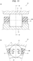
- In a rolling
bearing 10 shown inFig. 11 , a rollingelement guide cage 14B is restricted in movement in a radial direction by arolling element 13. Therolling element 13 comes into contact with atip end portion 20a of aninner holding portion 20 provided on an inner diameter side of acolumn portion 17 or atip end portion 22a of anouter holding portion 22 provided on an outer diameter side, thereby restricting movement of thecage 14B in the radial direction. - In the rolling
element guide cage 14B, as shown inFig. 12 , when thecage 14B moves in the radial direction, therolling element 13 may come into contact with a holding portion (theinner holding portion 20 and the outer holding portion 22) and engage with the holding portion in a wedge shape in a specificsingle pocket 15, and smooth rotation may be prevented. - Therefore, in general, a wedge in the
single pocket 15 is designed such that wedge angles βp and βq are as large as possible, and even when thecage 14B moves in the radial direction, it is difficult for therolling element 13 to engage with theholding portions rolling element 13 at a contact point between therolling element 13 and the holding portion and a line CL connecting a center of therolling element 13 and a center of thecage 14B. -
Patent Literature 1 discloses a cylindrical roller bearing including a cage of a rolling element guide type that prevents a wedge action of a column portion of the cage in the cylindrical roller bearing, by setting an angle formed by a line segment connecting a point where the column portion of the cage comes into contact with a cylindrical roller and a roller center and a line connecting the roller center and a cage center and extending in a radial direction, in a range of 60° or more and 72° or less. -
Patent Literature 2 discloses a rolling bearing cage in which an angle formed by an imaginary line passing through a contact point between a rolling element and a tapered surface and a center of the rolling element and an imaginary perpendicular plane passing through the center of the rolling element and perpendicular to a radial direction is set to be larger than a friction angle set based on a friction coefficient at the contact point between the rolling element and the tapered surface, and in a specific single rolling element and a pocket in which the rolling element is accommodated, it is possible to avoid edge contact between the rolling element and a pocket surface and engagement in a wedge shape. -
- Patent Literature 1:
JP2005-069282A - Patent Literature 2:
JP5870563B2 - The wedge action between the cage and the rolling element may occur not only in a single pocket but also between two pockets having different phases due to movement of the cage in the radial direction, lead or lag of the rolling element (roller), and the like.
- The rolling bearing cage and the cylindrical roller bearing disclosed in
Patent Literature 1 andPatent Literature 2 both deal with a problem of wedging in a single pocket, and do not refer to engagement of a roller due to a wedge action generated between two different pockets (not only adjacent pockets but also separate pockets) due to lead, lag, and the like of a rolling element (roller). - The present invention has been made in view of the above-described problem, and an object of the present invention is to provide a rolling bearing cage, a rolling bearing, and a method of designing a rolling bearing cage, which are capable of preventing damage to a column portion of the cage due to a wedge action formed between two pockets having different phases, and also preventing damage to the column portion of the cage due to a wedge action formed in a single pocket.
- The above object of the present invention is achieved by the following configuration.
- [1] A rolling bearing cage having a plurality of pockets for holding a plurality of rolling elements arranged between an outer ring raceway formed on an inner circumferential surface of an outer ring and an inner ring raceway formed on an outer circumferential surface of an inner ring in a rollable manner, the rolling bearing cage being guided by the plurality of rolling elements, in which
- holding portions opposed to each other in a circumferential direction in the pockets are formed into a Gothic arch shape by extending and intersecting arcs of each other, and
- a plurality of wedges are defined by tangents to tip end portions of a holding portion in a predetermined pocket and holding portions in the pockets spaced apart in the circumferential direction with respect to the predetermined pocket,
- when the holding portions are formed on an inner diameter side of the pocket and internally held, the wedge is defined by tangents to the tip end portions of the holding portions on sides where pocket surfaces are in a back-to-back relationship,
- when the holding portions are formed on an outer diameter side of the pocket and externally held, the wedge is defined by tangents to the tip end portions of the holding portions on sides where pocket surfaces face each other, and
- when a friction coefficient between the cage and the rolling elements is µ, a positive minimum value 2θmin of wedge angles 2θn of the plurality of wedges satisfies θmin > tan-1(µ).
- [2] A rolling bearing using the rolling bearing cage according to [1].
- [3] A method of designing a rolling bearing cage having a plurality of pockets for holding a plurality of rolling elements arranged between an outer ring raceway formed on an inner circumferential surface of an outer ring and an inner ring raceway formed on an outer circumferential surface of an inner ring in a rollable manner, the rolling bearing cage being guided by the plurality of rolling elements, in which
a design is made such that- a plurality of wedges are defined by tangents to tip end portions of holding portions opposed to each other in a circumferential direction in the pockets and holding portions in the pockets spaced apart in the circumferential direction with respect to the predetermined pocket,
- when the holding portions are formed on an inner diameter side of the pocket and internally held, the wedge is defined by tangents to the tip end portions of the holding portions on sides where pocket surfaces are in a back-to-back relationship,
- when the holding portions are formed on an outer diameter side of the pocket and externally held, the wedge is defined by tangents to the tip end portions of the holding portions on sides where pocket surfaces face each other, and
- when a friction coefficient between the cage and the rolling elements is µ, a positive minimum value 2θmin of wedge angles 2θn of the plurality of wedges satisfies θmin > tan-1(µ).
- According to the rolling bearing cage, the rolling bearing, and the method of designing a rolling bearing cage of the present invention, it is possible to prevent damage to a column portion of the cage due to a wedge action formed between two pockets having different phases, and it is also possible to prevent damage to the column portion of the cage due to a wedge action formed in a single pocket.
-
- [
Fig. 1 ] (a) ofFig. 1 is a cross-sectional view of a rolling bearing having an internally held cage according to a first embodiment of the present invention, and (b) ofFig. 1 is a cross-sectional view taken along line I-I in (a) ofFig. 1 . - [
Fig. 2] Fig. 2 is a schematic cross-sectional view showing wedge angles between pockets of the cage shown inFig. 1 spaced apart from each other in a circumferential direction due to internal holding. - [
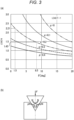
Fig. 3 ] (a) ofFig. 3 is a graph showing a relationship between a wedge angle and a load, and (b) ofFig. 3 is a schematic view showing a relationship between a wedge angle and a force. - [
Fig. 4 ] (a) ofFig. 4 is a graph showing a relationship between a friction coefficient and a wedge angle, and (b) is a table showing the relationship between the friction coefficient and the wedge angle. - [
Fig. 5 ] (a) ofFig. 5 is a view showing a positional relationship between a pocket and a rolling element in the related art, and (b) ofFig. 5 is a view showing a positional relationship between a pocket and a rolling element in a reference example. - [
Fig. 6] Fig. 6 is a cross-sectional view of a rolling bearing having an externally held cage according to a second embodiment of the present invention. - [
Fig. 7] Fig. 7 is a schematic cross-sectional view showing wedge angles between pockets of the cage shown inFig. 6 spaced apart from each other in the circumferential direction due to external holding. - [
Fig. 8] Fig. 8 is a schematic cross-sectional view of a rolling bearing having both-held cages according to a third embodiment of the present invention. - [
Fig. 9 ] (a) ofFig. 9 is a cross-sectional view of a both-held cage formed of a single arc, (b) ofFig. 9 is a cross-sectional view of the both-held cage in which an outer holding portion and an inner holding portion are connected by a common tangent, (c) ofFig. 9 is a cross-sectional view of the both-held cage in which the outer holding portion and the inner holding portion are connected by a straight line, and (d) ofFig. 9 is a cross-sectional view of the both-held cage in which the outer holding portion and the inner holding portion intersect at an intersection point. - [
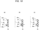
Fig. 10 ] (a) to (c) ofFig. 10 are schematic views showing tip end portions of the holding portions. - [
Fig. 11 ] (a) ofFig. 11 is a cross-sectional view of a rolling bearing including a rolling element guide cage in the related art, and (b) ofFig. 11 is a cross-sectional view taken along line XI-XI in (a) ofFig. 11 . - [
Fig. 12 ] (a) ofFig. 12 is a side view showing an angle of an externally held wedge in a single pocket, and (b) ofFig. 12 is a side view showing an angle of an internally held wedge in a single pocket. - Hereinafter, a rolling bearing cage according to each embodiment of the present invention and a rolling bearing including the rolling bearing cage will be described in detail with reference to the drawings.
- As shown in (a) and (b) in
Fig. 1 , a rollingbearing 10 according to the present embodiment includes anouter ring 11 having anouter ring raceway 11a formed on an inner circumferential surface thereof, aninner ring 12 having aninner ring raceway 12a formed on an outer circumferential surface thereof,cylindrical rollers 13 which are a plurality of rolling elements disposed between theouter ring raceway 11a and theinner ring raceway 12a, and acage 14 having a plurality ofpockets 15 for holding the plurality ofcylindrical rollers 13 in a rollable manner. - The
inner ring 12 includesannular flange portions 12b protruding to an outer diameter side on both sides in an axial direction, and restricts movement of thecylindrical roller 13 in the axial direction. - In the present embodiment, the
outer ring 11, theinner ring 12, and thecylindrical roller 13 are made of iron, and thecage 14 is made of synthetic resin. - Examples of the synthetic resin material used for the
cage 14 include phenol resin containing a basic material. As the basic material, paper, cotton fabric, asbestos fabric, glass fiber fabric and nylon fabric may be used for a laminated plate, and wood powder, cotton, pulp, asbestos, mica, glass fiber, or the like may be used for a molded product. Resin such as polyamide, polyacetal, polyether ether ketone, polyimide, or polyphenylene sulfide may be used, and a reinforcing material such as glass fiber, carbon fiber, or aramid fiber may be added as necessary. Further, thecage 14 may be made of a copper alloy or iron plated with silver or the like. - The
cage 14 includes a pair ofannular portions 16 formed on both sides in the axial direction, and a plurality ofcolumn portions 17 connecting the pair ofannular portions 16 in the axial direction and formed at predetermined intervals in a circumferential direction. Thepocket 15 is formed between the pair ofannular portions 16 andadjacent column portions 17. - As shown in (b) of
Fig. 1 , thecage 14 is an internally held rolling element guide cage, and side surfaces of thecolumn portions 17 opposed to each other in the circumferential direction have aninner holding portion 20 that is curved toward an inner diameter side of thepocket 15, and outer diameter sides from the inner holdingportion 20 areplanes 21 parallel to each other. Theinner holding portion 20 may be formed over theentire pocket 15 in the axial direction, or may be divided in the axial direction and formed symmetrically. - Accordingly, when the
cage 14 and thecylindrical roller 13 move relative to each other in a radial direction, thecage 14 does not come into contact with theouter ring 11 and theinner ring 12, and atip end portions 20a of the inner holdingportion 20 come into contact with thecylindrical roller 13, thereby restricting movement of thecage 14 in the radial direction. That is, when thecage 14 is moved upward from a state shown in the drawing, the inner holdingportion 20 abuts against thecylindrical roller 13 and the movement is restricted. When thecage 14 is moved downward, the inner holdingportion 20 on an opposite side by 180° comes into contact with thecylindrical roller 13 and the movement is restricted. - When a cross section of the
cage 14 is viewed in the axial direction, the inner holdingportion 20 is formed with a radius of curvature R1 larger than a radius r of thecylindrical roller 13, and theinner holding portions 20 opposed to each other in the circumferential direction form a Gothic arch shape by extending and intersecting arcs of each other. - Further, referring to
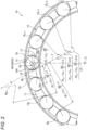
Fig. 2 , between a plurality ofpockets 15 spaced in the circumferential direction, when thecage 14 moves in the radial direction from a neutral position and twocylindrical rollers 13 move from neutral positions to a front side (leading side) and a rear side (lagging side) in a direction of orbital motion, and eachcylindrical roller 13 comes into contact with thetip end portions 20a of theinner holding portions 20 on sides where the pocket surfaces are in a back-to-back relationship, a wedge Win (n is a positive integer starting from 1) is formed. At this time, an angle formed by a tangent T to thetip end portions 20a forms a wedge angle 2θn (n is a positive integer starting from 1) between the plurality ofpockets 15. InFig. 2 , only wedges Wi1 and Wi2 are shown. - That is, in
Fig. 2 , the wedge angle 2θn is formed by the tangent T to thetip end portions 20a of theinner holding portions 20 on the sides where the pocket surfaces are in a back-to-back relationship of a pair ofinner holding portions 20 in a predetermined pocket 15 (reference pocket 15A) and a pair ofinner holding portions 20 in each pocket 15n (n: 1, 2, ..., z-1 (z is the total number of pockets)) spaced apart in the circumferential direction with respect to thepredetermined pocket 15A. - In the present embodiment, in order to prevent engagement of the wedges Win by the two
pockets 15 having different phases, a design is made such that a positive minimum value 2θmin of wedge angles 2θn of the plurality of wedges Win satisfies θmin > tan-1(µ). Here, µ is a friction coefficient between thecage 14 and thecylindrical roller 13. - Therefore, for example, when the friction coefficient under oil lubrication in which the
cage 14 is made of resin and thecylindrical roller 13 is made of iron is in a range of 0.10 or less, a design is made such that the positive minimum value 2θmin of the wedge angles 2θn exceeds 11.4° based on a relationship in a graph inFig. 4 to be described later. - Hereinafter, in order to prevent engagement of the wedges Win by the two
pockets 15 having different phases, a reason why the design is made such that the positive minimum value 2θmin of the wedge angles 2θn of the plurality of wedges Win satisfies θmin > tan-1(µ) will be described below. - As shown in
Fig. 2 , the wedge angle 2θn formed betweendifferent pockets 15 is different for each combination ofpockets 15, and in thecage 14 having the total number of pockets Z, the wedge angle 2θn formed between thereference pocket 15A and an n-th pocket 15n in a circumferential direction counterclockwise from thereference pocket 15A is represented by the following formula (1) using an angle α0 formed by a line L1 connecting a pocket diameter center (center of curvature of the inner holding portion 20) O1 and thetip end portion 20a of the inner holdingportion 20 and a line L2 perpendicular to a symmetry line L3 of thepockets 15. The symmetry line L3 is a line that connects an intermediate position of thepocket 15 in the circumferential direction and a center C of thecage 14 along the radial direction.
-
Fig. 2 shows a state in which thecylindrical rollers 13 are arranged at equal intervals in the circumferential direction and thecage 14 is located at the neutral position. The neutral position refers to a case where a rotation center of the rollingbearing 10 and the center C of thecage 14 coincide with each other and the center O2 of thecylindrical roller 13 is on the symmetry line L3 of thepockets 15. - According to the formula (1), the wedge angle 2θn formed between
different pockets 15 varies for eachpocket 15 at a pitch of -360/Z, and the wedge angle 2θmin, which always has a positive minimum value, is present therein. A negative wedge angle 2θn does not cause a problem since the negative wedge angle 2θn is a direction in which a wedge is removed. In the present embodiment, a force generated by the wedge Win is reduced by designing the wedge angle 2θn such that the positive minimum value 2θmin is as large as possible. - Specifically, for example, when 2α0 = 43 and Z = 18, the wedge angles 2θn of the
pockets 15 are +23°, +3°, -17°, -37°, ... in an order of 2θ1, 2θ2, 2θ3, 2θ4, 2θ5, .... At this time, 2θ2 = +3° forms a positive minimum wedge angle. - In order to increase the minimum wedge angle 2θn, adjustment such as changing the radius of curvature of the inner holding
portion 20 in thepocket 15 is performed such that when 2α0 = 37°, the wedge angles 2θn of thepockets 15 are +17°, -3°, -23°, and -43°..., and the positive minimum value of the wedge angle 2θmin is 2θ1 = +17°. Accordingly, by increasing the positive minimum value 2θmin of the wedge angle from +3° to + 17°, the force caused by the wedge Win can be reduced. - A relationship between the wedge angle and the force is represented by F = 2 × N × (µ × cosθ + sinθ) using the friction coefficient µ in the drawing in which the wedge shown in (b) of
Fig. 3 is driven into an object. F is a force for driving a wedge, 2θ is a wedge angle, N is a reaction force from an object into which the wedge is driven, and the reaction force of N is a force that the object receives from the wedge. - A graph of (a) of
Fig. 3 is obtained by setting F = 1N in the above calculation formula. For example, assuming that the wedge angle 2θ is 3° (θ = 1.5°) and 17° (θ = 8.5°), a material for thecage 14 is resin, a material for thecylindrical roller 13 is iron, and the friction coefficient µ between the resin and the iron is 0.2, the force N generated by the wedge becomes N = 2.21 when the wedge angle 2θ is 3° and N = 1.45 when the wedge angle 2θ is 17°, and the force (N) generated by the wedge can be reduced by increasing the wedge angle 2θ. That is, a risk of damage to thecage 14 is reduced. - As shown in
Fig. 4 , whether the driven wedge will be removed naturally depends on a friction angle λ, which is determined by the relational expression λ = tan-1(µ) between the friction coefficient µ and the friction angle λ. In other words, if θ > λ = tan-1(µ), no force is required to remove the wedge, and if θ < λ = tan-1(µ), a force is required to remove the wedge. If the wedge is not naturally removed, the force caused by the wedge continues to be applied to thecage 14, which causes a risk of damage to thecage 14. Therefore, it is desirable to set the wedge angle to 2θ so that the wedge can be removed naturally without a force for removing the wedge. - When the
cage 14 is made of nylon resin and thecylindrical roller 13 is made of steel, the friction coefficient µ under oil lubrication is indicated by 0.10 to 0.16 (according to the literature "mechanical properties of plastic for processing and design"). According to the literature, the friction coefficient µ is about 0.16 under an extremely light load environment, and the friction coefficient tends to decrease to about 0.1 as the load increases. Considering a mode in which the column portion of the cage is damaged, it is assumed that a surface pressure that the column portion receives from thecylindrical roller 13 is high, and thus the friction coefficient µ at this time is presumed to be about 0.1. When the friction coefficient µ = 0.10, the friction angle λ is λ = 5.7° based on the above equation. Accordingly, by setting the positive minimum value 2θmin of the wedge angles 2θn to be more than 11.4° (θmin = 5.7°), even when the cage and thecylindrical roller 13 are engaged with each other in a wedge shape, the wedge is naturally removed, and thus a load of force due to the wedge does not continue, and damage to the cage can be reduced. - When the friction coefficient µ = 0.16, the friction angle λ = 9.1°, so that a greater effect can be obtained by setting the positive minimum value 2θmin of the wedge angle 2θ to 18.2° (θmin = 9.1°) or more. Accordingly, damage to the
cage 14 caused due to a wedge action between pockets having different phases can be prevented. - In the present embodiment, a shape of the inner holding
portion 20 is Gothic arch to control the wedge angle 2θn between the plurality ofpockets 15. This is because, in designing thecage 14 and the rollingbearing 10, the wedge angle 2θn between thepockets 15 can be freely controlled without being subjected to functional restrictions. - For example, as another design method of controlling the wedge angle 2θn between the
pockets 15, there are the following (A) to (D), all of which have the following problems and restrictions. - When it is considered to change the pocket diameter using the non-Gothic arch, increasing the pocket diameter increases a gap in the circumferential direction between the pocket and the rolling element, resulting in problems such as cage noise due to a collision between the pocket and the rolling element, and a decrease in strength due to a decrease in a wall thickness of a column of the cage.
- When the inner diameter of the cage is reduced, there is a concern of impact with a flange of the inner ring at the time of assembling the bearing, and thus there is a limit in an adjustment range.
- When the inner diameter of the cage is increased, an opening width of the holding portion is increased, and the wedge is likely to be engaged in a single pocket, and further, the cage becomes thinner in the radial direction, resulting in a decrease in strength.
- When the number of rolling elements is forcibly increased, the column portion of the cage become thin, and the strength decreases. On the other hand, when the number of rolling elements is reduced, a basic rated load of the bearing is reduced. The number of rolling elements is a parameter that affects the basic rated load of the bearing, and thus cannot be easily changed.
- When the PCD of the pocket is shifted toward the outer diameter side, a diametrical gap between the pocket of the cage and the rolling element is eliminated, and thus there is a limit in the adjustment range. On the other hand, when the PCD of the pocket is shifted to the inner diameter side, the opening width of the holding portion is increased, and the wedge angle is reduced, so that a wedge is easily engaged in a single pocket.
- Even when the angle of the wedge between the pockets is controlled using the Gothic arch, the opening width of the holding portion is increased by increasing the radius of curvature R1 of the holding portion, so that a wedge is likely to be engaged in the single pocket. However, as compared with the case where the opening width of the holding portion is increased by the above-described measures such as (B) change the inner diameter of the cage and (D) shift the PCD of the pocket in the radial direction, the opening width of the pocket is necessarily narrower in the case of the Gothic arch, so that a wedge is less likely to be engaged in the single pocket.
- Hereinafter, when the wedge angle between different pockets is controlled using a Gothic arch according to the present embodiment, compared with a case where the wedge angle is controlled using a non-Gothic arch, it will be described that an opening width of the holding portion is reduced, that is, a wedge is less likely to be engaged in the single pocket.
- When a
cage 14C shown in (a) ofFig. 5 is in a neutral position, in the inner holdingportion 20 in which the pocket diameter center O1 (arc center of the inner holding portion) and the roller center O2 coincide with each other in a design in the related art, α0, which is a parameter in the formula (1) for determining the wedge angle 2θn in the formula (1), is formed by the line L1 connecting the pocket diameter center O1 and thetip end portion 20a of the inner holdingportion 20 and the line L2 perpendicular to the symmetry line L3 of thepockets 15. The opening width Wc of the inner holdingportion 20 at this time is Wc = 2R0 × cosα0. A pocket width P of thecage 14C is P = 2 × R0. - Here, the number Z of the
cylindrical rollers 13 is a parameter that greatly affects a load loading capability of the bearing, and it is difficult to change the number Z unless there is a particular reason. If the wedge angle 2θn betweendifferent pockets 15 is changed without changing the number Z ofcylindrical rollers 13, it is necessary to change a value of α0. - In another
cage 14D shown in (b) ofFig. 5 , α0 is changed to α0 by shifting the pocket diameter center O1 in the radial direction by Cy without changing the radius of curvature R0 of thepockets 15, that is, the wedge angle 2θn between thepockets 15 is changed. An opening width Wa of the inner holdingportion 20 at this time is Wa = 2R0 × cosα0. - On the other hand, in the
cage 14 according to the present embodiment shown in (b) ofFig. 1 , the pocket diameter is R1 (where R0 < R1), and the pocket diameter center O1 is shifted by Cx on an axis of the line L2 to form a Gothic arch, and an angle formed by the line L1 connecting the pocket diameter center O1 and thetip end portion 20a of the inner holdingportion 20 and the line L2 perpendicular to the symmetry line L3 of thepockets 15 is α0. At this time, an opening width Wb of the inner holdingportion 20 is Wb = 2 × (R1 × cosα0 - R1 + P/2). - Accordingly, a difference Wa - Wb between the pocket opening widths Wa and Wb is Wa - Wb = 2 × (R1 - R0) × (1 - cosα0). Since R1 - R0 > 0 and (1 - cosα0) > 0, the difference between the pocket opening widths Wa - Wb > 0 is obtained. In other words, Wa > Wb is always satisfied, and even when the wedge angle 2θn formed between
different pockets 15 is the same, the opening width Wb of the inner holdingportion 20 can be made smaller in a case of a Gothic arch design. That is, engagement of the wedge in thesingle pocket 15 can be reduced. - As described above, of the pair of
inner holding portions 20 in different pockets, the wedge angle 2θn of the plurality of wedges Win is implemented by the tangents T to thetip end portions 20a of theinner holding portions 20 on the sides where the pocket surfaces are in a back-to-back relationship with each other, and when the friction coefficient between thecage 14 and thecylindrical rollers 13 is µ, by making the positive minimum value 2θmin among the wedge angle 2θn of a plurality of wedges satisfy θmin > tan-1(µ), a risk of damage to thecage 14 can be significantly reduced. - Therefore, the rolling bearing according to the present embodiment can be suitably used, in particular, as a bearing that may be operated under an operation condition that a negative radial clearance is over an entire circumference, for example, a cylindrical roller bearing that supports a main shaft of a machine tool.
- In the present embodiment, when a wedge angle formed between different pockets is controlled, the
inner holding portions 20 opposed to each other in the circumferential direction in the pockets are formed in a Gothic arch shape formed by extending and intersecting arcs of each other, and damage to thecolumn portion 17 of thecage 14 due to a wedge action formed in a single pocket can be prevented. - Next, the rolling bearing cage according to the second embodiment and a rolling bearing including the rolling bearing cage will be described.
- In the rolling
element guide cage 14 according to the present embodiment, as shown inFig. 6 , an outer holdingportion 22 is formed on an outer diameter side of thepocket 15 instead of the inner holdingportion 20 formed on the inner diameter side of thepocket 15. - As shown in
Fig. 6 , the side surfaces of thecolumn portions 17 of thecage 14 opposed to each other in the circumferential direction have the outer holdingportion 22 that is curved toward the outer diameter side of thepockets 15, and the inner diameter sides from the outer holdingportion 22 areplanes 23 parallel to each other. - Accordingly, when the
cage 14 and thecylindrical roller 13 move relative to each other in the radial direction, thecylindrical roller 13 comes into contact with atip end portion 22a of the outer holdingportion 22 that is opposed to the outer diameter side of thepocket 15, thereby restricting movement of thecage 14 in the radial direction. - When the cross section of the
cage 14 is viewed in the axial direction, the outer holdingportion 22 has a radius of curvature R2 larger than the radius r of thecylindrical roller 13, and theouter holding portions 22 opposed to each other in the circumferential direction are extended and cross arcs of each other to form a Gothic arch shape. -
Fig. 7 is a side view showing the wedge angle 2θn between thepockets 15 spaced apart in the circumferential direction in thecage 14 in which the outer holdingportion 22 is formed on the outer diameter side of thepockets 15. When the outer holdingportion 22 is formed on the outer diameter side of thepocket 15, the wedge angle 2θn is defined by an angle formed by tangents T to thetip end portions 22a of theouter holding portions - In a case of outer holding, the wedge angles 2θn formed between
different pockets 15 are different for each combination ofpockets 15. In thecage 14 having the total number of pockets Z, the angle 2θn of the wedge formed between thereference pocket 15A and an n-th pocket 15n from thereference pocket 15A toward an adjacent side satisfies the formula (1) described inFig. 2 , that is, 2θn = 2α0 - 360n/Z, using the angle α0 formed by the line L1 connecting the pocket diameter center O1 and thetip end portion 22a of the outer holdingportion 22 and the line L2 perpendicular to the symmetry line L3 of thepockets 15. - Accordingly, as in a case of the inner holding
portion 20, when the friction coefficient between thecage 14 and thecylindrical rollers 13 is µ, the positive minimum value 2θmin of the plurality of wedge angles 2θn is set to satisfy θmin > tan-1(µ), and a force generated by a wedge can be reduced, reducing a risk of damage to thecage 14. - In the present embodiment, when a wedge angle formed between different pockets is controlled, the
outer holding portions 22 opposed to each other in the circumferential direction in the pockets are formed in a Gothic arch shape by extending and intersecting arcs of each other, and damage to the column portion of the cage due to a wedge action formed in a single pocket can be prevented. - Other configurations and operations are similar as those of the first embodiment.
- Next, the rolling bearing cage according to the third embodiment and a rolling bearing including the rolling bearing cage will be described. In the present embodiment, as shown in
Fig. 8 , thecage 14 is a both-held cage having both the inner holdingportion 20 and the outer holdingportion 22 provided at the same time. - In this
cage 14 as well, by forming the inner holdingportion 20 and the outer holdingportion 22 using a Gothic arch and setting the positive minimum value 2θmin of the wedge angle 2θn betweendifferent pockets 15 such that θmin > tan-1(µ) is satisfied for both the inner holdingportion 20 and the outer holdingportion 22, a force generated by a wedge can be reduced. Since an engagement force by the wedge cannot be continued, a risk of damage to thecage 14 is reduced. - As shown in (a) of
Fig. 9 , the inner holdingportion 20 and the outer holdingportion 22 may be continuously formed in a single arc. As shown in (b) ofFig. 9 , the radius of curvature R1 of the inner holdingportion 20 and the radius of curvature R2 of the outer holdingportion 22 may be different, and both radii may be connected by a common tangent. As shown in (c) ofFig. 9 , the radius of curvature R1 of the inner holdingportion 20 and the radius of curvature R2 of the outer holdingportion 22 may be different, and the inner holdingportion 20 and the outer holdingportion 22 may be connected by a commonstraight line 24. As shown in (d) ofFig. 9 , the radius of curvature R1 of the inner holdingportion 20 and the radius of curvature R2 of the outer holdingportion 22 may be different, and the inner holdingportion 20 and the outer holdingportion 22 may intersect at anintersection 25 to form double holding. - The present invention is not limited to the above embodiment, and can be appropriately modified, improved, or the like.
- For example, as shown in (a) to (c) of
Fig. 10 , thetip end portion 20a of the inner holdingportion 20 and thetip end portion 22a of the outer holdingportion 22 may be end point portions of arcs with radii of curvature R1 and R2 forming the holdingportions - Specifically, as shown in (a) of
Fig. 10 , an intersection between an inner circumferential surface of thecage 14 and the inner holdingportion 20 and an intersection between an outer circumferential surface of thecage 14 and the outer holdingportion 22 may betip end portions Fig. 10 , when an intersection between the inner circumferential surface of thecage 14 and the inner holdingportion 20 and an intersection between the outer circumferential surface of thecage 14 and the outer holdingportion 22 are round chamfering, connection points of the holdingportions tip end portions Fig. 10 , when an intersection between the inner circumferential surface of thecage 14 and the inner holdingportion 20 and an intersection between the outer circumferential surface of thecage 14 and the outer holdingportion 22 are chamfered with flat surfaces, connection points of the holdingportions tip end portions - In the above embodiment, the cylindrical roller cage and the cylindrical roller bearing in which the rolling elements are cylindrical rollers have been described, but the present invention is also applicable to a ball bearing cage and a ball bearing in which the rolling elements are balls.
- As described above, the following matters are disclosed in the present specification.
- (1) A rolling bearing cage having a plurality of pockets for holding a plurality of rolling elements arranged between an outer ring raceway formed on an inner circumferential surface of an outer ring and an inner ring raceway formed on an outer circumferential surface of an inner ring in a rollable manner, the rolling bearing cage being guided by the plurality of rolling elements, in which
- holding portions opposed to each other in a circumferential direction in the pockets are formed into a Gothic arch shape by extending and intersecting arcs of each other, and
- a plurality of wedges are defined by tangents to tip end portions of a holding portion in a predetermined pocket and holding portions in the pockets spaced apart in the circumferential direction with respect to the predetermined pocket,
- when the holding portions are formed on an inner diameter side of the pocket and internally held, the wedge is defined by tangents to the tip end portions of the holding portions on sides where pocket surfaces are in a back-to-back relationship,
- when the holding portions are formed on an outer diameter side of the pocket and externally held, the wedge is defined by tangents to the tip end portions of the holding portions on sides where pocket surfaces face each other, and
- when a friction coefficient between the cage and the rolling elements is µ, a positive minimum value 2θmin of wedge angles 2θ of the plurality of wedges satisfies θmin > tan-1(µ).
- According to this configuration, it is possible to prevent damage to a column portion of the cage due to a wedge action formed between two pockets having different phases, and it is also possible to prevent damage to the column portion of the cage due to a wedge action formed in a single pocket.
- (2) The rolling bearing cage according to (1), in which
- a positive minimum value 2θmin of the wedge angles 2θ of the plurality of wedges exceeds 11.4°.
- According to this configuration, when the friction coefficient under oil lubrication in which the cage is made of resin and the rolling element is made of iron is in a range of 0.10 or less, it is possible to prevent engagement of a wedge due to two pockets having different phases, and it is possible to prevent damage to the column portion of the cage.
- (3) The rolling bearing cage according to (1) or (2), in which
- a radius of curvature of an arc of the holding portion is larger than a radius of the rolling element.
- According to this configuration, the holding portions opposed to each other in the circumferential direction in the pockets can be formed in a Gothic arch shape.
- (4) The rolling bearing cage according to any one of (1) to (3), in which
- the rolling bearing cage is for a cylindrical roller bearing.
- According to this configuration, when the rolling bearing cage is used as a cylindrical roller bearing cage, damage to the column portion of the cage can be prevented.
- (5) The rolling bearing cage according to any one of (1) to (4), in which
- the rolling bearing cage is used under an operation condition that a negative radial clearance is over an entire circumference.
- According to this configuration, even when the cage is used under the condition that a negative radial clearance is over the entire circumference, there is no possibility that the column portion of the cage is damaged.
- (6) A rolling bearing using the rolling bearing cage according to any one of (1) to (5).
According to this configuration, there is no possibility that the cage is damaged, and a highly reliable rolling bearing is obtained. - (7) The rolling bearing according to (5), in which
- the rolling bearing supports a main shaft of a machine tool.
- According to this configuration, the main shaft of the machine tool can be supported by the highly reliable rolling bearing.
- (8) A method of designing a rolling bearing cage having a plurality of pockets for holding a plurality of rolling elements arranged between an outer ring raceway formed on an inner circumferential surface of an outer ring and an inner ring raceway formed on an outer circumferential surface of an inner ring in a rollable manner, the rolling bearing cage being guided by the plurality of rolling elements, in which
a design is made such that- a plurality of wedges are defined by tangents to tip end portions of holding portions opposed to each other in a circumferential direction in the pockets and holding portions in the pockets spaced apart in the circumferential direction with respect to the predetermined pocket,
- when the holding portions are formed on an inner diameter side of the pocket and internally held, the wedge is defined by tangents to the tip end portions of the holding portions on sides where pocket surfaces are in a back-to-back relationship,
- when the holding portions are formed on an outer diameter side of the pocket and externally held, the wedge is defined by tangents to the tip end portions of the holding portions on sides where pocket surfaces face each other, and
- when a friction coefficient between the cage and the rolling elements is µ, a positive minimum value 2θmin of wedge angles 2θn of the plurality of wedges satisfies θmin > tan-1(µ).
- According to this configuration, it is possible to design a cage capable of preventing damage to the column portion of the cage due to a wedge action formed between two pockets having different phases, and preventing damage to the column portion of the cage due to a wedge action formed in a single pocket.
- Although the embodiment and the variation thereof are described above with reference to the drawings, it is needless to mention that the present invention is not limited to these examples. It is apparent for those skilled in the art to which the present disclosure belongs that various modified examples or corrected examples are conceivable within the scope recited in the claims, and it is understood that the above falls within the technical scope of the present invention. In addition, the components described in the above embodiments may be combined in any manner without departing from the spirit of the invention.
- The present application is based on a
Japanese patent application (No. 2022-044005) filed on March 18, 2022 -
- 10 rolling bearing
- 11 outer ring
- 11a outer ring raceway
- 12 inner ring
- 12a inner ring raceway
- 13 cylindrical roller (rolling element)
- 14 cage (rolling bearing cage and cylindrical roller bearing cage)
- 15, 15A, 15n pocket
- 20 inner holding portion (holding portion)
- 20a, 22a tip end portion
- 22 outer holding portion (holding portion)
- R1 radius of curvature of inner holding portion
- R2 radius of curvature of outer holding portion
- r radius of rolling element
- T tangent to tip end portion
- 2θn wedge angle
Claims (8)
- A rolling bearing cage having a plurality of pockets for holding a plurality of rolling elements arranged between an outer ring raceway formed on an inner circumferential surface of an outer ring and an inner ring raceway formed on an outer circumferential surface of an inner ring in a rollable manner, the rolling bearing cage being guided by the plurality of rolling elements, whereinholding portions opposed to each other in a circumferential direction in the pockets are formed into a Gothic arch shape by extending and intersecting arcs of each other, anda plurality of wedges are defined by tangents to tip end portions of a holding portion in a predetermined pocket and holding portions in the pockets spaced apart in the circumferential direction with respect to the predetermined pocket,when the holding portions are formed on an inner diameter side of the pocket and internally held, the wedge is defined by tangents to the tip end portions of the holding portions on sides where pocket surfaces are in a back-to-back relationship,when the holding portions are formed on an outer diameter side of the pocket and externally held, the wedge is defined by tangents to the tip end portions of the holding portions on sides where pocket surfaces face each other, andwhen a friction coefficient between the cage and the rolling elements is µ, a positive minimum value 2θmin of wedge angles 2θn of the plurality of wedges satisfies θmin > tan-1(µ).
- The rolling bearing cage according to claim 1, wherein
a positive minimum value 2θmin of the wedge angles 2θn of the plurality of wedges exceeds 11.4°. - The rolling bearing cage according to claim 1 or 2, wherein
a radius of curvature of an arc of the holding portion is larger than a radius of the rolling element. - The rolling bearing cage according to any one of claims 1 to 3, wherein
the rolling bearing cage is for a cylindrical roller bearing. - The rolling bearing cage according to any one of claims 1 to 4, wherein
the rolling bearing cage is used under an operation condition that a negative radial clearance is over an entire circumference. - A rolling bearing using the rolling bearing cage according to any one of claims 1 to 5.
- The rolling bearing according to claim 6, wherein
the rolling bearing supports a main shaft of a machine tool. - A method of designing a rolling bearing cage having a plurality of pockets for holding a plurality of rolling elements arranged between an outer ring raceway formed on an inner circumferential surface of an outer ring and an inner ring raceway formed on an outer circumferential surface of an inner ring in a rollable manner, the rolling bearing cage being guided by the plurality of rolling elements, wherein
a design is made such thata plurality of wedges are defined by tangents to tip end portions of holding portions opposed to each other in a circumferential direction in the pockets and holding portions in the pockets spaced apart in the circumferential direction with respect to the predetermined pocket,when the holding portions are formed on an inner diameter side of the pocket and internally held, the wedge is defined by tangents to the tip end portions of the holding portions on sides where pocket surfaces are in a back-to-back relationship,when the holding portions are formed on an outer diameter side of the pocket and externally held, the wedge is defined by tangents to the tip end portions of the holding portions on sides where pocket surfaces face each other, andwhen a friction coefficient between the cage and the rolling elements is µ, a positive minimum value 2θmin of wedge angles 2θn of the plurality of wedges satisfies θmin > tan-1(µ).
Applications Claiming Priority (2)
| Application Number | Priority Date | Filing Date | Title |
|---|---|---|---|
| JP2022044005A JP7635743B2 (en) | 2022-03-18 | 2022-03-18 | Rolling bearing retainer, rolling bearing, and method for designing a rolling bearing retainer |
| PCT/JP2023/003294 WO2023176181A1 (en) | 2022-03-18 | 2023-02-01 | Cage for rolling bearing, rolling bearing, and method of designing cage for rolling bearing |
Publications (3)
| Publication Number | Publication Date |
|---|---|
| EP4495445A1 true EP4495445A1 (en) | 2025-01-22 |
| EP4495445A4 EP4495445A4 (en) | 2025-08-20 |
| EP4495445B1 EP4495445B1 (en) | 2026-03-25 |
Family
ID=88022789
Family Applications (1)
| Application Number | Title | Priority Date | Filing Date |
|---|---|---|---|
| EP23770143.8A Active EP4495445B1 (en) | 2022-03-18 | 2023-02-01 | Cage for rolling bearing, rolling bearing, and method of designing cage for rolling bearing |
Country Status (5)
| Country | Link |
|---|---|
| EP (1) | EP4495445B1 (en) |
| JP (1) | JP7635743B2 (en) |
| CN (1) | CN118891453A (en) |
| TW (1) | TW202400908A (en) |
| WO (1) | WO2023176181A1 (en) |
Family Cites Families (5)
| Publication number | Priority date | Publication date | Assignee | Title |
|---|---|---|---|---|
| JP2005069282A (en) | 2003-08-20 | 2005-03-17 | Ntn Corp | Cylindrical roller bearing |
| JP5870563B2 (en) * | 2011-09-06 | 2016-03-01 | 日本精工株式会社 | Roller bearing cage and rolling bearing |
| TWI704298B (en) * | 2016-11-04 | 2020-09-11 | 日商日本精工股份有限公司 | Cage and rolling bearing provided with it |
| JP6696610B2 (en) * | 2019-04-26 | 2020-05-20 | 日本精工株式会社 | Cage cage for rolling bearings |
| GB2598665B (en) | 2020-09-04 | 2025-07-23 | Skyworks Solutions Inc | Multi-layer piezoelectric substrate with controllable delta temperature coefficient of frequency |
-
2022
- 2022-03-18 JP JP2022044005A patent/JP7635743B2/en active Active
-
2023
- 2023-02-01 CN CN202380028316.9A patent/CN118891453A/en active Pending
- 2023-02-01 EP EP23770143.8A patent/EP4495445B1/en active Active
- 2023-02-01 WO PCT/JP2023/003294 patent/WO2023176181A1/en not_active Ceased
- 2023-02-02 TW TW112103615A patent/TW202400908A/en unknown
Also Published As
| Publication number | Publication date |
|---|---|
| JP7635743B2 (en) | 2025-02-26 |
| CN118891453A (en) | 2024-11-01 |
| TW202400908A (en) | 2024-01-01 |
| JP2023137696A (en) | 2023-09-29 |
| EP4495445A4 (en) | 2025-08-20 |
| WO2023176181A1 (en) | 2023-09-21 |
| EP4495445B1 (en) | 2026-03-25 |
Similar Documents
| Publication | Publication Date | Title |
|---|---|---|
| EP2754907B1 (en) | Rolling bearing cage and rolling bearing | |
| EP3543553B1 (en) | Rolling bearing cage and rolling bearing | |
| US7530743B2 (en) | Double row cylindrical roller bearing | |
| US9039288B2 (en) | Tapered roller bearing resin cage and tapered roller bearing | |
| US5538348A (en) | Self-aligning roller bearing with cage | |
| EP3869054B1 (en) | Angular ball bearing | |
| US7150565B1 (en) | Cylindrical roller bearing | |
| EP1816362A1 (en) | Self-aligning roller bearing with retainer and method of manufacturing the retainer for the self-aligning roller bearing | |
| EP2239473B1 (en) | Rolling bearing cage | |
| US20100098364A1 (en) | Roller with cage assembly | |
| US9829038B2 (en) | Bearing and bearing arrangement | |
| EP4495445B1 (en) | Cage for rolling bearing, rolling bearing, and method of designing cage for rolling bearing | |
| EP3744992B1 (en) | Angular ball bearing | |
| KR20190122681A (en) | Roller gear cam mechanism | |
| US10371198B2 (en) | Quad foil journal air bearing | |
| EP2042762A1 (en) | Lubrication mechanism for bearing | |
| EP3561323B1 (en) | Foil journal air bearing | |
| CN110566583A (en) | Thrust needle roller bearing | |
| EP4722553A1 (en) | Cylindrical roller bearing | |
| EP4663965A1 (en) | Rolling bearing and spindle device for machine tool | |
| JP2021134890A (en) | Cylindrical roller bearing with outer ring | |
| US20250198453A1 (en) | Tapered roller bearing | |
| US20240209892A1 (en) | Roller bearing, roller bearing unit, motor, method for manufacturing roller bearing, and method for silencing roller bearing | |
| US9732793B2 (en) | Bearing and bearing arrangement | |
| JP2006112568A (en) | Cylindrical roller bearing |
Legal Events
| Date | Code | Title | Description |
|---|---|---|---|
| STAA | Information on the status of an ep patent application or granted ep patent |
Free format text: STATUS: THE INTERNATIONAL PUBLICATION HAS BEEN MADE |
|
| PUAI | Public reference made under article 153(3) epc to a published international application that has entered the european phase |
Free format text: ORIGINAL CODE: 0009012 |
|
| STAA | Information on the status of an ep patent application or granted ep patent |
Free format text: STATUS: REQUEST FOR EXAMINATION WAS MADE |
|
| 17P | Request for examination filed |
Effective date: 20240912 |
|
| AK | Designated contracting states |
Kind code of ref document: A1 Designated state(s): AL AT BE BG CH CY CZ DE DK EE ES FI FR GB GR HR HU IE IS IT LI LT LU LV MC ME MK MT NL NO PL PT RO RS SE SI SK SM TR |
|
| DAV | Request for validation of the european patent (deleted) | ||
| DAX | Request for extension of the european patent (deleted) | ||
| A4 | Supplementary search report drawn up and despatched |
Effective date: 20250721 |
|
| RIC1 | Information provided on ipc code assigned before grant |
Ipc: F16C 19/26 20060101AFI20250715BHEP Ipc: F16C 33/46 20060101ALI20250715BHEP |
|
| GRAP | Despatch of communication of intention to grant a patent |
Free format text: ORIGINAL CODE: EPIDOSNIGR1 |
|
| STAA | Information on the status of an ep patent application or granted ep patent |
Free format text: STATUS: GRANT OF PATENT IS INTENDED |
|
| INTG | Intention to grant announced |
Effective date: 20251111 |
|
| GRAS | Grant fee paid |
Free format text: ORIGINAL CODE: EPIDOSNIGR3 |
|
| GRAA | (expected) grant |
Free format text: ORIGINAL CODE: 0009210 |
|
| STAA | Information on the status of an ep patent application or granted ep patent |
Free format text: STATUS: THE PATENT HAS BEEN GRANTED |
|
| AK | Designated contracting states |
Kind code of ref document: B1 Designated state(s): AL AT BE BG CH CY CZ DE DK EE ES FI FR GB GR HR HU IE IS IT LI LT LU LV MC ME MK MT NL NO PL PT RO RS SE SI SK SM TR |
|
| REG | Reference to a national code |
Ref country code: CH Ref legal event code: F10 Free format text: ST27 STATUS EVENT CODE: U-0-0-F10-F00 (AS PROVIDED BY THE NATIONAL OFFICE) Effective date: 20260325 Ref country code: GB Ref legal event code: FG4D |
|
| REG | Reference to a national code |
Ref country code: DE Ref legal event code: R096 Ref document number: 602023014192 Country of ref document: DE |
|
| REG | Reference to a national code |
Ref country code: IE Ref legal event code: FG4D |