EP4495433A1 - Fastener, fastening system and method - Google Patents
Fastener, fastening system and method Download PDFInfo
- Publication number
- EP4495433A1 EP4495433A1 EP23187052.8A EP23187052A EP4495433A1 EP 4495433 A1 EP4495433 A1 EP 4495433A1 EP 23187052 A EP23187052 A EP 23187052A EP 4495433 A1 EP4495433 A1 EP 4495433A1
- Authority
- EP
- European Patent Office
- Prior art keywords
- fastening
- trap
- eyelet
- support
- component
- Prior art date
- Legal status (The legal status is an assumption and is not a legal conclusion. Google has not performed a legal analysis and makes no representation as to the accuracy of the status listed.)
- Withdrawn
Links
Images

Classifications
-
- F—MECHANICAL ENGINEERING; LIGHTING; HEATING; WEAPONS; BLASTING
- F16—ENGINEERING ELEMENTS AND UNITS; GENERAL MEASURES FOR PRODUCING AND MAINTAINING EFFECTIVE FUNCTIONING OF MACHINES OR INSTALLATIONS; THERMAL INSULATION IN GENERAL
- F16B—DEVICES FOR FASTENING OR SECURING CONSTRUCTIONAL ELEMENTS OR MACHINE PARTS TOGETHER, e.g. NAILS, BOLTS, CIRCLIPS, CLAMPS, CLIPS OR WEDGES; JOINTS OR JOINTING
- F16B2/00—Friction-grip releasable fastenings
- F16B2/02—Clamps, i.e. with gripping action effected by positive means other than the inherent resistance to deformation of the material of the fastening
- F16B2/06—Clamps, i.e. with gripping action effected by positive means other than the inherent resistance to deformation of the material of the fastening external, i.e. with contracting action
- F16B2/10—Clamps, i.e. with gripping action effected by positive means other than the inherent resistance to deformation of the material of the fastening external, i.e. with contracting action using pivoting jaws
-
- F—MECHANICAL ENGINEERING; LIGHTING; HEATING; WEAPONS; BLASTING
- F16—ENGINEERING ELEMENTS AND UNITS; GENERAL MEASURES FOR PRODUCING AND MAINTAINING EFFECTIVE FUNCTIONING OF MACHINES OR INSTALLATIONS; THERMAL INSULATION IN GENERAL
- F16B—DEVICES FOR FASTENING OR SECURING CONSTRUCTIONAL ELEMENTS OR MACHINE PARTS TOGETHER, e.g. NAILS, BOLTS, CIRCLIPS, CLAMPS, CLIPS OR WEDGES; JOINTS OR JOINTING
- F16B17/00—Connecting constructional elements or machine parts by a part of or on one member entering a hole in the other and involving plastic deformation
- F16B17/006—Connecting constructional elements or machine parts by a part of or on one member entering a hole in the other and involving plastic deformation of rods or tubes to sheets or plates
-
- F—MECHANICAL ENGINEERING; LIGHTING; HEATING; WEAPONS; BLASTING
- F16—ENGINEERING ELEMENTS AND UNITS; GENERAL MEASURES FOR PRODUCING AND MAINTAINING EFFECTIVE FUNCTIONING OF MACHINES OR INSTALLATIONS; THERMAL INSULATION IN GENERAL
- F16B—DEVICES FOR FASTENING OR SECURING CONSTRUCTIONAL ELEMENTS OR MACHINE PARTS TOGETHER, e.g. NAILS, BOLTS, CIRCLIPS, CLAMPS, CLIPS OR WEDGES; JOINTS OR JOINTING
- F16B17/00—Connecting constructional elements or machine parts by a part of or on one member entering a hole in the other and involving plastic deformation
- F16B17/008—Connecting constructional elements or machine parts by a part of or on one member entering a hole in the other and involving plastic deformation of sheets or plates mutually
-
- F—MECHANICAL ENGINEERING; LIGHTING; HEATING; WEAPONS; BLASTING
- F16—ENGINEERING ELEMENTS AND UNITS; GENERAL MEASURES FOR PRODUCING AND MAINTAINING EFFECTIVE FUNCTIONING OF MACHINES OR INSTALLATIONS; THERMAL INSULATION IN GENERAL
- F16B—DEVICES FOR FASTENING OR SECURING CONSTRUCTIONAL ELEMENTS OR MACHINE PARTS TOGETHER, e.g. NAILS, BOLTS, CIRCLIPS, CLAMPS, CLIPS OR WEDGES; JOINTS OR JOINTING
- F16B2/00—Friction-grip releasable fastenings
- F16B2/20—Clips, i.e. with gripping action effected solely by the inherent resistance to deformation of the material of the fastening
- F16B2/22—Clips, i.e. with gripping action effected solely by the inherent resistance to deformation of the material of the fastening of resilient material, e.g. rubbery material
- F16B2/24—Clips, i.e. with gripping action effected solely by the inherent resistance to deformation of the material of the fastening of resilient material, e.g. rubbery material of metal
- F16B2/241—Clips, i.e. with gripping action effected solely by the inherent resistance to deformation of the material of the fastening of resilient material, e.g. rubbery material of metal of sheet metal
- F16B2/245—Clips, i.e. with gripping action effected solely by the inherent resistance to deformation of the material of the fastening of resilient material, e.g. rubbery material of metal of sheet metal external, i.e. with contracting action
-
- F—MECHANICAL ENGINEERING; LIGHTING; HEATING; WEAPONS; BLASTING
- F16—ENGINEERING ELEMENTS AND UNITS; GENERAL MEASURES FOR PRODUCING AND MAINTAINING EFFECTIVE FUNCTIONING OF MACHINES OR INSTALLATIONS; THERMAL INSULATION IN GENERAL
- F16B—DEVICES FOR FASTENING OR SECURING CONSTRUCTIONAL ELEMENTS OR MACHINE PARTS TOGETHER, e.g. NAILS, BOLTS, CIRCLIPS, CLAMPS, CLIPS OR WEDGES; JOINTS OR JOINTING
- F16B45/00—Hooks; Eyes
- F16B45/002—Eyes
-
- F—MECHANICAL ENGINEERING; LIGHTING; HEATING; WEAPONS; BLASTING
- F16—ENGINEERING ELEMENTS AND UNITS; GENERAL MEASURES FOR PRODUCING AND MAINTAINING EFFECTIVE FUNCTIONING OF MACHINES OR INSTALLATIONS; THERMAL INSULATION IN GENERAL
- F16B—DEVICES FOR FASTENING OR SECURING CONSTRUCTIONAL ELEMENTS OR MACHINE PARTS TOGETHER, e.g. NAILS, BOLTS, CIRCLIPS, CLAMPS, CLIPS OR WEDGES; JOINTS OR JOINTING
- F16B5/00—Joining sheets or plates, e.g. panels, to one another or to strips or bars parallel to them
- F16B5/06—Joining sheets or plates, e.g. panels, to one another or to strips or bars parallel to them by means of clamps or clips
- F16B5/0607—Joining sheets or plates, e.g. panels, to one another or to strips or bars parallel to them by means of clamps or clips joining sheets or plates to each other
- F16B5/0621—Joining sheets or plates, e.g. panels, to one another or to strips or bars parallel to them by means of clamps or clips joining sheets or plates to each other in parallel relationship
- F16B5/0635—Joining sheets or plates, e.g. panels, to one another or to strips or bars parallel to them by means of clamps or clips joining sheets or plates to each other in parallel relationship fastened over the edges of the sheets or plates
-
- F—MECHANICAL ENGINEERING; LIGHTING; HEATING; WEAPONS; BLASTING
- F16—ENGINEERING ELEMENTS AND UNITS; GENERAL MEASURES FOR PRODUCING AND MAINTAINING EFFECTIVE FUNCTIONING OF MACHINES OR INSTALLATIONS; THERMAL INSULATION IN GENERAL
- F16B—DEVICES FOR FASTENING OR SECURING CONSTRUCTIONAL ELEMENTS OR MACHINE PARTS TOGETHER, e.g. NAILS, BOLTS, CIRCLIPS, CLAMPS, CLIPS OR WEDGES; JOINTS OR JOINTING
- F16B5/00—Joining sheets or plates, e.g. panels, to one another or to strips or bars parallel to them
- F16B5/12—Fastening strips or bars to sheets or plates, e.g. rubber strips, decorative strips for motor vehicles, by means of clips
- F16B5/121—Fastening strips or bars to sheets or plates, e.g. rubber strips, decorative strips for motor vehicles, by means of clips fastened over the edge(s) of the sheet(s) or plate(s)
Definitions
- the present invention relates to a fastener for attaching a component to a support structure. Further, the present invention relates to a fastening system and a method for attaching a component to a support structure.
- Fasteners and fastening systems are known which are used for attaching components, such as rails or hangers, to a support structure, such as a wall or a ceiling. It is well known to temporarily attach such a fastener to a tool nose of a setting tool and then fastening the fastener to the support structure using the setting tool. During fastening, the component needs to be manually held in position between the fastener and the support structure, which in some circumstances may be cumbersome, in particular if the fastening point is poorly accessible.
- a fastener for attaching a component having an eyelet to a support structure in a fastening direction comprises a fastening element configured to be driven into the support structure and comprising a shaft that has an end face facing in the fastening direction, a clip member having a support element attached to the fastening element and a trap element configured to be moved from an open position to a closed position, wherein, in the open position, a gap having a gap width is formed between the trap element and the end face allowing placing the eyelet through the gap and over the end face onto the fastening element, and in the closed position, the gap width is reduced to trap the eyelet on the fastening element.
- the gap is completely closed in the closed position of the trap element.
- the component By trapping the eyelet on the fastening element, the component may be locked to the fastener and held in position more easily, or even without the need of manual action. In this way, for example overhead applications are facilitated.
- the clip member comprises a sheet material having a support section forming the support element, and a trap section forming the trap element.
- the sheet material has a bending section about which the trap section is bent relative to the support section when the trap element is moved from the open position to the closed position.
- the bending section is weakened, or perforated.
- the trap element comprises a hole configured to receive the fastening element.
- the fastening element is received in the hole, it is easier for a user to ensure that the gap width is reduced far enough to trap the eyelet.
- the support element comprises a bumper configured to absorb residual driving energy of the fastening element. Absorbing such a residual driving energy by the support element helps preventing the fastening element from being driven too far onto the eyelet.
- the support element is formed as an end stop for the component or eyelet against the fastening direction.
- moving the trap element to the closed position may secure the eyelet between the support element and the trap element, preventing the component from loose wobbling around during fastening.
- the end face comprises a pointed or rounded tip pointing in the fastening direction.
- the end face is flat or slightly convex or concave.
- the fastening element comprises a nail, a pin, a stud, a rivet, an anchor or a screw.
- a fastening system comprises the fastener as described herein above and the component.
- the component comprises a ceiling hanger.
- a method for attaching a component having an eyelet to a support structure in a fastening direction comprises providing a fastening system as described herein above, wherein the trap element is in the open position, placing the eyelet through the gap and over the end face onto the fastening element, moving the trap element from the open position to the closed position to trap the eyelet on the fastening element, and driving the fastening element into the support structure. It is preferred but not mandatory that the method steps are performed in the order as mentioned above. According to a preferred embodiment, moving the trap element from the open position to the closed position comprises bending the trap element relative to the support element.
- placing the eyelet onto the fastening element comprises abutting the eyelet on the support element.
- moving the trap element to the closed position may secure the eyelet between the support element and the trap element, preventing the component from loose wobbling around during fastening.
- Figs. 1-2 show a fastener 10 for attaching a component (such as shown in Figs. 3-4 ) to a support structure (not shown) in a fastening direction 20.
- the fastener 10 comprises a fastening element 30 that is configured to be driven into the support structure.
- the fastening element 30 is formed as a nail having a shaft 32 that has an end face 34 facing in the fastening direction 20 and a head 36.
- the end face 34 is formed as a pointed tip pointing in the fastening direction 20.
- the fastening element may be formed as a pin, a stud, a rivet or a screw, each in particular having a pointed or rounded tip.
- the fastener 10 further comprises a clip member 40 that has a support element 42 which is attached to the fastening element 30.
- the support element 42 is provided with a passage or bore that has a diameter that is slightly smaller than a diameter of the shaft 32, and the fastening element 30 is inserted, or press-fitted into the passage of the support element 42.
- a diameter of a passage in the support element is similar to or greater than a diameter of the shaft.
- the support element 42 comprises a bumper 43 that is formed as a curved part of the support element 42, such as a bulge or dome, and that is configured to absorb residual driving energy of the fastening element 30 when the fastening element 30 is driven into the support structure.
- the support member 42 further comprises an abutment face 49 facing in the fastening direction 20 and falling short of the end face 34 in the fastening direction 20. In the embodiment shown, the abutment face 49 surrounds the bumper 43.
- the clip member 40 further has a trap element 44 that is shown in an open position in Figs. 1-2 and that is configured to be moved from the open position to a closed position, as described below with reference to Figs. 3-4 .
- a gap 50 having a gap width w is formed between the trap element 44 and the end face 34 of the fastening element 30.
- the trap element 44 is provided with a hole 45, in particular a through hole or a blind hole.
- the hole 45 is configured to receive the fastening element, or the end face of the fastening element, as likewise described below.
- the clip member 40 comprises, or is made of a sheet material such as a sheet metal, for example iron or aluminium, or alloy, for example galvanized carbon steel or other steel.
- the sheet material has a support section that extends in a plane perpendicular to the fastening direction 20 and that forms the support element 42, a trap section that forms the trap element 44, and a bending section that forms a bending element 46 about which the trap section may be bent relative to the support section when the trap element 44 is moved from the open position to the closed position. At least in the closed position, the trap section may extend in a plane parallel to the support section, i.e. likewise in a plane perpendicular to the fastening direction 20.
- the bending element 46 is provided with a perforation 47 to weaken the bending element 46 and to ease bending the bending element 46, thereby making moving the trap element 44 from the open position to the closed position easier.
- Figs. 3-4 demonstrate a method for attaching a component 60 that has an eyelet 62, such as a holding element, for example a ceiling hanger, to a support structure (not shown) in a fastening direction.
- the component 60 comprises a wire the end of which is bent to form the eyelet 62.
- the component may comprise a sheet material bent and/or stamped to form the component and have a punch-through hole which forms the eyelet, or a threaded element having a hole that forms the eyelet.
- a fastening system is provided that comprises the component 60 and a fastener, such as the fastener 10 as shown in Figs. 1-2 .
- the fastener 10 is provided with a trap element 44 which is in the open position.
- the eyelet 62 is placed through the gap 50 and over the end face 34 onto the fastening element 30.
- the gap width w is configured to give the eyelet 62 sufficient allowance to be placed through the gap 50.
- the component 60, or the eyelet 62 abuts the support element 42, or the abutment face 49, which serves as an end stop for the eyelet 62 against the fastening direction 20.
- the eyelet is placed on the support element or between the support element and the trap element before the fastening element is inserted in or through the eyelet.
- the trap element 44 is moved, or bent from the open position ( Fig. 3 ) to the closed position ( Fig. 4 ) relative to the support element (see, arrow 70 in Fig. 3 ), thereby reducing the gap width, or closing the gap 50 to trap the eyelet 62 on the fastening element 30.
- the hole 45 provided in the trap element 44 (not shown in Figs. 3-4 ) receives the end face 34 of the fastening element 30 to facilitate closing the gap 50.
- the eyelet 62 may be secured between the support element 42 and the trap element 44 by moving the trap element 44 to the closed position.
- the step of moving the trap element from the open position to the closed position is performed by a tool, or power actuated tool, such as the tool used for driving the fastening element into a support structure, e.g. at the same time as driving the fastening element into the support structure.
- the fastening element 10 is driven into the support structure when the eyelet 62 is trapped on the fastening element 30 by the fastener 10, or the trap element 44, i.e. when the fastening system is in the configuration shown in Fig. 4 .
- a fastening tool, or power actuated fastening tool such as a nail gun or screwdriver may be used, in particular a pole tool, wherein the fastening system is placed on a tool nose of the fastening tool beforehand, in particular manually.
- the support structure may be a construction element, such as a wall or ceiling, and may be made of concrete, metal or alloy, such as steel, timber or the like.
Landscapes
- Engineering & Computer Science (AREA)
- General Engineering & Computer Science (AREA)
- Mechanical Engineering (AREA)
- Connection Of Plates (AREA)
Abstract
A fastener for attaching a component to a support structure comprises a fastening element comprising a shaft that has an end face facing in the fastening direction, a clip member having a support element and a trap element that is moved from an open position to a closed position to trap an eyelet of the component on the fastening element.
Description
- The present invention relates to a fastener for attaching a component to a support structure. Further, the present invention relates to a fastening system and a method for attaching a component to a support structure.
- Fasteners and fastening systems are known which are used for attaching components, such as rails or hangers, to a support structure, such as a wall or a ceiling. It is well known to temporarily attach such a fastener to a tool nose of a setting tool and then fastening the fastener to the support structure using the setting tool. During fastening, the component needs to be manually held in position between the fastener and the support structure, which in some circumstances may be cumbersome, in particular if the fastening point is poorly accessible.
- According to a first aspect of the invention, a fastener for attaching a component having an eyelet to a support structure in a fastening direction comprises a fastening element configured to be driven into the support structure and comprising a shaft that has an end face facing in the fastening direction, a clip member having a support element attached to the fastening element and a trap element configured to be moved from an open position to a closed position, wherein, in the open position, a gap having a gap width is formed between the trap element and the end face allowing placing the eyelet through the gap and over the end face onto the fastening element, and in the closed position, the gap width is reduced to trap the eyelet on the fastening element. According to a preferred embodiment, the gap is completely closed in the closed position of the trap element. By trapping the eyelet on the fastening element, the component may be locked to the fastener and held in position more easily, or even without the need of manual action. In this way, for example overhead applications are facilitated.
- According to an embodiment, the clip member comprises a sheet material having a support section forming the support element, and a trap section forming the trap element. According to a preferred embodiment, the sheet material has a bending section about which the trap section is bent relative to the support section when the trap element is moved from the open position to the closed position. According to an even more preferred embodiment, the bending section is weakened, or perforated.
- According to a further embodiment, the trap element comprises a hole configured to receive the fastening element. When the fastening element is received in the hole, it is easier for a user to ensure that the gap width is reduced far enough to trap the eyelet.
- According to a further embodiment, the support element comprises a bumper configured to absorb residual driving energy of the fastening element. Absorbing such a residual driving energy by the support element helps preventing the fastening element from being driven too far onto the eyelet.
- According to a further embodiment, the support element is formed as an end stop for the component or eyelet against the fastening direction. When the component or eyelet abuts on the support element, moving the trap element to the closed position may secure the eyelet between the support element and the trap element, preventing the component from loose wobbling around during fastening.
- According to a further embodiment, the end face comprises a pointed or rounded tip pointing in the fastening direction. According to another embodiment, the end face is flat or slightly convex or concave. According to another embodiment, the fastening element comprises a nail, a pin, a stud, a rivet, an anchor or a screw.
- According to a further aspect of the invention, a fastening system comprises the fastener as described herein above and the component. According to a preferred embodiment, the component comprises a ceiling hanger.
- According to a further aspect of the invention, a method for attaching a component having an eyelet to a support structure in a fastening direction comprises providing a fastening system as described herein above, wherein the trap element is in the open position, placing the eyelet through the gap and over the end face onto the fastening element, moving the trap element from the open position to the closed position to trap the eyelet on the fastening element, and driving the fastening element into the support structure. It is preferred but not mandatory that the method steps are performed in the order as mentioned above. According to a preferred embodiment, moving the trap element from the open position to the closed position comprises bending the trap element relative to the support element.
- According to a further embodiment, placing the eyelet onto the fastening element comprises abutting the eyelet on the support element. When the eyelet abuts on the support element, moving the trap element to the closed position may secure the eyelet between the support element and the trap element, preventing the component from loose wobbling around during fastening.
- The invention will be described in more detail by way of example hereinafter with reference to the drawings. The described embodiments are only possible configurations in which the individual features may however be implemented independently of each other or may be omitted.
- In the drawings:
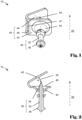
- Fig. 1
- is a perspective view of a fastener;
- Fig. 2
- is a cross-sectional view of the fastening element shown in
Fig. 1 ; - Fig. 3
- is a side view of a fastening system with a trap element in an open position; and
- Fig. 4
- is a side view of the fastening system shown in
Fig. 3 with the trap element in a closed position. -
Figs. 1-2 show afastener 10 for attaching a component (such as shown inFigs. 3-4 ) to a support structure (not shown) in afastening direction 20. - The
fastener 10 comprises afastening element 30 that is configured to be driven into the support structure. To this end, thefastening element 30 is formed as a nail having ashaft 32 that has anend face 34 facing in thefastening direction 20 and ahead 36. Theend face 34 is formed as a pointed tip pointing in thefastening direction 20. In other embodiments (not shown), the fastening element may be formed as a pin, a stud, a rivet or a screw, each in particular having a pointed or rounded tip. - The
fastener 10 further comprises aclip member 40 that has asupport element 42 which is attached to thefastening element 30. To this end, thesupport element 42 is provided with a passage or bore that has a diameter that is slightly smaller than a diameter of theshaft 32, and thefastening element 30 is inserted, or press-fitted into the passage of thesupport element 42. In non-shown embodiments, a diameter of a passage in the support element is similar to or greater than a diameter of the shaft. Thesupport element 42 comprises abumper 43 that is formed as a curved part of thesupport element 42, such as a bulge or dome, and that is configured to absorb residual driving energy of thefastening element 30 when thefastening element 30 is driven into the support structure. Thesupport member 42 further comprises anabutment face 49 facing in thefastening direction 20 and falling short of theend face 34 in thefastening direction 20. In the embodiment shown, theabutment face 49 surrounds thebumper 43. - The
clip member 40 further has atrap element 44 that is shown in an open position inFigs. 1-2 and that is configured to be moved from the open position to a closed position, as described below with reference toFigs. 3-4 . In the open position, as best seen inFig. 2 , agap 50 having a gap width w is formed between thetrap element 44 and theend face 34 of thefastening element 30. Thetrap element 44 is provided with ahole 45, in particular a through hole or a blind hole. Thehole 45 is configured to receive the fastening element, or the end face of the fastening element, as likewise described below. - The
clip member 40 comprises, or is made of a sheet material such as a sheet metal, for example iron or aluminium, or alloy, for example galvanized carbon steel or other steel. The sheet material has a support section that extends in a plane perpendicular to thefastening direction 20 and that forms thesupport element 42, a trap section that forms thetrap element 44, and a bending section that forms abending element 46 about which the trap section may be bent relative to the support section when thetrap element 44 is moved from the open position to the closed position. At least in the closed position, the trap section may extend in a plane parallel to the support section, i.e. likewise in a plane perpendicular to thefastening direction 20. Thebending element 46 is provided with aperforation 47 to weaken thebending element 46 and to ease bending thebending element 46, thereby making moving thetrap element 44 from the open position to the closed position easier. -
Figs. 3-4 demonstrate a method for attaching acomponent 60 that has aneyelet 62, such as a holding element, for example a ceiling hanger, to a support structure (not shown) in a fastening direction. In the shown embodiment, thecomponent 60 comprises a wire the end of which is bent to form theeyelet 62. In non-shown embodiments, the component may comprise a sheet material bent and/or stamped to form the component and have a punch-through hole which forms the eyelet, or a threaded element having a hole that forms the eyelet. A fastening system is provided that comprises thecomponent 60 and a fastener, such as thefastener 10 as shown inFigs. 1-2 . In a preferred embodiment, thefastener 10 is provided with atrap element 44 which is in the open position. - In a first step which in particular is performed manually, the
eyelet 62 is placed through thegap 50 and over theend face 34 onto thefastening element 30. The gap width w is configured to give theeyelet 62 sufficient allowance to be placed through thegap 50. In a preferred embodiment, thecomponent 60, or theeyelet 62 abuts thesupport element 42, or theabutment face 49, which serves as an end stop for theeyelet 62 against thefastening direction 20. In non-shown embodiments, the eyelet is placed on the support element or between the support element and the trap element before the fastening element is inserted in or through the eyelet. - In a further step which in particular is performed manually, the
trap element 44 is moved, or bent from the open position (Fig. 3 ) to the closed position (Fig. 4 ) relative to the support element (see,arrow 70 inFig. 3 ), thereby reducing the gap width, or closing thegap 50 to trap theeyelet 62 on thefastening element 30. Thehole 45 provided in the trap element 44 (not shown inFigs. 3-4 ) receives theend face 34 of thefastening element 30 to facilitate closing thegap 50. By abutting on thesupport element 42, or theabutment face 49, theeyelet 62 may be secured between thesupport element 42 and thetrap element 44 by moving thetrap element 44 to the closed position. In this way, loose wobbling around by thecomponent 60 during fastening may be prevented. The step of moving the trap element from the open position to the closed position is performed by a tool, or power actuated tool, such as the tool used for driving the fastening element into a support structure, e.g. at the same time as driving the fastening element into the support structure. - In a further step, the
fastening element 10 is driven into the support structure when theeyelet 62 is trapped on thefastening element 30 by thefastener 10, or thetrap element 44, i.e. when the fastening system is in the configuration shown inFig. 4 . To this end, a fastening tool, or power actuated fastening tool, such as a nail gun or screwdriver may be used, in particular a pole tool, wherein the fastening system is placed on a tool nose of the fastening tool beforehand, in particular manually. The support structure may be a construction element, such as a wall or ceiling, and may be made of concrete, metal or alloy, such as steel, timber or the like. After fastening the fastening system to the support structure, the component may be reshaped, or bent to form a final configuration such as a ceiling hanger to be provided for a suspended ceiling structure. - While the invention has been described with reference to its preferred embodiments, it will be understood by those skilled in the art that various changes may be made and equivalents may be substituted for elements thereof without departing from the true spirit and scope of the invention. All elements and features of the disclosed embodiments may be present individually or in any combination in all other embodiments, as long as not contradicting to each other. In addition, many modifications may be made to adapt a particular situation or material to the teaching of the invention without departing from its essential teachings.
Claims (15)
- A fastener for attaching a component having an eyelet to a support structure in a fastening direction, comprisinga fastening element configured to be driven into the support structure and comprising a shaft that has an end face facing in the fastening direction,a clip member having a support element attached to the fastening element and a trap element configured to be moved from an open position to a closed position,wherein, in the open position, a gap having a gap width is formed between the trap element and the end face allowing placing the eyelet through the gap and over the end face onto the fastening element, and in the closed position, the gap width is reduced to trap the eyelet on the fastening element.
- The fastener according to claim 1, wherein in the closed position of the trap element, the gap is completely closed.
- The fastener according to any one of the preceding claims, wherein the clip member comprises a sheet material having a support section forming the support element, and a trap section forming the trap element.
- The fastener according to claim 3, wherein the sheet material has a bending section about which the trap section is bent relative to the support section when the trap element is moved from the open position to the closed position.
- The fastener according to claim 4, wherein the bending section is weakened, or perforated.
- The fastener according to any one of the preceding claims, wherein the trap element comprises a hole configured to receive the fastening element.
- The fastener according to any one of the preceding claims, wherein the support element comprises a bumper configured to absorb residual driving energy of the fastening element.
- The fastener according to any one of the preceding claims, wherein the support element is formed as an end stop for the component, or the eyelet, against the fastening direction.
- The fastener according to any one of the preceding claims, wherein the end face comprises a pointed or rounded tip pointing in the fastening direction.
- The fastener according to any one of the preceding claims, wherein the fastening element comprises a nail, a pin, a stud, a rivet, an anchor or a screw.
- A fastening system comprising the fastener according to any one of the preceding claims and the component.
- The fastening system according to claim 11, wherein the component comprises a ceiling hanger.
- A method for attaching a component having an eyelet to a support structure in a fastening direction, comprisingproviding a fastening system according to any one of claims 11 and 12, wherein the trap element is in the open position,placing the eyelet through the gap and over the end face onto the fastening element,moving the trap element from the open position to the closed position to trap the eyelet on the fastening element,driving the fastening element into the support structure.
- The method according to claim 13, wherein moving the trap element from the open position to the closed position comprises bending the trap element relative to the support element.
- The method according to any one of claims 13 and 14, wherein placing the eyelet onto the fastening element comprises abutting the component, or eyelet, on the support element.
Priority Applications (5)
| Application Number | Priority Date | Filing Date | Title |
|---|---|---|---|
| EP23187052.8A EP4495433A1 (en) | 2023-07-21 | 2023-07-21 | Fastener, fastening system and method |
| CN202480038822.0A CN121358961A (en) | 2023-07-21 | 2024-07-12 | Fasteners, Fastening Systems and Methods |
| AU2024299691A AU2024299691A1 (en) | 2023-07-21 | 2024-07-12 | Fastener, fastening system and method |
| KR1020257042187A KR20260045720A (en) | 2023-07-21 | 2024-07-12 | Fasteners, fastening systems, and methods |
| PCT/EP2024/069856 WO2025021559A1 (en) | 2023-07-21 | 2024-07-12 | Fastener, fastening system and method |
Applications Claiming Priority (1)
| Application Number | Priority Date | Filing Date | Title |
|---|---|---|---|
| EP23187052.8A EP4495433A1 (en) | 2023-07-21 | 2023-07-21 | Fastener, fastening system and method |
Publications (1)
| Publication Number | Publication Date |
|---|---|
| EP4495433A1 true EP4495433A1 (en) | 2025-01-22 |
Family
ID=87474286
Family Applications (1)
| Application Number | Title | Priority Date | Filing Date |
|---|---|---|---|
| EP23187052.8A Withdrawn EP4495433A1 (en) | 2023-07-21 | 2023-07-21 | Fastener, fastening system and method |
Country Status (5)
| Country | Link |
|---|---|
| EP (1) | EP4495433A1 (en) |
| KR (1) | KR20260045720A (en) |
| CN (1) | CN121358961A (en) |
| AU (1) | AU2024299691A1 (en) |
| WO (1) | WO2025021559A1 (en) |
Citations (2)
| Publication number | Priority date | Publication date | Assignee | Title |
|---|---|---|---|---|
| GB1236361A (en) * | 1968-02-09 | 1971-06-23 | George August Tinnerman | Screw clamp |
| EP2258955B1 (en) * | 2009-06-02 | 2015-08-26 | LISI Automotive Rapid | Nut clamping device, suitable for placement on a support such as a plate |
-
2023
- 2023-07-21 EP EP23187052.8A patent/EP4495433A1/en not_active Withdrawn
-
2024
- 2024-07-12 AU AU2024299691A patent/AU2024299691A1/en active Pending
- 2024-07-12 KR KR1020257042187A patent/KR20260045720A/en active Pending
- 2024-07-12 CN CN202480038822.0A patent/CN121358961A/en active Pending
- 2024-07-12 WO PCT/EP2024/069856 patent/WO2025021559A1/en not_active Ceased
Patent Citations (2)
| Publication number | Priority date | Publication date | Assignee | Title |
|---|---|---|---|---|
| GB1236361A (en) * | 1968-02-09 | 1971-06-23 | George August Tinnerman | Screw clamp |
| EP2258955B1 (en) * | 2009-06-02 | 2015-08-26 | LISI Automotive Rapid | Nut clamping device, suitable for placement on a support such as a plate |
Also Published As
| Publication number | Publication date |
|---|---|
| WO2025021559A1 (en) | 2025-01-30 |
| KR20260045720A (en) | 2026-04-03 |
| AU2024299691A1 (en) | 2025-12-11 |
| CN121358961A (en) | 2026-01-16 |
Similar Documents
| Publication | Publication Date | Title |
|---|---|---|
| US8353143B2 (en) | Lateral seismic brace | |
| US2961210A (en) | Fastening assembly | |
| US8672600B2 (en) | Deck clip | |
| US6719512B2 (en) | Method and apparatus for fastening steel framing with nails | |
| EP2102510B1 (en) | Non-rotating panel clip | |
| EP3845716B1 (en) | Expansion-type anchor, sleeve used in same, and construction method | |
| US4634326A (en) | Expansion anchor | |
| WO2025021559A1 (en) | Fastener, fastening system and method | |
| KR100884596B1 (en) | Metal Piercing Fasteners with Optimal Elastic Fixing Members | |
| US20140346314A1 (en) | Height safety anchor | |
| US10697483B2 (en) | Tension bracket | |
| US20080247843A1 (en) | Fastening system | |
| EP3405685B1 (en) | Fastening device | |
| US20220349434A1 (en) | Material mechanical fastener | |
| US20230011125A1 (en) | Fastening element | |
| US20040154251A1 (en) | Ceiling clip and method of assembly | |
| US20070125028A1 (en) | Ceiling hanger clip | |
| US4240322A (en) | Wedge-pin fastener | |
| AU662038B2 (en) | Fastening noggings to wall studs | |
| JP2002303312A (en) | Anchor | |
| CN112648268A (en) | Fixing method and fixing system | |
| JP2000257262A (en) | Bolt fitting | |
| WO2024059898A1 (en) | Temporary safety anchor assembly | |
| US8910429B2 (en) | Apparatus and method for installing fasteners to secure framing components | |
| US20060283106A1 (en) | Framing connector |
Legal Events
| Date | Code | Title | Description |
|---|---|---|---|
| PUAI | Public reference made under article 153(3) epc to a published international application that has entered the european phase |
Free format text: ORIGINAL CODE: 0009012 |
|
| STAA | Information on the status of an ep patent application or granted ep patent |
Free format text: STATUS: THE APPLICATION HAS BEEN PUBLISHED |
|
| AK | Designated contracting states |
Kind code of ref document: A1 Designated state(s): AL AT BE BG CH CY CZ DE DK EE ES FI FR GB GR HR HU IE IS IT LI LT LU LV MC ME MK MT NL NO PL PT RO RS SE SI SK SM TR |
|
| STAA | Information on the status of an ep patent application or granted ep patent |
Free format text: STATUS: THE APPLICATION IS DEEMED TO BE WITHDRAWN |
|
| 18D | Application deemed to be withdrawn |
Effective date: 20250723 |